

mjm yachts 35z Owner's Manual
35 z O W N E R S G U I D E

BOAT%INFORMATION%
%
%
MODEL% % % % 35z%Downeast%
HIN%NUMBER%% % % EOU35z______________________%
DESIGN%PATENT% % % US%D475%338S%(3%June%2003)%
%
DELIVERY%DATE% % % _______________________________%
%
AIS%%MMSI%NO.% % % _______________________________%
%
REGISTRATION%NO.% % % ________________________________%
%
ENGINES% % % % Mercury%
MODEL% % % % Verado%________________________________________%%
%
SERIAL%NUNBERS.% % % ______________________%&%__________________________%
%
DRIVES% % % % Mercury%
MODEL% % % % 1307V23LY%&%1307V24LY% % % %
%
PROPELLORS%% % % ___________________________________________________%
%
MJM%YACHTS%LLC% % % Robert%L.%Johnstone%
PHONE% % % % 401-862-4367%Mobile%
EMAIL%% % % % info@mjmyachts.com%
ADDRESS% % % % 39%Washington%St.,%Newport%RI%02840%
%
ZURN%YACHT%DESIGN% % Doug%Zurn%
PHONE% % % % 781-639-0678%
ADDRESS% % % % 89%Front%St.,%Marblehead%MA%01945%
%
BOSTON%BOATWORKS%LLC% % Scott%Smith%or%Rafael%Silva%
PHONES% % % % 207-252-7190%or%978-589-4519%
% % % % % BBW%Main%#%%617-561-9111%
EMAIL%% % % % scotts@bostonboatworks.com%
ADDRESS% % % % 333%Terminal%St,%Charlestown%MA%02129%
%
BBW%SERVICE%CONTACTS% % Jon%Clermont/Alston%Shackelford/Nick%Bannister%
PHONE% % % % 207-400-7182%%or%%662-347-3388%or%857-406-3029%
EMAIL%% % % % jonc@bostonboatworks.com%
%
DEALER% % % % __________________________________________________%
%
BROKER% % % % __________________________________________________%
%
PHONE% % % % __________________________________________________%
%
EMAIL%% % % % _________________________________%

Dear 35z Owner
Congratulations on becoming an owner of an MJM 35z. We’re dedicated to making it the
world’s best in class. As you read this guide and share cruising adventures, we hope you’ll
discover our mission has been accomplished.
MJMs are built of the highest quality materials, a composite of epoxy, Eglass and Corecell.
That contributes to MJMs being most fuel-efficient yachts of their type by a wide margin. The
same is true in the selecting of equipment suppliers and cabinetmakers. 35z is built to
structural scantlings of Category A and certified ISO Category B Offshore, the highest rating
for seaworthiness achieved by a boat under 40 feet. 35z leads the outboard market with
unusually complete standard specifications and amenities. The boats are safe, reliable, easy
to handle by one person, and high performers. Last but not least, and our number 1 design
mandate, they turn heads entering harbor.
In addition to this Owners Guide, and primary in terms of authority, are two large binders with
equipment supplier owner manuals and warranties. These documents contain an enormous
amount of important information. Please keep them accessible for reference when you have
an issue or question not covered in sufficient detail by this guide. You can download most
from supplier websites onto an iPad or install them on the Raymarine display.
This guide reflects our experience from building over 250 MJMs. I personally have spent
more than 6000 hours cruising on MJM yachts so want to impart some advice and
background information along with the “how to do it.” See comments in the blue sidebars.
As you enjoy your new boat, remember that much of the equipment contains computer
chips that can sometime have glitches, which are often corrected with a re-boot. With proper
safety precautions and good weather planning, you will spend many enjoyable hours on your
new vessel.
Robert L. Johnstone
Founder and CEO
(401) 862-4367
bobj@mjmyachts.com

QUICK START GUIDE
Here’s a reminder checklist for an experienced captain, familiar with operation of twin Mercury Verado
outboards equipped with Joystick Piloting and information in this guide and accompanying binders.
Check Systems
CHECK to see that raw water strainers of the GENERATOR and combined SEAKEEPER/AIR
CONDITIONING, located under aft cockpit seat are not clogged.
Change AC Power Source - Shore Power to Inverter
Turn OFF the SHORE POWER breaker at the 120V AC panel. Then:
1. If planning to use the GENERATOR to power the AIR CONDITIONER underway, start the GENERATOR.
2. Otherwise turn ON the INVERTER on the AC Panel as well as on the PHOENIX CONTROL panel to
sustain power to 120V AC circuits such as the ICE MAKER and AC OUTLETS on the AC Panel.
Turn OFF Dock Pedestal breaker first, then disconnect/stow shore power and TV cords
Activate 12 Volt Equipment
With HOUSE BATTERY switch ON, check for at least 12.2V on the electrical panel. Turn ON
ELECTRONICS, TRIM TABS, WIPERS, HORN, FW PUMP, GYRO and other breakers for equipment used
underway… such as HEAD, NAVIGATION LIGHTS and SEARCHLIGHT if at night.
Turn ON two red ENGINE BATTERY rocker switches at the top of the 120V AC panel.
Insert TPS key fob (Theft Prevention System) into its slot above the electrical panels.
Insert and turn ON ENGINE KEYS high up under companionway bulkhead (where they can’t be
accidentally broken or switched off). Listen for acknowledging beep and look for Green “Systems OK”
Light on Vesselview. (Key Code 35z #1 is “996”)
SELECT “Engine Page” on VesselView and check engine battery voltage in top center.
If batteries are low, don’t leave the dock until you diagnose and correct the problem.
LOWER engines using rocker switch on port control handle, confirmed by trim bars in lower center
on VesselView.
Ensure people, equipment, lines and hoses are clear and not in the water before starting.
Start Your Engines
Momentarily TOUCH engine start buttons to starboard of wheel. Don’t hold them in. It’s automatic.
TAP JOYSTICK lightly in any direction to insure it is functioning. The rim lights up GREEN.
Cast Off Confirm that no one is on the foredeck or in the water.
If everything is in order, cast off dock lines. When maneuvering with the JOYSTICK, minimize going
back to center to avoid shifting of outboard gears. If moving sideways to clear a float: You can move
the bow to catch up with the stern by twisting the knob at the same time while held sideways…
likewise with moving the boat slightly forward or aft by leaning the joystick forward or aft while still
leaning the joystick in the sideways direction desired.
Move the SHIFT LEVER forward out of neutral normal operation to automatically disengage the
JOYSTICK. The JOYSTICK is automatically ready for use (Green Lighted Rim) when SHIFT is in
neutral.

CE CERTIFICATION
CERTIFICATE NO.
BBBW005
AUTHORITY: ADDRESS:
International Marine Certification Institute
Rue Abbe Cuypers 3
B-1040 Bruxelles. Belgique
PHONE
+32-2-741-2418
WEBSITE
www.imci.org
CLASSIFICATION
ISO CE Mark Design Category B Offshore (EC Directive 94/25/EC) for craft designed for
offshore voyages (1) where the vessel is correctly handled in the sense of good
seamanship and operated at a speed appropriate to the prevailing sea state and (2) with
significant wave heights above 4 m (calculations are based on 7 m) and wind speeds in
excess of Beaufort Force 8, but excluding abnormal conditions, e.g. hurricanes.
CAPACITY
Maximum 15 Persons
PERSONS
Maximum Load 3518 kg
PERSONS/GEAR
Maximum Load 3518 kg
RECEIPT BY OWNER In compliance with ISO 10240:1995(E)
the owner hereby certifies
receipt
of this manual and has
read and agrees to the terms of the Builder’s Limited Warranty
included
herein.
NAME
Signature
Printed Name(s) and Date
BOAT
Boat Name and Hull Number
CONTACT INFORMATI0N
Street Address
City, State, Zip
Mobile Phone
e-Mail
Please sign one of the two copies of this page and return it in the attached stamped envelope to MJM
Yachts, 39 Washington Street.
Newport,
RI
02840.
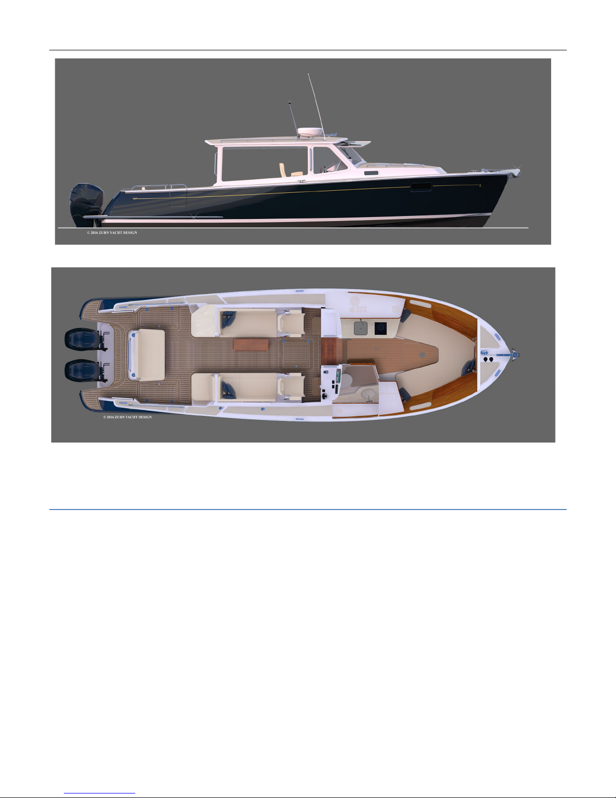
MJM 35z
LOA: Length Over-All
including
engines down & bow roller ............... 37.9
ft.
LOD: Length on deck (LOD ................................................................ 35.7 ft.
Beam (Maximum width on trailer) ......................................................... 11.0 ft.
Maximum Trailer weight (full tanks) ................................................. 15,000 lbs.
Draft with Engines (Up) Down ……………………………………...(1.8 ft.) 2.8 ft.
Displacement (tested weight, no crew) .......................................... 14,250 lbs.
Fuel tank ........................................................................................... 250 gal.
Fresh water tankage (including hot water tank) ...................................... 56 gal.
Holding tank ....................................................................................... 25 gal.
Air height above water to top of radar dome mounted on hard top ......... 9.0 ft.

1 INTRODUCTION
1.1 PURPOSE AND LIMITATIONS
This purpose of this Owners Guide and the equipment suppliers’ manuals in
the accompanying binders is to provide you with an overview of the yacht’s
equipment, operation, systems and maintenance. The people at MJM and
Boston BoatWorks have taken pains to edit this guide for accuracy in good
faith. Most of these topical require further study and learning by the captain of a
vessel who assumes extensive responsibilities for safe operation of the vessel
and for safety of the crew.
This summary guide of yacht equipment and operation will never be complete
or accurate in all respects. And, since we frequently make improvements, we
assume no responsibility for missing information or errors contained herein. This
document doesn’t replace common sense nor qualify the reader in safety
practices, boat handling or navigational skills. Mastering these systems and the
skills of seamanship is each owner’s/captain’s responsibility. If this is your first
yacht, or if you’re changing from a different type of yacht, please get instruction
and experience before assuming command. Your dealer, yacht club, marina or
the US Power Squadron https://www.usps.org are all good resources that can
recommend licensed captains, schools or other instructional entities.
Although this guide and the accompanying binders describe systems on the
boat, they don’t qualify you to work on them. When they need attention, please
use qualified and certified trades personnel. If you question the information or
are unsure about an action, check with the equipment supplier, a qualified
person or us.
The Appendix includes other useful information. And there’s a chapter on the
people who create MJM yachts you can contact if you need help. Study these
resources to understand how to operate your yacht safely.
The operation of a powerboat can be dangerous. Pay careful
attention to safety notices in this guide and in the manuals in the binders.
Keep this guide in a secure place on the boat. If you sell the yacht, please give
this copy to the new owner.
1.2 STANDARD SPECIFICATIONS
You may download the latest version of this guide and the standard
specifications for a MJM35z from http://www.mjmyachts.com/35z to install on
your computer, an iPad or navigational display.
1.3 CONVENTIONS
When we reference a specific device or item of equipment on the boat, it will
be in all caps, such as HOUSE BATTERY.
As we describe each device we often use the following order.
1. BREAKER PANEL settings
2. Function, what it does
3. Directions for use
4. Advice or comments in a sidebar
5. The URL for the manual if available
This guide is published in accordance
with ISO standard 10240:1995E Small
Craft - Owner’s Manual.
Please contact us if you have a question
about the material in this book, if you find
a conflict between this material and the
material in the binders or if you find an
error or important omission on the
following pages please contact
Customer Service at Boston Boat
Works.
…R.I.J.
2 SAFETY and some USCG REQUIREMENTS
2.1 BINDER MANUALS
The equipment suppliers’ manuals in the accompanying binders have many
safety notices that relate to their products, their operation and maintenance and
their use in the boat. Ensure that you understand this essential information
before you operate the boat. Spend time reviewing the safety procedures, how
safety equipment works and where It’s stowed. Instruct guests in safety
procedures.
2.2 STANDARD EQUIPMENT
VHF Radio BREAKER PANEL settings: ELECTRONICS breaker on. The VHF RADIO
may be used for receiving weather broadcasts, communicating with harbors,
locks (ch13), bridges (ch 9), marinas, the U.S. Coast Guard (USCG), rescue
services boats and other boats. The USCG monitors channel 16. If you normally
have your radio tuned to channel 16 you can listen for emergency calls from
nearby boats or be able to make an emergency call quickly. Don’t use Channel
16 for a private conversation.
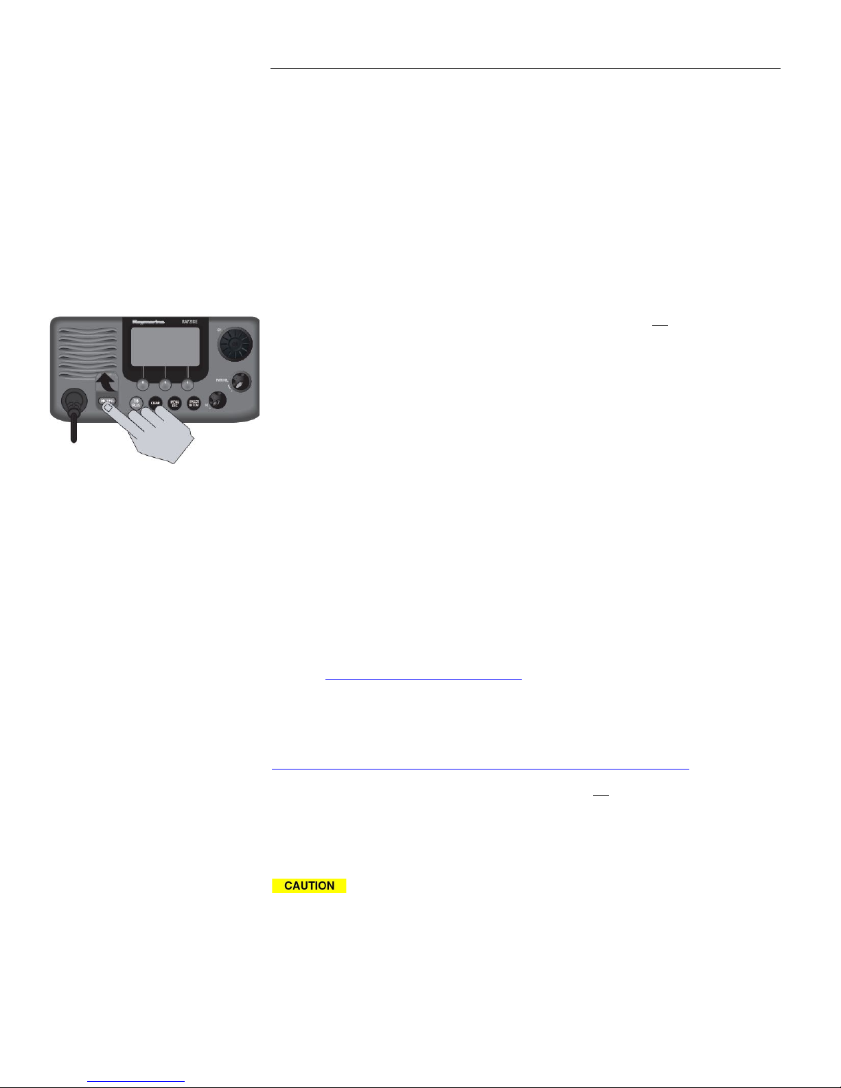
MMSI Number The radio has Digital Selective Calling (DSC). It’s arguably the
most important piece of safety equipment on the boat. There’s a one-button
emergency transmit button that sends a Maritime Mobile Service Identity (MMSI)
number to the USCG. The signal identifies the boat. It’s interfaced with GPS so
your position will be sent with the emergency message. The Automatic
Identification System (AIS) will report your MMSI number to other vessels and
you will see their MMSI number. If you sell your boat, log onto your account to
cancel the MMSI number, so the new owner can register, acquiring a new MMSI.
In addition to the safety function, an MMSI number is like a phone number. You
can make a call to another DSC-equipped vessel if you know its MMSI number.
Only the vessel being called will receive the hail.
BoatUS http://www.boatus.com/MMSI/ is authorized by the Federal
Communications Commission and the USCG to assign MMSI numbers. The
Installation and Operation Instructions for the VHF RADIO included in the binder
explains how to install the MMSI number in your radio. It also explains how to
use the VHF RADIO. It may be downloaded at:
https://raymarine.app.box.com/s/grwg60669c5sozf6iolq/1/2757682985
The Horn BREAKER PANEL settings: HORN breaker on. The USCG requires a
“Sound Producing Device” for signals under many circumstances. The HORN is
operated from a switch on the CONSOLE SWITCH PANEL at the helm. The
adjacent UNDERWAY HORN/ANCHOR switch has programmed signals. (See
page 13.)
Electronics fail. It’s wise to have a portable VHF radio, GPS receiver,
SEARCHLIGHT and HORN that are battery operated and hand held.
Fire Extinguishers See EMERGENCY DIAGRAM page 5 for Fire Extinguisher
locations when the boat is delivered.
Carbon Monoxide Detector See EMERGENCY DIAGRAM page 5.
To send a distress call (without
specifying its nature) press and hold the
red distress key for 3 seconds. See
Ray218E/Ray55E Installation and
Operation Instructions.

Companionway Hatch Board or Closure A companionway board with the label
“DON’T REMOVE WHILE UNDERWAY” is provided to comply with ISO requirements
for cockpit draining and to prevent large waves from crashing down into the
cockpit, running forward and entering the interior of the boat if the
companionway door is not securely closed.
2.3 COMMISSIONING PACKAGE SAFETY ITEMS
The Commissioning Package Option, if purchased with your boat, will have:
• A copy of the U.S. Department of Homeland Security United States Coast
Guard Navigation Rules to be on board. It also may be downloaded at:
http://www.navcen.uscg.gov/pdf/navrules/navrules.pdf
• A First Aid Kit
• Twelve wearable USCG approved personal flotation devices (life-jackets)
and one type IV throwable PFD
• A 12-Gauge Flare Kit
• A Hand-held Bilge Pump
• A Hand-held LED Flashlight
• Paper Charts
2.4 USCG REQUIRED EQUIPMENT
A Boater’s Guide to the Federal Requirements for Recreational Boats, published
by the USCG, lists required safety items. The Guide may be downloaded at:
http://www.uscgboating.org/images/420.PDF. Check state regulations where
you cruise for other requirements.
2.5 ADDITIONAL SAFETY EQUIPMENT
There are many other items of safety equipment to consider such as:
EPIRB (Emergency Position Indicating Radio Beacon) alerts search and rescue
services by transmitting a coded message and is detectable by satellite
anywhere in the world. Although the USCG doesn’t require them, EPIRBs are
essential offshore and desirable anywhere.
Inflatable Life Raft isn’t required but prudent. Rafts come in compact sizes that
can be stored in a cockpit locker. A dinghy isn’t a substitute for a life raft.
Heaving Line is handy to have for emergency or to simply trail behind the boat (if
the engines are off) attached to one of the stern cleats when people are
swimming. Polypropylene is good because it floats.
A Storm Anchor is useful as a back up and for situations when two anchors are
prudent or necessary.
2.6 SOME ADDITIONAL USCG REQUIREMENTS
In addition to the above safety equipment, the USCG requires:
Ships Registration and Documentation Carry the Vessel Registration, either the
state-issued Certificate of Number or Vessel Documentation if federally
documented with the USCG. It’s wise to have your insurance as well.
Pollution Regulation Plaques You are required to post three visible placards in
the boat that stipulate that waste must be managed; that oil discharge is
prohibited and deposit of any refuse matter of any kind into the waters of the US
is prohibited. West Marine has such plastic placards with adhesive backs that
are available at little or no cost.
Better to just secure the companionway
slider and lid. It’s quieter, prevents
someone from being pitched below and
provides a Chart Kit navigation surface.
---R.I.J.

2.7 FUEL SHUT-OFF VALVES
The first thing to do if there is a fuel fire or leak is stop engines, turn off ignition
and engine battery switches and close fuel shut-off valves by turning them
perpendicular to the hose. They are located in the cockpit locker, looking
forward over the generator at the back end of the fuel tank. If there is fuel in the
bilges, close valves, find the source of the leak and then clean bilges.
2.8 FIRE SUPPRESSION
An automatic, heat-activated, fire suppression system is installed in the
generator compartment. It can be activated manually at the helm station. To
prevent the engines from evacuating the fire suppression agent when it
discharges, the system will shut off blowers and generator. Refer to the manual
for maintenance instruction. (
Hand-held fire extinguishers (see Emergency Diagram page 5 for locations) are
rated to fight type A, B & C fires. To extinguish a fire, first cut the source of fuel
to the fire. In a fuel fire, turn off the fuel tank valves. In an electrical fire, turn off
the BATTERY switches.
Fire safety begins with prevention. Reduce fire risk with these guidelines:
• Don’t allow debris or oily rags to collect anywhere.
• Check bilges for oil or fuel regularly.
• Shut down unnecessary circuits when leaving the boat.
• Don’t leave heat-producing appliances or equipment unattended.
• Inspect fire suppression equipment regularly and learn how to use it.
Exhaust gas contains carbon monoxide. It’s colorless, odorless and
lethal. Avoid inhaling. Inspect the exhaust system regularly. Idling engines at a
mooring or at a dock isn’t good for the engine and may allow gasses to
accumulate in the cockpit or cabin.
Don’t work on any mechanical or electrical equipment unless you’re
qualified. Electrical current and moving parts are dangerous and can be lethal.
2.9 NOTICES
Denotes a reminder of safety practices or directs attention to unsafe
practices which could result in personal injury or damage to the craft or
components.
Denotes a hazard that exists which can result in injury or death if
proper precautions aren’t taken.
Denotes an existing extreme intrinsic hazard that would result in high
probability of death or irreparable injury if proper precautions aren’t taken.
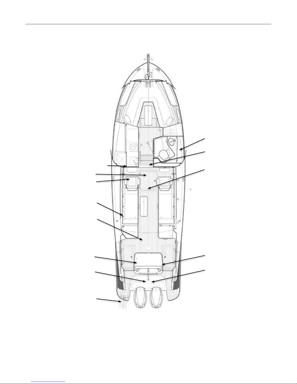
2.10 EMERGENCY AND THRU HULL DIAGRAM
Seakeeper 3
Manual Bilge Pump
Shore Power Breakers
Fuel Shut-off Valves on
Tank
Seakeeper & AC Raw Water
Strainer & Thru Hull
Generator Room SeaFire
Swim Ladder Under
First Aid Kit
Waste Discharge Thru Hull
Electric Bilge Pump 1
Generator Raw Water Groco
Strainer & Thru Hull
Electric Bilge Pump 2
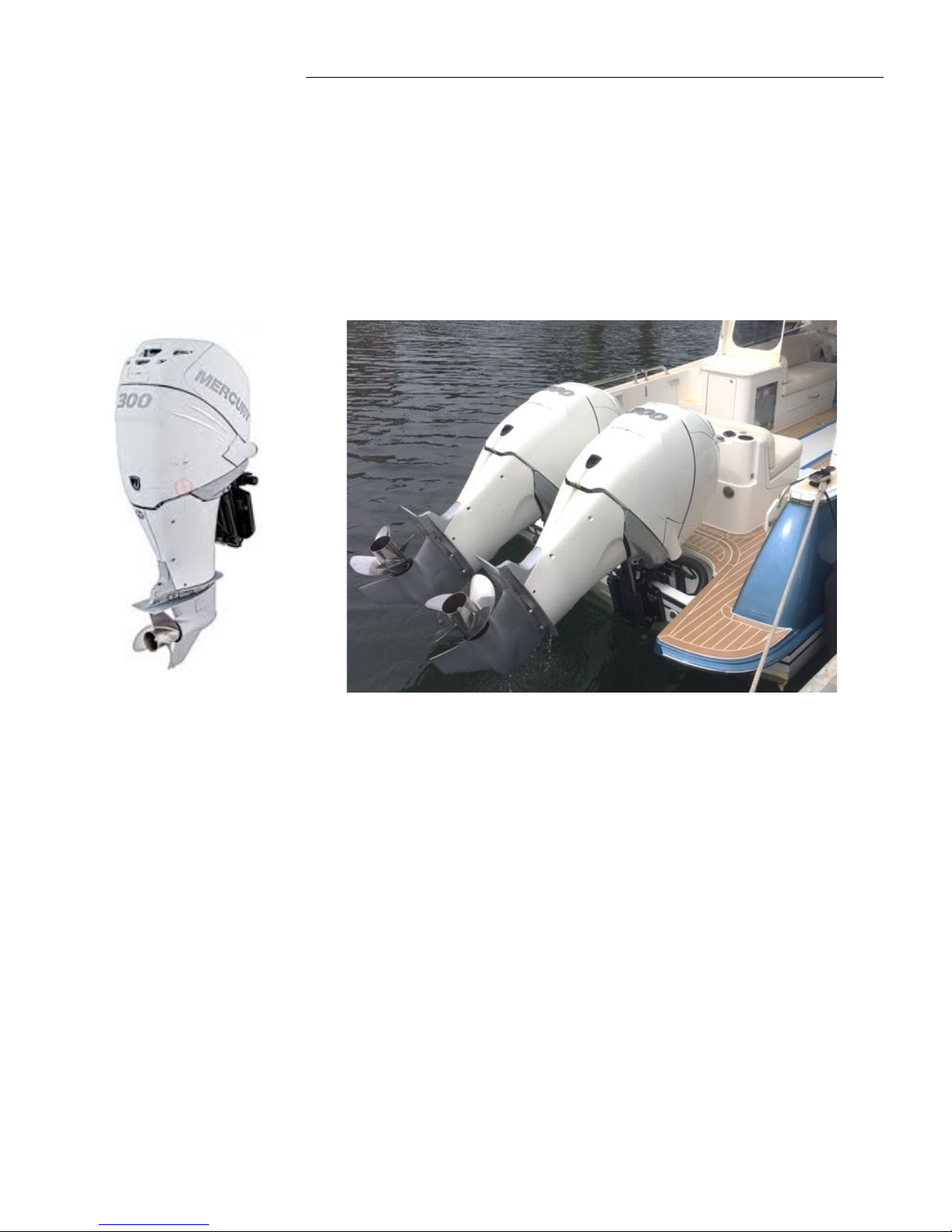
3 PROPULSION
3.1 ENGINES
The MJM 35z is propelled by twin Mercury Verado 300 or 350 HP 4-stroke, 6cylinder in-line outboard engines with HD heavy duty drives having either 3 blade
Enertia-ECO 3-Blade or 4-blade Evolution-4 stainless steel propellers. When
raised, engines are out of the water.
3.2 ENGINE CHECKS
See “Mercury Operation & Maintenance Manual (MOMM”) provided with your
MJM. Before long trips, checki hydraulic steering fluid level under the rear
cockpit seat and engine oil level by removing the top cowl.
Top Cowl Removal to access most maintenance points. To tilt the engine
closer, making this easier, use the small black AUXILIARY TILT SWITCH on the
port side of the engine just below the top cowl.
Pull up on the top cowl latch on the back of the engine.
Pull the top cowl forward and lift off.
Remove dipstick on port side of engine to check oil, then securely reinserti.
Putting the top cowl back on is a bit tricky. Position the top cowl loosely in
place over the engine, being sure it fits on top of the rubber seal all the way
around. (MOMM says front first)..
Push down on the cowl, MOMM says back half first, then front half until it
clicks into place. Make sure it’s secure by pulling up on the back of the cowl.
Don’t want this flying off underway!
Carbon Streaks rub off with a swipe of the hand when hosing down boat.
Water Separating Fuel Filters should be replaced every 100 hours or annually.
They are located on bulkheads outboard of the generator and aft of the fuel shut-
off valves on top of the fuel tank.
The wire out of the bottom of the filter bowl is the sensor to alert that water is in
the filter. This is not usually of an urgent nature, but rather a “change at next
opportunity” event.
In-Line Fuel Filter under the engine cowl should also be replaced every 100
hours or annually. This pencil like deviice primarily capturres fabrication debris
picked up by the fuel in the tanks or hoses. Rarely does fuel clog it. (See
MOMM pg 76)
Check Fuel Level The primary cause of engine failure is running out of fuel.
There’s a fuel level sensor in the 250 gallon tank and read out on VESSEL VIEW.
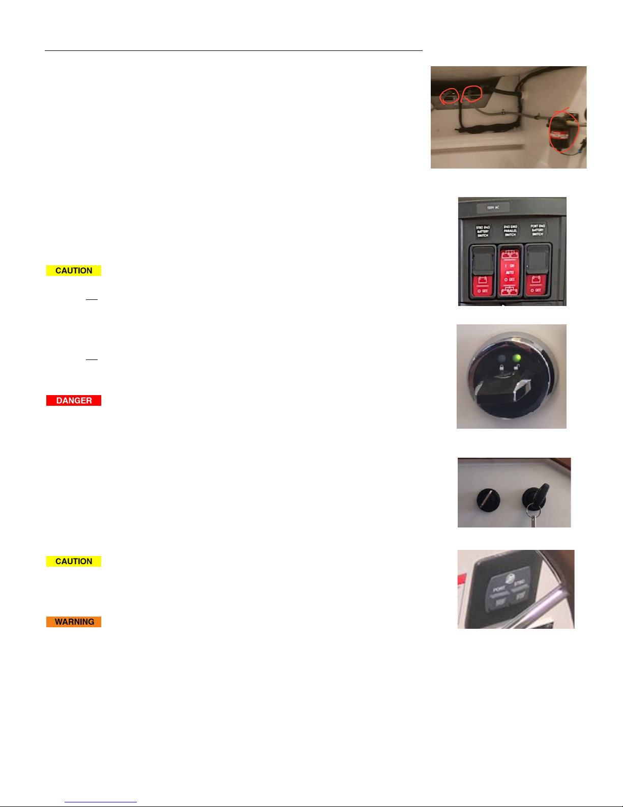
3.3 5 STEPS TO START
Ensure
there are no l
ines and hoses in the water near the props.
1. Turn on the PORT & STBD ENGINE BATTERY switches switch at the upper
right of the lower (120v) breaker panel inside the companionway.
2. Insert the TPS fob into it’s indeptendent slot above the electrical panels..
3. Turn on both engine ignition keys at the top of the bulkhead inside
companionway where they can’t be accidentally bumped into when entering or
exiting the interior.
Don’t start the engine if people are in the water nearby.
4. Lower engines using the rocker switch on the port control handle. Ensure
the ENGINE/SHIFT CONTROL LEVERS are in neutral. The engines won’t start if
either lever is in gear.
5.
START ENGINES,
push and immediately release the engine start button for
each engine to starboard of the wheel. Do not hold them in as process is
automatic until engine starts. If you don’t hear the engines (these are quiet
boats) look at the VESSEL VIEW DISPLAY panel to see they read 500-600 rpm
idle. Also check to see if the Joystick base rim lights up GREEN indicating that it
is active. See JOYSTICK PILOTING
The boat may move abruptly when the gear is engaged. Ensure the
boat is clear of all obstacles forward and aft. Cautiously shift to the IDLE
FORWARD position then quickly back to NEUTRAL position. Observe whether the
boat moves as you expect.
If a warning light or buzzer activates, stop the engine immediately.
Determine the cause and repair the problem before continuing to operate.
3.4 STOPPING THE ENGINES
Put ENGINE/SHIFT CONTROL LEVERS in neutral. Push the lower STOP buttons on
START/STOP Panel. The green base of the Joystick goes out and RPMs go to
“0”. Once the engines have been raised, Reverse the Start process by turning
of Ignition Keys, pulling out the TPS fob (and hiding it) then truning off the two
ENGIINE BATTERY SWITCHES. i
Mercury FUEL FILTERS & Fuel Shut Offs
Engine Battery Switches
TPS (Theft Prevention) fob.
Engine Ignition Keys.
Engine START/STOP Buttons.

It is unnecessary to remove the ignition keys, since they are below and the TPS
fob is hidden ENGINE BATTERY SWITCHES are off and the cabin is locked.
Engine work should not be done with the engine running unless
specified by the manufacturer for a specific reason and done by a qualified
marine mechanic. Stop engines before opening engine hatch.
3.5 NEW ENGINE BREAK-IN
When running the engine for the first time, frequently check oil pressure, coolant
temperature (normal is 145o), exhaust color, engine vibration, sounds and the
operation of indicators and gauges. Don’t run the engine at a constant RPM for
long periods of time or apply full throttle for more than about 30 seconds.
Lubrication During the first 10 hours of operation, high oil consumption is
typical. Change oil between 50 and 100 hours. Consult the MOMM for the
proper oils for the climate where the boat will be operating.
3.6 OPERATING PARAMETERS
Pay attention to the engine data on the VESSEL VIEW or displayed on the
Raymarine gS165 data bar. A significant change in oil pressure, coolant
temperature or pressure, or voltage drop should be quickly investigated before
the engine is damaged. Data should read approximately:
• Oil Pressure: 50 psi at 3000 RPM or more.
• Coolant Temperature: 145o F to 165 o F
• Coolnant Pressure over 3000 RPM: 15-25 psi.
• Charging: 13-14 Volts underway
While Mercury has run their engines for 300 hours straight at max RPM without
damage, a good fast cruising speed is 35-37 knots. or about about 90% of max
RPM at about 5200 RPM. Listen and feel for sweet spots. If you hear abnormal
sounds, stop the engine and inspect.
3.7 LEAVING THE BOAT
With SHOREPOWER connected - Leave 12v HOUSE BATTERY switch on, as well as
REFRIGERATOR breaker. And, on AC Panel: leave BATTERY CHRGR, ICEMAKER and
AIR CONDITIONER breakers on.
Check that BILGE PUMP switches are set to AUTO
Turn off INVERTER breaker on AC Panel and on PHOENIX CONTROL
If moored or with no shore power, If gone for more than a week, it’s best to
turn everything off, including the MAIN INVERTER UNIT itself under the starboard
pilothouse settee, to avoid the risk of having dead batteries when you return.
Or, take advantage of the optional156W SOLBIIEN SOLAR PANEL. With
INVERTER on It is designed to keep REFRIGERATOR and ICEMAKER going
with a trickle charge to the HOUSE BATTERIES if not connected to Shore
Power..
Flushing the Engines If you plan to let the boat sit for more than a few days,
MOMM advises to flush the engines by hooking up a dock hose to the flush
connectior on the port side of the engines next to the auxiliary lift button and
lettig it run for about 15 minutes. See MOMM page 70. A “Y” hose connector
would be helpful here to have both engines flushing at once.
A reboot can solve mysterious issues.
Electronic engine controls are
computers. Mysterious problems
emerge and may be caused by unusual
switching sequence. They can often be
fixed with a reboot. Stop the engines.
Turn everything off—shut down the
entire boat. Wait at least 10 seconds.
(My printer and router call for 25
seconds.) Then turn HOUSE BATTERY
and ENGINE BATTERY switches on (but
not the ENGINE EMERGENCY,
PARALLEL switch). Go on deck. Turn
Ignition switches on at the helm. Wait
until the engine control display shows
data and has gone through its initial
warm up. Then start the engines and
check the Joystick Control functions (IPS
& DPS).
…R.I.J
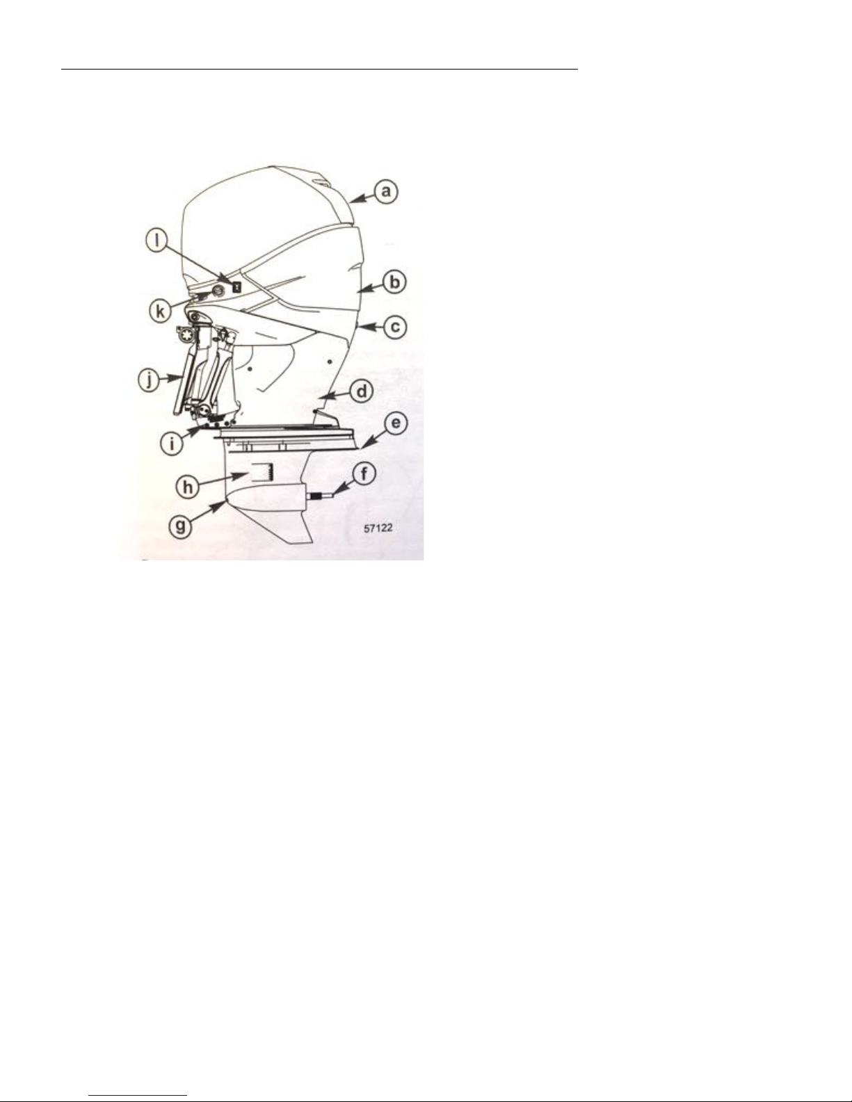
3.8 MERCURY VERADO 300 & 350 HP ENGINES
a. Top Cowl
b. Rear Cowl
c. Idle Relief Exhaust
d. Lower Cowl Chaps
e. Anti-Ventilation Plate
f. Propeller Shaft
g. Low Water Intake Holes
h. Water Intake Holes
i. Trim Guide Plates
j. Pedestal
k. Engine Flush
l. Auxiliary Lift Switch
4 INSTRUMENTS AND CONTROLS
The following material includes selected summaries of the Volvo Penta
Operator’s Manual (VPOM) included in the binders. Please read the entire
manual for safety instructions. There are frequent page references to the VPOM
in the following paragraphs.
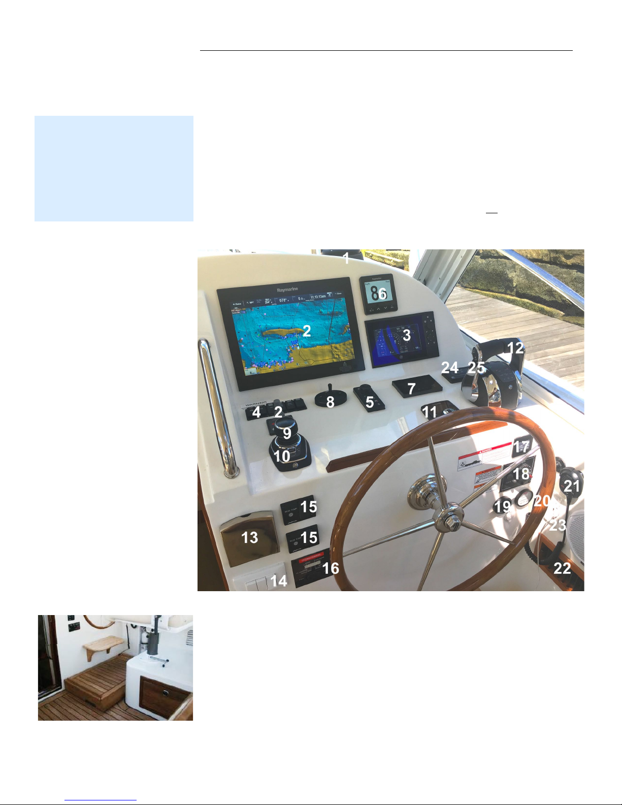
4.1 HELM STATION
Most of the boat’s controls and instruments are at the helm station. Below is the
layout on ZINNIA #1. The respective circuit breakers must be on for the
equipment to operate.
Esthec Riser (Option) This 4” high removable riser improves visibility for
someone shorter than 5’5”. It locks into place with a barrel bolt and can be
stored in one of the settee lockers.
35z power steering rotates outboards
through a 20° arc. The steering is more
positive and immediate than deflecting
prop wash off a rudder from a propeller
on a straight shaft and far more positive
than directing a jet of water at water
passing the hull..
…R.I.J.
1 Ritchie Compass
2 Raymarine gS165 MFD
3 Mercury VesselView
4 Console Switch Panel
5 Raymarine MFD Control Pad
6 Raymarine Multi-display with Depth
7 Seakeeper Control Panel
8 Searchlight Control
9 Mercury Joystick Piloting
10 Autopilot Button
11 ZipWake Auto Trim
12 Engine/Shift Control Levers
13 Flip Down Drink Holder
14 Pilothouse Light Switches
15 Bilge Pump Controls (2)
16 Generator Start/Stop
17 Engine Start/Stop
18 Windlass Up/Down
19 High Water Alarm
20 Fire Suppression Alarm
21 VHF RAM
22 Air Conditioning Register
23 GFI/USB for Cell Phone
24 Mercury Active Trim
25 Engine Up/Down Rocker Switch.
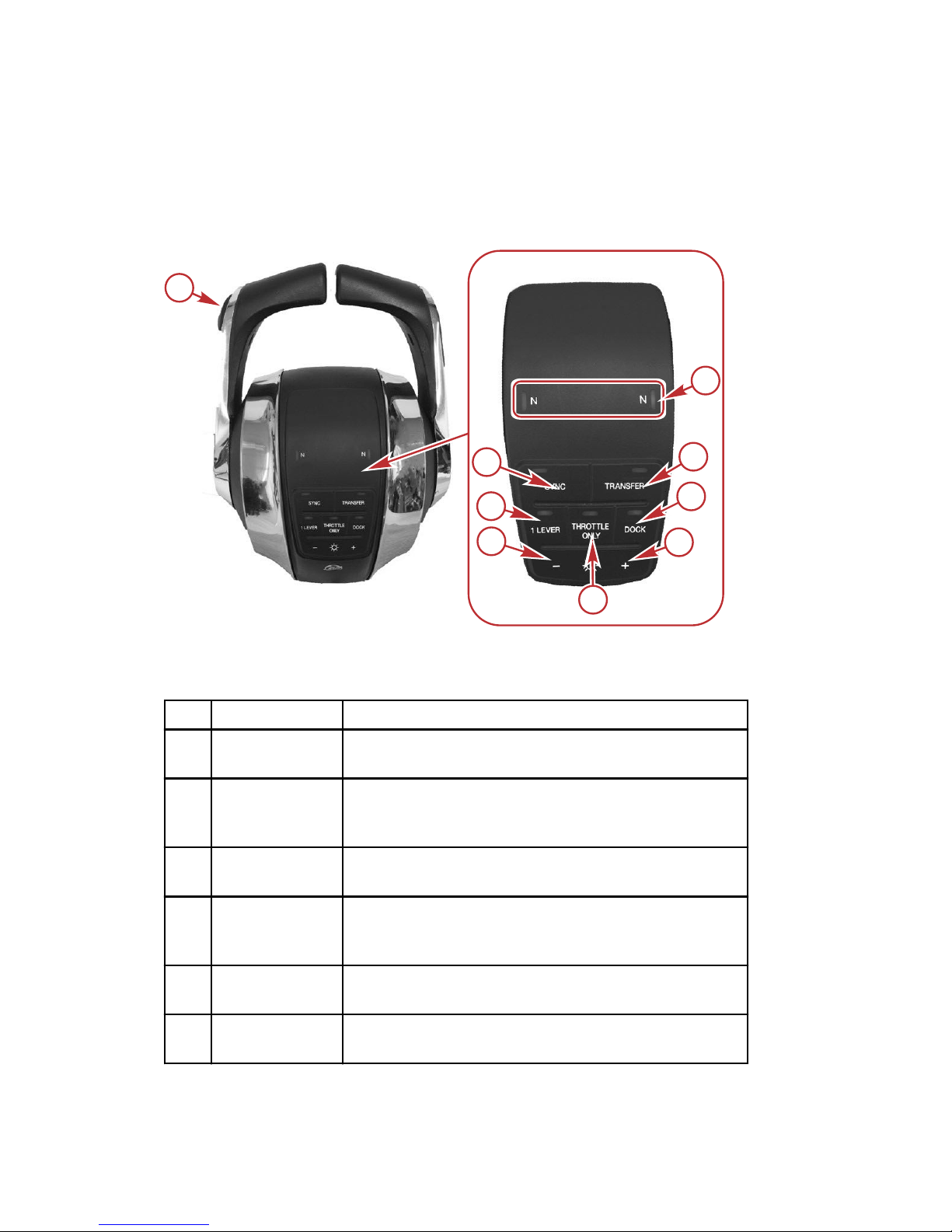
SPECIAL DIGITAL THROTTLE AND SHIFT (DTS) FEATURES
The DTS system features several alternate operational modes for the electronic
remote control (ERC) levers. Any of the listed features can operate
simultaneously.
b
c
d
e
f
g
h
i
55232
a
Dual engine ERC
Item Control Function
a
Trim control
(handle)
Raises and lowers the engines for best efficiency, or
for conditions such as shallow water, trailering, etc.
b
NEUTRAL
lights
Illuminate when the drive is in the neutral gear
position. The lights flash when the engine is in
throttle only mode.
c TRANSFER
Allows boat control to be transferred to a different
helm. Refer to Helm Transfer.
d DOCK
Control lever operation reduces throttle capacity to
approximately 50% of normal control lever throttle
demand.
e +
Increases brightness settings for CAN pad,
VesselView and SmartCraft gauges.
f
THROTTLE
ONLY
Allows the boat operator to increase engine RPM for
warm‑up without shifting the transmission into gear.
FEATURES AND CONTROLS
56 eng
Item Control Function
g –
Decreases brightness settings for CAN pad,
VesselView and SmartCraft gauges.
h 1 LEVER
Enables the throttle and shift functions of both
engines to be controlled by the port lever.
i SYNC
Turns off or on the auto‑synchronization feature.
Refer to Sync.
NOTE: Not all functions may be active.
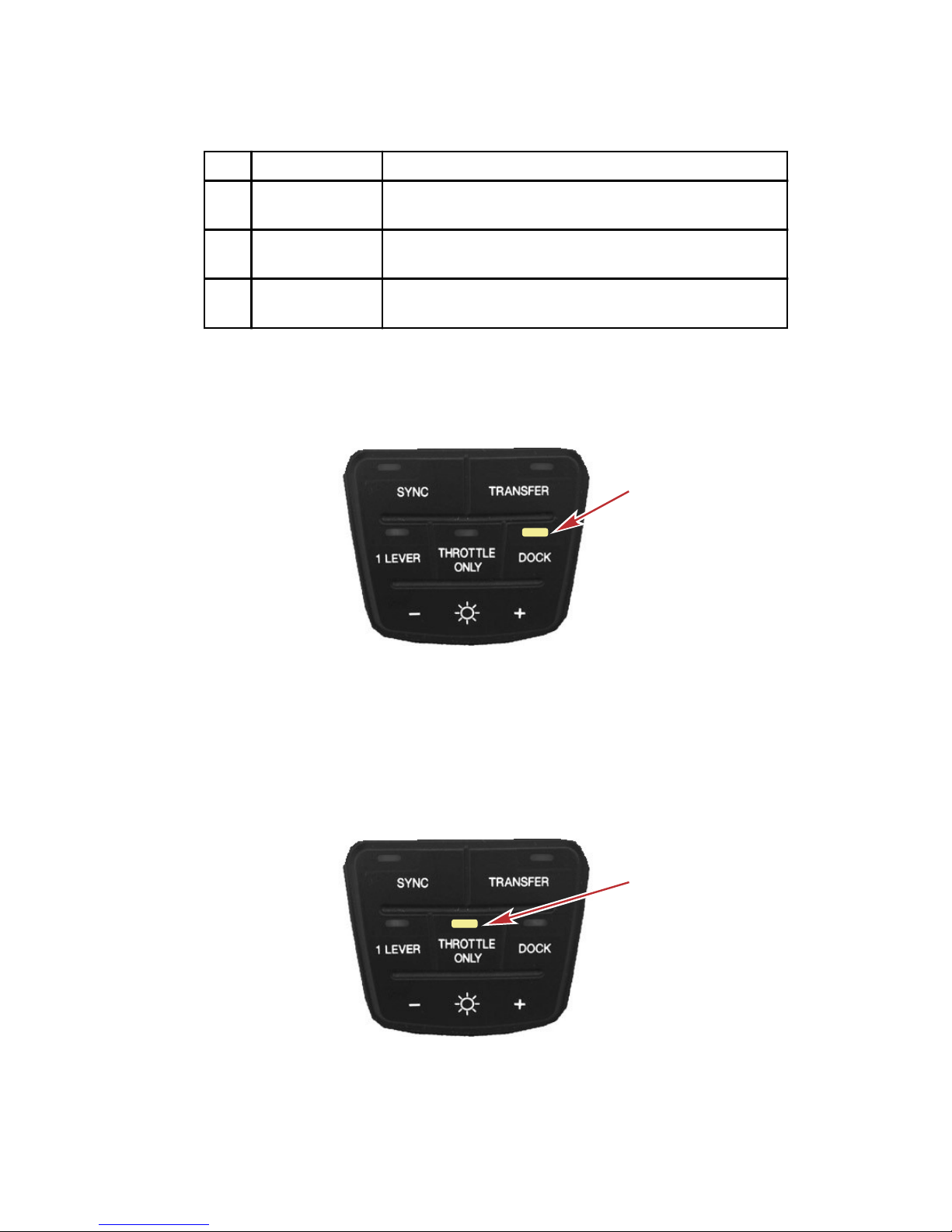
Dock
Dock mode reduces throttle capacity to approximately 50% of normal throttle
demand, allowing finer control of engine power in close quarter situations.
51854
DOCK button
Throttle Only
NOTE: Throttle only mode should be used if the captain is not in command at
the helm. Placing the ERC in throttle only mode will avoid unintended gear
engagement. The engines will turn using the steering wheel and the RPM of
the engines can be increased while in the throttle only mode, but the gear
position will remain in neutral.
51855
THROTTLE ONLY button
FEATURES AND CONTROLS
eng 57
To engage throttle only mode:
1. Place both ERC levers in neutral.
2. Press the THROTTLE ONLY button. The button light will turn on and the
neutral lights will blink.
3. Place either ERC lever into gear. The warning horn will beep each time
the levers are moved in and out of gear while in throttle only, but will
remain in neutral.
4. The RPM of the engines can be increased.
NOTE: Pressing the THROTTLE ONLY button while the ERC levers are not in
the neutral position, turns the button light off and remains in throttle only mode.
You must place the ERC levers into the neutral position to disengage throttle
only mode.
To disengage throttle only mode:
1. Place both ERC levers into neutral. Throttle only will not disengage unless
the ERC levers are in neutral.
2. Press the THROTTLE ONLY button. The button light will turn off.
3. The neutral lights stop flashing and remain illuminated.
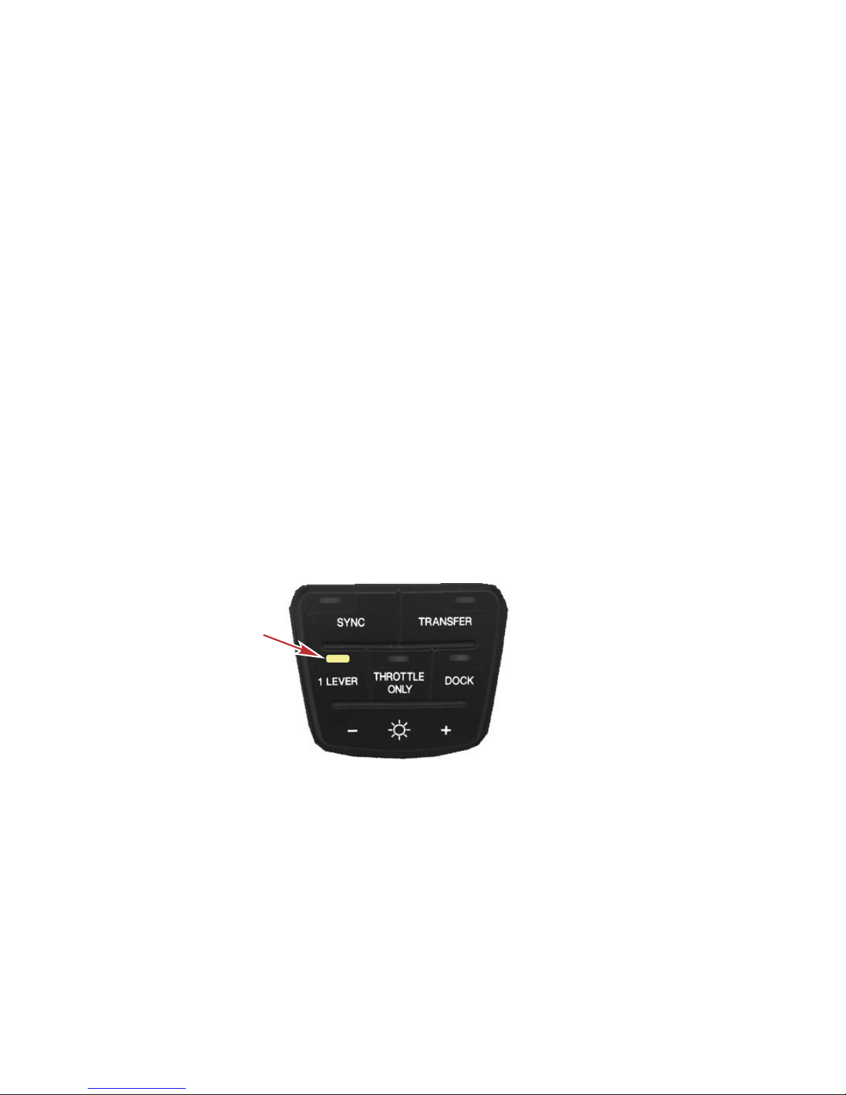
1 Lever
This feature commands both engines with a single lever on a dual engine
application. This feature simplifies engine management during rough sea
conditions by allowing you to use a single lever to command both engines
simultaneously. It is not the same as the system feature called Sync.
51856
1 LEVER button
To engage 1 Lever mode:
1. Place both ERC levers in neutral.
2. Press the 1 LEVER button. The button light will turn on.
3. Place the starboard ERC lever into gear.
4. When the handle is moved, the engines RPM and gear position is
synchronized.
To disengage 1 Lever mode:
1. Place both ERC levers in neutral.
FEATURES AND CONTROLS
58 eng
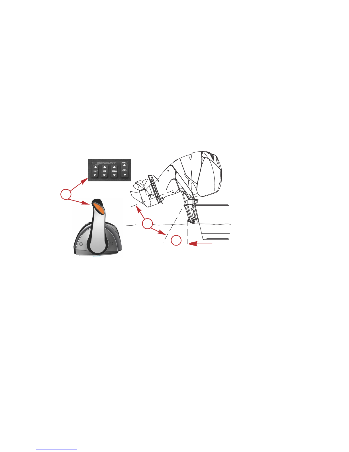
Power Trim and Tilt
The outboard has a trim/tilt control called power trim. This enables the operator
to easily adjust the position of the outboard by pressing the trim switch. Moving
the outboard in closer to the boat transom is called trimming in or trimming
down. Moving the outboard further away from the boat transom is called
trimming out or trimming up. The term trim generally refers to the adjustment of
the outboard within the first 20° range of travel. This is the range used while
operating the boat on plane. The term tilt is generally used when referring to
adjusting the outboard further up out of the water. With the engine not running
and the key switch in the ON position, the outboard can be tilted out of the
water. At speeds below 4300 RPM, the outboard can be tilted up past the
normal trim range.
a - Trim switch
b - Tilt range of travel
c - Trim range of travel
POWER TRIM OPERATION
With most boats, operating around the middle of the trim range will give
satisfactory results. However, to take full advantage of the trimming capability
there may be times when you choose to trim the outboard all the way in or out.
Along with an improvement in some performance aspects comes a greater
responsibility for the operator, this being an awareness of some potential
control hazards.
Consider the following lists carefully:
1. Trimming in or down can:
• Lower the bow.
• Result in quicker planing off, especially with a heavy load or a stern
heavy boat.
a
b
c
57105
FEATURES AND CONTROLS
70 eng
4.2 MERCURY FEATURES AND CONTROLS (PAGES 56 -77)
4.3 JOYSTICK PILOTING
The Mercury Joystick Piloting functions very much like the
Volvo Penta IPS, except it’s more automatic.
MOVE Engine Controls to Nuetral. The ring at the base of
the JOYSTICK lights up Green to show that it’s active.
TWIST Joystick to turn the boat or LEAN Joystick in
direction desired or do both at same time While PUSHING
Joystick forward or aft… without going back to center.
PUSH ADJUST “+” for 100% torque (shows 2 lights).
PUSH “-“ for 50% torque (1 light). “+” is recommended.
ENGAGE Engine Controls to deactivate.
4.3.1 AUTOPILOT Press boat outline button (Lower Left of Joystick) to
engage Autopilot.
TAP Joystick port or starboard to alter course by 1 degree
increments. Beep confirms.
TWIST and RELEASE to alter AP Course in 10 degree increments.
In an emergency, you can forcibly TURN the wheel to disengage
the autopilot
4.3.2 WAYPOINT TRACK Press “Tri-circle” diagram on
starboard side of joystick to set course to WP-1 of course
plotted on Raymarine display. Upon arrival at WP-1, there
will be an audible beep. Push “Tri-circle” button again to
set course to WP-2, etc.
4.3.3 SKYHOOK PUSH “SKYHOOK” button to hold heading
and GPS position. GREEN necklace turns BLUE to indicate
it is active. Seakeeper gyro helps greatly here, too, so
waves don’t readily throw the bow around.
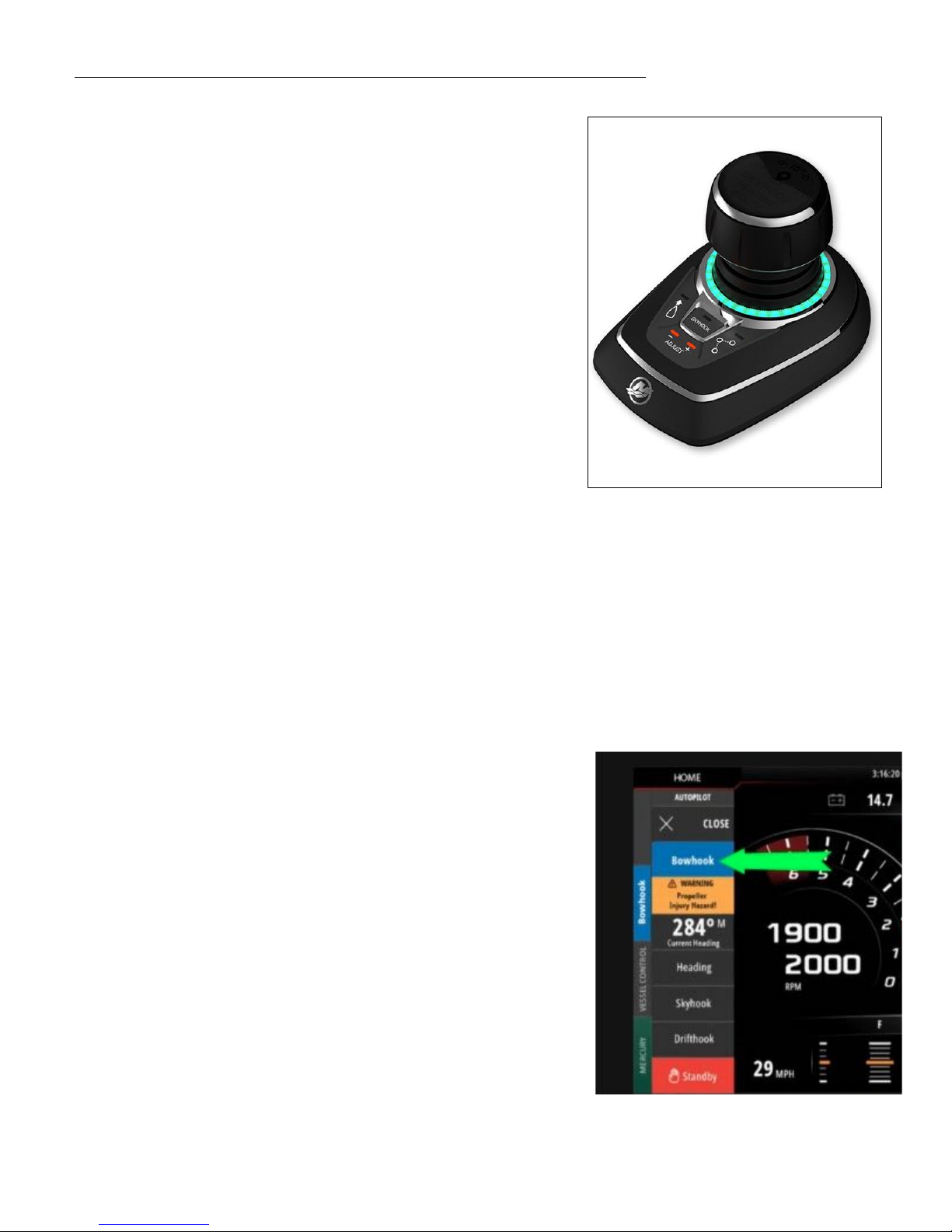
4.3.4 BOWHOOK With SKYHOOK activated, PUSH “Bowhook”
on Vessel View screen to hold GPS position, but unlock
compass heading allowing boat to point into direction of
wind/current so engines don’t have to work so hard to keep
boat in position. See illustration at right.
 Loading...