


Semiautomatic Pallet
Wrapping ROBOT
https://goo.gl/Xm1XrR
BeeWrap
Operation and maintenance
manual
Translation of the “ORIGINAL
INSTRUCTIONS”
Code SBC0032307
ed. 09-2017 - rev. 4

No part of this publication may be reproduced without the written consent of the Manufacturer. Pursuing a policy of continuous improvement, the Manufacturer reserves the right to change this
document without notice, provided that such changes do not create risks to safety.

Summary
Safety information
Purpose of the manual ..................................................................................................................... 3
Glossary of the terms ....................................................................................................................... 4
Attached documentation .................................................................................................................. 5
General safety warnings .................................................................................................................. 5
Safety Warnings for Handling and Installation ................................................................................. 6
Safety Warnings for Operation and Use........................................................................................... 7
Safety Manager Obligations ......................................................................................................... 7
Safety Warnings on Misuse.............................................................................................................. 8
Safety Warnings on Residual Risks ................................................................................................. 8
Safety Warnings for Maintenance and Adjustments......................................................................... 9
Safety warnings for the electrical equipment ................................................................................. 10
Safety warnings for the environmental impact ............................................................................... 10
Safety and information symbols ......................................................................................................11
Technical Specications
general description of the machine ................................................................................................ 13
Description of the main components .............................................................................................. 14
Manufacturer and machine identication ....................................................................................... 16
Cycle .............................................................................................................................................. 17
Types of wrapping .......................................................................................................................... 18
Residual risks ................................................................................................................................. 19
Incorrect uses that are reasonably expected ................................................................................. 20
Optional Accessories ...................................................................................................................... 21
Description of the safety devices ................................................................................................... 22
Specications ................................................................................................................................. 23
Description of outer areas .............................................................................................................. 25
Position of information and safety plates ....................................................................................... 26
IDM 510-032-5_Sommario
Use and functioning
Recommendations on Operation and Use ..................................................................................... 27
Control description ......................................................................................................................... 28
Emergency stop and new start-up ................................................................................................. 32
Stop with activation of the emergency button ............................................................................. 32
Stop with activation of the emergency bumper ........................................................................... 32
(Single or double) automatic wrapping ........................................................................................... 33
Normal stop ................................................................................................................................ 34
(Single or double) automatic wrapping with sheet feeder .............................................................. 35
Normal stop ................................................................................................................................ 37
Setup of parameter values ............................................................................................................. 38
Recipe management ...................................................................................................................... 39
Modifying a recipe ....................................................................................................................... 39
Loading a recipe ......................................................................................................................... 40
Recipe lock/unlock mode ............................................................................................................... 41
Recipe function “P0” ................................................................................................................... 41
Disassembly and reassembly of battery panel ............................................................................... 42
Assembly of battery panel .......................................................................................................... 42
English languageOperation and maintenance manual
1

Maintenance
Recommendations for maintenance interventions ......................................................................... 43
Scheduled maintenance intervals .................................................................................................. 44
Daily check of the safety bumper ................................................................................................... 45
Monthly check of the safety bumper .............................................................................................. 46
Yearly check of the safety bumper ................................................................................................. 48
Recommendations for accumulator batteries ................................................................................. 49
Maintenance of accumulator batteries (GEL) ................................................................................. 50
Maintenance of accumulator batteries (ACID) ............................................................................... 50
Charge of accumulator batteries .................................................................................................... 51
Problems, causes, remedies .......................................................................................................... 53
Alarm message table ..................................................................................................................... 54
How to adjust the feeler ................................................................................................................. 56
Sensitivity adjustment for the product to be wrapped detection photocell ..................................... 57
Replacing the lifting belt of the carriage ......................................................................................... 58
Battery replacement ....................................................................................................................... 60
Machine Disposal and Scrapping ................................................................................................... 61
Reel holding carriages
Reel holding carriage (M) ............................................................................................................... 62
Main components ....................................................................................................................... 62
Film Coil Feeding ........................................................................................................................ 63
Tension adjustment of lm .......................................................................................................... 63
Cleaning and replacement of brake disc .................................................................................... 64
Replacing the outer surface of roller ........................................................................................... 65
Reel holding carriage (FM) ............................................................................................................. 66
Main components ....................................................................................................................... 66
Film Coil Feeding ........................................................................................................................ 67
Tension adjustment of lm .......................................................................................................... 67
Cleaning and replacement of brake disc .................................................................................... 68
Adjustment of brake .................................................................................................................... 69
Replacing the outer surface of roller ........................................................................................... 70
Reel holding carriage (LP) ............................................................................................................. 71
Main components ....................................................................................................................... 71
Film Coil Feeding ........................................................................................................................ 72
Tension adjustment of lm .......................................................................................................... 72
Replacement of pre-stretch kit .................................................................................................... 73
Net-type reel holder carriage .......................................................................................................... 75
Main components ....................................................................................................................... 75
Supplying the reel with net .......................................................................................................... 76
Adjustment of net tension ........................................................................................................... 76
Cleaning and replacement of brake disc .................................................................................... 77
Replacement of the net tensioning roller .................................................................................... 78
Analytical index ............................................................................................................................ 79
2
English language Operation and maintenance manual
IDM 510-032-5_Sommario

Purpose of the manual
– The purpose of the manual is to inform and train operators so that they can interact
with the machine in SAFE CONDITIONS.
– Its aim is also to prevent risks, to reduce the social costs resulting from accidents and
damage to the health of people, property and to the environment.
– In some cases, accidents may be due to the Operator using the machine care-
lessly.
– Caution is always necessary. Safety is also the responsibility of all the persons
interacting with the machine throughout its operating life.
– Remember that it is too late to think about safety issues when the accident has
already occurred.
– Reading the Operating Instructions is fundamental in order to minimize the risks
and avoid accidents.
– The content of this manual was originally edited by the Manufacturer in the mother
tongue (ITALIAN), in compliance with the professional writing standards and the regulations in force.
Safety information
– Any translation of the manuals shall be carried out directly and without alterations from
the texts of the ORIGINAL INSTRUCTIONS.
– This applies also to the translations carried out by the agent or by the person who is in
charge of delivering the equipment in the specic linguistic area.
– The Manufacturer reserves the right to make any changes to the content of the manu-
als without prior notice, provided that such changes do not alter the safety level.
– All information supplied by the recipients represents an important contribution to the
improvement of the after-sales service that the manufacturer will offer to his/her customers.
– All supplied information is organised into an index and a table of contents, so as to
easily track specic topics of interest.
– The SAFETY WARNINGS and the INSTALLATION MANUAL are supplied as hard-
copy publications.
– The USE AND MAINTENANCE MANUAL, operation diagrams and all other post-
sale documents can be downloaded from the INTERNET.
– Keep the manual and the attached documents in a place known and easily traceable,
so that you may refer to them whenever necessary.
IDM 510-004-3
English languageOperation and maintenance manual
3

Glossary of the terms
The glossary includes some terms used when processing information, with their
denition, in order to facilitate understanding.
– Training: A process aiming at transferring the knowledge, skills and behaviours re-
quired to work in an autonomous, correct and hazard-free manner.
– Assistant: person chosen, trained and coordinated in an appropriate manner to mini-
mize the risks in carrying out their tasks.
– Emergency stop: voluntary activation of the special control that stops the dangerous
elements of the work unit in the case of imminent risk.
– Stop in alarm conditions: this state causes the components to stop and is activated
when the control system detects a problem in the machine operation.
– General shut down: In addition to the normal stop this state also causes the interrup-
tion of all the power sources (electrical, pneumatic, etc.).
– Operating Stop: state that does not cut off power supply to the actuators, but ensures
control system monitoring in safe conditions.
– Size change: a set of interventions to be carried out before beginning to work with
specications different with respect to the ones previously in use.
Safety information
– Test-run: a series of operations required to ensure compliance to the design speci-
cations, and to commission the machine under safety conditions.
– Installer: a technician chosen and authorized by the manufacturer or his authorized
representative, among those who full the requirements for installation and testing of
the machine or plant in question.
– Maintenance Operator: a technician chosen and authorized, among those who full
the requirements, to carry out routine and extraordinary maintenance operations on
the machine. Therefore, the maintenance operator shall possess precise knowledge
and skills, with particular skills in the relevant eld.
– Routine Maintenance: all the operations necessary to maintain the functionality and
efciency of the machine. Normally, these operations are scheduled by the manufacturer, who denes the necessary skills and methods of action.
– Operator: a person chosen and authorized, among those who full the requirements,
having the knowledge and skills necessary to operate the machine and carry out routine maintenance interventions.
– Person in charge of the installation: a technical expert who must carry out the instal-
lation in compliance with the laws applicable to the workplace and, at the end, assess
its compliance.
– Residual risks: all the risks remain even if all the safety solutions have been adopted
and integrated when the machine has been designed.
– Expert Technician: A person authorised by the Manufacturer and/or his representa-
tive to carry out services that require specic technical skills and abilities.
– Forwarder and Handler: Authorized persons with recognized expertise in the use of
means of transport and lifting devices, in safety conditions.
– Improper use: reasonably foreseeable use different from what is specied in the use
manual, that may be caused by human behaviour.
4
English language Operation and maintenance manual
IDM 510-004-3

Attached documentation
The SAFETY WARNINGS and the INSTALLATION MANUAL are supplied as hardcopy publications.
– The USE AND MAINTENANCE MANUAL, operation diagrams and all other post-sale
documents can be downloaded from the INTERNET.
– The list shows the documentation supplied with the machine.
– CE Declaration of conformity
– Operation and maintenance manual
– Installation manual
– Wiring diagrams
– Pneumatic system diagrams
– Specic Manuals for installed components or sub-assemblies available commercially
General safety warnings
– The machine has been designed and built with all the precautionary measures aimed
at minimising the possible risks over its expected life cycle.
Safety information
– Tampering with and bypassing the safety devices may lead to severe risks for the Op-
erators.
– Before interacting with the machine, and in particular, before its rst use, read the
SAFETY WARNINGS contained in the manual.
– Spend some of your time reading this information to avoid any risk for people’s health
and safety as well as economic damage.
– Respect the SAFETY WARNINGS. Avoid any IMPROPER USE of the machine and
assess the RESIDUAL RISKS.
– When operating the machine, DO NOT wear clothes and/or accessories that could
become caught in the moving or protruding parts.
– Before machine use and/or maintenance, read the information contained in the refer-
ence documents and accurately implement the described procedures.
– Carry out the interventions ONLY according to the modes recommended by the Man-
ufacturer in the “Instructions for use”.
– The personnel in charge of carrying out interventions on the machine must have suit-
able and proven experience in this specic eld.
– Please keep safety signs and information legible and follow the instructions.
– The information signals may be of different shapes and colours, to indicate dangers,
obligations, prohibitions and indications.
– Signals which are no longer legible must be replaced and repositioned in the same
place of origin.
– The non-compliance with the information provided herein may lead to risks for
the safety and health of the persons involved and may also lead to economic
damages.
IDM 510-004-3
English languageOperation and maintenance manual
5

Safety Warnings for Handling and Installation
– The manufacturer has attached special attention to the packaging of the machine, to
minimise the risks associated with the shipping, handling and transport phases.
– The personnel authorised to handle the machine (loading and unloading) must have
acknowledged technical skills and professional ability.
– Before handling, please read the instructions, in particular those on safety, contained
in the installation manual, on the packages and/or on the removed parts.
– In order to make transport easier, the equipment can be shipped with a few disassem-
bled and properly protected and packaged components.
– Loading and transport must be carried out with equipment of adequate capacity by
anchoring it to specic points indicated on the packages.
– DO NOT attempt to by-pass the instructions concerning the lifting requirements and
special points provided for lifting and handling each item and/or disassembled part.
– Slowly lift the pack to the minimum necessary height and move it very carefully in order
to avoid dangerous vibrations.
– The packs being shipped must be properly fastened to the means of transport in order
to ensure safe conditions during transfer and the integrity of their contents.
– Certain steps might request one or more operators, who must be previously trained
and informed on the tasks they will have to perform.
– Download packages in the immediate vicinity of the machine setting, which must be
sheltered from bad weather.
– Do not stack the packs onto each other in order to avoid any damage and to avoid the
risk of sudden and dangerous movements.
– In case of prolonged storage, regularly check that the component stocking conditions
do not change.
– The installation area is to be prepared so as to be able to carry out the operations as
specied in the manuals and in conditions of safety.
– Ensure that the installation environment is protected against atmospheric agents, free
of corrosive substances and free of any risk of explosion and/or re.
– Make sure that the installation area has a suitable ventilation to avoid the concentra-
tion of unhealthy air for the Operators.
– Signal and delimit the installation area in a proper way in order to prevent non author-
ised personnel from accessing the installation area.
– The connections to the power sources (electric, pneumatic, etc.) must be performed
correctly, as shown in the diagrams and in compliance with the regulatory and legal
requirements in force.
– ONLY qualied and experienced personnel are allowed to carry out the electrical con-
nections.
– After completing the connections, perform a general check to ensure that all the inter-
ventions have been carried out properly and that the requirements have been met.
– The installation manager, before commissioning, must check that all the safety devices
are properly installed and functioning.
– At the end of operations check that there are no other tools or other material near the
moving parts or in dangerous areas.
– Dispose of all packing in accordance with the laws in force in the country of installation.
– The non-compliance with the information provided herein may lead to risks for
the safety and health of the persons involved and may also lead to economic
damages.
Safety information
IDM 510-004-3
6
English language Operation and maintenance manual

Safety Warnings for Operation and Use
– The machine must be used by one single operator ONLY, who must be trained and
capable of performing the work and be in suitable conditions.
– Certain steps might request one or more operators, who must be previously trained
and informed on the tasks they will have to perform.
– Consult the user manual, in particular during the rst use, and make sure that you
fully understand its content.
– Find out the position and function of the controls and simulate some operations (in
particular start and stop) in order to acquire familiarity.
– The machine shall be used ONLY for the purposes and complying with the procedures
specied by the Manufacturer.
– Make sure that all the safety devices are properly installed and efcient.
– The machine should be used ONLY with the original safety devices installed by the
Manufacturer.
– Ensure the area around the machine, especially the control post, is ALWAYS unob-
structed and in good condition to minimize the risks for the Operator.
Safety information
– According to the type of operation to carry out, wear the Personal Protective Equip-
ment listed in the “Instructions for use” and that indicated by the Labour laws.
– The non-compliance with the information provided herein may lead to risks for
the safety and health of the persons involved and may also lead to economic
damages.
Safety Manager Obligations
▀
– The safety manager must train the operator and help him or her familiarise and interact
with the machine in an independent, adequate and risk-free manner.
– The operator must be informed about reasonably predictable INCORRECT USES and
about the RESIDUAL RISKS that remain.
– The operator must demonstrate that he has acquired the relevant skills and has under-
stood the “User Instructions” in such a way as to carry out his activities safely.
– The operator must be able to recognise the safety signals and demonstrate that he is
in suitable condition to carry out his assigned duties.
– The safety manager must release educational material to trainees and document the
delivered training, so as to be able to produce such documentation in case of litigation.
IDM 510-004-3
English languageOperation and maintenance manual
7

Safety Warnings on Misuse
Improper use: reasonably foreseeable use different from what is specied in the
use manual, that may be caused by human behaviour.
– ONLY trained, documented and authorized Operators are allowed to use the machine.
– DO NOT use or allow other persons to use the machine if the safety devices are faulty,
disabled and/or incorrectly installed.
– DO NOT use or allow other persons to use the machine for purposes and in ways dif-
ferent from what specied by the Manufacturer.
– DO NOT use the machine in home environments.
– DO NOT wear clothes and/or accessories that could become caught in the moving or
protruding parts.
– When operating the machine, ALWAYS wear the Personal Protective Equipment spec-
ied by the Manufacturer and by the current regulations on safety at work.
– If troubles arise, do NOT continue to use the machine. Stop it immediately and restart
only after restoring the normal operating condition.
– DO NOT use the machine if the scheduled routine maintenance interventions have not
been carried out.
Safety information
– DO NOT tamper with, override, bypass or eliminate the safety devices installed on the
machine.
– DO NOT modify the manufacturing and functional characteristics of the machine in any
manner whatsoever.
– DO NOT perform any interventions other than those specied in the Operation Manual
without the explicit authorization of the Manufacturer.
– DO NOT carry out any intervention when the machine is being operated. Stop the
machine and put it in safety condition before carrying out any intervention.
– DO NOT clean or wash the machine using aggressive products that may damage its
components.
– DO NOT replace the components with non-genuine spare parts or other components
with different design and manufacturing specications.
– DO NOT dump in the environment any materials, polluting liquids and maintenance
waste generated during the operations. Dispose of them according to the regulations
in force.
– DO NOT leave the machine unattended during operation and DO NOT leave it at the
end of the work without stopping it to safety conditions.
– The non-compliance with the information provided herein may lead to risks for
the safety and health of the persons involved and may also lead to economic
damages.
Safety Warnings on Residual Risks
Residual risks: all the risks remain even if all the safety solutions have been adopted and integrated when the machine has been designed.
– Upon designing and building the machine, the Manufacturer has paid particular atten-
tion to the RESIDUAL RISKS that may affect the safety and health of the Operators.
– For specic information about residual risks, please refer to the machine user manual.
8
English language Operation and maintenance manual
IDM 510-004-3

Safety Warnings for Maintenance and Adjustments
– Always keep the machine in optimum operating condition and carry out the routine
maintenance according to the intervals and procedures specied by the Manufacturer.
– A good maintenance will ensure a stable performance over time, longer working
life and constant compliance with the safety requirements.
– The personnel authorized to carry out the ordinary maintenance must have qualied
expertise and specic skills in the eld of intervention.
– Any work on the electrical system must ONLY be performed by technicians with ac-
knowledged, eld-specic skills.
– Mark the intervention area and prevent access to the devices that, if activated, may
cause unexpected hazards and jeopardize the safety level.
– According to the type of operation to carry out, wear the Personal Protective Equip-
ment listed in the “Instructions for use” and that indicated by the Labour laws.
– Respect the SAFETY WARNINGS. Avoid any IMPROPER USE of the machine and
assess the RESIDUAL RISKS.
– Before carrying out any intervention, activate all the safety measures, and assess any
residual energy which may still be present.
Safety information
– Interventions to not easily accessible or dangerous areas shall be carried out ONLY
after arranging the required safety conditions.
– Carry out the interventions ONLY according to the modes recommended by the Man-
ufacturer in the “Instructions for use”.
– All operations must be carried out ONLY with suitable tools which shall be in good
condition, in order to avoid damaging any components and parts of the machine.
– Replace the components and/or safety devices ONLY with original spare parts in order
not to alter the required safety level.
– The use of similar but not genuine spare parts can lead to non-compliant repairs, im-
paired performance and economic damage.
– Use the lubricants (oils and greases) recommended by the Manufacturer or lubricants
of equivalent chemical and physical characteristics.
– At work completion, restore all the security conditions aimed to prevent and minimize
the risks during the human-machine interaction.
– At the end of operations check that there are no other tools or other material near the
moving parts or in dangerous areas.
– Refer to the Technical Assistance Service of the Manufacturer, in case interventions
not described in the “Instructions for use” are needed.
– All EXTRAORDINARY MAINTENANCE interventions shall be performed only by au-
thorized Technicians with proven and gained experience in the eld.
– The non-compliance with the information provided herein may lead to risks for
the safety and health of the persons involved and may also lead to economic
damages.
IDM 510-004-3
English languageOperation and maintenance manual
9

Safety warnings for the electrical equipment
The electrical equipment has been built in accordance with the applicable standards and its efciency is ensured if the listed conditions are met.
– Ambient temperature and relative humidity between maximum and minimum permitted
limits.
– Absence of environmental electromagnetic noise and radiation (X-rays, laser, etc.).
– Absence of environment areas with gas and dust concentration levels potentially ex-
plosive and/or at risk of re.
– Use of products and materials free from contaminants and corrosive agents.
– Products containing chemicals, acids, salts, etc. can come into contact with the elec-
trical components and cause irreversible damage.
– Transport and storage temperatures between minimum and maximum permitted limits.
– Altitude not exceeding the maximum permitted limits.
– Installation at altitudes higher than the permitted values will affect the efciency of
electrical and electronic components.
– Power Cable with section suitable for the current power and intensity values indicated
in the data plate.
Safety information
– Protection class in accordance with data plate indications.
– The power supply line to which the machine must be connected must have identical
characteristics to those mentioned in the data plate.
Important
All the listed requirement values are contained in the technical specications table.
– If one or more of the listed requirements cannot be met, alternative solutions
should be agreed at the ordering stage.
Safety warnings for the environmental impact
Each organization is responsible for implementing procedures aimed at identifying, evaluating and controlling the environmental impact of its own activities (products, services, etc.).
– Procedures for identifying signicant environmental impact must take account of the
factors listed.
- Emissions in the atmosphere
- Discharged liquids
- Waste disposal
- Soil contamination
- Use of raw materials and natural resources
- Local problems related to the environmental impact
– In order to minimize the environmental risks during the man-machine interaction follow
the recommended instructions.
- Dispose of all packing in accordance with the laws in force in the country of installation.
- Make sure that the installation area has a suitable ventilation to avoid the concentration of unhealthy air for the Operators.
- Keep noise level to the minimum to reduce noise pollution.
- Select materials on the basis of their composition and provide for differentiated disposal in accordance with the laws in force.
10
English language Operation and maintenance manual
IDM 510-004-3

- Avoid dumping polluting materials and products in the environment (oils, greases,
electrical and electronic apparatus etc.).
- All the components of Electrical and Electronic Apparatus contain dangerous substances and are appropriately marked.
- Dispose of Electrical and Electronic Apparatus Waste properly, at authorised collection centres, to avoid harmful and damaging effects.
- Incorrect disposal of dangerous waste is punishable with sanctions regulated by the
laws in force on the territory in question.
– The non-compliance with the information provided herein may lead to risks for
the safety and health of the persons involved and may also lead to economic
damages.
Safety and information symbols
The gures show safety signs and information and the relevant meaning.
– For more details on the signs actually used, refer to the section on “Position of the
safety signs and information”.
– Electrical shock or electrocution hazard: hazard signal that warns
the operator from accessing the areas under voltage in order to avoid
risks.
Safety information
– Risk of tripping: danger signal indicating that attention should be
paid to projections from the structure.
– Risk of slipping: danger signal indicating that attention should be
paid during transfers on at surfaces.
– Risk of crushing body parts: danger signal warning to stay out of
the active machine work range.
– Risk of crushing upper limbs: danger signal warning to keep upper
limbs out of the active machine work range.
– Risk of projection of objects: it indicates the presence of ying ma-
terials due to high operating speeds or load instability.
IDM 510-004-3
English languageOperation and maintenance manual
11
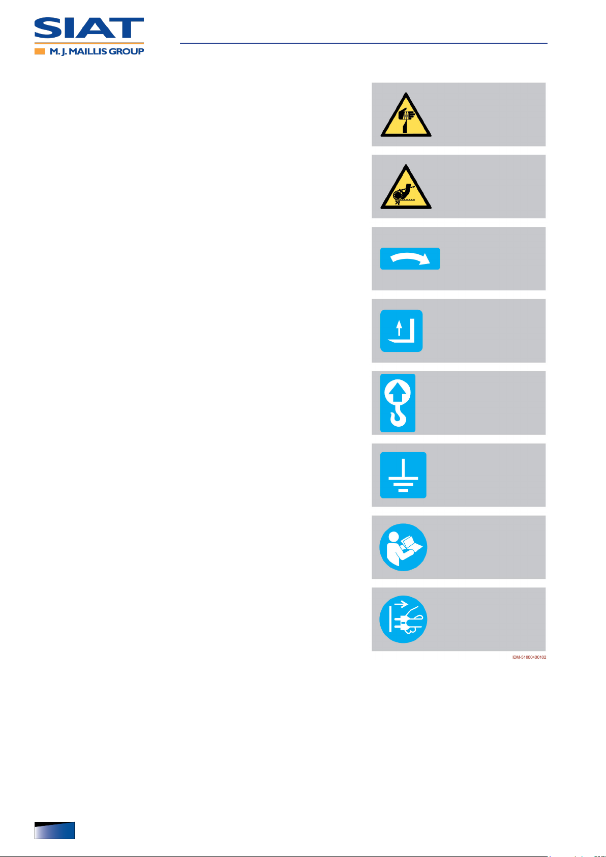
– Cutting hazard: danger sign warning not to come close to the cutting
parts with the upper limbs.
– Risk of entanglement: danger sign warning not to come close to the
moving parts with the upper limbs.
– Information Signal: indicates the required direction of rotation for
operation.
– Information Signal: indicates the lifting points for fork-type devices.
Safety information
– Information sign: it indicates the points where to attach the hooks of
the lifting device.
– Information Signal: indicates the earthing point.
– Information warning sign: read the operation and maintenance
manual carefully before performing any operations.
– Information signal: before performing any operation, disconnect the
power plug to avoid electric shock hazards.
12
English language Operation and maintenance manual
IDM 510-004-3
Technical Specications
general description of the machine
The semiautomatic robot series BeeWrap is a machine designed and built to stabilise palletised products with stretch lm.
– The products to be wrapped must be contained in packages (cases, containers for
liquids, etc.) having a regular shape or in any case, such as to allow for stable palletising.
– The containers of liquids or uids should be hermetically sealed and with suitable char-
acteristics to avoid spilling any content.
– To wrap loads, commercially available reels of stretch lm are used.
– The machine has been designed, built and equipped by applying integrated safety
principles.
– The machine is for professional use only and must be used in industrial-type settings
- factories or workshops.
– The premises must have no areas with gas and dust concentration levels that are po-
tentially explosive and/or at risk of re.
– The working area must be at (no slopes), compact and smooth to allow for easy and
safe movement of the machine.
– On request, the machine may be equipped with accessories, either when it is ordered
or later.
See “Optional Accessories” for further details.
– The machine must be used by one single operator ONLY, who must be trained and
capable of performing the work and be in suitable conditions.
– The operator must programme the wrapping cycle, start and monitor the operating
cycle and control the machine stops (pause, emergency, etc.).
– The operator must also change the lm reel, carry out the battery charge procedures
and the scheduled maintenance operations.
IDM 510-006-5
English languageOperation and maintenance manual
13

Technical Specications
Description of the main components
The image shows the main components and the list reports their description and
function.
14
English language Operation and maintenance manual
IDM 510-006-5

Technical Specications
A) Handlebar: control that drives the machine during the movement.
– The controls installed in the handlebar start the movement.
B) Feeler: it helps keeping the machine in contact with the perimeter of the load to be
wrapped.
C) Accumulator batteries: they supply the circuit and electric motors with power.
D) Battery charger: This electronic device is used to recharge the batteries C.
– To charge battery , connect the power supply cable to power outlet E.
– The charging status is shown on display of control panel E.
E) Electrical power outlet: it is used to connect battery charger to the power supply
network.
F) Control panel: it contains the devices to start and control all the operation functions.
G) Column: it is used for vertical movement of reel holding carriage H.
H) Reel holding carriage
– According to production requirements, in the ordering phase the machine can be
equipped with one of the listed carriages.
– Reel holder carriage (type M): suitable for wrapping, allows the operator to adjust the
lm tension manually using the ring nut of the mechanical brake.
– Reel-holder carriage (type FM): suitable for wrapping, allows the operator to adjust
the lm tension from the control panel.
– Reel-holder carriage (type LP): suitable for wrapping, with motorised lm pre-stretch-
ing and electronic tension adjustment from the control panel.
– Net-type reel holder carriage (type ): suitable for wrapping, allows the operator to
adjust the lm tension manually using the ring nut of the mechanical brake.
L) Document holder: it contains the use and maintenance manual.
IDM 510-006-5
English languageOperation and maintenance manual
15

Manufacturer and machine identication
The identication plate (pictured) is afxed directly to the machine.
– In addition to the references for iden-
tication provided by the Manufacturer, they also list all the essential
information for a safe operation.
A) Manufacturer identication
B) Space reserved for CE compliance
marking
C) Machine model
D) Machine type
E) Serial number
F) Serial number
G) Year of fabrication
H) Power supply voltage
Technical Specications
L) Electrical power consumption
M) Power supply frequency
N) Absorbed power
P) Power supply phases
16
English language Operation and maintenance manual
IDM 510-006-5

Technical Specications
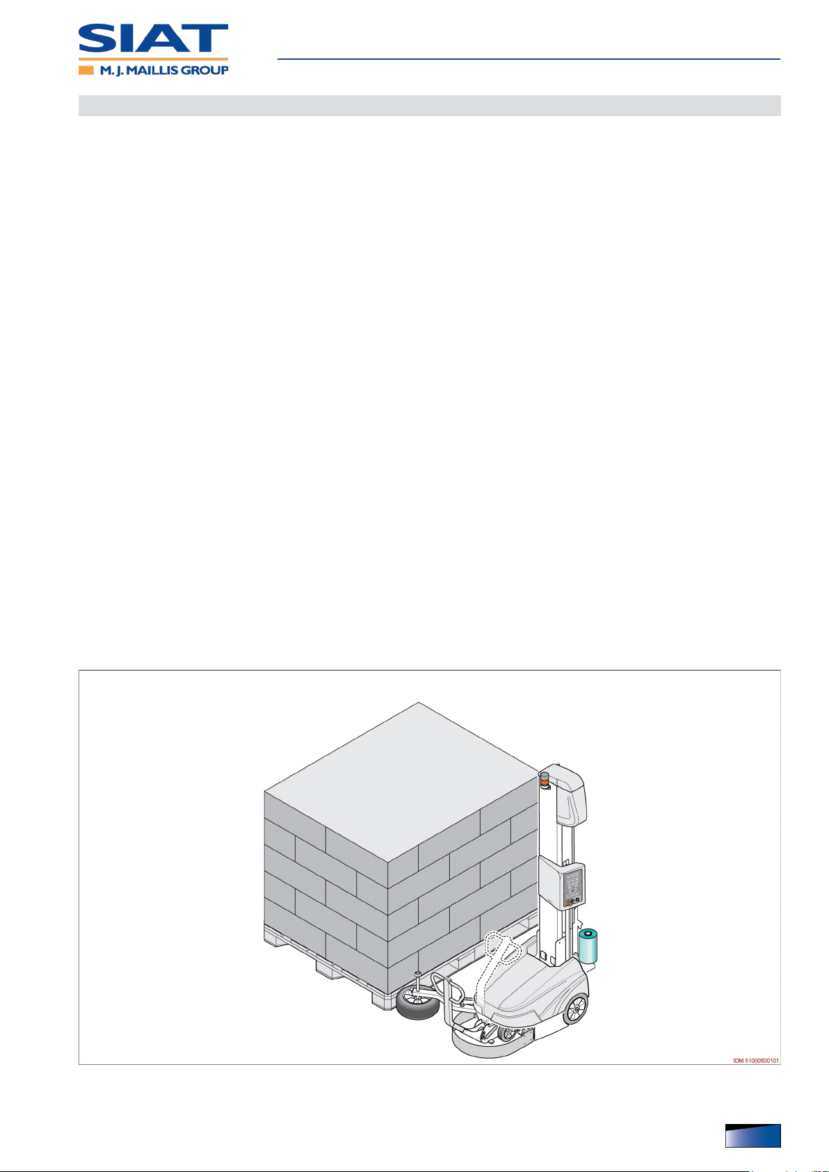
Cycle
The gures show the operating cycle with indication of the main operating areas.
Stage Ê
– Approach the machine to the pallet until touching the
feeler.
– Tie the trailing end of the lm to the base of the prod-
uct to be wrapped.
Stage Ë
– Start the wrapping cycle that will be performed based
on the previously set parameters.
– The machine moves clockwise around the product
and stops once it nishes wrapping it.
Stage Ì
– Manually cut the lm and cause it to adhere to the
wrapped product.
– The machine is ready for a new wrapping cycle.
IDM 510-006-5
English languageOperation and maintenance manual
17

Types of wrapping
The gure shows the types of wrapping available.
– Single wrapping: it starts at the base of the load to
be wrapped (with stabilisation wraps) and ends at
the top of the load, after completing the closing
wrapping.
– Move the reel carriage to fully lowered position from
the control panel to start a new wrapping.
The operator can decide whether to cut the lm
when the carriage is in the high position or in the
low position.
– Double wrapping: it starts at the base of the load to
be wrapped (with stabilisation wraps) and ends at
the top of the load.
– After completing the reinforcement at the top of the
load, the wrapping continues downwards and stops
after the closing wrapping.
Technical Specications
– Single wrapping with sheet feeder: it starts at the
base of the load to be wrapped (with stabilisation
wraps) and stops temporarily at the top of the load.
– After inserting the covering sheet the operator must
enable the control to restart the wrapping.
– After completing the upper reinforcement, the wrap-
ping stops.
– Move the reel carriage to fully lowered position from
the control panel to start a new wrapping.
The operator can decide whether to cut the lm
when the carriage is in the high position or in the
low position.
– Double wrapping with sheet feeder: it starts at the
base of the load to be wrapped (with stabilisation
wraps) and stops temporarily at the top of the load.
– After inserting the covering sheet the operator must
enable the control to restart the wrapping.
– After completing the reinforcement at the top of the
load, the wrapping continues downwards and stops
after the closing wrapping.
IDM 510-006-5
18
English language Operation and maintenance manual

Technical Specications
Residual risks
Residual risks are dened as: “Any risk that remains notwithstanding the safety solutions adopted and integrated during the design phase”.
– Each residual risk is signalled with a special sign. Some of them are applied close to
the areas where the risk is present, others are placed in an easily visible position.
– The list includes the residual risks that may persist on this type of machine.
– Risk of crushing body parts: do
not stay or pass through the operating area during wrapping.
– Risk of crushing body parts: pay
attention that there are no obstacles
during the manual reverse movement.
– Risk of crushing body parts and
lower limbs: do not stay within the
operating area while the reel holding
carriage is lowering.
IDM 510-006-5
English languageOperation and maintenance manual
19

– Risk of crushing upper limbs: do
not introduce or place upper limbs in/
next to any machine moving parts
during operation.
– The risk mainly relates to the area
between the sliding column and the
reel holding carriage.
Technical Specications
Incorrect uses that are reasonably expected
Improper use: reasonably foreseeable use different from what is specied in the use
manual, that may be caused by human behaviour.
– ONLY trained, documented and authorized Operators are allowed to use the machine.
– DO NOT use or allow other persons to use the machine for purposes and in ways dif-
ferent from what specied by the Manufacturer.
– NEVER use the tool if the scheduled maintenance interventions have not been carried
out accordingly
– DO NOT use the machine in unstable, uneven, sloping and unsuitably protected areas
to prevent the risk of capsizing or falling.
– DO NOT enable the wrapping cycle during road, rail or sea transport (even if the
means is not moving).
To be used on naval means, carefully assess its stability to be able to operate in
safe conditions.
– DO NOT use the machine in places that are at risk of re and / or explosion.
– Do not use the machine as a means to transport people or things.
– When the products are wrapped, the radius of action of the machine must be kept free
from people.
– DO NOT carry out any intervention when the machine is being operated. Stop the
machine and put it in safety condition before carrying out any intervention.
– DO NOT clean or wash the machine using aggressive products that may damage its
components.
– DO NOT leave the machine unattended during operation and DO NOT leave it at the
end of the work without stopping it to safety conditions.
20
English language Operation and maintenance manual
IDM 510-006-5
Technical Specications
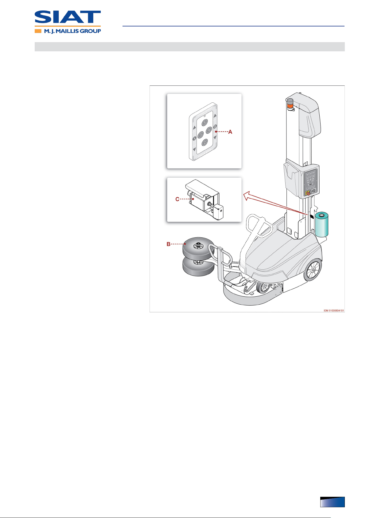
Optional Accessories
Some accessories designed to improve the performance and versatility of the machine are available from the manufacturer. This list contains a description of the
main ones.
A) Radio control: optional device that
is used as a remote control.
B) Double wheel feeler: compared to
the single wheel version, it increases
the contact with the perimeter of the
load to be wrapped.
C) Film cutting device: it cuts the lm
automatically at the end of wrapping
(only for reel holding carriage of type
“LP”).
IDM 510-006-5
English languageOperation and maintenance manual
21

Technical Specications
Description of the safety devices
The machine is equipped with safety devices that reduce the risks during the
man-machine interaction.
A) Emergency stop button: safety
control that, in case of an imminent
risk, stops all parts whose function
might constitute a risk.
See “Control description” for further
details.
B) Key selector switch: safety control
that connects and disconnects the
power supply of battery.
C) Fall arrest system: safety device
that prevents the risk of a fall of the
carriage in the event of lifting strap
breaking.
– System is equipped with spring de-
vice that locks reel holding carriage
in its position in case of failure of
belt.
D) Key selector: control to activate and
deactivate brake of the machine infeed electric motor.
– The key of control must be hand-
ed over to the maintenance technician in order to avoid any interference by non-authorised
personnel.
– When the machine stops and display
shows “b0”, it means that batteries
are completely exhausted.
Important
ONLY the maintenance technician is allowed to release the brake of the electric
motor in order to move the machine to the charge area.
E) Warning light (yellow light): safety device that signals the operating conditions of the
machine.
F) Audible warning device: safety device indicating the wrapping or machine conveying
process with manual control.
G) Fixed guard: safety device that prevents access to the parts whose operation may be
dangerous.
– The device is secured and it can be opened only by means of tools.
– Guard can be removed only when the machine is stopped under safe conditions and
must be installed before starting it.
H) Emergency bumper: safety device that stops the operation in emergency conditions,
in case of collision against an obstacle.
22
English language Operation and maintenance manual
IDM 510-006-5

Specications
Technical Specications
Table: Technical data of the machine
Description
Electric supply
The power supply specications are those shown in the identication plate applied to the machine.
Features of the machine (C=2100)
LxWxH (Length, width, height). mm 1600 x 1200 x 2410
E - Wrapping start value mm 50
F - Wrapping end value mm 2260
Weight (with acid-type batteries 90 A) kg 330
traverse speed m/min. 50 ÷ 80
Features of the machine (C=2600)
LxWxH (Length, width, height). mm 1600 x 1200 x 2910
E - Wrapping start value mm 50
F - Wrapping end value mm 2760
Weight (with acid-type batteries 90 A) kg 340
traverse speed m/min. 50 ÷ 80
Features of accumulator batteries
- Quantity no. 2
Batteries ¹)
- Current intensity (gel type)
- Current intensity (acid type) A 90
- Gel type (82 A) kg 27
Weight of every battery
- Gel type (105 A) kg 37
- Acid type (90 A) kg 29
Features of battery charger
See the technical specications on the identication plate of battery charger.
IDM 510-006-5
Characteristics of the load to be wrapped (C=2100)
AxBxC (Length, width, height).
- Min dimensions mm 400 x 500 x 600
- Max dimensions mm 6000 x 7000 x 2100
Maximum perimeter m 26
Unit of
measure-
ment
A 82
A 105
Value
English languageOperation and maintenance manual
23

Technical Specications
Description
Unit of
measure-
ment
- With film tensioning power from 2 kg kg 20
Minimum weight
- With film tensioning power from 6 kg kg 45
- With film tensioning power from 10 kg kg 55
Characteristics of the load to be wrapped (C=2600)
AxBxC (Length, width, height).
- Min dimensions mm 400 x 500 x 600
- Max dimensions mm 6000 x 7000 x 2600
Maximum perimeter m 26
- With film tensioning power from 2 kg kg 20
Minimum weight
- With film tensioning power from 6 kg kg 45
- With film tensioning power from 10 kg kg 55
Dimensions of lm reel
D - (Max.) diameter mm 250
d - Diameter of paperboard core (internal)mm mm 76
h - (Maximum height).mm mm 500
Film thickness µm 17 ÷ 23
Maximum weight kg 17
Environmental conditions
Maximum operating height (asl) m 1000
Relative humidity (detected at a temperature included between 20°C and 40°C) % 50
Ambient functioning temperature °C +5 ÷ 40
Environmental brightness LUX 150
Maximum level of noise dBa 72
¹) Accumulator batteries are installed as already ready for use (charged).
In case of shipment by air, the machine is delivered with non-installed batteries.
Value
24
English language Operation and maintenance manual
IDM 510-006-5
Technical Specications
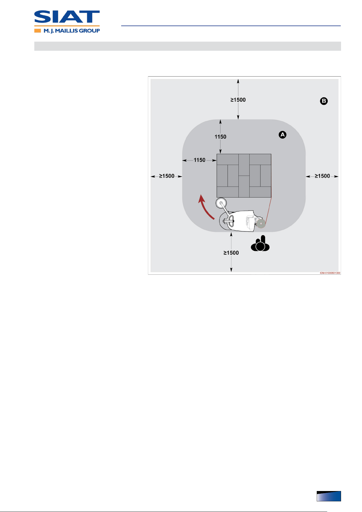
Description of outer areas
The gure shows different areas to be considered in the planning of the installation
area.
A) Machine working area
B) Perimeter area
IDM 510-006-5
English languageOperation and maintenance manual
25

Position of information and safety plates
The gure shows the position of the
signals applied on the machine.
– Please keep safety signs and infor-
mation legible and follow the instructions.
– Signals which are no longer legible
must be replaced and repositioned in
the same place of origin.
– For more details on the signs used,
refer to the section on “Safety signs
and information”.
Technical Specications
26
English language Operation and maintenance manual
IDM 510-006-5

Use and functioning
Recommendations on Operation and Use
– The machine must be used by one single operator ONLY, who must be trained and
capable of performing the work and be in suitable conditions.
– According to the type of operation to carry out, wear the Personal Protective Equip-
ment listed in the “Instructions for use” and that indicated by the Labour laws.
– Consult the user manual, in particular during the rst use, and make sure that you
fully understand its content.
– Find out the position and function of the controls and simulate some operations (in
particular start and stop) in order to acquire familiarity.
– The machine shall be used ONLY for the purposes and complying with the procedures
specied by the Manufacturer.
– Make sure that all the safety devices are properly installed and efcient.
– Ensure the area around the machine, especially the control post, is ALWAYS unob-
structed and in good condition to minimize the risks for the Operator.
– Keep the reel suitably relled to prevent to avoid interrupting the wrapping due to ab-
sence of lm.
IDM 510-006-5
English languageOperation and maintenance manual
27

Use and functioning
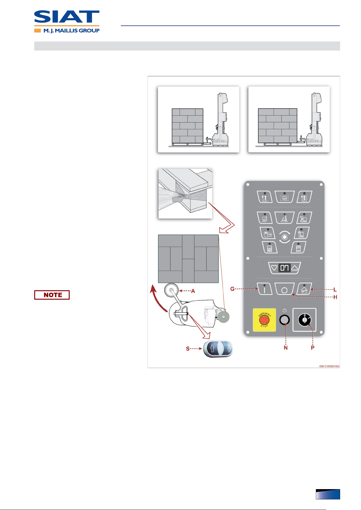
Control description
The illustration shows the main commands and their description and function are
listed.
A) Key: control that selects the type of
load to be wrapped (signalled by the
LED switching-on mode).
Press control repeatedly until you select the LED switching-on mode corresponding to the load to be wrapped.
– LED off: rectangular standard-sized
load to be wrapped.
– LED with steady light: circular load
to be wrapped.
– LED with ashing light: large-size
load to be wrapped.
B) Button: control that enables single
automatic wrapping (rise of the reel
holder carriage).
– Single automatic wrapping with-
out sheet feeder: press control
once (LED with solid light).
– Single automatic wrapping with
sheet feeder: press control twice
(blinking LED).
C) Button: control that enables double
automatic wrapping (rise and descent of the reel holder carriage).
– Double automatic wrapping with-
out sheet feeder: press control
once (LED with solid light).
– Double automatic wrapping with
sheet feeder: press control twice
(blinking LED).
D) Key: control for selecting the wrapping parameter to set and for enabling recipe selec-
tion.
– Recipe enabling: press control and keep it pressed (about 5 seconds).
– Parameter selection: press control repeatedly and release it when the LED corre-
sponding to the icon to be programmed turns on.
– Ê -
Setup of wrapping speed
– The number shown on display E refers to a value scale from 0 to 10.
– Ë - Setup of the size of the load to be wrapped
– The value is expressed in metre and it can be measured with a tolerance of ±10%.
28
English language Operation and maintenance manual
IDM 510-006-5

Use and functioning
– LED on with steady light combined with LED on with steady light of key A: program-
ming of the diameter of the load to be wrapped.
– Flashing LED: programming of the height of the load to be wrapped.
– Set up value 0 to allow special photocell to detect the height without measuring the
load to be wrapped.
– Ì - Setup of the speed of reel holding carriage
– LED on with steady light: programming of the lifting speed of the reel holding carriage.
– Flashing LED: programming of the lowering speed of the reel holding carriage.
– The number shown on display E refers to a value scale from 0 to 10.
– Í - Setup of the tension of lm (only for reel holding carriage of type FM - LP).
– The number shown on display E refers to a value scale from 0 to 99.
– Î - Setup of the detection delay of photocell
– Led on: programming time (in seconds) from the detection of the end of the load until
the stop of the reel holder carriage.
– Blinking LED: programming of the descent (in seconds) of the reel holder carriage in
order to allow the insertion of the protection sheet.
– Ï - Setup of the number of wrapping revolutions for bottom reinforcement.
– The number shown on display E refers to the number of wrapping revolutions to be
carried out for the reinforcing bands.
– Ð - Setup of the number of wrapping revolutions for upper reinforcement.
– The number shown on display E refers to the number of wrapping revolutions to be
carried out for the reinforcing bands.
E) Digital display: it displays different functions (value of the selected parameter, active
alarm, selected recipe, etc.).
– At the end of every wrapping cycle, display shows the charge level of accumulator
batteries.
After 30 seconds from the last control activation, the brightness intensity of display
decreases.
F) Keys: controls that increase or reduce the value shown in the display E.
– Controls (held pressed) are used to lift or lower reel holding carriage.
The operation mode is possible ONLY if the wrapping cycle is completed and/or all
LEDs are off.
G) Key: control to start the wrapping phase.
– LED on: function activated.
– LED on with ashing light: reel holding carriage not timed.
H) Key: control to stop the wrapping phase at a different point than the pre-set one.
L) Key: control that is used to reset the position of reel holding carriage.
IDM 510-006-5
– LED on: press control to perform the reset.
English languageOperation and maintenance manual
29

M) Emergency stop button: safety
control that, in case of an imminent
risk, stops all parts whose function
might constitute a risk.
– The control must stay “locked” until
all the normal operating conditions
have been restored.
– After having normalised running con-
ditions, unblock the button with a deliberate action to authorise restart.
N) Illuminated button (blue light):
control designed to activate electric
power supply.
– Control enabled only when selector
P is in position “1” (ON).
– Blue light off: activated power supply
line.
Use and functioning
– Blue light on: power supply deacti-
vated.
P) Key selector switch: safety control
that connects and disconnects the
power supply of battery.
– Position “1” (ON): power supply on
– Position “0” (OFF): power supply off
Q) Key selector: control to activate and
deactivate brake of the machine infeed electric motor.
– The key of control must be hand-
ed over to the maintenance technician in order to avoid any interference by non-authorised personnel.
– Position “0”: brake of electric motor activated and machine functions enabled.
– Control rotated to the right: brake of electric motor deactivated and machine functions
disabled.
– When the machine stops and display E shows “b0”, it means that batteries are com-
pletely exhausted.
Important
ONLY the maintenance technician is allowed to release the brake of the electric
motor in order to move the machine to the charge area.
R) Buttons: non-release controls that manually move the machine.
Controls are enabled only when reel holding carriage is in its lowest position.
30
English language Operation and maintenance manual
IDM 510-006-5

Use and functioning
S) Warning light (yellow light): safety device that signals the operating conditions of the
machine.
T) Audible warning device: safety device indicating the wrapping or machine conveying
process with manual control.
Z) Radio control: optional device that is used as a remote control.
Z1) Switching-on control
Z2) LED showing that device is on
Z3) Switching-off control
Z4) Control that starts wrapping
Z5) Control that interrupts the wrapping process in a point other than the pro-
grammed point.
IDM 510-006-5
English languageOperation and maintenance manual
31

Emergency stop and new start-up
Stop with activation of the emergency button
▀
1. In the presence of an imminent risk press emergency
button M.
– All moving devices immediately stop.
– The pilot light of button N turns on.
2. Identify the causes that have caused the stop.
3. Restore normal running conditions
Important
The recovery operations that are not within the operator’s eld of competence shall be carried out by authorised personnel and with recognised skills.
4. Manually cut the lm and cause it to adhere to the
wrapped product.
Use and functioning
Decide whether to remove or to leave the already
wrapped lm.
5. Unlock the emergency stop button with a voluntary ac-
tion.
6. Press the push-button N.
– The push-button lamp N shuts off.
7. Press key L.
8. Wait until reel holding carriage automatically reaches its end-of-cycle position.
9. Tie the trailing end of the lm to the base of the product to be wrapped.
10. Start the wrapping process.
Stop with activation of the emergency bumper
▀
– Operation stops automatically in emergency conditions when the bumper collides
against an obstacle.
– In case of emergency conditions, the pilot light of button N is on and audible warning
device is off.
1. Remove the obstacle.
2. Manually cut the lm and cause it to adhere to the wrapped product.
Decide whether to remove or to leave the already wrapped lm.
3. Press the push-button N.
– The push-button lamp N shuts off.
4. Press key L.
5. Wait until reel holding carriage automatically reaches its end-of-cycle position.
6. Tie the trailing end of the lm to the base of the product to be wrapped.
7. Start the wrapping process.
32
English language Operation and maintenance manual
IDM 510-006-5
Use and functioning
(Single or double) automatic wrapping
The gure shows the points of intervention and the description shows the procedures to be adopted.
1. Check whether the wrapping lm has
the same chemical-physical properties as that installed in the reel holder
carriage.
– If lm characteristics appear to be
different, consider whether you
should adjust the lm tension.
2. Rotate selector P to position “1”
(ON) in order to activate the battery
power supply.
– The pilot light of button N turns on.
3. Press the push-button N.
– The pilot light of button N turns off.
4. Use the buttons S to lean the roller
feeler A against the load to be
wrapped.
5. Before commissioning, check that
roller feeler is next to the upper surface of the pallet.
– If the pallet is smaller than the load to
be wrapped, roller feeler must be positioned on the lowest side of the
load.
The support area must be sufciently
regular to allow roller feeler to rotate
properly.
6. Tie the trailing end of the lm to the
base of the product to be wrapped.
7. Select and activate the recipe of interest.
See “Recipe management” for furcther details.
8. Press button G to start the wrapping cycle.
– If the LED of key L is ashing, press key L to move reel holding carriage to its end-of-
cycle position.
– When reel holding carriage is timed, the LED of key L turns off.
– To restart the wrapping cycle, press key G again.
– Audible warning device is activated to warn that the machine is operating.
IDM 510-006-5
– The machine stops as previously described, based on the selected type of wrapping.
English languageOperation and maintenance manual
33

Press button H to stop wrapping;
press button G to continue.
Wrapping will start at the point where
it has been stopped.
– Single mode: the wrapping stops
automatically with the reel holder
carriage at the upper side of the load.
Press button L to move reel holder
carriage to the start of the cycle (lower part).
– Double mode: the wrapping stops
automatically with the reel holder
carriage at the starting point (lower
side of the load).
9. Manually cut the lm and cause it to
adhere to the wrapped product.
Use and functioning
Important
Keep the reel suitably relled to prevent to avoid interrupting the wrapping due to absence of lm.
10. Use the buttons S to lean the roller
feeler A against the load to be
wrapped.
11. Press button G to start the wrapping
cycle.
– Audible warning device is activated
to warn that the machine is operating.
– The machine performs the new
wrapping and, at the end of the set
cycle, stops automatically.
12. Repeat the same steps for the rest of
the loads.
13. At the end of the working activity, adjust the buttons S to park the machine within the
battery charging area.
14. Carry out battery recharge (See “Charge of accumulator batteries”).
Normal stop
▀
– Make sure that the wrapping process has been completed.
– DO NOT control a machine stop if the wrapping cycle has not been completed.
– Manually cut the lm and cause it to adhere to the wrapped product.
– Remove the wrapped product.
– Rotate electric selector P to position “O” (OFF).
– The power supply of batteries is deactivated.
34
English language Operation and maintenance manual
IDM 510-006-5

Use and functioning
(Single or double) automatic wrapping with sheet feeder
The gure shows the points of intervention and the description shows the procedures to be adopted.
1. Check whether the wrapping lm has
the same chemical-physical properties as that installed in the reel holder
carriage.
– If lm characteristics appear to be
different, consider whether you
should adjust the lm tension.
2. Rotate selector P to position “1”
(ON) in order to activate the battery
power supply.
– The pilot light of button N turns on.
3. Press the push-button N.
– The pilot light of button N turns off.
4. Use the buttons S to lean the roller
feeler A against the load to be
wrapped.
5. Before commissioning, check that
roller feeler is next to the upper surface of the pallet.
– If the pallet is smaller than the load to
be wrapped, roller feeler must be positioned on the lowest side of the
load.
The support area must be sufciently
regular to allow roller feeler to rotate
properly.
6. Tie the trailing end of the lm to the
base of the product to be wrapped.
7. Select and activate the recipe of interest.
See “Recipe management” for furcther details.
8. Repeatedly press the button D until selecting the parameter Î.
9. Use one of controls F to dene the descent of reel holder carriage with regard to the
upper part of the product.
– The greater is the value, the greater is the movement of the reel holder carriage.
10. Press button G to start the wrapping cycle.
– If the LED of key L is ashing, press key L to move reel holding carriage to its end-of-
IDM 510-006-5
cycle position.
– When reel holding carriage is timed, the LED of key L turns off.
– To restart the wrapping cycle, press key G again.
English languageOperation and maintenance manual
35

– Audible warning device is activated
to warn that the machine is operating.
– The machine stops as previously de-
scribed, based on the selected type
of wrapping.
Press button H to stop wrapping;
press button G to continue.
Wrapping will start at the point where
it has been stopped.
– Single mode: the wrapping stops
automatically with the reel holder
carriage at the upper side of the load.
– Insert the covering sheet.
– Press the key G to complete the
wrapping of the covering sheet.
Press button L to move reel holder
carriage to the start of the cycle (lower part).
Use and functioning
– Double mode: the wrapping stops
automatically with the reel holder
carriage at the upper side of the load.
– Insert the covering sheet.
– Press key G.
– The machine completes the wrap-
ping cycle and stops automatically
with the reel holder carriage at the
lower side of the load.
11. Manually cut the lm and cause it to
adhere to the wrapped product.
Important
Keep the reel suitably relled to prevent to avoid interrupting the wrapping due to absence of lm.
12. Use the buttons S to lean the roller feeler A against the load to be wrapped.
13. Press button G to start the wrapping cycle.
– Audible warning device is activated to warn that the machine is operating.
– The machine performs the new wrapping and, at the end of the set cycle, stops auto-
matically.
14. Repeat the same steps for the rest of the loads.
15. At the end of the working activity, adjust the buttons S to park the machine within the
battery charging area.
16. Carry out battery recharge (See “Charge of accumulator batteries”).
36
English language Operation and maintenance manual
IDM 510-006-5

Normal stop
▀
– Make sure that the wrapping process has been completed.
– DO NOT control a machine stop if the wrapping cycle has not been completed.
– Manually cut the lm and cause it to adhere to the wrapped product.
– Remove the wrapped product.
– Rotate electric selector P to position “O” (OFF).
– The power supply of batteries is deactivated.
Use and functioning
IDM 510-006-5
English languageOperation and maintenance manual
37

Use and functioning
Setup of parameter values
The gure shows the points of intervention and the description shows the procedures to be adopted.
1. Press control D repeatedly and release it when the
LED corresponding to the icon to be programmed turns
on.
– The value of the selected parameter appears on dis-
play E.
2. Press one of buttons F to modify the value.
– With the parameter Ê selected: the number shown re-
fers to a value scale from 0 to 10.
– With parameter Ë selected: the displayed value refers
to the diameter or height of the load to be wrapped.
- Diameter of the load to be wrapped: from 0,8 to 0,9
metre
- Height of the load to be wrapped: from 0,6 to 2,6 metre
– With parameters Ì selected: the number shown refers
to a value scale from 0 to 9.
– With parameters Í selected: the number shown refers
to a value scale from 0 to 99.
– With the parameter Î selected: the number shown re-
fers to the time expressed in seconds (from 0 to 9.9).
– With the parameters Ï - Ð selected: the number
shown refers to the number of revolutions to be performed for the reinforcing wrappings (from 0 to 10).
38
English language Operation and maintenance manual
IDM 510-006-5

Use and functioning
Recipe management
The gure shows the points of intervention and the description shows the procedures to be adopted.
– The described procedures refer to how to modify and/
or activate a recipe.
Modifying a recipe
▀
1. Rotate selector P to position “1” (ON) in order to activate the battery power supply.
– The pilot light of button N turns on.
2. Press the push-button N.
– The pilot light of button N turns off.
– The number of the last used recipe appears on display
E.
3. Select the wrapping of interest by means of one of buttons B-C.
4. Keep button D pressed (about 5 seconds) in order to
enable programming.
5. Press one of buttons F to select the number of the rec-
ipe to be modied.
6. Set up all parameters of recipe one at a time.
7. Press control D repeatedly and release it when the
LED corresponding to the desired icon turns on.
– The value of the selected parameter appears on dis-
play E.
8. Press one of buttons F to modify the value.
– With the parameter Ê selected: the number shown refers to a value scale from 0 to
10.
– With parameter Ë selected: the displayed value refers to the diameter or height of the
load to be wrapped.
- Diameter of the load to be wrapped: from 0,8 to 0,9 metre
- Height of the load to be wrapped: from 0,6 to 2,6 metre
– With parameters Ì selected: the number shown refers to a value scale from 0 to 9.
– With parameters Í selected: the number shown refers to a value scale from 0 to 99.
– With the parameter Î selected: the number shown refers to the time expressed in
seconds (from 0 to 9.9).
– With the parameters Ï - Ð selected: the number shown refers to the number of rev-
olutions to be performed for the reinforcing wrappings (from 0 to 10).
IDM 510-006-5
English languageOperation and maintenance manual
39

Loading a recipe
▀
1. Rotate isolator switch P to position
“I” (ON) in order to activate the bat-
tery power supply.
– The pilot light of button N turns on.
2. Press the push-button N.
– The pilot light of button N turns off.
– The number of the last used recipe
appears on display E.
3. Use the buttons S to lean the roller
feeler A against the load to be
wrapped.
4. Tie the trailing end of the lm to the
base of the product to be wrapped.
5. Keep button D pressed (about 5 sec-
onds) in order to enable programming.
Use and functioning
6. Press one of buttons F to select the
number of the recipe to be loaded.
7. Press button G to start the wrapping
cycle.
– If the LED of key L is ashing, press
key L to move reel holding carriage
to its end-of-cycle position.
– When reel holding carriage is timed,
the LED of key L turns off.
– To restart the wrapping cycle, press key G again.
– Audible warning device is activated to warn that the machine is operating.
40
English language Operation and maintenance manual
IDM 510-006-5

Use and functioning
Recipe lock/unlock mode
The lock mode is used to avoid that the parameters of the stored recipes are
changed.
– The gure shows the points of intervention and the
description shows the procedures to be adopted.
1. Press and hold control H (about 7 seconds).
– Message “n. 0” appears on display E.
2. Press key D.
3. Press one of keys F until parameter “19” is displayed.
4. Press the key D to conrm.
– Display E shows message “c.9”.
5. Press key D.
6. Press one of keys F to select value “0” or “1”.
– Value “0”: recipes unlocked.
The parameters of the stored recipes can be changed.
– Value “1”: recipes locked.
The parameters of the stored recipes cannot be
changed.
7. Press the key D to conrm.
Recipe function “P0”
▀
– Recipe “P0” is used to programme the wrapping pro-
cess of a non-standard load, without changing the parameters of the programmed recipes.
– Recipe “P0” is enabled only through the recipe unlocking function.
To upload and change the recipe “P0” see “Recipe management”.
IDM 510-006-5
English languageOperation and maintenance manual
41
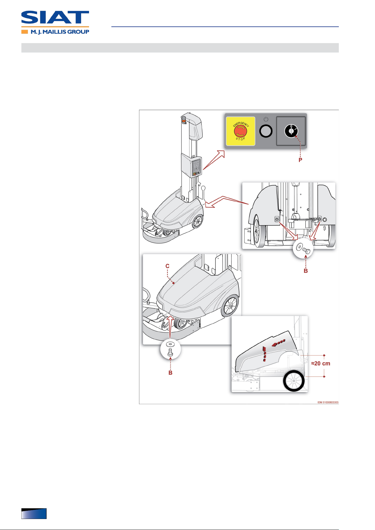
Use and functioning
Disassembly and reassembly of battery panel
This operation allows easy access to internal areas where the battery is installed.
– The operation must be carried out by the maintenance technician or by person-
nel with suitable competences, skills and knowledge.
– Make sure to full the required requirements in order to work under safe condi-
tions.
– The gure shows the points of in-
tervention and the description
shows the procedures to be
adopted.
1. Turn the selector P on position “O”
(OFF).
– The power supply of batteries is de-
activated.
2. Loosen screws B and remove them.
3. Slightly lift the rear side of panel C
and extract it forward to remove it.
Assembly of battery panel
▀
– Connect the front side of panel C to
the machine and lower it to starting
position.
– Introduce and tighten the screws B.
4. Rotate selector P to position “1”
(ON) in order to activate the battery
power supply.
42
English language Operation and maintenance manual
IDM 510-006-5

Recommendations for maintenance interventions
– The personnel authorized to carry out the ordinary maintenance must have qualied
expertise and specic skills in the eld of intervention.
– Any work on the electrical system must ONLY be performed by technicians with ac-
knowledged, eld-specic skills.
– Mark the intervention area and prevent access to the devices that, if activated, may
cause unexpected hazards and jeopardize the safety level.
– According to the type of operation to carry out, wear the Personal Protective Equip-
ment listed in the “Instructions for use” and that indicated by the Labour laws.
– Before carrying out any intervention, activate all the safety measures, and assess any
residual energy which may still be present.
– Carry out the interventions ONLY according to the modes recommended by the Man-
ufacturer in the “Instructions for use”.
– All operations must be carried out ONLY with suitable tools which shall be in good
condition, in order to avoid damaging any components and parts of the machine.
– At work completion, restore all the security conditions aimed to prevent and minimize
the risks during the human-machine interaction.
Maintenance
– At the end of operations check that there are no other tools or other material near the
moving parts or in dangerous areas.
– Refer to the Technical Assistance Service of the Manufacturer, in case interventions
not described in the “Instructions for use” are needed.
– In order to avoid safety hazards for the operators and nancial losses, follow not
only the recommendations but also the information in the SAFETY WARNINGS
section.
IDM 510-006-5
English languageOperation and maintenance manual
43

Scheduled maintenance intervals
Always keep the machine in optimum operating condition and carry out the routine
maintenance according to the intervals and procedures specied by the Manufacturer.
– In case of prolonged inactivity, carry out some maintenance operations in order to
preserve functionality and prevent further damages.
– After prolonged inactivity, carefully check that the operating functionality has remained
unaltered.
– A good maintenance will ensure a stable performance over time, longer working life
and constant compliance with the safety requirements.
Maintenance schedule
Every working day
Component Operation required Procedures to implement
Machine Control of emergency bumper
Control panel
Accumulator
batteries
Control of emergency stop
button
Charge
- Check the correct operation (See “Daily check of the safety
bumper”).
- Check the correct operation.
- Perform a full charge cycle at the end of the working activity (See
“Charge of accumulator batteries”).
Maintenance
Every 40 work hours (max 1 week)
Component Operation required Procedures to implement
- Remove any impurities with a plastic scraper.
- Clean with a soft cloth soaked in a non-flammable and non-
corrosive detergent.
- Properly dry the surfaces.
- Check this component for wear.
- Replace the belt in case it is excessively worn. (See “Replacing
the lifting belt of the carriage”).
- Clean the detection area of the photocell.
- Use a clean, dry (not abrasive) cloth.
Sliding column
Reel holding carriage
Cleaning of reel holding carriage
sliding guides
Check of lifting belt of the reel
holding carriage
Cleaning of the detection
photocell of the load to be
wrapped
Every 200 work hours (max 1 month)
Component Operation required Procedures to implement
GEL accumulator
batteries
ACID accumulator
batteries
Machine Control of emergency bumper
Cleaning
Cleaning
Check of electrolyte level
- Clean batteries
- Use a clean, dry (not abrasive) cloth.
- Clean batteries
- Use a clean, dry (not abrasive) cloth.
- Check the electrolyte level and, if necessary, top it up (See
“Maintenance of accumulator batteries (ACID)”).
- Check the correct operation (See “Monthly check of the safety
bumper”).
Every 5000 work hours (max 12 months)
Component Operation required Procedures to implement
Reel holding carriage
Machine Control of emergency bumper
44
English language Operation and maintenance manual
Check of vertical movement
wheels
- Check this component for wear.
- Replace the component, if it is worn out
- Check the correct operation (See “Yearly check of the safety
bumper”).
IDM 510-006-5

Daily check of the safety bumper
Att
The check is necessary to verify the efciency of the safety system and to maintain
a suitable efcacy level to prevent unexpected risks.
Important
The check must be carried out with the machine connected to the power supply, but
NOT MOVING.
– The gure shows the points of inter-
vention and the description shows
the procedures to be adopted.
1. Rotate selector P to position “1”
(ON) in order to activate the battery
power supply.
2. Press the push-button N.
3. Exercise a strong pressure onto
point A and check whether the pilot
light of button N is on.
Maintenance
– Microswitch W is damaged if the pilot
light of button N stays off.
4. Press the Reset key L.
5. Exercise a strong pressure onto
point B and check whether the pilot
light of button N is on.
– Microswitch Y is damaged if the pilot
light of button N stays off.
6. Press the Reset key L.
7. Replace the components, if dam-
aged.
ention
Warning
DO NOT keep using the machine if
you have not solved the detected defects and avoid the risk of faults or
unpredictable incidents.
– If the problem persists, please contact the Manufacturer’s Technical Service.
IDM 510-006-5
English languageOperation and maintenance manual
45

Monthly check of the safety bumper
Att
The check is necessary to verify the efciency of the safety system and to maintain
a suitable efcacy level to prevent unexpected risks.
– The operation must be carried out by the maintenance technician or by person-
nel with suitable competences, skills and knowledge.
– Make sure to full the required requirements in order to work under safe condi-
tions.
Important
The check must be carried out with the machine connected to the power supply, but
NOT MOVING.
– The gure shows the points of inter-
vention and the description shows
the procedures to be adopted.
1. Rotate selector P to position “1”
(ON) in order to activate the battery
power supply.
Maintenance
2. Press the push-button N.
3. Position the machine in the area A,
next to the load to be wrapped.
4. Position a test load or pallet in position C, at the distance and having the
weight that are specied in the image.
5. Adjust the control panel to set the
minimum travelling speed of the machine.
6. Press button G to start the wrapping
cycle.
– The machine begins to move forward
(audible warning device operating)
until emergency bumper collides
against test pallet.
– Due to collision, the machine must
stop under emergency conditions.
– In case of emergency conditions, the
pilot light of button N is on and audible warning device is off.
– If the machine does not stop under emergency conditions, one or both microswitches
W-Y are damaged.
The fault can be detected also in case the driving wheel continues rotating.
ention
Warning
If the machine does not stop, press emergency stop button M.
7. Press the Reset key L.
8. Replace the components, if damaged.
46
English language Operation and maintenance manual
IDM 510-006-5

Att
ention
Warning
DO NOT keep using the machine if you have not solved the detected defects and
avoid the risk of faults or unpredictable incidents.
9. Adjust the control panel to re-set the travelling speed of the machine.
– If the problem persists, please contact the Manufacturer’s Technical Service.
Maintenance
IDM 510-006-5
English languageOperation and maintenance manual
47
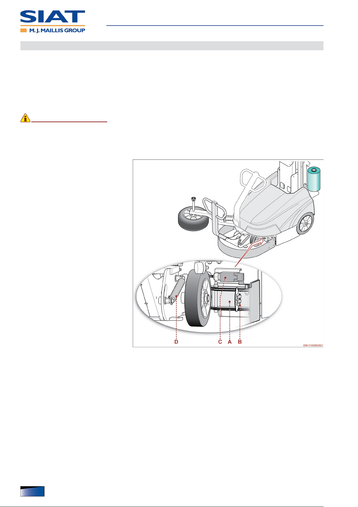
Yearly check of the safety bumper
The check is necessary to verify the efciency of the safety system and to maintain
a suitable efcacy level to prevent unexpected risks.
– The operation must be carried out by the maintenance technician or by person-
nel with suitable competences, skills and knowledge.
– Make sure to full the required requirements in order to work under safe condi-
tions.
Important
The check must be carried out with the machine NOT connected to the power supply.
DO NOT lift the machine from the ground to perform the checks.
– The gure shows the points of inter-
vention and the description shows
the procedures to be adopted.
1. Remove any residues from bumper
installation areas and from handlebar leverage points.
Maintenance
2. In area A, check that the levers that
activate the micro-switches move
freely and that they have no excessive clearance.
3. Check the efciency of the springs
B.
4. Check that all components of the
safety system are undamaged and
correctly tightened.
5. Screw all fasteners that are not correctly tightened.
6. Check the efciency of the mi-
cro-switches C.
7. Check the sensitivity level of the
safety bumper and that there are no
deformations, cuts or abrasions.
8. Check that the handlebar moves in a correct way.
9. Check the efciency of the springs D.
10. If you detect considerable irregularities, call the Technical Customer Service of the
manufacturer.
– Start the operation ONLY after restoring the normal working conditions of the safety
system.
48
English language Operation and maintenance manual
IDM 510-006-5

Recommendations for accumulator batteries
– Connect power supply cable of battery charger ONLY to a power outlet with suitable
features.
– DO NOT connect the power supply cable of battery charger , if the values do not com-
ply with those on the machine identication plate.
– When the machine is used for the rst time with new batteries, perform a full charge
cycle.
– NEVER interrupt the battery charge cycle before it reaches its maximum capacity.
– NEVER leave the batteries in the charge station longer than the required and absolute-
ly necessary time.
– DO NOT prolong the use of exhausted accumulator batteries.
– DO NOT use naked ames and DO NOT smoke during battery charge to avoid any
risk of explosion.
– DO NOT generate sparks while installing, removing, checking, etc. the batteries to
avoid any risk of explosion.
– In case of connection to auxiliary batteries or equipment DO NOT generate sparks to
avoid any risk of explosion.
Maintenance
Important
These precautions must been taken because a dangerous concentration of explosive gas mixtures can accumulate in the charge area.
– Connect the battery cables to those of the battery charger without inverting poles.
– DO NOT leave metallic objects between the battery poles and/or do not use them to
check the charge status to prevent the risk of any dangerous short-circuit.
– The recharging area must be arranged in ventilated premises, sheltered from weath-
ering agents and out of the operating areas.
– The installation of a charge area in a non-conforming place can generate a dangerous
concentration of explosive gas mixtures.
– Avoid discharging the batteries completely in order not to jeopardise their life cycle.
– Position the batteries in a suitable place.
The storage location should not be accessible to unauthorised persons, especially to
children, elderly and people with disabilities.
– Do not dispose of the old batteries in the environment. Carry out disposal according to
the laws in force.
IDM 510-006-5
English languageOperation and maintenance manual
49

Maintenance of accumulator batteries (GEL)
Perform the maintenance and charge of accumulator batteries to increase their life
and efciency.
– When the machine is used for the rst time with new batteries, perform a full charge
cycle.
– Once the charge process is completed, display shows a corresponding message “b9”.
– At the end of the work activity move the machine to the designated area and charge
the batteries.
– In the event of prolonged non-use, turn off the machine (isolator switch in OFF posi-
tion).
– In view of a prolonged period of inactivity, perform a full charge cycle of the batteries.
– If the period of inactivity exceeds 30 days, perform a full charge cycle every month.
– Gel batteries contain a gelatinous electrolyte that shall be NEVER added.
Maintenance of accumulator batteries (ACID)
Maintenance
Perform the maintenance and charge of accumulator batteries to increase their life
and efciency.
– When the machine is used for the rst time with new batteries, perform a full charge
cycle.
– Once the charge process is completed, display shows a corresponding message “b9”.
– Fill up the batteries ONLY with distilled water.
– DO NOT ll up with batteries with sulphuric acid or other types of liquid.
– The electrolyte level must be 15 mm above the elements of battery.
– When the electrolyte level is just above the elements, relling must be carried out
ONLY when the batteries are completely charged.
– When the electrolyte level is below the elements, relling must be carried out ONLY
when the batteries are completely exhausted.
In the batteries are completely exhausted, use the machine until they are completely
discharged.
– The electrolyte contained in the batteries is a highly corrosive substance.
– In case of contact with the skin and the eyes, immediately wash with plenty of water
and offer the necessary medical treatment.
– In case of contact with clothing or with painted surfaces, immediately wash with plenty
of water.
– At the end of the work activity move the machine to the designated area and charge
the batteries.
– In the event of prolonged non-use, turn off the machine (isolator switch in OFF posi-
tion).
– In view of a prolonged period of inactivity, perform a full charge cycle of the batteries.
– If the period of inactivity exceeds 15 days, perform a full charge cycle every 2 weeks.
– DO NOT leave the machine powered when the batteries are at their minimum charge
level to avoid that it gets completely exhausted.
– Repeated full discharge of the batteries will greatly reduce their life cycle.
– Accumulator batteries shall NOT stay exhausted for more than 48 hours.
50
English language Operation and maintenance manual
IDM 510-006-5

Charge of accumulator batteries
The accumulator batteries must be charged at the end of each working day or when
display E shows message “b1”.
– When message “b1” is displayed,
the wrapping cycle stops automatically.
– The battery has sufcient charge lev-
el in order to reach the recharge
area.
– The residual charge that remains in
the battery is important to safeguard
its lifespan.
Important
Carry out recharge immediately to
avoid that the level falls below the
minimum threshold.
Maintenance
When the machine stops and display
E shows “b0”, it means that batteries
are completely exhausted.
ONLY the maintenance technician is
allowed to release the brake of the
electric motor in order to move the
machine to the charge area.
Transfer shall be carried out ONLY on
at areas without any depression
and/or unevenness.
Important
The recharging area must be arranged in ventilated premises, sheltered from weathering agents and
out of the operating areas.
– In case of prolonged inactivity, periodically perform a full recharge of the battery.
– Gel battery: charge every month
– Acid battery: recharge every 2 weeks
– For further details on the batteries, see the Manufacturer’s information.
– Charge the battery as follows.
1. Manually cut the lm and cause it to adhere to the wrapped product.
2. Adjust the buttons S to park the machine within the battery charging area.
3. Turn the selector P on position “O” (OFF).
Important
DO NOT carry out the recharge with the control P switched ON to prevent the electric components from being damaged by overcurrents.
IDM 510-006-5
When display E shows message “b0”, the maintenance technician must release the
brake to move the machine to the charge area.
Transfer shall be carried out ONLY on at areas without any depression and/or unevenness.
English languageOperation and maintenance manual
51

4. Check that the power supply line has
the same specications as those
stated in the identication plate.
5. Connect the power cable U to the
socket T.
– Once the charge process has start-
ed, display E shows a corresponding
message “b0”.
Display E shows (alternatively) message and graphic bar that show the
charge level.
– Once the charge process is complet-
ed, display E shows a corresponding
message “b9”.
6. Disconnect cable U from electric
socket T.
Maintenance
7. Rotate selector P to position “1”
(ON) in order to activate the battery
power supply.
52
English language Operation and maintenance manual
IDM 510-006-5

Problems, causes, remedies
The table shows the list of faults that can occur during the standard operation and
it highlights possible remedies.
Table: Operation failures
Problem Cause Remedy
The display shows the message
“b0” - “b1”.
The machine does not start
The reel holder carriage raises but
does not stop at the top of the load
to be wrapped.
The ends of the load are wrapped
with an excessive amount of
reinforcing bands.
The lm is too tightly stretched or
too loose.
The machine stops with the reel
holding carriage not correctly
positioned.
The noise level is too high.
Reel holding carriage jogging
motion.
The operating functions cannot be
started by using the radio control
The batteries do not recharge
completely.
Flat battery
Emergency stop button pressed
The bumper hit an obstacle within the
working area
Flat battery
The photocell did not detect the load
to be wrapped
Top reinforcing band quantity not
correctly set
Bottom reinforcing band quantity not
correctly set
Tension of lm not properly adjusted
Presence of residues or dust on the
reel holding carriage sliding guides
There is an obstacle under the reel
holder carriage.
Braking or excessive wear of the reel
holder carriage lifting belt
The gearmotor that moves the reel
holding carriage is faulty
The gearmotor that starts the wheels
is faulty
Presence of residues or dust on the
reel holding carriage sliding guides
Faulty radio control - Check the functionality of the component.
Faulty batteries - Replace the component.
Faulty battery charger - Replace the component.
- Carry out battery recharge (See “Charge of
accumulator batteries”).
- See “Stop with activation of the emergency
button”
- See “Stop with activation of the emergency
bumper”
- Carry out battery recharge (See “Charge of
accumulator batteries”).
- Check the functionality of the component.
- The component must be adjusted (See
“Sensitivity adjustment for the product to be
wrapped detection photocell”).
- Modify the programming (See “Setup of
parameter values”).
- Modify the programming (See “Setup of
parameter values”).
- Adjust the tension of film (See “Tension
adjustment of film”).
- Release the safety brake of the reel holder
carriage and remove the residues.
Use brushed with soft plastic bristles.
- Release the safety brake of the reel holder
carriage and remove the obstacle.
- Release the safety brake of the reel holder
carriage and replace the component (See
“Replacing the lifting belt of the carriage”).
- Check the functionality of the component.
- Check the functionality of the component.
- Remove any residues.
Use brushed with soft plastic bristles.
Maintenance
IDM 510-006-5
English languageOperation and maintenance manual
53

Alarm message table
no. Type of failure Remedy
Machine alarms
Sensor does not detect the shifting of
01
machine.
(Lower and upper) sensors do not detect the
02
end of stroke of the reel holding carriage.
The carriage drive chain is not correctly
05
tensioned.
The photocell does not detect any load to be
06
wrapped.
The lm reel is exhausted (Only for reel
08
holding carriages of type LP).
The inverter parameters are not properly set
10
up.
The activation of the inverter electric power is
11
not correctly enabled.
The electric motor is damaged due to a short
12
circuit.
The heat protection is damaged because of
13
the overheating of the electric motor.
Communication was interrupted because of an
17
internal error.
- Check the connections and/or the position of sensor.
- Press control N to silence the alarm.
- Check the connections and/or the position of sensors.
- Press control N to silence the alarm.
- Make sure that the reel holding carriage can move freely and without
obstacles.
- Check the connections and/or the position of the photocells.
- Press control N to silence the alarm.
- Control L lights up.
- Press control L.
- Reel holding carriage moves upwards and then it moves downwards
again in order to phase the operating units.
- Make sure that the load to be wrapped is properly positioned.
- Check the connections and/or the position of the photocell.
- Press control N to silence the alarm.
- Replace reel (See “Film Coil Feeding”).
Machine shifting inverter alarms
- Contact the Manufacturer’s Technical Assistance Service.
- Contact the Manufacturer’s Technical Assistance Service.
- Contact the Manufacturer’s Technical Assistance Service.
- Let the motor cool down.
- Press control N or deactivate and re-activate power (even more than
once) to silence the alarm.
- Replace electronic board if the alarm persists.
- Contact the Manufacturer’s Technical Assistance Service.
Maintenance
54
English language Operation and maintenance manual
IDM 510-006-5

no. Type of failure Remedy
Reel holder carriage inverter alarms
The inverter parameters are not properly set
20
up.
The activation of the inverter electric power is
21
not correctly enabled.
The electric motor is damaged due to a short
22
circuit.
- Contact the Manufacturer’s Technical Assistance Service.
- Contact the Manufacturer’s Technical Assistance Service.
- Contact the Manufacturer’s Technical Assistance Service.
- Let the motor cool down.
The heat protection is damaged because of
23
the overheating of the electric motor.
- Press control N or deactivate and re-activate power (even more than
once) to silence the alarm.
- Replace electronic board if the alarm persists.
Communication was interrupted because of an
27
internal error.
- Contact the Manufacturer’s Technical Assistance Service.
Reel holding carriage (type LP) inverter alarms
The inverter parameters are not properly set
30
up.
The activation of the inverter electric power is
31
not correctly enabled.
The electric motor is damaged due to a short
32
circuit.
- Contact the Manufacturer’s Technical Assistance Service.
- Contact the Manufacturer’s Technical Assistance Service.
- Contact the Manufacturer’s Technical Assistance Service.
- Let the motor cool down.
The heat protection is damaged because of
33
the overheating of the electric motor.
- Press control N or deactivate and re-activate power (even more than
once) to silence the alarm.
- Replace electronic board if the alarm persists.
Communication was interrupted because of an
37
internal error.
- Contact the Manufacturer’s Technical Assistance Service.
Battery charger alarms
40 Battery charger is damaged.
Communication was interrupted because of an
47
internal error.
- Remove hood , disconnect battery charger and then reconnect it.
- If the alarm persists, replace battery charger.
- Contact the Manufacturer’s Technical Assistance Service.
Maintenance
IDM 510-006-5
English languageOperation and maintenance manual
55

How to adjust the feeler
Before commissioning, check that roller feeler is next to the upper surface of the
pallet.
– If the pallet is smaller than the load to be wrapped, roller feeler C must be positioned
on the lowest side of the load.
The support area must be sufciently regular to allow roller feeler to rotate properly.
– The solution is valid also for the double wheel feeler.
– The gure shows the points of inter-
vention and the description shows
the procedures to be adopted.
1. Move the machine to match the load
to be wrapped.
2. Rotate selector P to position “1”
(ON) in order to activate the battery
power supply.
Maintenance
– The power supply of batteries is de-
activated.
3. Loosen the screw A, take the wheel
C to the desired height, and then
tighten the screw.
4. Regulate the pressure of wheel C on
the pallet by means of tie rod D, according to the wrapping speed and
the load dimensions.
5. Perform a practical test to check
whether the operation is correct and,
if necessary, repeat it.
56
English language Operation and maintenance manual
IDM 510-006-5
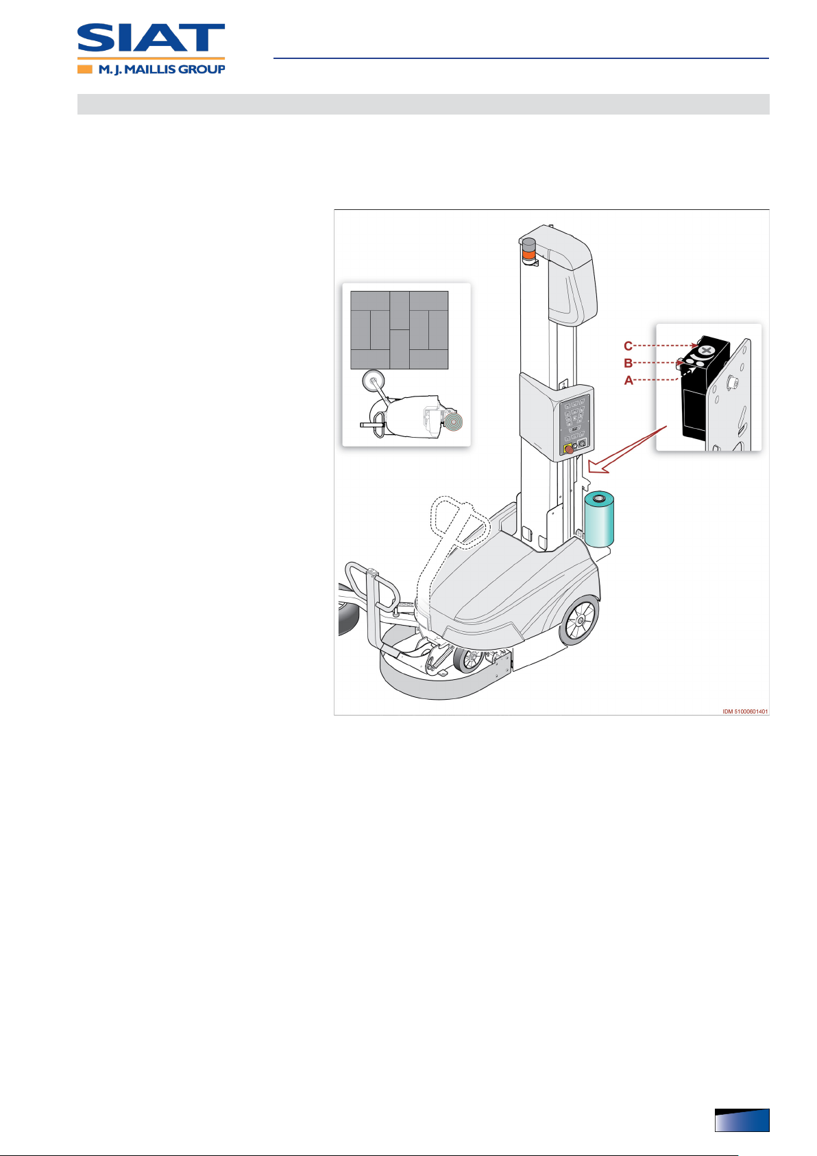
Sensitivity adjustment for the product to be wrapped detection photocell
The operation must be carried out by the maintenance technician or by personnel
with suitable competences, skills and knowledge.
Make sure to full the required requirements in order to work under safe conditions.
– The sensitivity adjustment is required
when the photocell does not detect
the presence of the load to be
wrapped.
1. Lean the roller feeler against the pal-
let containing the product (see gure).
2. Check if the photocell detects the
load to be wrapped.
– When pilot light B turns on (yellow
light), it means that the load to be
wrapped has been detected.
Maintenance
– When the light B is off, slowly rotate
the control C until the indicator light
illuminates.
– The light A lighting up (green light)
indicates that the photocell is powered.
IDM 510-006-5
English languageOperation and maintenance manual
57

Replacing the lifting belt of the carriage
The operation must be carried out by the maintenance technician or by personnel
with suitable competences, skills and knowledge.
Make sure to full the required requirements in order to work under safe conditions.
– The gure shows the points of in-
tervention and the description
shows the procedures to be
adopted.
1. Turn the selector A on position “O”
(OFF).
– The power supply of batteries is de-
activated.
2. Remove reel.
3. Unhook tie rod K.
4. Completely rotate handlebar B.
Maintenance
5. Remove the fastening elements and
remove the component C.
6. Install support D and x it with screw
D1.
7. Attach the column G to a lifting de-
vice.
8. Loosen screws E on both sides.
9. Slightly loosen screws F on both
sides.
10. Bring the column to a horizontal position.
11. Tighten the screws F on both sides.
12. Remove the lifting device.
13. Remove the fastening elements H
and remove the component L.
14. Slip out pin M.
15. Partially remove the reel holder car-
riage to reach the fastening elements
N.
Remove the cable bracket if necessary.
16. Remove the fasteners N.
17. Remove the bushing P and remove
the damaged belt Q.
18. Insert the bushing P in the new belt.
19. Secure the end of the belt (with bushing) by means of the fastening elements N.
20. Remount the reel holder carriage.
58
English language Operation and maintenance manual
IDM 510-006-5

Remount the cable bracket if previously removed.
21. Lead the belt over the roller R.
22. Insert the pin M to connect the end of
the belt to the pulley S.
23. Install the component L and lock it in
place with the fastening elements H.
24. Keep the belt taut and move the reel
holder carriage to match the base of
the column.
25. Loosen the screws F on both sides.
26. Attach the column G to a lifting de-
vice.
27. Lift the column G to its vertical posi-
tion.
Maintenance
28. Tighten the screws E on both sides.
29. Tighten the screws F on both sides.
30. Remove the lifting device.
31. Loosen screw D1 and remove sup-
port D.
32. Install the component C and lock it in
place with the fastening elements.
33. Hook tie rod K.
– At the end of operations, check
that there are no tools or other
material near the moving parts or
in dangerous areas.
IDM 510-006-5
English languageOperation and maintenance manual
59
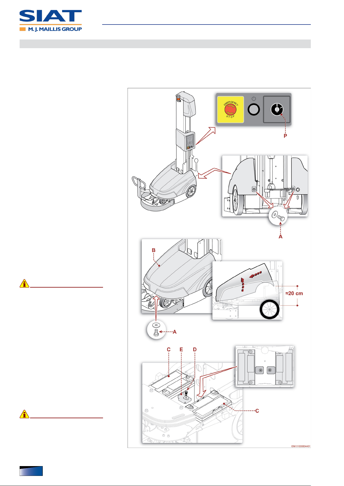
Battery replacement
Personnel having suitable experience, knowledge and skills must carry out the intervention.
Make sure to full the required requirements in order to work under safe conditions.
– The gure shows the points of inter-
vention and the description shows
the procedures to be adopted.
1. Wear the suitable personal protective equipment (gloves and shoes) to
avoid any abrasion and/or crushing
hazard.
2. Turn the selector P on position “O”
(OFF).
– The power supply of batteries is de-
activated.
Maintenance
3. Loosen screws A and remove them.
4. Slightly lift the rear side of panel B
and extract it forward to remove it.
5. Disconnect clamps from accumulator batteries C.
6. Loosen screwsD and remove brack-
ets E.
7. Extract accumulator batteries C
8. Insert new accumulator batteries in
its original position.
Important
Replace the components ONLY with
ORIGINAL SPARE PARTS.
9. Install brackets E and x it with
screws D.
10. Connect clamps to the corresponding poles of batteries.
11. Connect the front side of panel B to
the machine and lower it to starting
position.
12. Introduce and tighten the screws A.
13. Rotate selector P to position “1”
(ON) in order to activate the battery
power supply.
Important
When the batteries are used for the
rst time, perform a full charge cycle.
60
English language Operation and maintenance manual
IDM 510-006-5

Machine Disposal and Scrapping
Machine dismantling
▀
– Disconnect the supplies form the energy sources (electrical, pneumatic, etc.) in order
to prevent any restart.
– Carefully drain the systems containing hazardous substances, according to the appli-
cable regulations on safety at work and environmental protection.
– Position the machine in a place that is not easily accessible by non authorised people.
Machine Scrapping
▀
– Carefully drain the systems containing hazardous substances, according to the appli-
cable regulations on safety at work and environmental protection.
– The machine is to be scrapped at the authorized centres by skilled personnel equipped
with all the necessary means to operate in safety conditions.
– The personnel carrying out the scrapping of the machine must identify any residual
energy and implement a “safety plan” to avoid any unexpected hazard.
– The components must be selected based on the chemical and physical characteristics
of their materials and disposed of separately according to the regulations in force.
Maintenance
IDM 510-006-5
English languageOperation and maintenance manual
61

Reel holding carriage (M)
Main components
▀
A) Structure: it is equipped with wheels
for vertical shifting of carriage on column.
– In the structure a fall arrest system is
installed, which stops the carriage in
case of lifting belt failure.
B) Reel holder: it is equipped with
braking system to avoid reel unwinding.
C) Roller: designed to tension the lm.
– Roller is coated with inserts in order
to ensure lm pulling during wrapping.
D) Roller (idle)
Reel holding carriages
E) Ring: device used to adjust the ten-
sion of the lm.
F) Lever: device used to disengage the
roller C.
G) Photocell: it detects the presence
and the height of the load to be
wrapped in order to stop the upward
movement of reel holding carriage.
– On request, a “black” version of the
photocell can be supplied, specically designed to detect wrapped items
or products with a prevalence of dark
surfaces.
On request, the reel holder carriage can be supplied in version for net-type wrapping.
62
English language Operation and maintenance manual
IDM 510-006-5

Film Coil Feeding
▀
1. Lower the reel holding carriage until
its endstroke.
2. Lift the lever F to its vertical position.
3. Remove the cardboard core of the
reel.
4. Insert the new reel.
Check whether the wrapping lm has
the same chemical-physical properties as that installed in the reel holder
carriage.
If lm characteristics appear to be
different, consider whether you
should adjust the lm tension.
5. Insert lm according to the required
direction of the adhesive size.
Reel holding carriages
Important
In order to avoid transferring impurities to the surfaces of the guiding rollers, discard the outer wrapping lm layer on the reel.
6. Tie the trailing end of the lm to the base of the product to be wrapped.
7. Start wrapping.
8. Lower the lever F to horizontal position after performing at least one wrap.
Tension adjustment of lm
▀
– The operation is necessary to adjust the lm tension on the load to be wrapped.
1. Lower the reel holding carriage until
its endstroke.
2. Lift the lever F to its vertical position.
3. Start wrapping.
4. Lower the lever to horizontal position
after performing at least one wrap.
5. Adjust the lm tension via the ring E.
– Clockwise: the value increases.
– Anti-clockwise: the value decreas-
es.
IDM 510-006-5
English languageOperation and maintenance manual
63

Reel holding carriages
Cleaning and replacement of brake disc
▀
– The operation must be carried out by the maintenance technician or by person-
nel with suitable competences, skills and knowledge.
– Make sure to full the required requirements in order to work under safe condi-
tions.
– This service should be carried out with the reel holding carriage lowered and the
machine safely at a stop.
1. Lift the lever A to its vertical position.
2. Remove the fastening elements and
remove the lever.
3. Remove in a sequence the components B-C-D-E.
4. Clean the contact surfaces of the
brake discs E-F.
5. Check the wear level of the friction
material of the disc E.
– In the case of excessive wear, re-
place the component.
6. Install the disc E with the friction ma-
terial facing downwards.
7. Install in a sequence the components D-C-B.
8. Engage the lever A in a vertical posi-
tion and insert the fastening elements.
9. Lower the lever to its horizontal position.
– At the end of operations, check
that there are no tools or other
material near the moving parts or
in dangerous areas.
64
English language Operation and maintenance manual
IDM 510-006-5
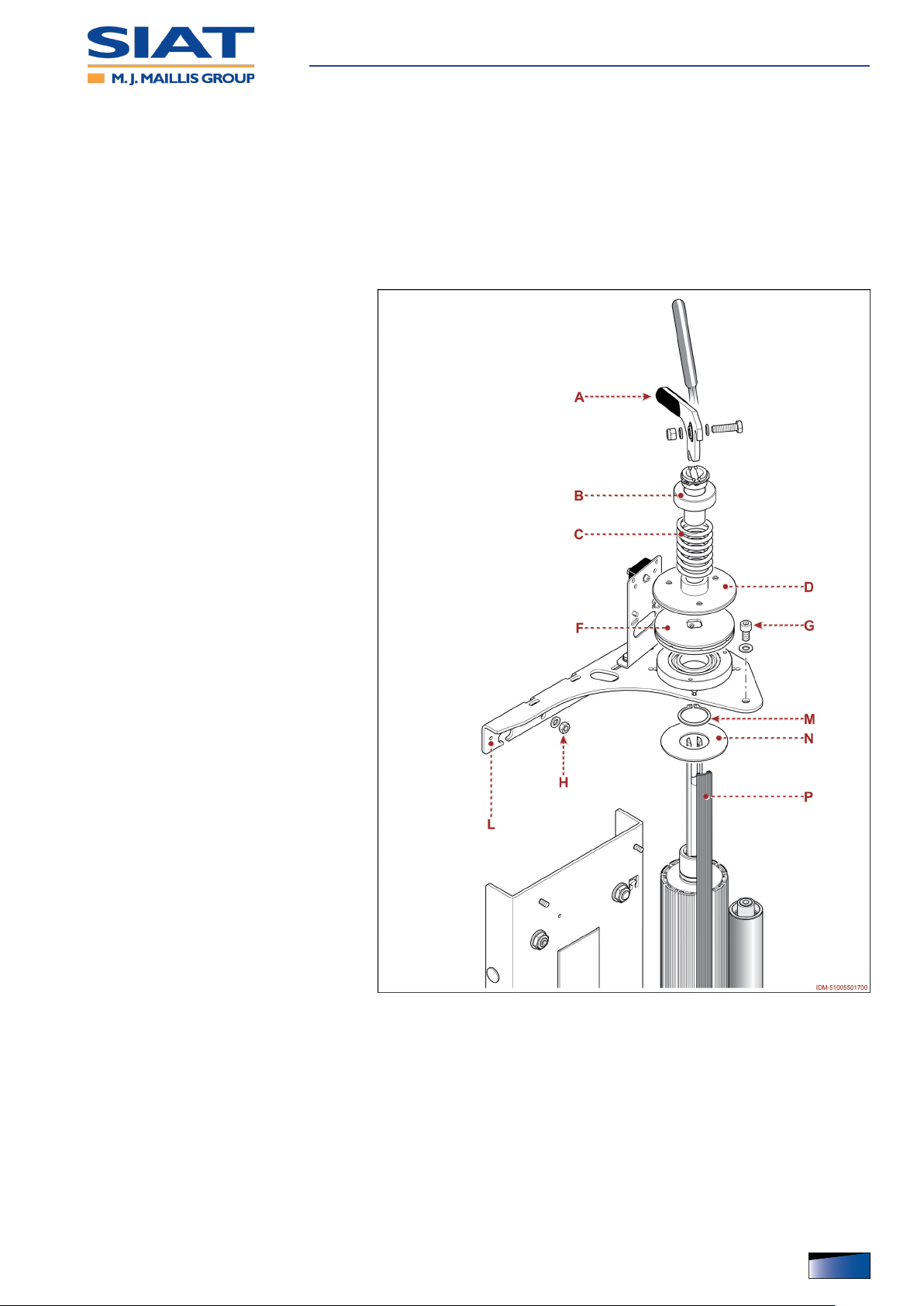
Reel holding carriages
Replacing the outer surface of roller
▀
– The operation must be carried out by the maintenance technician or by person-
nel with suitable competences, skills and knowledge.
– Make sure to full the required requirements in order to work under safe condi-
tions.
– This service should be carried out with the reel holding carriage lowered and the
machine safely at a stop.
1. Lift the lever A to its vertical position.
2. Remove the fastening elements and
remove the lever.
3. Remove in a sequence the components B-C-D.
4. Remove the component F.
5. Unscrew screw G.
6. Unscrew the nuts H.
7. Remove the plate L.
8. Remove stop ring M.
9. Remove the component N.
10. Remove all the external cylinder sur-
face inserts P, one at a time.
11. Thoroughly clean the grooves of the
roller.
12. Insert in a sequence, one at a time,
all the new external cylinder surface
inserts.
13. Install component N.
14. Reinstall the retainer ring M.
15. Fit back the plate L and x it with the
nuts H without tightening.
16. Insert screw G and tighten it.
17. Adjust the position of the plate L and
tighten the nuts H.
18. Install component F.
19. Install in a sequence the compo-
nents D-C-B.
20. Engage the lever A in a vertical posi-
tion and insert the fastening elements.
21. Lower the lever to its horizontal position.
– At the end of operations, check that there are no tools or other material near the
moving parts or in dangerous areas.
IDM 510-006-5
English languageOperation and maintenance manual
65

Reel holding carriage (FM)
Main components
▀
A) Structure: it is equipped with wheels
for vertical shifting of carriage on column.
– In the structure a fall arrest system is
installed, which stops the carriage in
case of lifting belt failure.
B) Reel holder: it is equipped with
braking system to avoid reel unwinding.
C) Roller: designed to tension the lm.
– Roller is coated with inserts in order
to ensure lm pulling during wrapping.
D) Roller (idle)
Reel holding carriages
E) Electromechanical brake: device
that adjusts the tension of the lm.
F) Photocell: it detects the presence
and the height of the load to be
wrapped in order to stop the upward
movement of reel holding carriage.
– On request, a “black” version of the
photocell can be supplied, specically designed to detect wrapped items
or products with a prevalence of dark
surfaces.
66
English language Operation and maintenance manual
IDM 510-006-5

Film Coil Feeding
▀
1. Lower the reel holding carriage until
its endstroke.
2. Remove the cardboard core of the
reel.
3. Insert the new reel.
Check whether the wrapping lm has
the same chemical-physical properties as that installed in the reel holder
carriage.
If lm characteristics appear to be
different, consider whether you
should adjust the lm tension.
4. Insert lm according to the required
direction of the adhesive size.
Important
Reel holding carriages
In order to avoid transferring impurities to the surfaces of the guiding
rollers, discard the outer wrapping lm layer on the reel.
5. Tie the trailing end of the lm to the base of the product to be wrapped.
6. Start wrapping.
Tension adjustment of lm
▀
– The operation is necessary to adjust the lm tension on the load to be wrapped.
1. Repeatedly press the button D until selecting the pa-
rameter Í.
– LED turns on.
2. Adjust the lm tension via the controls F.
IDM 510-006-5
English languageOperation and maintenance manual
67

Reel holding carriages
Cleaning and replacement of brake disc
▀
– The operation must be carried out by the maintenance technician or by person-
nel with suitable competences, skills and knowledge.
– Make sure to full the required requirements in order to work under safe condi-
tions.
– This service should be carried out with the reel holding carriage lowered and the
machine safely at a stop.
1. Remove the fastening elements and
remove the actuator A.
2. Remove in a sequence the components B-C-D-E-F.
3. Clean the matching surfaces of the
friction discs D-F.
4. Check the wear level of the friction
material of the disc E.
– In the case of excessive wear, re-
place the component.
5. Install in a sequence the components F-E-D-C-B.
6. Install the component A and lock it in
place with the fastening elements.
7. Adjust brake.
See “Adjustment of brake” for furjther details.
– At the end of operations, check
that there are no tools or other
material near the moving parts or
in dangerous areas.
68
English language Operation and maintenance manual
IDM 510-006-5
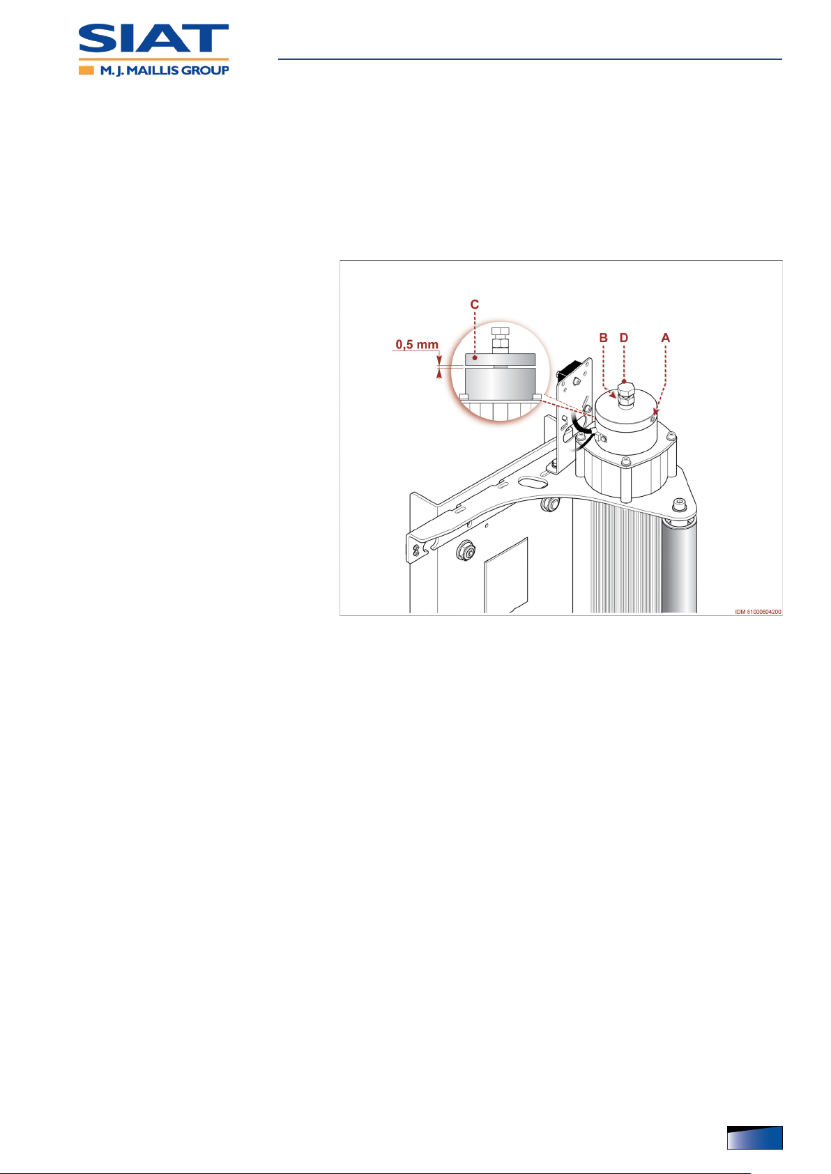
Reel holding carriages
Adjustment of brake
▀
– The operation must be carried out by the maintenance technician or by person-
nel with suitable competences, skills and knowledge.
– Make sure to full the required requirements in order to work under safe condi-
tions.
– This service should be carried out with the reel holding carriage lowered and the
machine safely at a stop.
1. Loosen the screw A.
2. Loosen the lock nut B.
3. Insert thickness gauge (thickness0,5
mm) under disc C.
4. Keep disc C in proper position and
regulate screw D to adjust brake.
– Clockwise: the distance gets higher.
– Counter clockwise: distance gets
shorter.
5. Tighten lock nut B.
6. Tighten the screw A.
– At the end of operations, check
that there are no tools or other
material near the moving parts or
in dangerous areas.
IDM 510-006-5
English languageOperation and maintenance manual
69

Reel holding carriages
Replacing the outer surface of roller
▀
– The operation must be carried out by the maintenance technician or by person-
nel with suitable competences, skills and knowledge.
– Make sure to full the required requirements in order to work under safe condi-
tions.
– This service should be carried out with the reel holding carriage lowered and the
machine safely at a stop.
1. Loosen the screws A.
2. Disassemble the brake assembly B.
3. Remove in a sequence the compo-
nents C-D-E.
4. Unscrew screw F.
5. Unscrew the nuts G.
6. Remove the plate H.
7. Extract spacer L.
8. Remove stop ring M.
9. Remove the component N.
10. Remove all the external cylinder sur-
face inserts P, one at a time.
11. Thoroughly clean the grooves of the
roller.
12. Insert in a sequence, one at a time,
all the new external cylinder surface
inserts.
13. Install component N.
14. Reinstall the retainer ring M.
15. Install the spacer L.
16. Fit back the plate H and x it with the
nuts G without tightening.
17. Insert screw F and tighten it.
18. Adjust the position of the plate H and
tighten the nuts G.
19. Install in a sequence the components E-D-C.
20. Install the brake assembly B and x it with the screws A.
– At the end of operations, check that there are no tools or other material near the
moving parts or in dangerous areas.
70
English language Operation and maintenance manual
IDM 510-006-5

Reel holding carriage (LP)
Main components
▀
A) Structure: it is equipped with wheels
for vertical shifting of carriage on column.
– In the structure a fall arrest system is
installed, which stops the carriage in
case of lifting belt failure.
B) Reel holder: it is equipped with
braking system to avoid reel unwinding.
C) Rollers: they are used to pre-stretch
the lm.
– The rollers are coupled with gears.
D) Roller (idle)
Reel holding carriages
– On closing the guard , the roller D is
positioned centrally with respect to
the rollers C.
E) Dancer roller (idle): it is equipped
with sensor to detect the lm tension.
– The roller is equipped with a sensor
that interfaces with the electric motor
G to adjust the speed of the rollers C.
F) Roller (idle)
G) Electric motor: it drives the pre-
stretch rollers.
H) Interlocked mobile guard: safety
device to prevent access to the components whose operation may represent a risk.
– When opening the guard, the machine stops in safe conditions. The machine restarts
only once the guard has been closed and operation has been restored.
L) Protective guard for the drive system of rollers
M) Photocell: it detects the presence and the height of the load to be wrapped in order to
stop the upward movement of reel holding carriage.
– On request, a “black” version of the photocell can be supplied, specically designed to
detect wrapped items or products with a prevalence of dark surfaces.
IDM 510-006-5
English languageOperation and maintenance manual
71

Film Coil Feeding
▀
1. Lower the reel holding carriage until
its endstroke.
2. Open the cover G.
3. Remove the cardboard core of the
reel.
4. Insert the new reel.
Check whether the wrapping lm has
the same chemical-physical properties as that installed in the reel holder
carriage.
If lm characteristics appear to be
different, consider whether you
should adjust the lm tension.
5. Insert lm according to the required
direction of the adhesive size.
Reel holding carriages
Important
In order to avoid transferring impurities to the surfaces of the guiding rollers, discard the outer wrapping lm layer on the reel.
6. Tie the trailing end of the lm to the base of the product to be wrapped.
7. Close the cover G.
8. Start wrapping.
Tension adjustment of lm
▀
– The operation is necessary to adjust the lm tension on the load to be wrapped.
1. Repeatedly press the button D until selecting the pa-
rameter Í.
– LED turns on.
2. Adjust the lm tension via the controls F.
72
English language Operation and maintenance manual
IDM 510-006-5

Reel holding carriages
Replacement of pre-stretch kit
▀
– The operation must be carried out by the maintenance technician or by person-
nel with suitable competences, skills and knowledge.
– Make sure to full the required requirements in order to work under safe condi-
tions.
– This service should be carried out with the reel holding carriage lowered and the
machine safely at a stop.
At delivery, machine pre-stretch corresponds to 240%.
To set pre-stretch to 200 %, replace the gears as indicated.
1. Disassemble the guard A.
2. Loosen screws B and move motor C
in order to completely loosen belt D.
3. Remove the belt D.
4. Loosen screw E and remove gear F.
5. Loosen nut G and loosen gear H.
IDM 510-006-5
English languageOperation and maintenance manual
73

6. Loosen screw L and remove gear M.
7. Loosen screw N and remove gear P.
8. Install new gear M and tighten screw
L.
9. Install new gear P and tighten screw
N.
10. Insert the pin of gear H into one of
the holes in order to combine it properly with gears M-P.
11. Lock gear in proper position by
means of nut G.
12. Install gear F again and tighten
screw E.
13. Install belt D.
14. Shift electric motor C and simultane-
ously tighten screws B to adjust the
tension of belt D.
Reel holding carriages
15. Reassemble the guard A.
– At the end of operations, check
that there are no tools or other
material near the moving parts or
in dangerous areas.
74
English language Operation and maintenance manual
IDM 510-006-5

Net-type reel holder carriage
Main components
▀
A) Structure: it is equipped with wheels
for vertical shifting of carriage on column.
– In the structure a fall arrest system is
installed, which stops the carriage in
case of lifting belt failure.
B) Reel holder: it is equipped with
braking system to avoid reel unwinding.
C) Roller: it tightens the net.
D) Roller (idle)
E) Ring: this device is used to adjust
the tightening of net.
Reel holding carriages
F) Lever: device used to disengage the
roller C.
G) Photocell: it detects the presence
and the height of the load to be
wrapped in order to stop the upward
movement of reel holding carriage.
– On request, a “black” version of the
photocell can be supplied, specically designed to detect wrapped items
or products with a prevalence of dark
surfaces.
H) Lever: control to be rotated to adjust
the braking degree.
– Clockwise: the value increases.
– Anti-clockwise: the value decreases.
IDM 510-006-5
English languageOperation and maintenance manual
75

Supplying the reel with net
▀
1. Lower the reel holding carriage until
its endstroke.
2. Lift the lever F to its vertical position.
3. Remove the cardboard core of the
reel.
4. Insert the new reel.
Check whether the wrapping lm has
the same chemical-physical properties as that installed in the reel holder
carriage.
If lm characteristics appear to be
different, consider whether you
should adjust the lm tension.
Important
In order to avoid transferring impurities to the surfaces of the guiding
rollers, discard the outer wrapping
lm layer on the reel.
Reel holding carriages
5. Tie the end of the net to the base of the product to be wrapped.
6. Start wrapping.
7. Lower the lever F to horizontal position after performing at least one wrap.
Adjustment of net tension
▀
– The operation is necessary to adjust the net tension on the load to be wrapped.
1. Lower the reel holding carriage until
its endstroke.
2. Lift the lever F to its vertical position.
3. Start wrapping.
4. Lower the lever F to horizontal posi-
tion after performing at least one
wrap.
5. Adjust the net tension by means of
ring E.
– Clockwise: the value increases.
– Anti-clockwise: the value decreas-
es.
76
English language Operation and maintenance manual
IDM 510-006-5

Reel holding carriages
Cleaning and replacement of brake disc
▀
– The operation must be carried out by the maintenance technician or by person-
nel with suitable competences, skills and knowledge.
– Make sure to full the required requirements in order to work under safe condi-
tions.
– This service should be carried out with the reel holding carriage lowered and the
machine safely at a stop.
1. Lift the lever A to its vertical position.
2. Remove the fastening elements and
remove the lever.
3. Remove in a sequence the components B-C-D-E.
4. Clean the contact surfaces of the
brake discs E-F.
5. Check the wear level of the friction
material of the disc E.
– In the case of excessive wear, re-
place the component.
6. Install the disc E with the friction ma-
terial facing downwards.
7. Install in a sequence the components D-C-B.
8. Engage the lever A in a vertical posi-
tion and insert the fastening elements.
9. Lower the lever to its horizontal position.
– At the end of operations, check
that there are no tools or other
material near the moving parts or
in dangerous areas.
IDM 510-006-5
English languageOperation and maintenance manual
77

Reel holding carriages
Replacement of the net tensioning roller
▀
– The operation must be carried out by the maintenance technician or by person-
nel with suitable competences, skills and knowledge.
– Make sure to full the required requirements in order to work under safe condi-
tions.
– This service should be carried out with the reel holding carriage lowered and the
machine safely at a stop.
1. Lift the lever A to its vertical position.
2. Remove the fastening elements and
remove the lever.
3. Remove in a sequence the components B-C-D.
4. Remove the component F.
5. Unscrew screw G.
6. Unscrew the nuts H.
7. Remove the plate L.
8. Remove stop ring M.
9. Disassemble the roller (P) and re-
place it.
10. Reinstall the retainer ring M.
11. Fit back the plate L and x it with the
nuts H without tightening.
12. Insert screw G and tighten it.
13. Adjust the position of the plate L and
tighten the nuts H.
14. Install component F.
15. Install in a sequence the compo-
nents D-C-B.
16. Engage the lever A in a vertical posi-
tion and insert the fastening elements.
17. Lower the lever to its horizontal position.
– At the end of operations, check
that there are no tools or other
material near the moving parts or
in dangerous areas.
78
English language Operation and maintenance manual
IDM 510-006-5

Analytical index
A
– Alarm message table, 54
– Attached documentation, 5
B
– Battery replacement, 60
C
– Charge of accumulator batteries, 51
– Control description, 28
– Cycle, 17
D
– Daily check of the safety bumper, 45
– Description of outer areas, 25
– Description of the main components, 14
– Description of the safety devices, 22
– Disassembly and reassembly of battery panel, 42
- Assembly of battery panel, 42
E
– Emergency stop and new start-up, 32
- Stop with activation of the emergency bumper, 32
- Stop with activation of the emergency button, 32
G
– general description of the machine, 13
– General safety warnings, 5
– Glossary of the terms, 4
H
– How to adjust the feeler, 56
I
– Incorrect uses that are reasonably expected, 20
M
– Machine Disposal and Scrapping, 61
– Maintenance of accumulator batteries (GEL), 50
– Manufacturer and machine identication, 16
– Monthly check of the safety bumper, 46
N
– Net-type reel holder carriage, 75
- Adjustment of net tension, 76
- Cleaning and replacement of brake disc, 77
- Main components, 75
- Replacement of the net tensioning roller, 78
- Supplying the reel with net, 76
O
– Optional Accessories, 21
P
– Position of information and safety plates, 26
– Problems, causes, remedies, 53
– Purpose of the manual, 3
IDM 510-032-5_Indice analitico
R
– Recipe lock/unlock mode, 41
- Recipe function “P0”, 41
– Recipe management, 39
- Loading a recipe, 40
- Modifying a recipe, 39
– Recommendations for accumulator batteries, 49
– Recommendations for maintenance interventions, 43
– Recommendations on Operation and Use, 27
– Reel holding carriage (FM), 66
- Adjustment of brake, 69
- Cleaning and replacement of brake disc, 68
- Film Coil Feeding, 67
- Main components, 66
- Replacing the outer surface of roller, 70
- Tension adjustment of lm, 67
– Reel holding carriage (LP), 71
- Film Coil Feeding, 72
- Main components, 71
- Replacement of pre-stretch kit, 73
- Tension adjustment of lm, 72
– Reel holding carriage (M), 62
- Cleaning and replacement of brake disc, 64
- Film Coil Feeding, 63
- Main components, 62
- Replacing the outer surface of roller, 65
- Tension adjustment of lm, 63
– Replacing the lifting belt of the carriage, 58
– Residual risks, 19
S
– Safety and information symbols, 11
– Safety Warnings for Handling and Installation, 6
– Safety Warnings for Maintenance and Adjustments, 9
– Safety Warnings for Operation and Use, 7
- Safety Manager Obligations, 7
– Safety warnings for the electrical equipment, 10
– Safety warnings for the environmental impact, 10
– Safety Warnings on Misuse, 8
– Safety Warnings on Residual Risks, 8
– Scheduled maintenance intervals, 44
– Sensitivity adjustment for the product to be wrapped
detection photocell, 57
– Setup of parameter values, 38
– (Single or double) automatic wrapping, 33
- Normal stop, 34
– (Single or double) automatic wrapping with sheet
feeder, 35
- Normal stop, 37
– Specications, 23
T
– Types of wrapping, 18
Y
– Yearly check of the safety bumper, 48
English languageOperation and maintenance manual
79

 Loading...