

Page 1
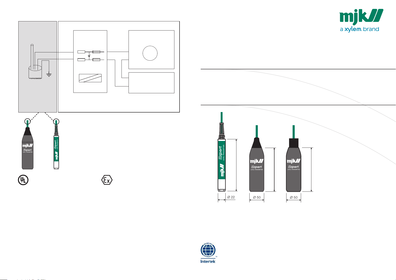
135 mm
135 mm
164mm
Control Drawing 5222
Hazardous Area Non-Hazardous Area
Class I Division 1 Group A-D
Zone 1 or 2
Gas groups IIA, IIB or IIC
Ventilating tube
Wire (1) Red
Wire (2) Brown
Shield
Wire (3)
Black
Zener barrier
+
-
or EX isolator
+
-
-
+
Power supply
+
-
Apparatus
EN 2.76/2.77 Expert 1400/3400 2007
MANUAL
Expert™ 1400 / Expert™ 3400
Submersible Hydrostatic Level Transmitters
Ventilating tube
shall be terminated
before exiting the
hazardous area !
Model 3400 Model 1400
Class I, Division 1, Group A-D T4/T5/T6
Applicable Ex-standards:
UL 913, 8th Ed., Rev. 2013
UL 60079-0, 6th Ed. Rev. 2013 (as referenced by UL 913)
UL 60079-11, 6th Ed., Rev. 2013 (as referenced by UL 913)
The user shall check the compatibility bet ween the
process media and the materials of the apparatus.
Ratings:
Vmax(Ui) = 30Vdc
Imax(Ii) = 0.101 A
Pmax(Pi) = 0.75 W
C i 3.5 nF + C cable
L i 7 µH + L cable
MJK CABLE:
C Cable : 0,8 nF / m
L Cable : 1,5 µH / m
Conform to IEC 60079-11 6.3.13
CENELEC EN 60079-0:2012+A11:2013
CENELEC EN 60079-11:2012
IEC 60079-0 Ed. 6
IEC 60079-11 Ed. 6
II 2G Ex ia IIC T6 (-20°C≤Ta≤40°C)
II 2G Ex ia IIC T5 (-20°C≤Ta≤50°C)
II 2G Ex ia IIC T4 (-20°C≤Ta≤80°C)
Specific conditions for use
• Before taking into use, the user shall make an evaluation of the compatibility between proces s media
and the materials in the 1400 or 3400 Expert
• The equipment must be connected via an approved or cer tified inter face/zener barrier placed out
side the hazardous area.
• For ins tallations in which both the Ci and Li of the connected apparatus exceeds 1% of the Co and Lo
parameters (excluding the cable), then 50% of Co and Lo parameters are applicable and shall not be
exceeded.
• For model 3400 Expert
possibility of electrostatic discharge.
The maximum length of the cable is c alculated from the Expert pressure transmitters internal capacity
(3,5 nF) and internal self-induction (7 μH). The cable capacity (MJK 0,8nF/m) and the self-induction (MJK
1.5 μH/m) is added.
The 2 values are added to calculate the total capacit y and the total self-induction. The Ex isolator or
Zener barrier is marked with the maximum capacity and self-induction for the connection. These two
values must never be exceeded.
TM
Level Transmit ter: Warning - Clean only with a damp cloth to prevent the
TM
Level Transmitter.
Demko 06 ATEX 137949X
CE Certificate of conformity
This product complies with the requirements concerning electromagnetic compatibility (EMC) stipulated in Council
direc tive no. 89/336/EEC, 2004/108/EC, 1999/EC, on the approximation of the laws of the Member States relating
to electromagnetic compatibility.
We declare that the product complies to the values stipulated in EN 61000- 6- 4 2007-02-19, EN 61000-6-2 2005-09-08,
EN 600079-0 : 2012, EN 60079-11 : 2012.
Connect, Mµ Connect, Chatter, MagFlux, Oxix, pHix compact, Shuttle and SuSix are registered trademarks of MJK Automation ApS.
Find Quality Products Online at: [email protected]
www.GlobalTestSupply.com
As our products are developed continuously, we reserve the right to make any alterations without prior notice © 2015 Xylem, Inc.
Page 2
Introduction
Thank you for choosing ExpertTM Level Transmitter.
We have done everything possible to make an
ExpertTM Level Transmit ter that can fulfil all your
demands.
ExpertTM Level Transmit ter is suitable for all kinds
of level measurements. It can control and supervise
levels i n wells and tanks - including aggressive and
polluted me dia.
The ExpertTM Level Transmit ter is both easy to install and put into service, but read this manual first
- then you will benefit the most from the E xpertTM
Level Transmitter right from the beginning.
You can always cont act your representative or the
MJK Ser vice Hotline for advice and guidance. Also,
take a look at ht tp://www.mjk.com.
ExpertTM Level Transmitter is registered trademark of
MJK.
On the model Exper t
the pressure ranges together with the corre sponding par t numbers are laser engraved on the
transmitter housing.
Expert
On the model Exper t
the pressure ranges together with the corre sponding par t numbers are laser engraved on the
transmitter housing.
TM
1400 Level Transmit ters,
TM
1400 Level Transmitter
TM
3400 Level Transmitters,
Safety instructions
1: Read this manual carefully.
2: Be aware of the environment on the installation
site. Wear necessary protective equipment and follow
all current safety regulations.
3: Do not operate the equipment outside the specified electrical, thermal and mechanical parameters
(see datasheet). Ins tall the device only in media for
which the wet ted materials have sufficient durability. (See datasheet for housing material.)
Max. supply voltage is 30 VDC.
4: Do not connec t or use any programming interface/equipment while the ExpertTM Level Transmitter
is located in an explosion hazardous environment.
Hazardous areas
1: All current local and national standards, regula-
tions regarding installation and use of Ex or hazardous zone approved equipment, certifications and
safety instructions for Ex equipment that have been
used together with the installation of the E xper tTM
1400 and 3400 Level Transmitter must be strictly
observed.
2: The use of an approved zener barrier or isolator
is mandatory when installing Expert™ 1400 and
3400 Level Transmitter in explosion hazardous
areas.
Repair
1: Repair of Ex approved equipment must only be
done by MJK or by a service representative approved by MJK.
Mechanical mounting
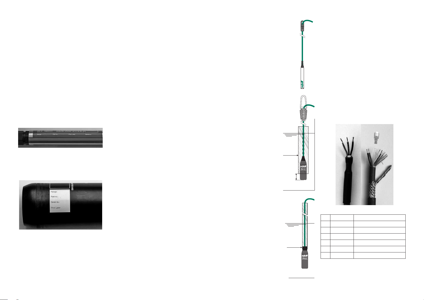
ExpertTM Level Transmitter model 1400
1: Mount a suitable hook over the desired
measuring location. Note the weight of the
cable.
2: Lower the ExpertTM Level Transmitter
into the liquid.
ExpertTM Level Transmitter model 3400
1: Mount a suitable hook over the desired
measuring location. Note the weight of the
cable.
2: Lower the ExpertTM Level
Transmitter into the liquid.
3: If the ExpertTM Level
Transmitter is to be used in
a wetwell or other locations
with turbulence or other
disturbance, it is advisable to install a pipe (min.
nominal diameter = 75 mm)
to protect the ExpertTM Level
Transmitter from bumping
into the wall or other components.
Take care not to hit the
bottom hard since it may
damage the Exper tTM Level
Transmitter!
It is ver y important that minimum 25 mm of the ExpertTM
Level Transmitter is not
covered by the pipe!
Cable
bracket
Protective pipe
Protec tive pipe.
Min. nominal
diameter = 75mm
Min. 25- 50 mm
Model 3400
Cable
bracket
Model
140 0
Electrical mounting
Cable length vs. supply voltage
The cable can be leng thened with any type of
cable1). Although the measuring signal is not sensitive to electric al noise, we recommend the use of a
screened cable.
Ensure that no moisture can enter the pressure
compensation tube inside the cable.
Designation of wires, cutting & stripping the cable
The factory delivered cable has the wires marked
with the numbers 1 - 2 - 3. If the cable needs to
be cut ted and stripped, the shield should be connected as the no. 3 wire.
Do NOT connect any of the colored programming wires as it may damage the transmitter. The
programming wires should be cut of f in different
lengths to prevent them from short circuit2).
Take care not to block or squeeze the air pressure
compensation tube.
➃
➁
➂
➀
➄
➀
➁
➅
➃
TM
Expert
3400 Level Transmitter
ExpertTM Level Transmitter
model 3400 with thread top
1: Mount the ExpertTM Level
Transmitter onto a 1” pipe and
mount the pipe firmly at the
desired measuring location.
2: Lower the ExpertTM Level
Transmitter into the liquid.
Take care not to hit the bottom hard as it
may damage the ExpertTM Level Transmitter!
2 3
Find Quality Products Online at: [email protected]
www.GlobalTestSupply.com
ISO thread 1”
Model 3400
Factory delivery
No. Wire Color Description
1 Red or White + 10-30 V DC
2 Brown 4-20 mA (-supply)
3 Black P/E Connection (Ground)
4 Moisture filter
5 Transparent Air pressure compensation tube
6 Programming wires
1) If the cable i s extended, t he complete cap acity and sel f-inducti on
cannot e xceed the maxi mum specifica tions. For UL or E x approved
mounti ng, see control dr awing on the nex t page.
2) Do not conn ect a program ming unit to the E xpertTM Level Transmitter
or make any at tempt to prog ram the Exper tTM Level Transmitte r while it is
locat ed in an explosion h azardous zone !
Cutted and s tripped
 Loading...