

Mizerak P5423W2 User Manual

W e striv e t o ensur e tha t ou r product s ar e o f th e highes t quality
an d fre e o f manufacturin g defect s o r missin g parts . Howev e r , if
yo u hav e an y problem s wit h you r ne w product,
D O NO T RETUR N I T T O TH E S T ORE ,
pleas e contac t u s tol l fre e @:
1-86 6 -556-2757
F AX : 1-866-873-3531
pooltables@escaladesports.com
O r writ e to:
Escal a d e Spor t s
Cust o me r Servi c e Depa r tme n t
P .O . Bo x 8 8 9
Evansvill e I N 47706
Please
Whe n contactin g Escalad e Sport s pleas e provid e you r mode l numbe r , d at e
cod e (i f a pplicable ) an d par t n umbe r i f requestin g a replacemen t part . T hes e
number s ar e locate d o n th e product , packaging , an d t hi s owner s m anual .
Y ou r Mode l Numbe r _____ _ ________ _ ______
Dat e Cod e ________________________
hav e you r mode l numbe r whe n inquirin g abou t parts.
P5423W
2-P5423W- -WJ
Purchase Date ________________________
PLEASE RETAIN THIS INSTRUCTION MANUAL FOR FUTURE REFERENCE
All Rights Reserved.
©
201 2 Escalad e Sports
1
Fo r Custome r Servic e Cal l 1-866-556-2757
CAUTION
THE SPRAY ADHESIVE USED FOR APPLYING PLAYFIELD CLOTH IS EXTREMELY FLAMMABLE AND UNDER
PRESSURE
CHILDREN
AREA MUST BE WELL VENTILATED
To ensure safety, do not attempt to assemble system without followinginstructions carefully. Proper and complete assembly, use, and supervision is essential for
proper operation and to reduce the risk of accident or injury.Ahigh probability of serious injury exists if this system is not installed, maintained, and
operated properly.
! CAREFULLY READ CAUTIONS ON SPRAY ADHESIVE CONTAINER ! KEEP OUT OF THE REACH OF
! DO NOT USE OR STORE NEAR HEAT SOURCE , FLAMES , SPARKS OR WHEN SMOKING !
. OPEN DOORS AND WINDOWS WHEN USING SPRAY ADHESIVE .
WORK
READ AND FOLLOW ALL ASSEMBLY, OPERATION, AND
SAFETY INSTRUCTIONS CAREFULLY. AT LEAST TWO
ADULTS ARE NEEDED TO PUT THIS TABLE
TOGETHER.
Tools Needed: (Not Included)
Philips Screwdriver
•
• Putty Knife
• Needle Nose Plyers
• Tape Measure
• Sanding Block
• Scissors or Sharp Knife
• Adjustable Wrench
• Small Hammer
• Carpenters Level
• Ratchet with socket
• 12mm Socket or End Wrench
NOTE: This table adds weight to any floor. Be sure floor can withstand this kind of weight.
If floor sags, table will be impossible to level.
All Rights Reserved.
©
2012 Escalade Sports
2
For Customer Service Call 1-866-556-2757
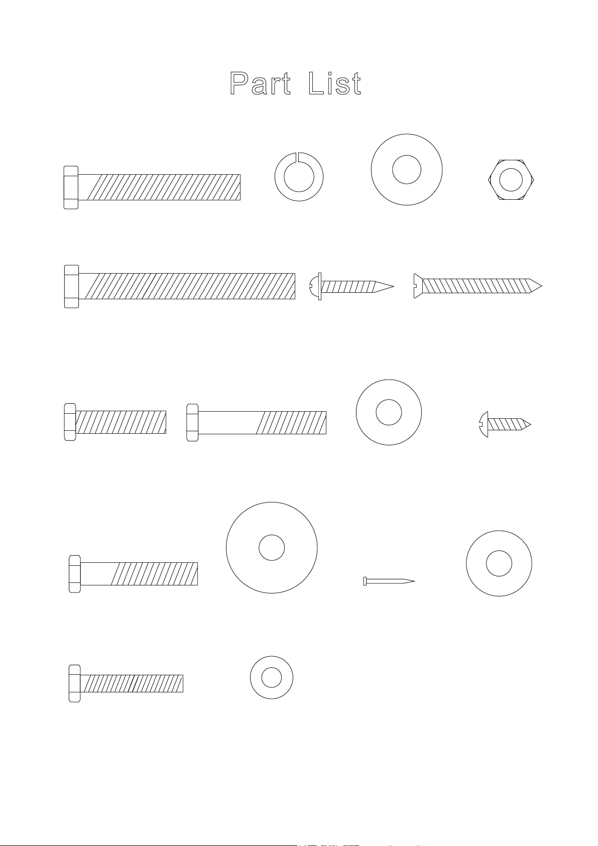
Pa r t Li s t
(To Scale)
H1 - 3/8” x 2-1/4” Bolt
(8 pcs)
H5 - 3/8” x 3” Bolt
H8 - 5/16” x 1-1/4” Bolt
(8 pcs)
(8 pcs)
H2 - 3/8” Lock
Washer (16 pcs)
H9 - 5/16” x 1-3/4” Bolt
(12 pcs)
H3 - 3/8” x 25mm
Flat Washer (32 pcs)
H6 - WP/4 x 1”
Phillips Washer
Head Screw
(12 pcs)
H10 - 5/16” x 23mm
Flat Washer (12 pcs)
H4 - 3/8” Hex Nut
(16 pcs)
H7 - F5 x 1-3/4”
Phillips Flat Head Screw
(16 pcs)
H11 - T4 x 15mm
Phillips Round Head
Screw (24 pcs)
H12 - 5/16” x 1-5/8” Bolt
(18 pcs)
H16 - 1/4” x 1-1/2” Bolt
(4 pcs)
All Rights Reserved.
©
201 2 Escalad e Sports
H13 - 5/16” x 32mm
Flat Washer (18 pcs)
H17 - 1/4” x 15mm
Flat Washer (4 pcs)
3
H14 - Pocket Nail
(36 pcs)
Fo r Custome r Servic e Cal l 1-866-556-2757
H15 - 5/16” x 23mm
Flat Washer
(8 pcs)
A1
A2
A3
A4
Cu e Stic k
A5
Billiar d Bal l
T1
Playfield Grout Kit
2 Pcs
1 Se t
1 Pc
T riangl e
1 P c
A6
Cue Chalk
2 Pc s
T2
Playfield Cloth to Playfield
- Spray Adhesive 1 P c
Playfield Cloth Brush
1 P c
T3
Sand Paper for Dried Grout
1 Pc
Playfield Cloth
1 P c
T4
Wrench
1 Set
P1
P5
P9
Leg
2 Pcs
End Board
2 Pcs
P2
Main Metal Beam
2 Pcs
P6 - Slatron
P6S - Slate
End Play Bed
2 Pcs
P10
P3A
NOTE: For P5
Installation.
P3B
NOTE: For P16
Installation.
End Slat
2 Pcs
P7 - Slatron
P7S - Slate
Middle Play Bed
1 Pc
P11
P4
Middle Slat
2 Pcs
P8
Shim
8 Pcs
Can also use playing cards (not included)
or Slate / Slatron Shims
P12
Side Top Rail
2 Pcs
All Rights Reserved.
©
201 2 Escalad e Sports
End Top Rail
2 Pcs
Corner Cap
4 Pcs
4
Fo r Custome r Servic e Cal l 1-866-556-2757
Side Apron
2 Pcs
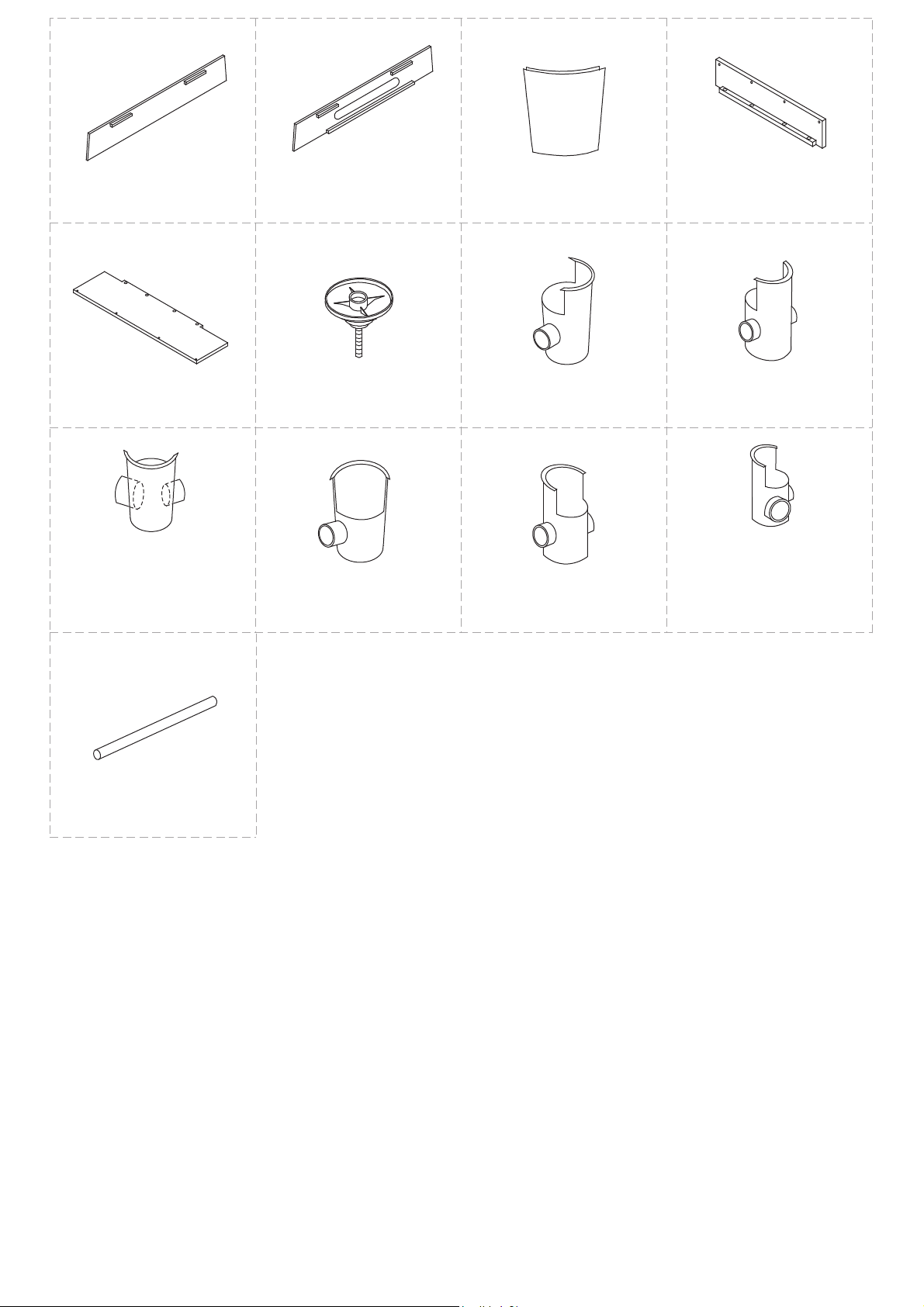
P13
P14
P15
P16
End Apron
1 Pc
P17
Ball Return Tray Board
1 Pc
P21
Right Corner Pocket
NOTE: Attach this pocket on
same end as P14 Apron with
Ball Return Opening
1 Pc
End Apron with Ball
Return Opening
1 P c
P18
Leg Leveler
4 Pcs
P22
Left Corner Pocket
1 Pc
Corner Post
4 Pcs
P19
Right Corner Pocket
1 Pc
P23
Left Middle Pocket
1 Pc
Ball Return
Support Board
1 Pc
P20
Right Middle Pocket
1 Pc
P24
Left Corner Pocket
NOTE: Attach this pocket on
same end as P14 Apron with
Ball Return Opening
1 Pc
P25
Ball Return Tube
4 Pcs
All Rights Reserved.
©
201 2 Escalad e Sports
5
Fo r Custome r Servic e Cal l 1-866-556-2757
P ARTS REQUIRED:
2 pcs - P1 Leg
4 pcs - P18 Leg Leveler
ST E P 1 :
Thread P18 Leg Levelers into P1 Leg as shown in Figure 1. .
P18
Note: Remove Parts Box, Leg Levelers,
Plastic Pockets and Spray Glue from
inside both Legs.
P18
Figure 1
All Rights Reserved.
©
201 2 Escalad e Sports
P1
6
Fo r Custome r Servic e Cal l 1-866-556-2757
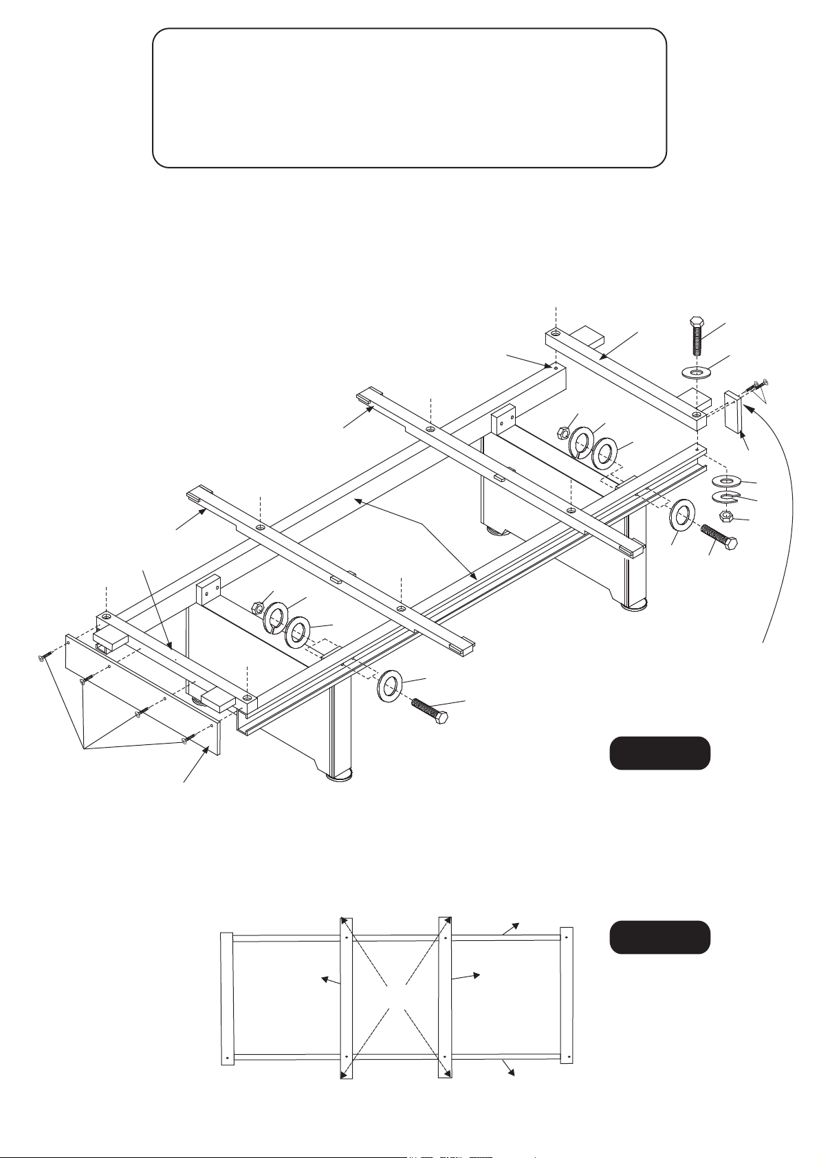
PARTS REQUIRED:
8 pcs - H1 Bolt
16 pcs - H2 Lock Washer
32 pcs - H3 Washer
16 pcs - H4 Hex Nut
8 pcs - H5 Bolt
8 pcs - H6 Screw
2 pcs - P2 Main Metal Beam
2 pcs 2 pcs - P4 Middle Slat
2 pcs - P5 End Board
1 pc 1 set - T4 Wrench
P3A & P3B End Slat
P16 Ball Return Support Board
ST E P 2 :
Attach each P2 Main Metal Beam to P1 Leg assembly as shown Figure 2 using H1 Bolts, H3 Washers,
H2 Lock Washers and H4 Hex Nuts. Use the T4 Wrench to assemble the hardware. Do not tighten
hardware at this time. Place P3 A and P3B End Slats and P4 Middle Slats across P2 Main Beams and
attach using H5 Bolts, H3 washers, H2 Lock Washers and H4 Hex Nuts as shown in Figure 2.
Attach P5 End Boards to P3A End Slat using pre-drilled pilot holes with H6 Screws as shown in Figure 2.
Attach P16 Ball Return Support Board to P3B End Slat using pre-drilled pilot holes with H6 Screws as
shown in Figure 2.
IMPORTANT NOTE:
Make sure holes are located on the
top of both P2 Main Metal Beams.
P3A
H5
H3
H6
P3B
P4
P16
H4
H2
P4
H3
P2
H3
H1
H4
H2
H3
H3
H1
Note: P5 End Boards must be
flush or slightly lower than top
of P3A End Slats.
Figure 2
H6
P5
H3
H2
H4
STEP 3:
Square up P4 Slats by measuring diagonally as show in Figure 3. Diagonal measurements should be
the same within 1/8". If the frame is not square, adjustment can be made by moving table beams P2 in
opposite directions. Once the frame is square, tighten all hardware.
P2
Figure 3
P4
P2
Fo r Custome r Servic e Cal l 1-866-556-2757
All Rights Reserved.
©
201 2 Escalad e Sports
P4
SAME
DIMENSION
7
 Loading...