

Miyachi Unitek 250DPS, 250DP, 250DP/230, 250DP/208, 250DPS/100 User Manual
...
USER'S MANUAL 990-280
Revision H March 2004
250DP DUAL PULSE
STORED ENERGY RESISTANCE WELDING
POWER SUPPLIES
Model Stock No.
250DP 1-250-XX
250DP/208 1-250-XX-01
250DP/230 1-250-XX-02
250DP/100 1-250-XX-03
250DPS 1-254-XX
250DPS/208 1-254-XX-01
250DPS/230 1-254-XX-02
250DPS/100 1-254-XX-03
NOTE: Units with the built-in Weld Sentry
Option also require User's Manual No. 990-291.

Copyright © 1998, 2002, 2004 Miyachi Unitek Corporation
The engineering designs, drawings and data contained herein are the proprietary work of
MIYACHI UNITEK CORPORATION and may not be reproduced, copied, exhibited or
otherwise used without the written authorization of MIYACHI UNITEK CORPORATION.
Printed in the United States of America.
Revision Record
Revision EO Date Basis of Revision
A ENRG-RLSE 1/94
B 17215 11/97
C 17405 4/98
D 17574 6/98
E 18282 5/00
F 18577 11/00
G 19146 01/02
H 20002 3/04
Released Original Manual.
Ɣ Reorganize data and update format.
Ɣ Incorporate Addendum 995-280, Rev A
(10/97); and Errata 996-280, Rev B.
Add operating features.
Correct Test Point designation.
Ɣ Add CAUTION statement about polarity in
chained weld schedules.
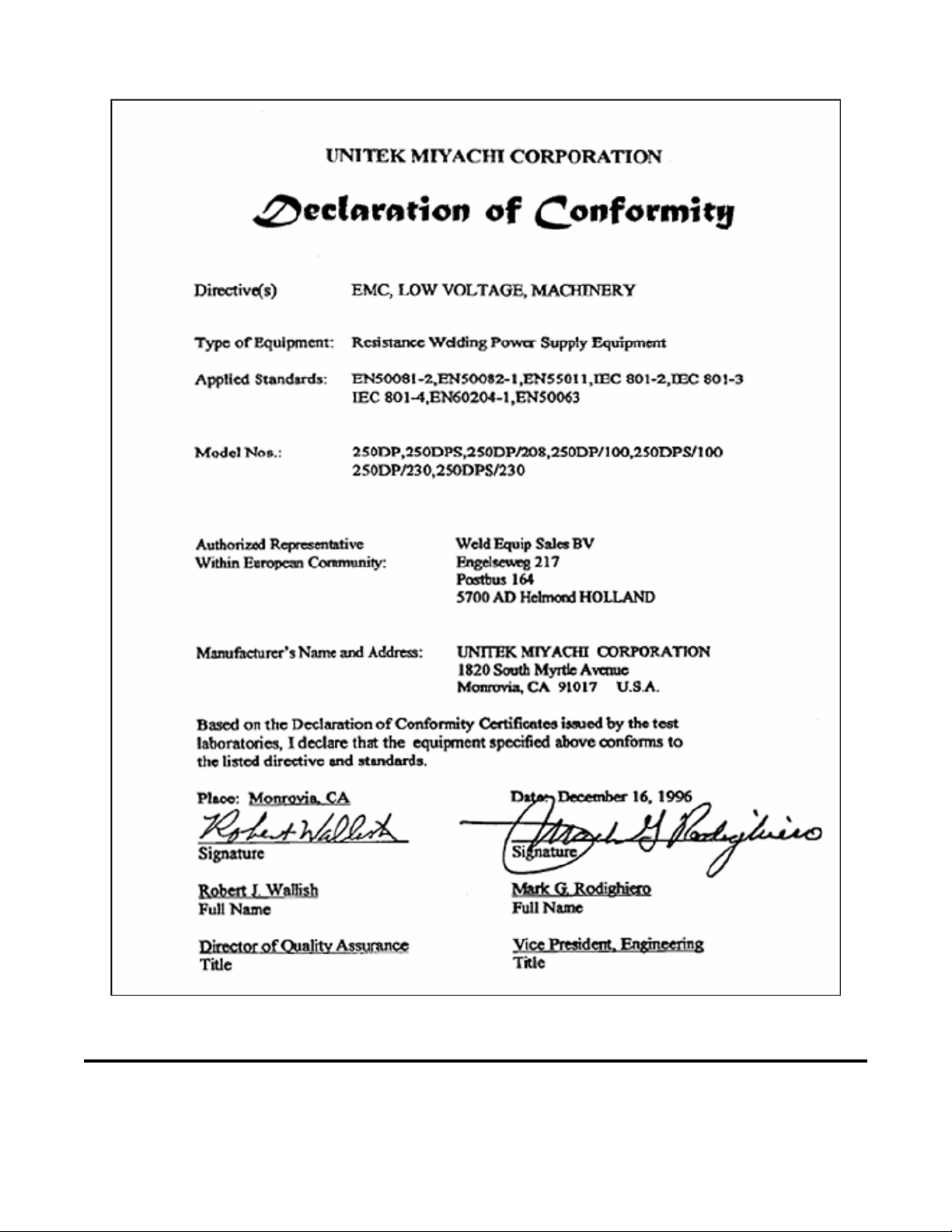
Ɣ Add Declaration of Conformity.
Ɣ Add tolerance to pulse output voltage.
Ɣ Clarify operation of relay outputs.
Complete Update
Updated Schematics. Minor formatting changes.
MODEL 250DP DUAL PULSE
RESISTANCE WELDING POWER SUPPLY
ii 990-280

CONTENTS
Revision Record ......................................................................................................................................... ii
Contents .................................................................................................................................................... iii
Contact Us ................................................................................................................................................. ix
Safety Notes ................................................................................................................................................x
Declaration of Conformity ........................................................................................................................ xi
CHAPTER 1: SYSTEM DESCRIPTION ....................................................................................... 1-1
Applications .................................................................................................................................... 1-1
Features ....................................................................................................................................... 1-2
CHAPTER 2: INSTALLATION ...................................................................................................... 2-1
Location ....................................................................................................................................... 2-1
Power Line...................................................................................................................................... 2-1
Welding Cables............................................................................................................................... 2-1
Rear Panel Components.................................................................................................................. 2-3
Firing Switch Connections.............................................................................................................. 2-4
Mechanical Firing Switch......................................................................................................... 2-4
Optical Firing Switch................................................................................................................ 2-4
3 Wire Firing Switches ............................................................................................................. 2-4
Air Actuated Weld Head Connections............................................................................................ 2-5
Air Valve Driver ....................................................................................................................... 2-6
Non Miyachi Unitek Air Actuated Weld Heads ....................................................................... 2-7
Air Actuated Weld Heads without Force Firing Switches........................................................ 2-7
Second Air Head....................................................................................................................... 2-7
Footswitch ....................................................................................................................................... 2-7
1-Level Footswitch ................................................................................................................... 2-7
2-Level Footswitch ................................................................................................................... 2-8
Remote Schedule Selection............................................................................................................. 2-8
Relay Outputs.................................................................................................................................. 2-8
Interconnection Diagram ................................................................................................................ 2-9
CHAPTER 3: OPERATING CONTROLS AND SCREENS........................................................ 3-1
Operating Controls.......................................................................................................................... 3-1
Screen Formats................................................................................................................................ 3-3
MODEL 250DP DUAL PULSE
RESISTANCE WELDING POWER SUPPLY
990-280 iii

CHAPTER 4: GETTING STARTED .............................................................................................. 4-1
Powering Up ................................................................................................................................... 4-1
Adjusting an Air Actuated Weld Head ........................................................................................... 4-1
CHAPTER 5: OPERATING INSTRUCTIONS ............................................................................. 5-1
Successful Welding......................................................................................................................... 5-1
Resistance Welding Parameters...................................................................................................... 5-1
Weld Schedule Development.......................................................................................................... 5-1
Weld Head Parameters.............................................................................................................. 5-2
250DP Power Supply Parameters ............................................................................................. 5-4
Making a Weld................................................................................................................................ 5-4
Evaluating the Weld........................................................................................................................ 5-4
Weak Weld................................................................................................................................ 5-5
Electrode Sticking..................................................................................................................... 5-5
Causes of Imperfect Welds ............................................................................................................. 5-5
Electrode Force and %Energy .................................................................................................. 5-5
Polarity...................................................................................................................................... 5-6
Weld Strength Profiles.................................................................................................................... 5-7
Destructive Testing ......................................................................................................................... 5-7
Electrode Maintenance.................................................................................................................... 5-8
CHAPTER 6: PROCESS DEFINITIONS AND WELD FUNCTIONS ....................................... 6-1
250DP States................................................................................................................................... 6-1
RUN State ................................................................................................................................. 6-1
STANDBY State....................................................................................................................... 6-2
PROGRAM State...................................................................................................................... 6-2
MENU State.............................................................................................................................. 6-3
HELP State................................................................................................................................ 6-4
NO WELD State ....................................................................................................................... 6-4
FIRE State................................................................................................................................. 6-4
Weld Function Field ....................................................................................................................... 6-4
Basic Function .......................................................................................................................... 6-5
Repeat Function ........................................................................................................................ 6-6
Rollspot Function...................................................................................................................... 6-7
CHAPTER 7: MAINTENANCE ...................................................................................................... 7-1
Modification and Calibration.......................................................................................................... 7-1
Cover Removal ......................................................................................................................... 7-1
Capacitor Bank Modifications .................................................................................................. 7-1
MODEL 250DP DUAL PULSE
RESISTANCE WELDING POWER SUPPLY
iv 990-280

Line Voltage Changes ................................................................................................................. 7-2
Calibration ................................................................................................................................... 7-8
Troubleshooting .............................................................................................................................. 7-10
Repair Service ................................................................................................................................. 7-11
Telephone Service ..................................................................................................................... 7-11
Factory Service Repair .............................................................................................................. 7-11
APPENDIX A: TECHNICAL SPECIFICATIONS .......................................................................A-1
250DP Power Supply .....................................................................................................................A-1
Power Requirements ......................................................................................................................A-1
Capacitor Bank ...............................................................................................................................A-1
Output Pulse Characteristics ....................................................................................................A-1
Weld Fire Lockout ...................................................................................................................A-2
Line Voltage Regulation ..........................................................................................................A-2
Turndown Circuit .....................................................................................................................A-2
Line Failure Turndown ............................................................................................................A-2
Over-Voltage Lockout .............................................................................................................A-3
Charge Lockout Circuit ............................................................................................................A-3
Polarity Selection ...........................................................................................................................A-3
Welding Speed ...............................................................................................................................A-3
Weld Schedules ..............................................................................................................................A-6
Weld Schedule Definition ........................................................................................................A-6
Options .......................................................................................................................................A-6
Schedule Number at Power-Up ...............................................................................................A-7
Utilities ......................................................................................................................................A-7
Information ....................................................................................................................................A-7
Weld Sentry ...................................................................................................................................A-7
System Set-up ................................................................................................................................A-8
Weld Functions ..............................................................................................................................A-8
Head Type ......................................................................................................................................A-8
Squeeze Line ............................................................................................................................A-8
Cool Time ................................................................................................................................A-9
Hold Time ................................................................................................................................A-9
Footswitch Type .............................................................................................................................A-9
FOOTSWITCH Connector ......................................................................................................A-9
Footswitch Weld Abort Feature .....................................................................................................A-10
Footswitch Weld Abort On ......................................................................................................A-10
Footswitch Weld Abort Off .....................................................................................................A-10
Firing Switch Type ........................................................................................................................A-10
Firing Circuit ............................................................................................................................A-10
Switch Debounce Time ............................................................................................................A-11
Mechanical Firing Switch Cable ..............................................................................................A-11
MODEL 250DP DUAL PULSE
RESISTANCE WELDING POWER SUPPLY
990-280 v

Optical Firing Switch Connector .............................................................................................A-11
Initiation Switch .............................................................................................................................A-12
Manual Head Operation ...........................................................................................................A-12
Air Head Operation ..................................................................................................................A-12
Chain Schedules Feature ................................................................................................................A-12
Step Count ................................................................................................................................A-12
Next Schedule ..........................................................................................................................A-13
Audible Buzzer ..............................................................................................................................A-13
End of Cycle Buzzer ON/OFF .................................................................................................A-13
Key Click .................................................................................................................................A-13
Weld Counter .................................................................................................................................A-14
Alarms ......................................................................................................................................A-14
Air Valve Driver ............................................................................................................................A-14
Air Valve Driver 1 ...................................................................................................................A-14
Air Valve Driver 2 ...................................................................................................................A-15
Air Valve Driver Receptacles ..................................................................................................A-15
Control Signals Connector .............................................................................................................A-15
Emergency Stop .......................................................................................................................A-16
Charge (Process) Inhibit ..........................................................................................................A-17
Remote Weld Schedule Selection ............................................................................................A-17
Binary Schedule Selection Code ..............................................................................................A-18
Relay Outputs .................................................................................................................................A-19
Accessory Port ...............................................................................................................................A-20
Input/Output Cable Connectors and Fusing ...................................................................................A-20
Input Line Power ......................................................................................................................A-20
Circuit Breakers .......................................................................................................................A-20
Fuses ......................................................................................................................................A-20
Power Input Connector ............................................................................................................A-20
Front Panel Switches ......................................................................................................................A-21
Microprocessor CPU ......................................................................................................................A-21
Display .......................................................................................................................................A-21
Cooling .......................................................................................................................................A-21
Physical Characteristics .................................................................................................................A-22
Index ................................................................................................................................................ Index-1
MODEL 250DP DUAL PULSE
RESISTANCE WELDING POWER SUPPLY
vi 990-280

ILLUSTRATIONS
Figure Title Page
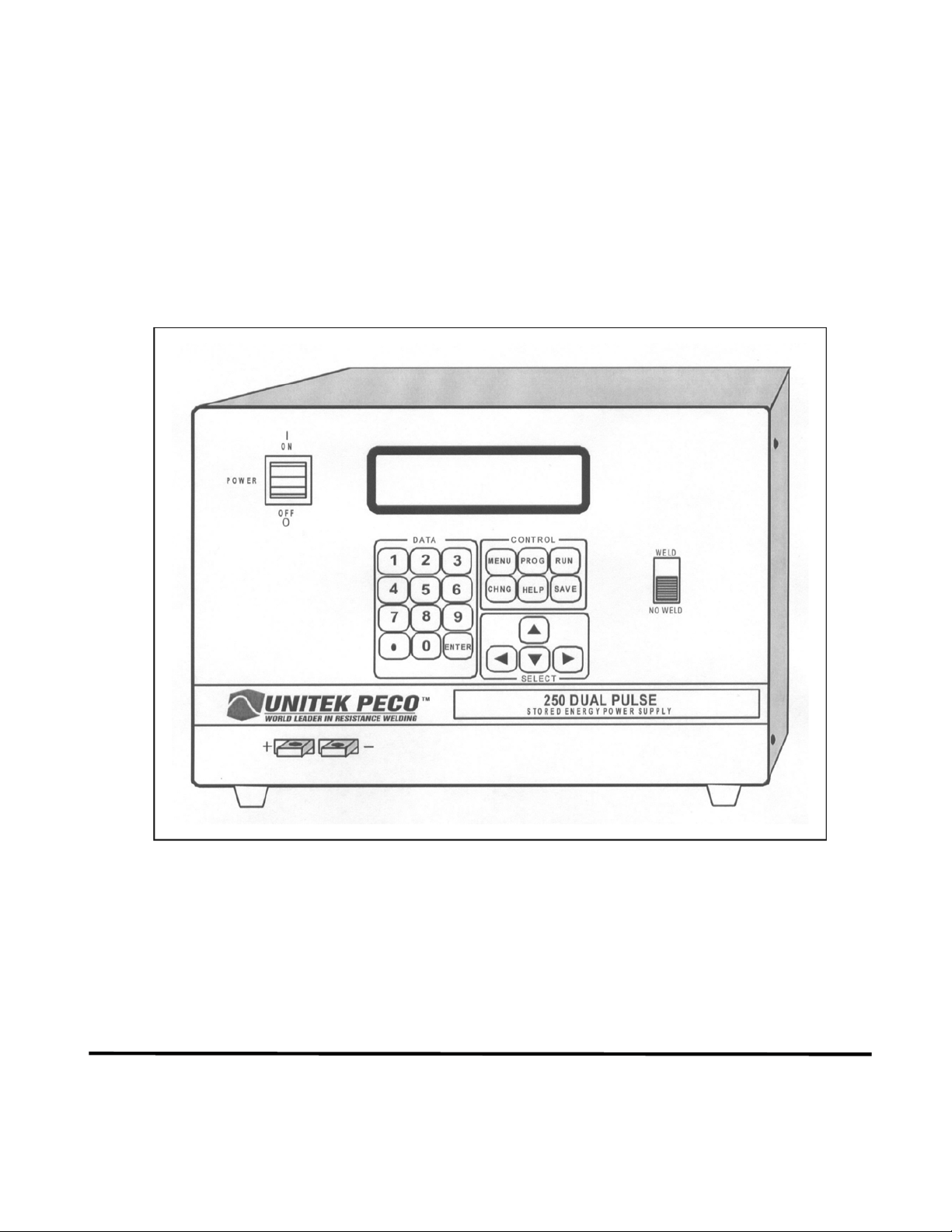
1-1 250DP Dual Pulse Resistance Welding Power Supply ............................................................... 1-1
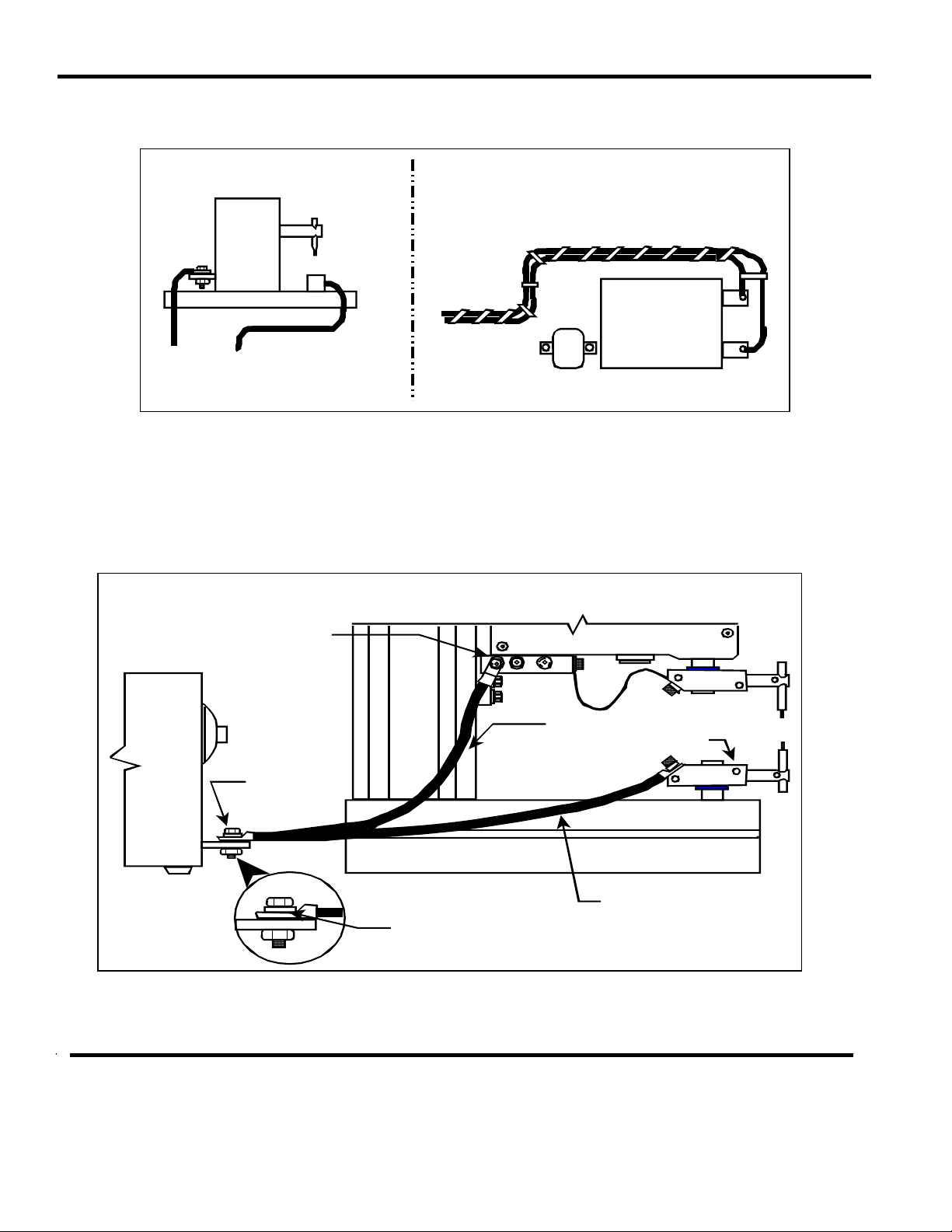
2-1 Cable Routing Examples .......................................................................................... 2-2
2-2 Terminal Connection Examples .......................................................................................... 2-2
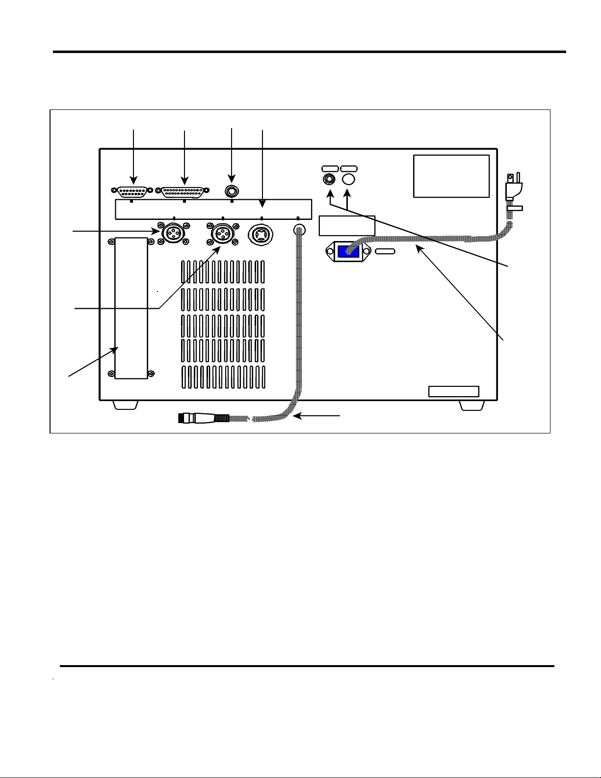
2-3 Rear Panel Components .......................................................................................... 2-3
2-4 Typical Solenoid Air Valve Assembly with a Single egulator ................................................... 2-6
2-5 250DP Equipment Interconnection Diagram .............................................................................. 2-9
3-1 Front Panel Controls .......................................................................................... 3-1
3-2 Screen Flow Chart .......................................................................................... 3-5
4-1 Typical Solenoid Air Valve System with Dual Regulators ........................................................ 4-2
4-2 Typical Solenoid Air Valve System with a Single Regulator ..................................................... 4-3
4-3 Measuring Preset Firing Force of the Weld Head with a Force Gauge ...................................... 4-4
4-4 Results of Excessive Air Pressure ..........................................................................................4-5
4-5 Weld Head Configuration Jumper Selection .............................................................................. 4-6
5-1 Effects of Excessive or Insufficient Heat, Time and Pressure .................................................... 5-2
5-2 Typical Weld Strength Profile .......................................................................................... 5-7
7-1 Line Voltage and Capacitor Bank Jumpering ............................................................................. 7-2
7-2 100 VAC Line Voltage Configuration ........................................................................................ 7-4
7-3 115 VAC Line Voltage Configuration ........................................................................................ 7-5
7-4 208 VAC Line Voltage Configuration ........................................................................................ 7-6
7-5 230 VAC Line Voltage Configuration ........................................................................................ 7-7
A-1 Rep/Hit Rate with 1500 μF Capacitor Bank .............................................................................. A-5
A-2 Rep/Hit Rate with 3000 μF Capacitor Bank .............................................................................. A-5
A-3 Pin Numbers as Viewed from the Rear Panel .......................................................................... A-11
A-4 Jumper Selection for Air Valve Driver Control ....................................................................... A-15
A-5 CONTROL SIGNALS Connector ....................................................................................... A-16
A-6 Remote Schedule Selection with a Remote Binary Switch ..................................................... A-18
A-7 250DP Dimensions ....................................................................................... A-22
MODEL 250DP DUAL PULSE
RESISTANCE WELDING POWER SUPPLY
990-280 vii

TABLES
Table Title Page
5-1 Recommended Electrode Materials .......................................................................................... 5-3
5-2 Causes of Imperfect Welds .......................................................................................... 5-5
7-1 Power Supply Voltage Range Specifications ............................................................................. 7-9
A-1 Pulse Characteristics ......................................................................................... A-2
A-2 Welding Speed ......................................................................................... A-4
A-3 Binary Codes for Remote Weld Schedule Selection ............................................................... A-17
A-4 Input Power Specifications ....................................................................................... A-21
MODEL 250DP DUAL PULSE
RESISTANCE WELDING POWER SUPPLY
viii 990-280

CONTACT US
Thank you for purchasing a Miyachi Unitek™ Model 250DP Dual Pulse Resistance Welding Power
Supply.
Upon receipt of your equipment, please thoroughly inspect it for shipping damage prior to its
installation. Should there be any damage, please immediately contact the shipping company to file a
claim, and notify Miyachi Unitek Corporation at:
1820 South Myrtle Avenue
P.O. Box 5033
Monrovia, CA 91017-7133
Telephone: (626) 303-5676
FAX: (626) 358-8048
e-mail:
The purpose of this manual is to supply operating and maintenance personnel with the information
needed to properly and safely operate and maintain the Model 250DP Dual Pulse Resistance Welding
Power Supply.
We have made every effort to ensure that the information in this manual is accurate and adequate.
Should questions arise, or if you have suggestions for improvement of this manual, please contact us at
the above location/numbers.
info@miyachiunitek.com
Miyachi Unitek Corporation is not responsible for any loss due to improper use of this product.
MODEL 250DP DUAL PULSE
RESISTANCE WELDING POWER SUPPLY
990-280 ix

SAFETY NOTES
This instruction manual describes how to operate, maintain and service the Model 250DP Dual Pulse
Resistance Welding Power Supply, and provides instructions relating to its SAFE use. Procedures
described in this manual MUST be performed, as detailed, by QUALIFIED and TRAINED personnel.
For SAFETY, and to effectively take advantage of the full capabilities of the tester, please read these
instruction manuals before attempting to use the workstation.
Procedures other than those described in this manual or not performed as prescribed in it, may expose
personnel to electrical hazards.
After reading this manual, retain it for future reference when any questions arise regarding the proper
and SAFE operation of the tester.
Please note the following conventions used in this manual:
WARNING: Comments marked this way warn the reader of actions which, if not followed, might
result in immediate death or serious injury.
CAUTION: Comments marked this way warn the reader of actions which, if not followed, might result
in either damage to the equipment, or injury to the individual if subject to long-term exposure to the
indicated hazard.
MODEL 250DP DUAL PULSE
RESISTANCE WELDING POWER SUPPLY
x 990-280
MODEL 250DP DUAL PULSE
RESISTANCE WELDING POWER SUPPLY
990-280 xi

CHAPTER 1
SYSTEM DESCRIPTION
Applications
The 250DP (figure 1-1) is a versatile, 250 watt-second stored energy, capacitor discharge, dual pulse power
supply which can effectively solve most precision, small parts, resistance welding problems. Its exclusive,
context sensitive, user help screens quickly guide you through even the most complex program.
Figure 1-1. 250DP Dual Pulse Resistance Welding Power Supply
MODEL 250DP DUAL PULSE
RESISTANCE WELDING POWER SUPPLY
990-280 1-1

CHAPTER 1: SYSTEM DESCRIPTION
You can program up to 128 weld schedules and save them in battery backup memory. A built-in schedule
protection feature protects weld schedules from unauthorized or inadvertent changes. Schedule 0 serves as a
scratch-pad which anyone can use to perform occasional jobs without jeopardizing the integrity of the
production line. The exclusive weld fire lockout feature guarantees that weld quality is independent of line
voltage fluctuations and the speed at which the power supply is operated.
Dual pulse welding, an exclusive and unique feature of Unitek Peco power supplies, improves weld quality
and eliminates weld splash. Dual pulse means each weld is performed with two pulses with independent
energy levels. The first pulse displaces the plating or contamination and reforms the surface so that it is in
intimate contact with the electrode. The second pulse welds the base metals. You can also use the
automatic step feature to step to a new schedule, after a preset number of welds, in order to compensate for
electrode wear.
The optional built-in Unitek Peco Weld Sentry adds a weld monitoring capability to the 250DP which
improves process control by detecting subtle changes in voltage, current, and power. The remote schedule
feature allows the 250DP to reliably select weld schedules in automated applications.
The 250DP can be used with manual, user actuated, or air actuated weld heads. It is a multi-voltage unit
designed for operation at 100, 115, 208, or 230 VAC, 50/60 Hz.
Features
x Multi-function microprocessor control provides repeatable process control and is compatible with air or
manually actuated weld heads. Facilitates multiple applications at a single work-station and protects
weld schedules from changes by unauthorized personnel.
x Dual pulse welding eliminates weld splash. Improves weld quality, especially when welding plated
materials.
x Three weld functions available:
– Basic
– Rollspot (seam weld)
– Sequence Repeat.
x User-friendly programming serves as a built-in manual, quickly guiding you through the most complex
programs. Menu-driven utilities make it easy to copy schedules and calibrate the power supply.
x Two air valve drivers are provided to sequentially control two separate air operated weld heads. Air
Valve Driver 1 controls a 24 VAC or 115 VAC air actuated weld head. Air Valve Driver 2 is
programmed by Output Relay 1 (refer to the next-listed feature).
x You can use two relays to provide status signals to external devices. You can also use Relay 1 to
program Air Valve Driver 2 to control a second 24 VAC air actuated weld head.
MODEL 250DP DUAL PULSE
RESISTANCE WELDING POWER SUPPLY
1-2 990-280

CHAPTER 1: SYSTEM DESCRIPTION
x You can specify the polarity of the output pulse for each weld schedule.
CAUTION: If weld schedules are chained together, do NOT change polarity. All schedules in the chain
must have the same polarity or the relay contacts may be damaged.
x An optional built-in Weld Sentry monitors the process, signals reject alarms, calculates statistical and
SPC data, displays graphs and charts and transmits, via an RS-232 interface, to a printer or PC.
x Remote schedule selection simplifies use in automated systems. A CONTROL SIGNALS connector
accepts remote control signals for Emergency Stop, Remote Weld Inhibit, and Remote Weld Schedule
Selection.
x The chain schedule feature allows any number of schedules to be chained together in a user specified
sequence.
x The automatic step feature increases electrode life and reduces downtime for electrode dressing by
automatically changing weld energy to compensate for electrode wear.
x Schedule protection and system security features protects weld schedules, except Schedule 0, from
changes by unauthorized personnel.
x The schedule lock feature allows you to restrict welding to one selected weld schedule.
x Power-up schedule selection allows any of the 128 schedules, or the last schedule used, to be specified
as the default power-up schedule.
x The digital display allows operators to set welding energy accurately and quickly.
x The 250DP is compatible with manually actuated weld heads and air actuated heads with 1-level or 2-
level foot switches.
x The 250DP is compatible with force fired and non-force fired weld heads. Squeeze (delay) time is
adjustable from 0 to 9.9 seconds. An end of cycle buzzer sounds at the end of each weld sequence as a
signal to the operator to release the foot pedal.
x Built-in weld counters allow you to control events which are a function of the number of welds made.
x The firing circuit uses single pole, double pole or optical firing (pressure) switches.
x Weld fire lockout helps prevent poor welds caused by firing the power supply before the capacitor bank
is properly charged or discharged.
MODEL 250DP DUAL PULSE
RESISTANCE WELDING POWER SUPPLY
990-280 1-3

CHAPTER 1: SYSTEM DESCRIPTION
x The foot switch weld abort safety feature causes the 250DP to abort the welding process if you release
the foot switch, on an air actuated system, before the end of the welding sequence.
x The line failure turndown safety feature discharges the capacitor bank when input power is interrupted.
x The 250DP is protected from radio frequency interference and electromagnetic interference, resulting in
reliable operation even in high electrical noise environments. Input switch debounce circuitry eliminates
false triggering.
MODEL 250DP DUAL PULSE
RESISTANCE WELDING POWER SUPPLY
1-4 990-280

CHAPTER 2
INSTALLATION
Location
Install the 250DP in a well-ventilated area that is free from dirt and moisture. Allow sufficient clearance
around the sides and rear of the unit so that cooling air may flow properly. Position the 250DP as close as
practical to the weld head.
Power Line
CAUTION: Do not connect the line cord at this time.
This power supply was wired for the specific input line voltage marked on the line cord at the factory. The
standard 250DP is wired for 115 VAC. Reconnection for operation at another voltage may be made by a
qualified technician. Refer to Chapter 7 under Modifications and Calibration.
Welding Cables
Position the 250DP on the work bench approximately 5 inches behind the weld head. Use the cables
furnished with the weld head to connect the terminals on the back of the weld head to the appropriate
terminals on the front of the 250DP. Convention is to connect the lower electrode of the weld head or handpiece to the (+) output terminal and the upper electrode to the ( - ) output terminal of the 250DP. If the weld
head cables are unserviceable, use the following criteria in selecting new cables:
x Use No. 2 AWG welding cables, or No. 2/0 AWG welding cables if the cables are more than 12 inches
long. The diameter of the cables should be as large as practical.
x Use the shortest possible welding cables. It is not uncommon to have losses up to 50% per foot for No.
6 cable and 20% for No. 2 cable.
To reduce energy losses, follow these recommendations:
x Route cables so that they do not surround magnetic materials such as air solenoids, tooling, or steel weld
heads (see figure 2-1).
MODEL 250DP DUAL PULSE
RESISTANCE WELDING POWER SUPPLY
990-280 2-1
CHAPTER 2: INSTALLATION
C
a
x Tape cables together to minimize the inductive losses. A separation of weld cables surrounding an area
of one square foot could result in losses of up to 65% (figure 2-1).
DON’T
Weld
Head
Steel Fixture
ables not dressed together
nd close to steel fixture
Cables taped together and routed
away from steel structure and
electromagnetic field
Solenoid
DO
Steel Weld
Head
Figure 2-1. Cable Routing Examples
x Bolt connections directly together. Do not place washers between the terminals of the 250DP and the
terminals of the cables. Tighten connections securely, they must be free from oxidation, dirt and/or
grease (see figure 2-2).
Note:
Attach both welding cables on the sam e side of the weld head.
Cap Head Screw and
Flat W asher
Screw, Flat
Washer, Nut
(2 Pla ces)
Figure 2-2. Terminal Connection Examples
Upper W elding Cable
Install flat washer under
screw head,
cable terminal
welding
not
Lower Electrode
Holder
Lower W elding Cable
MODEL 250DP DUAL PULSE
RESISTANCE WELDING POWER SUPPLY
2-2 990-280
CHAPTER 2: INSTALLATION
Rear Panel Components
The input and output connections located on the rear panel of the 250DP (figure 2-3) are listed below.
D
J
E
A
CONT ROL SIG NAL;S
B
AC C ESSO RY PO RT O PT IC AL FI RING SW I T CH
AIR VALVE DRIVER 12
C
FOO T SWIT CH
F
MECHANICAL
FIRING SW ITCH
CB1 CB2
POWER
I
H
G
Figure 2-3. Rear Panel Components
A CONTROL SIGNALS: 15-pin, subminiature D-type connector used for remote schedule selection,
output relays, process inhibit and emergency stop (refer to Appendix A under Control Signals).
B ACCESSORY PORT: 25-pin, subminiature D-type connector used to interface with other Unitek
Peco devices.
C OPTICAL FIRING SWITCH: 5-pin receptacle is used to connect the 250DP to weld heads with
either a 3-wire firing switch or an optical switch.
D AIR VALVE DRIVER 2: Provides 24 VAC to control a second Unitek Peco air actuated weld head.
E AIR VALVE DRIVER 1: Provides either 24 or 115 volts (AC) to control a Unitek Peco air actuated
weld head.
MODEL 250DP DUAL PULSE
RESISTANCE WELDING POWER SUPPLY
990-280 2-3

CHAPTER 2: INSTALLATION
F FOOTSWITCH: This receptacle is used to connect either a 1-level or 2-level Unitek Peco
footswitch. Footswitches are only used with air or electrically actuated weld heads.
G MECHANICAL FIRING SWITCH: 4-foot cable is used to connect the 250DP to the force firing
switch in all Unitek Peco weld heads and hand-pieces.
H POWER CABLE: 5-foot cable is terminated with the appropriate 115 or 230 volt plug. The
standard plug for the 115 VAC power supply a NEMA 5-15P rated for 15 amps.
I CB1, CB2: Circuit breakers are used to protect the incoming power line.
J COVER PLATE : Used when the Weld Sentry option is not installed.
Firing Switch Connections
Connect the weld head or hand-piece to the appropriate firing cable or switch located on the rear panel of
the 250DP.
Mechanical Firing Switch
Unitek Peco weld heads and hand-pieces are force fired and have two-pin firing switch connectors
which can be connected directly to the mating connector of the MECHANICAL FIRING SWITCH
located on the rear panel of the 250DP.
Users of manually actuated weld heads which do not have force firing switches must connect the two
pins in the mechanical firing switch to an external switch in order to initiate the 250DP.
Air actuated weld heads which do not have force firing switches rely on the squeeze time to ensure that
the weld head has time to close and apply the proper force to the workpieces. Use the squeeze time
option and select NO FIRING SWITCH from the Options Menu (refer to Chapter 3).
Optical Firing Switch
Users of weld heads with pressure switches using a 3-wire switch or an optical device should use the
OPTICAL FIRING SWITCH receptacle located on the rear panel of the 250DP (refer to Appendix A
under Initiation Switch).
3-Wire Firing Switches
Users of weld heads with single pole, double throw, 3-wire pressure switches should also use the
OPTICAL FIRING SWITCH connector. The 250DP will automatically detect that the system is using a
3-wire switch if Pin 2 is low at power-up.
MODEL 250DP DUAL PULSE
RESISTANCE WELDING POWER SUPPLY
2-4 990-280

CHAPTER 2: INSTALLATION
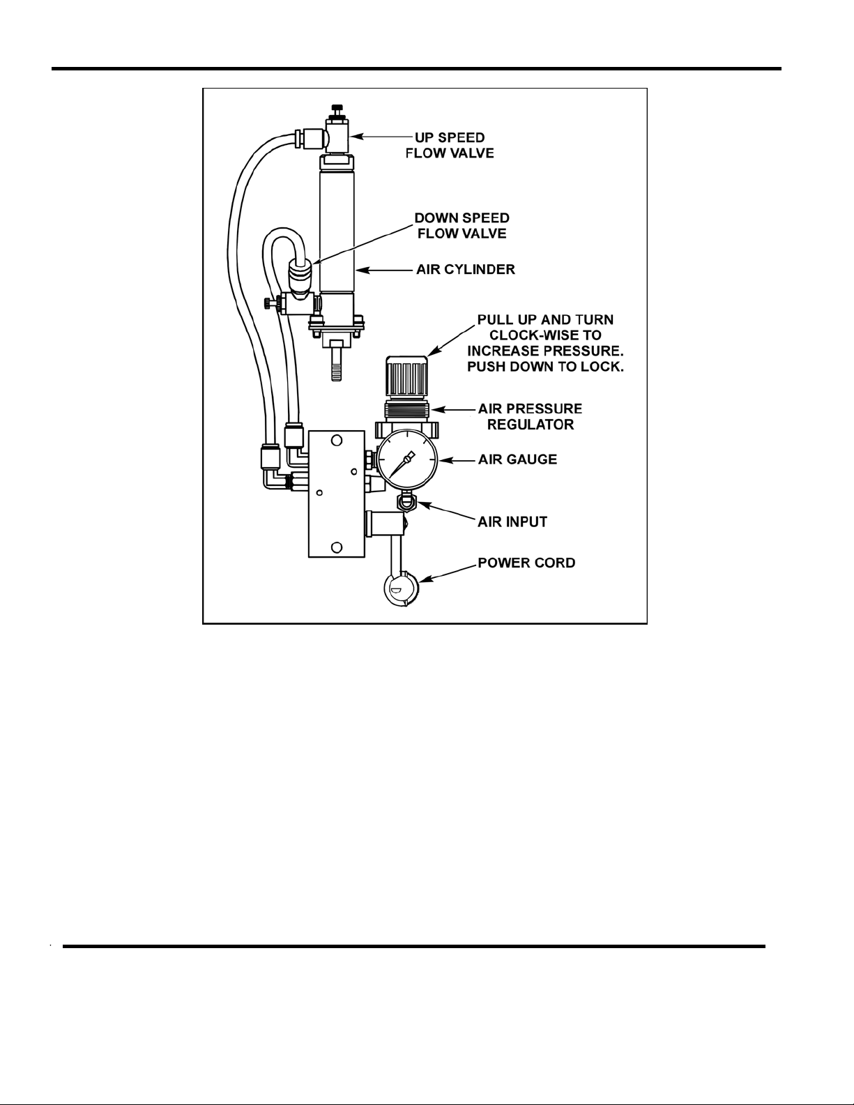
Air Actuated Weld Head Connections
Solenoid valve/regulator assemblies which are not mounted on the weld head should be located as close as
possible to the weld head. Use the shortest air lines possible to obtain the fastest mechanical response.
Connect the inlet port on the air valve (solenoid) to a properly filtered air supply (100 psig maximum). Use
0.25-inch OD plastic hose with a rated burst pressure of 250 psi to connect the outlet ports of the
solenoid/regulator assembly to the flow controls on the air cylinders. Figure 2-4 illustrates a typical single
regulator installation for a Unitek Peco Series 80 Weld Head. Turn the regulator(s) fully counter-clockwise
to ensure minimum air pressure. Turn on the air supply. Repair leaks if necessary.
All Thinline weld heads are capable of cycling at a rate of 1 weld per second, provided that the tubing
between pressure regulators and the air cylinder is kept as short as possible. Increasing the length of the
tubing produces very sluggish mechanical motion. Do not use lubrication on the input air line because, as
the internal seals on the air cylinder wear, lubricating oil will leak past these seals and contaminate the
electrode and the workpiece with a fine oil mist. Once every six months or every 1 million operations,
whichever occurs first, remove the top flow control valve and place two drops of light machine oil in the top
of the air cylinder.
MODEL 250DP DUAL PULSE
RESISTANCE WELDING POWER SUPPLY
990-280 2-5
CHAPTER 2: INSTALLATION
Figure 2-4. Typical Solenoid Air Valve Assembly with
a Single Regulator
Air Valve Driver
Connect the solenoid air valve to the AIR VALVE DRIVER 1 receptacle located on the rear panel of the
250DP. Weld heads with 4-pin 24/115 VAC connectors can be plugged directly into the power supply.
Weld Heads with standard 115 volt plugs (NEMA 5-15P) require an adapter, Unitek Peco Model
VDAC, Valve Driver Adapter Cable. When the connection has been made, the 250DP will
automatically recognize that an air head has been connected.
MODEL 250DP DUAL PULSE
RESISTANCE WELDING POWER SUPPLY
2-6 990-280

CHAPTER 2: INSTALLATION
Non Unitek Peco Air Actuated Weld Heads
Users of air actuated weld heads not manufactured by Unitek Peco should connect the air solenoid valve
on the head or regulator valve assembly to either the appropriate 24 volt or 115 volt pins of the
receptacle on the rear of the 250DP. Refer to Appendix A under Control Signals for detailed
information.
Air Actuated Weld Heads without Force Firing Switches
Users of air actuated weld heads not having force firing switches must use sufficient squeeze time to
allow the head to close and to apply the proper force to the workpieces.
Second Air Head
Connect the solenoid air valve of a second air actuated Unitek Peco weld head to the AIR VALVE
DRIVER 2 receptacle. Only weld heads with 4-pin 24 VAC connectors can be plugged directly into the
power supply.
Users of air actuated weld heads not manufactured by Unitek Peco should connect the air solenoid valve
on the head, or regulator valve assembly, to the appropriate 24 volt pins of the receptacle on the rear of
the 250DP. Refer to Appendix A under Control Signals for detailed information.
Footswitch
Connect either a 1-Level or 2-Level Footswitch to the FOOTSWITCH receptacle located on the rear panel.
The 250DP will automatically recognize which type Unitek Peco Footswitch has been connected.
1-Level Footswitch
When the operator fully depresses the 1-level footswitch, the 250DP will energize the air valve on the
weld head. The upper electrode will close and apply force to the workpiece. If the operator releases the
footswitch before the weld head applies the preset firing force, the 250DP will remove the voltage from
the air valve and the upper electrode will return to the open position.
If the FOOTSWITCH WELD ABORT option has been set to ON by changing the status on the
OPTIONS menu, the welding sequence will be terminated if the footswitch is released before the
welding sequence is completed.
If the FOOTSWITCH WELD ABORT option has been set to OFF, the welding process will continue to
its conclusion, regardless of the position of the footswitch, once the preset firing force has been applied
to the workpiece by the upper electrode of the weld head.
MODEL 250DP DUAL PULSE
RESISTANCE WELDING POWER SUPPLY
990-280 2-7

CHAPTER 2: INSTALLATION
2-Level Footswitch
When a 2-level footswitch is pressed to the first level, the weld head will close and apply force to the
workpiece. At this point, if the operator does not press further (harder) and actuate the second level, the
footswitch can be released so that the workpiece can be re-positioned. Once the second level has been
actuated, a 2-level footswitch will operate in the same manner as a 1-level footswitch.
Remote Schedule Selection
A 15-pin, subminiature D-type CONTROL SIGNALS connector, located on the rear panel, is provided for
seven single-pole inputs which are used to:
x Remotely select Weld Schedules 1 through 127 in a binary sequence.
x Remotely inhibit (prevent) the flow of weld current, which is the same function provided by the front
panel WELD/NO WELD Switch.
x Invoke the emergency stop condition, which abruptly terminates the welding sequence. Refer to
Appendix A, under Control Signals, for detailed connector information.
Relay Outputs
Two output relays can be used to provide status (timing) signals to external devices. They can also provide
an on (closed) state during a Run state or if there is an alarm.
Relay 1 can also be used to control a second 24 VAC air actuated weld head. (Refer to Air Actuated Weld
Head Connections for the appropriate hook-up connections and figure 4-5 for appropriate jumper
connections.)
Relay 2 can provide a 5 to 50 VDC signal.
When used to provide status (timing) signals, the relays can be independently programmed as follows:
x In Basic Mode, each relay can be programmed on (closed) or off (open) during either of the two weld
periods.
x In Roll Spot Mode, each relay can be programmed on (closed) or off (open) during either of the two
weld periods or during the cool period (between each spot weld cycle).
x In Repeat Mode, each relay can be programmed on (closed) or off (open) during either of the two weld
periods or during the off period (between each Repeat cycle).
In all of the above cases, if the relay is programmed to be on (closed), it will close at the beginning of the
scheduled period and open at the end of that period. If scheduled to be closed during any successive
periods, it will not open at the end of the first period, but will remain closed during both (or all) periods for
which it is scheduled to be closed.
MODEL 250DP DUAL PULSE
RESISTANCE WELDING POWER SUPPLY
2-8 990-280
CHAPTER 2: INSTALLATION
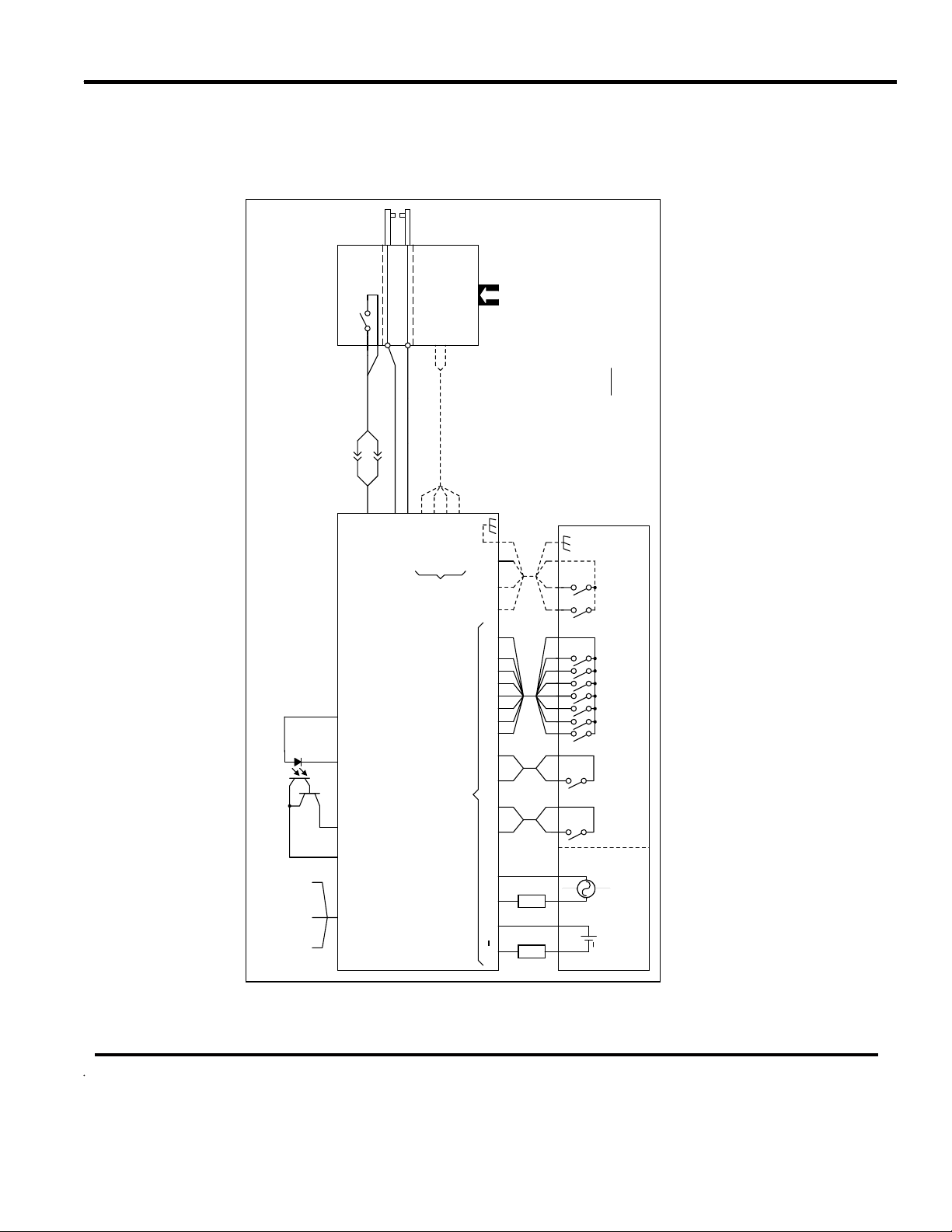
Interconnection Diagram
Refer to figure 2-5 for a wiring diagram of the 250DP as it is interconnected with external equipment.
Weld Head
Force firing switch
Footswitch
0
1
2
3
4
5
6
GND LV1 LV2 COM
2
2
2
2
2
2
input
Pneumatic
1
Notes:
1. Tie weld cables together.
0
1
2
3
4
5
6
on the firing switch connector.
2. For non-force-fired operation, short pns 1 and 2
L1 L2
2
2
2
2
2
2
2
switch connection is not used.
3. If an optical firing switch is used, the firing
Initiate
Weld schedule
connections.
4. Dashed lines represent air actuated weld head
select
User-supplied
Programmable Logic Control
(See note 2)
1
Electrodes
Air solenoid
24/115V AC
(See note 2)
2
(See note 4)
Weld cables (See note 1)
234
1
Return
24V AC
115V AC
Power output
Firing switch cable
Auto sense
driver
Air valve
Stop
Emergency
Control signals
234 5
250DP
Firing switch (See note 3)
1
Power NO COM NC +5V DC COM
50/60 Hz, 1Ø
115V AC, 15A
HOT COM GND
(BLK)(WHT)(GRN)
Power Supply
Load
DC+DC AC AC IN B GND EMR GND 2
Load
13 6 15 8 9 11 10 11 145124321 11 2 3 4 1
CHG
Inhibit
Relay 1
AC
24-115V DC
Relay 2
5-50V DC
power
User-supplied
+
Figure 2-5. 250DP Equipment Interconnection Diagram
MODEL 250DP DUAL PULSE
RESISTANCE WELDING POWER SUPPLY
990-280 2-9

CHAPTER 3
OPERATING CONTROLS AND SCREENS
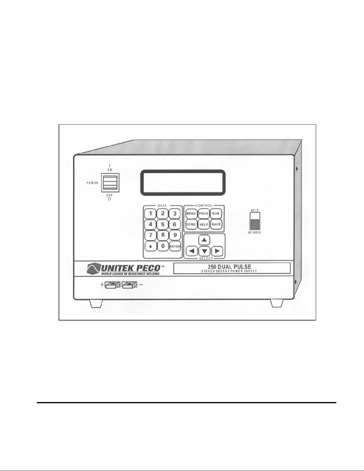
Operating Controls
Figure 3-1 illustrates the layout of the operating controls on the front panel of the 250DP.
Figure 3-1. Front Panel Controls
MODEL 250DP DUAL PULSE
RESISTANCE WELDING POWER SUPPLY
990-280 3-1

CHAPTER 3: OPERATING CONTROLS AND SCREENS
The controls on the front panel are identified as follows:
NOTE: Instructions in the manual to “press [ ]” means that you are to press the key or button described
inside the brackets. For example, “Press [PROG]” means that you should press the key labeled PROG on
the front panel. “Press [VW]” means that you should press either the W SELECT or the V SELECT key,
whichever is appropriate.
KEY DESCRIPTION
[KEYPAD] Use the 10 numeric keys to enter numeric information. [.] is used to enter decimal
values.
[VW] In the run state, this key changes ([V] increases and [W] decreases) the schedule
number displayed.
In program and menu states, the [V] and [W] SELECT keys are used to move up and
down on the screen to select fields.
] In the program and menu states, this key is used to select the parameter to the right
[
(
]) or left ( ]) of the parameter which is highlighted.
[PROG] Causes the 250DP to enter the program state so that you can make changes to
Schedules 0 through 127. If a Weld Sentry is installed, when [PROGRAM] is
pressed a second time, you can make changes to the Weld Sentry programs related to
each weld schedule. Press [PROGRAM] to return to the PROGRAM screen (refer to
Screen Formats next in this chapter).
[RUN] Causes the 250DP to exit the program state without saving the changed schedule.
The changed schedule will become Schedule 0 and will not be written to permanent
memory. If no changes are made to the schedule or the Weld Sentry program, then it
will not be transferred to Schedule 0. Welding is done in the run state.
[SAVE] In the program state, pressing this key saves (writes) any schedule and its related
Weld Sentry programs to permanent memory. The 250DP will then exit the program
state and return to the run state. This key has no function in the run state.
MODEL 250DP DUAL PULSE
RESISTANCE WELDING POWER SUPPLY
3-2 990-280
 Loading...