

Page 1

MAPS
Installation Guide
Page 2

Table of Contents
1 Introduction ................................................................................................................................ 3
1.1 Features ............................................................................................................................... 5
2 Environmental Requirements .................................................................................................. 6
2.1 Commissioning and Installation of the MAPS Beame .................................................. 7
3 Installation of PBS ................................................................................................................... 11
3.1 Part Numbers .................................................................................................................... 11
3.2 Description of connectors on FM 3xxxi ......................................................................... 12
3.3 Connection Sequence ..................................................................................................... 12
3.4 Commissioning and Installation of the PBS ................................................................. 13
3.5 Installation Requirements................................................................................................ 13
4 Verification................................................................................................................................ 13
5 Appendix A: Instructions how to replace the batteries ...................................................... 14
13 Jan 2016 V2 2 | P a g e
Page 3

1 Introduction
Asset + Beacon
MiX OBC + PBS in vehicle
MiX Fleet Manager
Beacon
Mobile Base Station
GSM/WiFi
RF
Customer Interface
This document is applicable to the MiX Asset Positioning System (MAPS).
MAPS enables all existing MiX Telematics installed vehicles to create a customer specific
wireless network, where each vehicle becomes a mobile beacon reader, would not require
any additional effort on the customers part. As the vehicles move around the sites and
depots they would encounter beacon equipped assets and relay information about the
position of those beacons.
A single software platform, MiX Fleet Manager, enables the management of vehicles as
well as beacon equipped assets. In MiX Fleet Manager, asset managers are able to keep
track of where there assets have been deployed and are currently in use. Vehicles in the
vicinity of these assets will also be shown on the same tracking screen, should the fleet
manager need to efficiently coordinate the redeployment of an asset to a different location.
MAPS consist of the following hardware:
1) An RF network transceiver or Pico Base Station (PBS) that is added into the
wiring harness of any existing FM Communicator OBC to convert the vehicle to a
Mobile Base Station (MBS)
2) The Beame (also called the Magix Beacon): The Beame communicates with a
Mobile Base Station (MBS) or stationary as a Fixed Base Station unit (FSB) via a
radio link. The MBS and FSB communicate with a remote server via a GSM link.
The Beacon is a wireless battery operated product. It is therefore easy to install.
The variant of Beame that is fitted with a GPS is called a “MAPS Beame”.
13 Jan 2016 V2 3 | P a g e
Page 4

Figure 1–Picture of the MAPS Beame
13 Jan 2016 V2 4 | P a g e
Page 5

Figure 2–Picture of the Pico Base Station (PBS)
1.1 Features
The MAPS Beame is fitted with a movement sensor and a build-in GPS
The MAPS Beame has a battery low detection. Should the battery become depleted,
the information will be sent to a server and communicated to the user with instruction
how to rectify it.
The PBS fits in line between the FM OBC and the Code Plug socket.
13 Jan 2016 V2 5 | P a g e
Page 6

The PBS is connected to the vehicle battery. An optional T-piece exists to allow the
installer to connect to power via the existing wiring.
2 Environmental Requirements
The MAPS Beame can be installed in places where it is exposed to water jets and
temporarily immersion into water.
The MAPS Beame was designed to endure standard transport vibration and shock.
The MAPS Beame can endure a limited number of accidental drops
The PBS is not water tight and was designed to be installed together with the FM
OBC (non-wet areas).
The operating temperature for PBS and MAPS Beame is between -20 and 85 ºC.
13 Jan 2016 V2 6 | P a g e
Page 7

2.1 Commissioning and Installation of the MAPS Beame
The unit is battery operated and no wire connections are needed to install the unit. To
install the unit:
1) Rotate the MAPS Beame at least 10 times left and right in the longitudinal axis through
180° (see Figure 3 below).
Figure 3–Activation of MAPS Beame
13 Jan 2016 V2 7 | P a g e
Page 8

Once the unit is
activated, the
LED indicated
by the arrow,
will flash for
about 10 s to
indicate that
the unit is
activated
2) After about 10 rotations through 180°, the LED beneath the window will flash for about
10 s to indicate that the unit has started up (see Figure 4 below).
Figure 4–Flashing diode to indicate MAPS Beame is active
3) If the MAPS Beame is installed in conjunction with a PBS (which is not always the case), then first pair
the MAPS Beame with the PBS as described in section 3.4.
13 Jan 2016 V2 8 | P a g e
Page 9

4) The MAPS Beame must be installed with the GPS side (lid side) faces towards the sky.
a) For a vertical mount (see Figure 5 below).
b) For a horizontal mount, the label side should face towards earth and the round
side should face towards the sky (satellites) (see Figure 6).
Figure 5– Vertical Mounting of Unit
13 Jan 2016 V2 9 | P a g e
Page 10

Figure 6– Horizontal Mounting of Unit
5) Place the unit in a concealed position, preferably at least 20 mm away from metal for
improved performance.
6) The MAPS Beame should preferably not be obscured from the satellites by metal. If it
is partially obscured it might still work well.
7) Use the MAPS Beame Installation Tool to verify that the MAPS Beame is switched ON
and that it has adequate RF and GPS signal strength.
13 Jan 2016 V2 10 | P a g e
Page 11

3 Installation of PBS
Part Number
Product Name
Description
440FT0947
Pico Base Station
Interface Harness
Interface between the 6-pin micro fit connector on
PBS and the Code Plug Socket Harness
440FT0964
Magix Pico Base
Station Type 9
PBS Electronic Unit
440FT0965
Magix Pico Base
Station Type 9 Kit
Kit consisting of PBS Electronic unit plus PBS
Interface harness (440FT0947) and the PBS Power
Harness (440FT0966)
440FT0966
Pico Base Station
Power Harness
Connects the PBS Electronic unit to vehicle battery
power
440FTZ035-1
(new: 440FT0945)
Code Plug Socket
Harness
Connects to the PBS Interface harness
(440FT0947) or alternatively to the FM300 Code
Pug Harness
440FT0930
Code Plug
Harness CP2
Connects between the PBS (4 pin) to the FM 3xxxi
Code Plug connector (4 pin micro fit)
3.1 Part Numbers
The PBS consists of the following part numbers.
13 Jan 2016 V2 11 | P a g e
Page 12
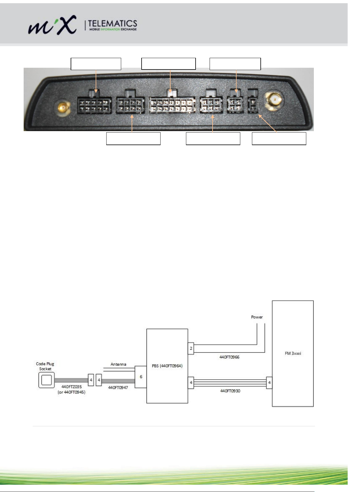
3.2 Description of connectors on FM 3xxxi
Serial
Main
Code Plug
Auxiliary
Audio
J1708
Figure 7– Connectors on FM 3xxxi
3.3 Connection Sequence
Refer to connection diagram in Figure 8:
1) The standard Code Plug Harness CP2 (440FT0930) is to be connected to the 4-pin
“Code Plug” connector on the FM 3xxxi (refer to Figure 8).
2) The other end of the Code Plug Harness CP2 is connected to the 4-pin on the PBS
(see Figure 8).
3) On the same side of the PBS, connect to the 2 pin connector the PBS Power
harness (440FT0966) (Note: there is also an optional power harness that allows
one to connect to the 10 pin “Serial” connector on the FM 3xxxi (refer to Figure 8).
4) Connect the “PBS Interface” Harness (440FT0947) to the 6-pin connector on the
PBS
5) Connect the other side (4-pin) of the “PBS Interface” Harness to the “Code Plug
Socket” harness (440FTZ035) (there is a newer harness under development,
namely 440FT0945).
Figure 8– Connection diagram for PBS
13 Jan 2016 V2 12 | P a g e
Page 13

3.4 Commissioning and Installation of the PBS
1) Refer to section 2.1 on how to activate a MAPS Beame.
2) A special grey coloured plug exists that is used to program the “Org. ID” into nearby
MAPS Beame units
3) The grey coloured plug must be inserted into the code plug socket to allow the
process to start
4) Once the plug is inserted, the code plug socket LED will flash every 500ms (or at a
rate of 2Hz) to indicate that the PBS is in Org. ID programming mode.
5) The PBS will now program the MAPS Beame with the Org. ID. Bring the MAPS
Beame close to the PBS. The MAPS Beame will flash to indicate that it has been
programmed with the Org. ID.
6) The PBS will now verify that the correct Org. ID is loaded on the MAPS Beame.
Keep the MAPS Beame close to PBS until the code plug LED goes ON.
7) The MAPS Beame is now loaded with the Org. ID of the FM and has been verified
by the PBS.
3.5 Installation Requirements
1) Do not fit a GSM antenna onto the PBS Enclosure
2) Do not fit a GSM antenna closer than 100 mm from the PBS
4 Verification
After the installation, verify that no interference is caused to the vehicle’s electrical system
or remote locking key. Check dashboard warning lights and error messages. Should any
error conditions exist, remove the Beame and contact MiX Telematics for assistance.
13 Jan 2016 V2 13 | P a g e
Page 14

5 Appendix A: Instructions how to replace the batteries
1) Hold the Beacon (preferably in a vice to avoid injuries) and then use a thin flat screw
driver to open the unit as shown in below. A second screw driver (or a finger nail can
be used to keep the lid open)
Figure 9 Opening the lid with a thin flat screw driver
13 Jan 2016 V2 14 | P a g e
Page 15

2) Pull out the plastic tray containing the 2 x AA batteries as shown below in Figure 10.
Figure 10 Open unit
13 Jan 2016 V2 15 | P a g e
Page 16

3) Remove the flat batteries using a flat screw driver as shown below in Figure 11.
Important: Dispose old batteries in a designated disposal bin. If there are any signs of
battery leakage, is recommended to replace the unit with a new one.
Figure 11 Remove old batteries
13 Jan 2016 V2 16 | P a g e
Page 17

4) Insert new batteries. It is important not to contaminate the battery terminals by
touching them with bare fingers (that may for example contain residue of hand cream).
It is very important to insert the batteries with the correct orientation as marked on the
PCB. The easiest way to insert it is shown in the picture below (Figure 12).
Figure 12 Insert batteries
5) Ensure that the LED flickers when the batteries have been replaced. If it does not
flicker then the batteries could be flat or it was inserted the wrong way round. If this is
the case then remove the batteries and put it in the correct way. There is reverse
voltage protection. If necessary replace the Beacon with a new one.
6) Install the unit again as per instructions in section 2.1.
13 Jan 2016 V2 17 | P a g e
 Loading...