

Page 1

Tabs Beacon
Installation Guide
Page 2

© 2016 MiX Telematics International (Pty) Ltd.
Table of Contents
1 Introduction .................................................................................................................. 3
2 Environmental Considerations ..................................................................................... 3
3 Regulatory Compliance ............................................................................................... 3
4 Hardware Installation ................................................................................................... 3
4.1 Part numbers ......................................................................................................... 4
4.2 Activation Procedure and Beacon Install Mode ..................................................... 4
4.3 Installing the Beacon ............................................................................................. 5
Document Version: 6 2 | P a g e
Page 3

© 2016 MiX Telematics International (Pty) Ltd.
1 Introduction
The Tabs Beacon is a part of the MiX Tabs solution. The beacon is
wireless and battery operated making it easy to install. It is also fitted with
a movement sensor and a built-in GPS. The beacon communicates, via
a radio link, with a Mobile Base Station (MBS) or a Fixed Base Station
(FSB). The MBS and FSB network relay the beacon information to the
remote server via a GSM link.
2 Environmental Considerations
The Tabs Beacon can be installed in places where it is exposed to water jets and temporary immersion
into water.
The Tabs Beacon was designed to endure standard transport vibration and shock.
The Tabs Beacon can endure a limited number of accidental drops.
The operating temperature for the Tabs Beacon is between -20 and 85 ºC.
3 Regulatory Compliance
This device complies with Part 15 of the FCC Rules. Operation is subject to the following two conditions: (1)
this device may not cause harmful interference, and (2) this device must accept any interference received,
including interference that may cause undesired operation.
No changes / modifications shall be made to the equipment without the manufacturer’s permission as this
may void the user’s authority to operate the equipment.
This equipment complies with FCC radiation exposure limits for an uncontrolled environment. This
equipment shall be installed and operated with a minimum distance of 20 cm (7.9 in) between users and/or
bystanders and the device.
4 Hardware Installation
The unit is battery operated and no wire connections are needed to install the unit. The Tabs Beacon
product has been designed for tracking and locating mobile assets typically in a vehicular environment.
The only time this product should come into physical contact with the user is during activation. After
activation the Tabs Beacon must be mounted in a suitable location greater than 20cm away from the user
and bystanders to prevent tampering.
IMPORTANT: This product must not be used for tracking personnel.
Document Version: 6 3 | P a g e
Page 4
© 2016 MiX Telematics International (Pty) Ltd.
4.1 Part numbers
Part
Number
Name
Description
Picture
440FT0962
Tabs Beacon
B59B
Tabs Beacon B59B Electronic Unit
(Frequency 915 MHz)
440FT0997
Tabs Beacon
B54B
Tabs Beacon B54B Electronic Unit
(Frequency 433 MHz)
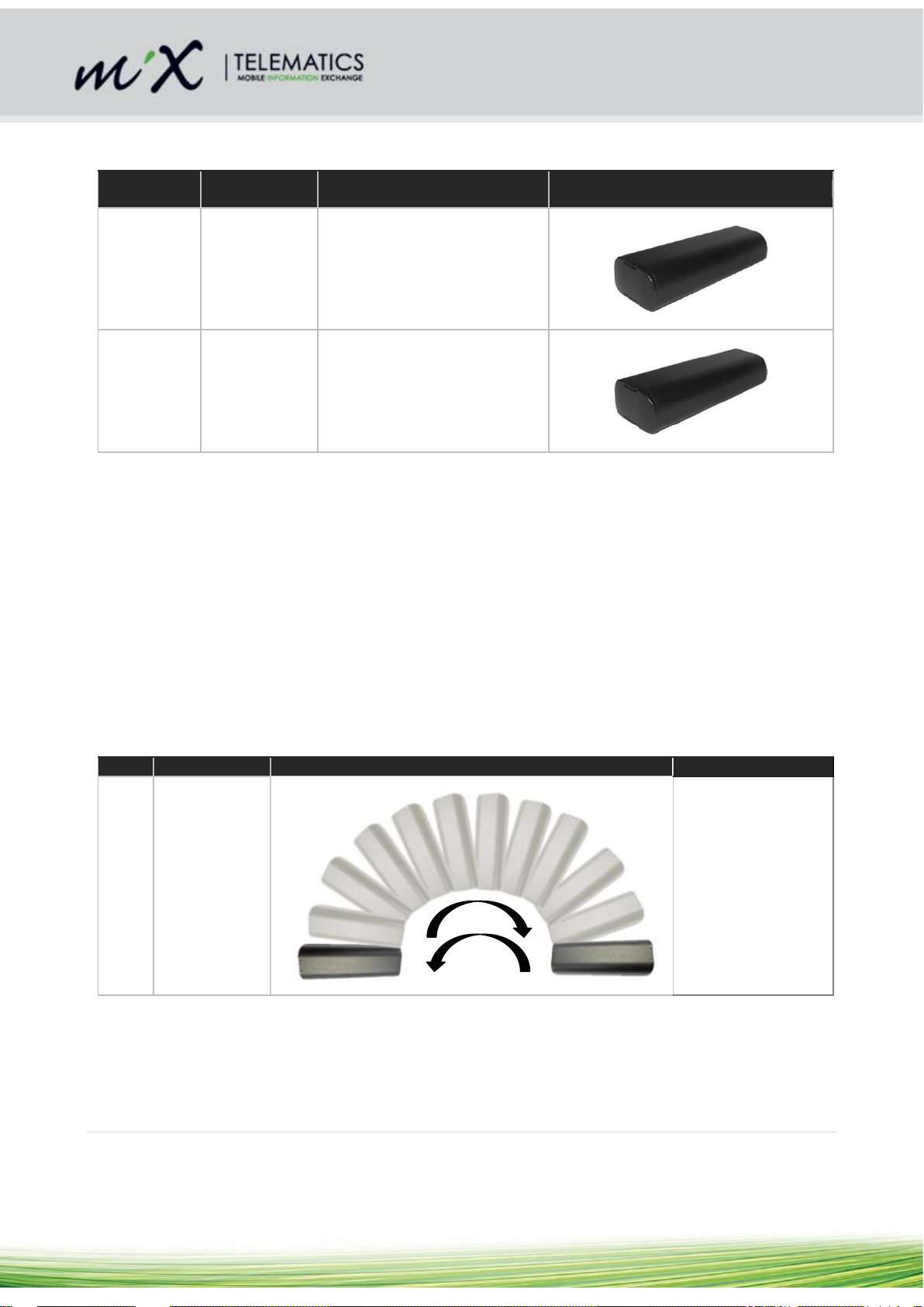
Step
Part Number
Picture
Description
1
440FT0962 or
440FT0997
Rotate the Tabs
Beacon at least 10
times to the left and
right in the
longitudinal axis
through 180°,
changing direction
once every second
4.2 Activation Procedure and Beacon Install Mode
The beacon is supplied in a shipping mode from the factory. In this mode it is completely inactive and needs
to be activated before it is installed or it will not be functional. Activation is normally performed automatically
during the commissioning process when it is done by the Tabs Technician Tool. There is however also a
manual process that can be used to activate the beacon that involves rotating it in a specific way (see step 1
below).
The process of activation causes the Beacon to enter its install mode. Visual confirmation of this is provided
by the flashing of the red LED for 10 seconds (see step 2 below). In install mode the beacon will transmit
more frequently (every 8 seconds) to assist with confirming the success of the installation process. After 1
hour in Install Mode the Beacon will automatically revert to normal operation. Install Mode can be
reactivated at any time simply by repeating the activation process.
Document Version: 6 4 | P a g e
Page 5
© 2016 MiX Telematics International (Pty) Ltd.
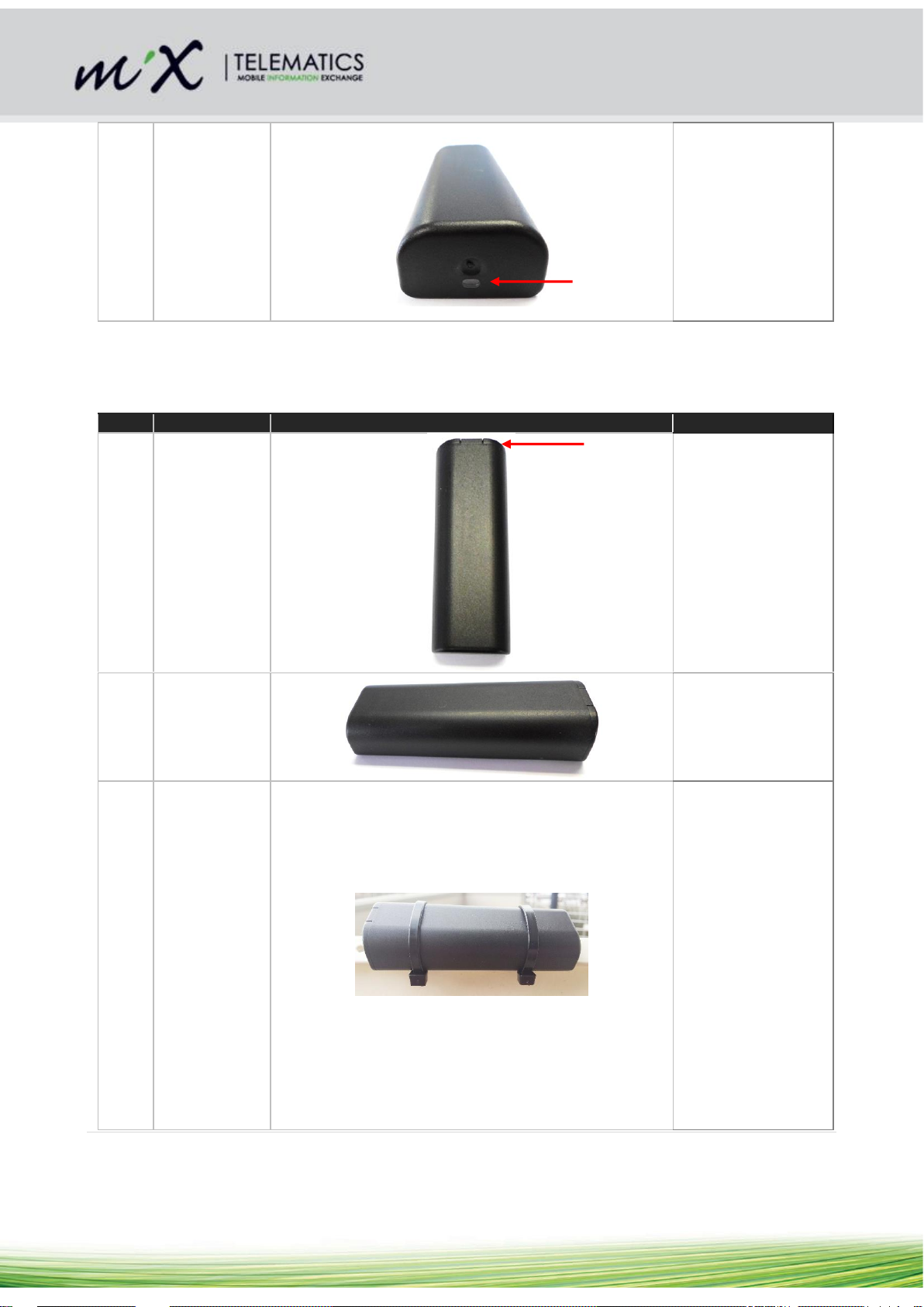
2
440FT0962 or
440FT0997
After about 10
rotations through
180°, the LED
beneath the window
will flash for about
10seconds to
indicate that the
Beacon has
activated and
entered its install
mode.
Step
Part Number
Picture
Description
1
440FT0962 or
440FT0997
For a vertical mount:
The Tabs Beacon
must be installed
with the GPS side,
the side where the
lid is, pointing
towards the sky.
2
440FT0962 or
440FT0997
For a horizontal
mount, the label side
should point towards
the ground.
3
440FT0962 or
440FT0997
Attach the beacon
securely to the asset
using at least two (2)
cable ties such as
RS Pro Black Nylon
Non-Releasable
Cable Tie, 300mm x
4.8mm RS Stock
no.233-487 or
similar. Cable tie
size may vary based
on installation
requirement.
Ensure that the
location selected
allows the beacon to
4.3 Installing the Beacon
Document Version: 6 5 | P a g e
Page 6

© 2016 MiX Telematics International (Pty) Ltd.
be mounted without
any metal obscuring
its view of the sky.
Care should also be
taken to select a
location on the asset
where the beacon is
least likely to be
damaged during
day-to-day use of
the asset
Document Version: 6 6 | P a g e
 Loading...