

Page 1

MiX 4000
Installation Guide
Page 2

Table of Contents
1 Introduction ................................................................................................................................ 3
1.1 Glossary Terms .................................................................................................................. 3
1.2 MiX 4000 Hardware Features .......................................................................................... 3
1.3 MiX 4000 Power Requirements ....................................................................................... 4
2. Safety .......................................................................................................................................... 4
2.1 Installer Requirements ....................................................................................................... 4
3. Prior to Installation .................................................................................................................... 5
3.1 Preparing the SIM card ...................................................................................................... 5
3.2 Inserting of SIM card .......................................................................................................... 5
3.3 Configuration of unit ........................................................................................................... 5
3.4 Installation Steps ................................................................................................................ 6
4. Installation .................................................................................................................................. 6
4.1 During installation ............................................................................................................... 6
4.2 Positioning of product components ................................................................................. 6
4.3 General Wiring Requirements .......................................................................................... 8
4.4 Harnesses and connectors ............................................................................................. 10
4.5 Wiring and Connections .................................................................................................. 14
4.6 Code Plug Socket Installation ........................................................................................ 17
4.7 Signal Inputs...................................................................................................................... 18
4.8 Power Outputs .................................................................................................................. 19
4.9 Serial Communication ...................................................................................................... 21
4.10 CAN ................................................................................................................................. 21
4.10.1 Overview ..................................................................................................................... 21
4.10.2 Tools and Inspection need for CAN Installation ................................................... 21
4.10.3 Wire lengths ............................................................................................................... 22
4.10.4 CAN jumper settings ................................................................................................. 22
4.10.5 When must the 120 Ohm terminating resistor be in the circuit?........................ 25
4.10.6 General Rules for CAN terminating resistors ....................................................... 25
4.10.7 When must the RD/WR Jumpers be in the circuit? ............................................. 26
4.11 DLD and DTCO ............................................................................................................. 27
4.11.1 D-8 ............................................................................................................................... 27
4.11.2 Connect CAN to DTCO ............................................................................................ 27
4.11.3 K-line ........................................................................................................................... 28
4.12 Bluetooth ........................................................................................................................ 28
5. After Installation ................................................................................................................ 28
5.1 Beep codes ........................................................................................................................ 28
5.2 LED flash codes................................................................................................................ 29
5.3 Testing Installation ........................................................................................................... 30
6. Troubleshooting ....................................................................................................................... 30
7. Routine Maintenance.............................................................................................................. 31
8. MiX 4000 Specifications ......................................................................................................... 31
8.1 Technical description ....................................................................................................... 31
8.2 Auxiliary inputs/outputs.................................................................................................... 32
2 | Page
Page 3

8.3
Inserting a Backup Battery .............................................................................................. 33
1 Introduction
The MiX 4000 is a high end Fleet product that incorporates the latest market trends.
1.1 Glossary Terms
ABBREVIATION DESCRIPTION
BT
DLD
DTCO
GPS
GSM
GND
RX
TX
WiFi
BT
Bluetooth
Download Device
Digital Tachograph
Global Positioning System
Global System for Mobile Communications
Ground (0V)
Receive
Transmit
Local Area Wireless Computer Network
Bluetooth
1.2 MiX 4000 Hardware Features
Digital/Analog Inputs
Frequency Inputs
Tacho Inputs
Ignition input
CAN
GNSS
GSM
Serial Ports
K-line and D8
Bluetooth
Accelerometer
Positive drive
Tamper detection
Code Plug
There are 2 analogue inputs can be configured to monitor any device that
generates a change in voltage, e.g. seat belts, headlights, refrigeration units,
temperature sensors, emergency lights, doors, PTO, UDS, trailer coupling
etc. Disconnection of these inputs can be detected using open-wire detect.
There are 2 x frequency/pulse inputs for integration with legacy sensors exist
It is possible to configure any of the 4 existing inputs listed above
(Digital/Analogue and Frequency) as tacho inputs
Used to monitor the ignition switch status. Maximum 36V input, impedance >
100kOhm. The unit is able to detect when the Ignition gets connected or
disconnected. Disconnection of this input can be detected with open-wire
detect.
The system has 2 x CAN inputs that support J1939 and OBDII CAN as a
minimum. Configuration of the termination resistor and the transmit disable
can be done either with jumpers (for safety critical installs) or via software
settings.
GPS and Glonass available
3G UMTS/HSDPA/HSUPA Characteristics
2x RS232 serial ports (with flow control)
K-line interface for Digital Tachograph (DTCO D8 input)
Support Bluetooth V4 and CSA2
3-axis ±2g /±4g / ±8 g / ±16 g dynamically selectable full-scale and is
capable of measuring acceleration with output data rates from 1 Hz to 5 kHz
4 x Positive drive with open-load detect and current sense diagnostics, 1x
with 1.5A current limit and 3x with 250mA current limit
Tamper detection when the housing is opened (covers removed). Shorting,
cutting, or unplugging any of the external antennas can also be detected.
Standard FM code plug circuit (Optional: 5V aux output)
Only Blue Driver plug supported.
3 | Page
Page 4

Internal Back up battery
Buzzer and LED
RF Transceiver
RTC
1.3 MiX 4000 Power Requirements
The MiX 4000 is designed for use in 12V or 24V vehicles. Special vehicles and working machines with
voltages above 33V will require a voltage converter to facilitate the required power supply input.
2. Safety
2.1 Installer Requirements
Installation should only be undertaken by a vehicle technician with comprehensive occupation
specific knowledge. Installation by an unqualified technician may adversely affect the operating
reliability of the vehicle and could endanger other road users.
A basic knowledge of vehicle electrical and mechanical systems is required to successfully install
the Fleet Manager system.
The system should only be installed by a suitably qualified vehicle technician with a basic knowledge
of the operation of computers.
Installation technicians should attend a training course to acquire the skills needed for installation,
configuration and operation of the Fleet Manager system.
An internal battery provides power for more than 8 hours if the supply from
the vehicle’s battery is removed.
A Buzzer is available to warn the driver and to provide feedback of the
vehicle’s status. 2 x LEDs at the back provide feedback on the status of the
unit.
433 or 915 MHz RF transceiver
Real time clock with coin-cell battery
Installers should consult the vehicle manufacturer’s documentation for the specific vehicle make and
model prior to undertaking an installation.
Installers should pay particular attention to the location of fuel systems, hydraulic systems,
compressed air systems and other electrical and mechanical systems, which may have a bearing on
the installation.
Installers should pay attention to any changes to the vehicle’s systems or settings, which should be
noted prior to the installation.
Installers should not smoke or make use of naked flames, which could cause a fire in or near the
vehicle.
After installation, verify that no interference is caused to the vehicle’s electrical system. Check dashboard
warning lights and error messages. Should any error conditions exist, remove the installed unit and contact
MiX Telematics for assistance.
2.1.1 Tools
Standard technical equipment and appropriate tools for use with vehicles are required to install
the MiX 4000.
Vehicle specific tools may be required for the removal of consoles and covers.
Supporting tools
o Multi-meter
2.1.2 Secure the workplace
Remove the ignition key from the vehicle’s ignition lock.
4 | Page
Page 5

Ensure that the vehicle’s engine cannot be unintentionally started during the installation.
Short-circuiting the vehicle’s electrical system may result in fire, explosion of the battery and/or
damage to other electrical systems.
Electrical shock from high voltage batteries must be avoided, as this may lead to death or injury.
The negative terminal of the vehicle’s battery should be disconnected before commencing
installation. If the vehicle has additional batteries, it may be necessary to disconnect the
negative terminals of these batteries too.
2.1.3 Precautions
2.1.3.1 ESD
Prior to touching the PCB, inserting a new SIM or replacing the battery, always take ESD precautions:
Either use an earthed wrist strap or touch a known earth point (or negative potential in the
vehicle) prior to handling the unit
If the PCB must be handled, avoid direct contact with any of the components and handle it by
only touching the edges of the PCB
3. Prior to Installation
3.1 Preparing the SIM card
Before inserting the SIM card determine if the SIM needs to be secured with a unique PIN
If a PIN secured SIM is required
Ensure that the SIM is configured as “PIN required”
Ensure that the PIN is set as either 0000 or 00000
The MiX 4000 will change the PIN to a unique number that it calculates for the device
The SIM is then locked to the device and will be PUK locked if inserted in another device
If an unsecured SIM is required
Ensure the SIM is configured as “PIN not required”
The MiX 4000 will leave the SIM with this configuration
This SIM can be moved to a different device without risk of it being PUK locked
3.2 Inserting of SIM card
In order to insert the SIM card, the following steps must be followed:
Observe ESD precautions as prescribed in section 2.1.3
The SIM card is accessible from the back panel.
Insert the SIM card as indicated by the engraved symbol on the housing plastic.
3.3 Configuration of unit
The MiX 4000 is configured with default fleet settings during commissioning. Via the MiX Fleet Manager
software interface it is possible to make over the air changes to some settings.
5 | Page
Page 6

3.4 Installation Steps
Step Action Software Tools
1)
2)
3)
4)
5)
6)
7)
8)
9)
10)
11)
12)
On the MiX 4000, the unit maintains an on-board odometer. This starts at 0 km from the factory. An offset
can be sent from the MiX Telematics Fleet Manager user interface to align the odometer value on the MiX
4000 unit with the vehicle odometer at install time using the Bluetooth installation tool. An updated value can
be sent at any time over the air from Dynamix to realign these two values.
4. Installation
Ensure the SIM is correctly prepared (refer to section 3.1) None
Insert the SIM card (refer to ESD precautions in section 3.2). The
SIM card orientation is illustrated in section 3.1
Configure the unit as described in section 3.3 Dynamix
Configure Bluetooth if applicable (section 4.12) Bluetooth Installation Tool
Install harness None
Install code plug socket None
Install GPS antenna None
Connect power and signal inputs None
Test Installation Verify that the unit reports
Test GSM observing the LED flashing sequence (see section 5.2) None
Test GPS observing the LED flashing sequence (see section 5.2) None
Install unit
None
to the Back End
4.1 During installation
Should it be necessary to remove seats, covers or other components, care should be taken to avoid
accidental damage and/or disconnection of cables.
All components should be checked for damage prior to being installed into the vehicle.
For small installation openings, a drill should be used.
For larger openings, a conical milling cutter, compass saw or file should be used.
All rough edges should be trimmed.
Careful attention must be paid to the manufacturers’ safety regulations for all tools used.
Oils and fuels must be collected in appropriate containers and disposed of in accordance with
the law.
4.2 Positioning of product components
Installers should ensure that the components of the product do not influence or hamper the functioning of
the vehicle’s systems.
Care should be taken to ensure that the product’s components do not get damaged during
installation.
Ensure that sufficient space is available for all components of the product, prior to
commencing the installation.
6 | Page
Page 7
Should the bracket be used to fix the unit to the vehicle, make sure that the unit and bracket
are securely clipped together. Add a cable-tie around the complete housing and bracket
assembly for a more secure mounting it required.
Avoid installing in known high-temperature areas, such as parts of the engine bay or near
major heat sources.
o Operating range (with backup battery): -20°C to +60°
o Operating range (without backup battery): -20°C to +80°
o Battery will only charge in the range 0°C to +45°C
Ensure that the unit and harness are secured to prevent the harness vibrating differently to
the unit at the harness connectors.
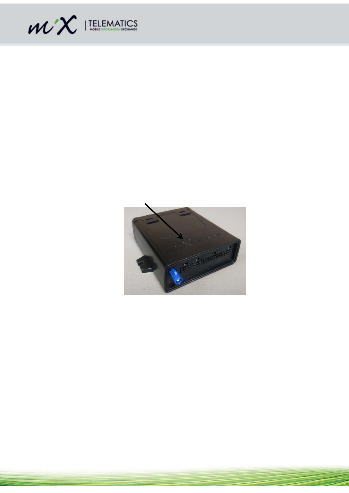
Correct orientation of the unit is important to ensure good GPS reception if the internal GPS
antenna is being used (it is not a problem if the external antenna is used). In this case where
the internal antenna is used, the unit should be mounted with the top side (with
MiXTelematics engraved) facing up, and the label side down. Additionally, it is advisable to
install the unit in a location where the GPS view of the sky is relatively unobstructed by metal.
Most vehicle boots for example, may form a metal cage which prevents GPS reception. Under
the vehicle bonnet will also not give good performance.
Engraved side facing up
Please note that the voltage of the external relay is rated to the vehicle voltage specification.
Do not run a 12V relay at 24V. The Relay Specifications are:
o Coil current rating: < 250 mA
o Coil Voltage Rating: Must match the vehicle battery supply
Please pay attention to the routing course of cables and wiring.
Do not install the product in or near the location of mechanical or electrical airbags.
Do not install the GSM antenna onto any cable or metal parts (it only applies to optional
external GSM).
Do not drill into supporting or stabilizing braces or beams.
7 | Page
Page 8

4.3 General Wiring Requirements
Note the product’s wire gauge cross-sectional area. If the wire gauge cross-section is reduced, current
density increases which may cause the wiring to overheat.
Cables should be routed in existing channels and should not be routed parallel to ignition cables
or other cables subject to high current.
Cables should be fixed with cable-ties or adhesive tape.
Do not route cables over moving parts or too close to the high voltage areas (like the spark
plugs)
Do not fix cables on the steering column.
Ensure that the cables are not exposed to pulling, pressure or shearing deformation.
If the cables are routed through drilled holes, rubber grommets or similar protection should be
used.
Suitable cable-strippers should be used to strip insulating material from cables and cable-
strippers should be adjusted to suit the wire gauge being stripped, to avoid damaging or
separating the wire strands.
Cables should only be connected using solder or suitable crimping lugs.
A proper crimping tool should be used on all crimping lugs.
Careful attention must be paid to the manufacturers’ safety regulations for all tools used.
Insulate all exposed wires to prevent short-circuits. Use good quality adhesive tape or heat
shrink (provided).
Connections to vehicle power supply must be installed with a fuse (check if the main harness is
fitted with a fuse).
Be aware that short-circuiting may be caused by faulty connections and crushed or damaged
cables.
Short-circuiting the vehicle’s electrical system may result in fire, explosion of the battery and/or
damage to other electrical systems. To prevent this, all connections carrying current must be
soldered and insulated correctly. Other connections such as the speed signal, RPM signal,
brake light or clutch switch can be made with crimping lugs.
Incorrect connections can lead to short circuits. Connections should only be made in
accordance with the vehicle’s wiring diagram.
Current and voltage should be measured with a multi-meter or diode test lamp.
The use of inadequate test equipment may result in damage to control devices or other
electrical systems.
Route the harness in such a way as to prevent water condensation that may form on the cable
from running into the unit. This can be achieved by having the harness at a lower point just
before it connects to the unit. If the back plate is lower than the rest of the unit, water can
accumulate inside the unit with no way to escape and invalidates the IP54 rating. The unit
should also never be exposed to direct water spray and jets.
Shortening of antenna wires:
o It would be better to circle/coil excess wires. Avoid sharp bends at the zig/zags. Take
care not to tie coax wires too tight. The coax should not be squeezed or pinched. Using
the broadest possible cable tie.
o The best place to circle/coil the wires is about 300 mm in line from the antenna.
8 | Page
Page 9
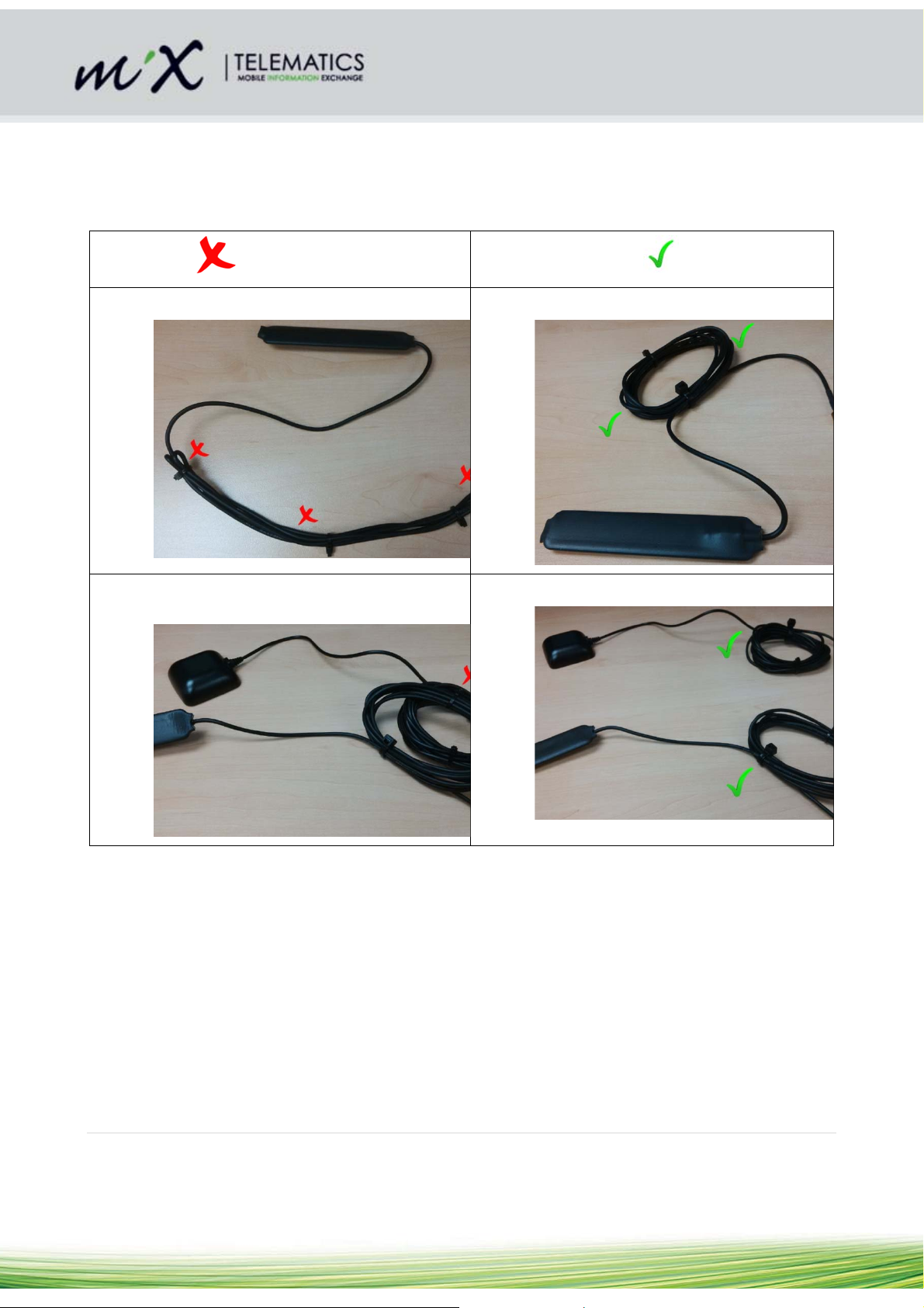
o If the GSM and GPS antennas are both coiled, they should be spaced apart.
o Refer to section 4.4.7 for more detailed GPS wiring instructions
o Refer to section 4.4.8 for more detailed GSM wiring instructions
Avoid
Avoid sharp corners and bends: Use rounded bends:
Avoid coupling between 2 different pieces of
wire:
Recommended
Separate coiled wires where possible:
9 | Page
Page 10
4.4 Harnesses and connectors
Please read the “Safety” section of this document before installing the vehicle harness.
Confirm which of the harnesses will be used in the install as the wire colours will differ depending on the
harness selected. All connector diagrams are shown from the back (wiring side) of the harness.
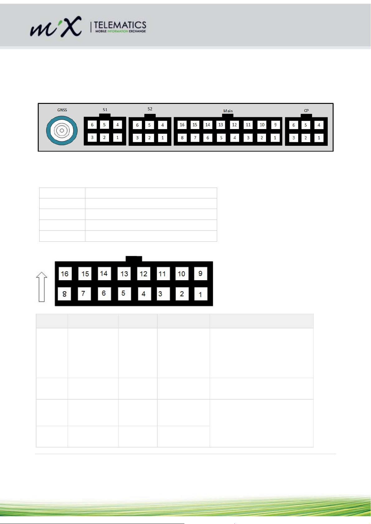
Below is the front view of the MiX 4000.
The pin lay-out and wire colours of the various harness options as well as detailed tables describing pin
functions are shown below.
4.4.1 Harness Part Numbers
440FT0982
440FT0930
440FT0931
440FT0933
440FT0945
4.4.2 Main Harness
Connector viewed from the back (wiring side) of harness (440FT0982)
PIN Color Name Function Application Information
MiX 4000 Main Harness
Code Plug Harness CP2
Serial Harness SR1
GLONASS/GPS External GPS Antenna
Code Plug Socket Harness CP1
1 RED BAT+ Vehicle battery + Connect to vehicle battery +12V to
+24V.
Must be protected with the provided
7.5 amp slow blow fuse, or a similar
one already present in the vehicles
wiring.
2 BLACK IGN Ignition input Connect to vehicle ignition switch.
Must be protected with a 1 amp fuse
3 WHITE/VIOLET ANALOG1 Analogue input 1 Maximum signal voltage = 38V.
Do not connect signals from
unsuppressed inductive sources
4 WHITE/RED ANALOG2 Analogue input
2
such as relay coils (where severe
voltage spikes can be generated)
10 | Page
Page 11

PIN Color Name Function Application Information
5 DARK GREEN FREQ1 Frequency 1 Frequency Input
Maximum signal voltage level = 38V
6 BLUE/WHITE FREQ2 Frequency 2
7 RED/BLUE POSD3 Positive Drive 3 Load current must not exceed 250
mA
Output controlled by MiX 4000 and
selected in Vehicle Properties of
front end user software
8 BROWN/BLUE POSD4 Positive Drive 4 Load current must not exceed 250
mA
Output controlled by MiX 4000 and
selected in Vehicle Properties of
front end user software
9 BROWN GND Ground Connect directly to vehicle ground.
Do not tap into an existing ground
wire carrying high current.
10 RED/WHITE CP-5V-
OUT
11 YELLOW CAN1 P CAN1 High 1st CAN Bus: Used to monitor
12 GREEN CAN1 N CAN1 Low
13 GRAY K-LINE K-Line serial
14 YELLOW/GREEN BUZZOUT Buzzer Output Provides warning sounds
15 YELLOW/BLACK CAN2 P CAN2 High 2nd CAN Bus: Used to monitor
16 GREEN/BLACK CAN2 N CAN2 Low
Code Plug 5V
Out
signal
Can deliver nominal 100 mA
supported CAN bus
Serial communication to DTCO
supported CAN bus
11 | Page
Page 12

4.4.3 Code Plug Harness CP2
Connector viewed from the back (wiring side) of harness (440FT0930)
Pin Colour
(Prim/Sec)
1 White CP Clock Code Plug Clock
2 Red/White CP 5V Code Plug 5V
3 Green CP Data Code Plug Data
4 Red (Twisted with white) LED Code Plug LED
5 NC Not connected
6 Black/White GND Ground
4.4.4 Serial Harness SR1
Connector viewed from the back (wiring side) of harness (440FT0931)
Pin Colour
(Prim/Sec)
Name Function Application Information
Name Function Application
Information
1 Yellow TXD RS-232 Transmit
2 White RXD RS-232 Receive
3 Blue RTS Ready to send
4 Green CTS Clear to send
5 Red POSD1 Positive Drive 1
Load current must
not exceed 1.5 A.
Suitable for driving
capacitive loads
such as Rovi
terminals.
Output controlled
by MiX 4000 and
selected in Vehicle
12 | Page
Page 13

Pin Colour
(Prim/Sec)
6 Brown GND Ground
4.4.5 MiX 4000 Serial Harness 2 (use Serial Harness SR1)
Connector viewed from the back (wiring side) of harness (440FT0931)
Pin Colour
(Prim/Sec)
1 Yellow TXD RS-232 Transmit
2 White RXD RS-232 Receive Also used for
Name Function Application
Information
Properties of front
end user software
Name Function Application
Information
communication to
DTCO D8 line
3 Blue RTS Ready to send RTS looped to CTS
4 Green CTS Clear to send RTS looped to CTS
5 Red POSD2 Positive Drive 2
6 Brown GND Ground
Load current must
not exceed 0.25 A
Output controlled
by MiX 4000 and
selected in Vehicle
Properties of front
end user software
13 | Page
Page 14

4.4.6 GSM, GNSS and BT Antennas
The GSM, GNSS and BT all have internal antennas. The GNSS has an external antenna option as well to
allow for cases where better reception is required. Thus, fitting the external antenna is optional. The system
detects automatically whether an external antenna is fitted or not. It can also detect tampering, like an
external antenna disconnect or a short. In the case where there is no external antenna or in the case of
tampering, the system will automatically switch to the internal antenna.
For deep installs with a lot of metal obstruction it is recommended to use the external antenna.
Refer to the picture in section 4.4 showing the positions of the connectors for the external antennas.
The Unit contains an internal GSM antenna and should be mounted m ore than 20cm away from the human
body under normal operating conditions.
4.4.7 GNSS antenna connection
For best results when the unit cannot be mounted with a good view of the sky, the external GNSS antenna
should be used. Mount the GNSS antenna horizontally where the least metal (or any conductive)
obstruction between the antenna and the satellites will occur. The top side of the antenna is the rounded
side. For best results place the antenna on a metal surface facing towards the sky (see picture
below). Mount as far away from any radio signal or wire bundles as possible.
a) Avoid pinching the coaxial cable or bending it sharply (zigzags).
b) It would be better to circle/coil excess wires. Take care not to tie coax wires too tight. Using the
broadest possible cable tie (refer to section 4.3).
c) The best place to circle/coil the wires is about 300 mm in line from the antenna.
4.4.8 GSM antenna (internal)
The standard product only has an internal GSM antenna.
4.5 Wiring and Connections
4.5.1 Positioning the MiX 4000 Unit in the vehicle
Note: Please follow the instructions, regarding the positioning of product components, as contained in the
“Safety” section, of this document, section 4.2.
The MiX 4000 must be installed inside the passenger compartment or the driver cabin, to
protect it from possible damage by water, solvents, fuel or other environmental factors.
14 | Page
Page 15

The MiX 4000 should not be installed in or near the ventilation, heating system, or hot surfaces
which may cause it to overheat or be damaged by condensed water vapour.
The MiX 4000 should be installed in a position where it will not be subjected to pressure, impact
or excessive vibration. Uneven surfaces, where the box can be deformed or damaged should be
avoided.
Select the installation position carefully before proceeding with the installation.
Mark and drill the required holes.
Route cables from the unit to the appropriate senders within the vehicle. Additional information
can be found in the “Harness Installation” section of this document.
4.5.2 Starter Interrupt
The MiX 4000 requires an external relay for the interruption of the vehicle’s starter circuit. The relay required
should be adequately rated for the purpose intended. Please note that a 30A or 40A (contact rating) relay
should be selected. A standard 5 PIN automotive relay manufactured by a reputable supplier (e.g. Bosch)
would be adequate. The correct relay operating voltage is required; failure to do so may damage the relay.
24V relays will not function correctly in 12V applications and 12V relays will be damaged when used at 24V.
To connect the relay, it only needs to be plugged into the relay socket on the Main Harness. The two 2mm²
black wires represent the two sides of the relay contacts that are controlled via the driver ID Plug. Cut the
wires as short as possible, where higher current will be interrupted via the relay.
Also use a cable-tie to secure the relay through the mounting ear (5mm hole) to the main harness, or where
possible an M5 lock-nut and bolt is to be used to secure the relay to the vehicle. Ensure that the relay wires
have enough play on them not to strain the relay terminal crimps connecting the relay to the wires.
It is not necessary to use a relay with a build in protective diode, because the MiX 4000 has built in
protection already. Positive drive/relay outputs are protected against shorts to ground and battery positive
and the system can detect these faults. See simplified connection diagram below:
15 | Page
Page 16

16 | Page
Page 17

4.6 Code Plug Socket Installation
Note: Please follow the instructions, regarding the positioning of product components, as contained in the
“Safety” section of this document 4.2.
The Code Plug Socket must be installed inside the passenger compartment or the driver cabin,
to protect it from possible damage by water or other environmental factors.
The Code Plug Socket should not be installed in or near the ventilation or heating systems,
which may cause damage to it due to overheating.
The Code Plug Socket should be installed in a position where it will not be subjected to
pressure, impact or excessive vibration.
Select the installation position carefully before proceeding with the installation.
Mark and drill or cut the required hole. Hole size = 13/16” or 20 mm
Remove the mounting clip from the socket.
Remove the protection film from the adhesive surface of the foam ring and press it firmly against
the back of the interface.
Insert the socket into the mounting hole and slide the mounting clip into position.
17 | Page
Page 18

4.7 Signal Inputs
4.7.1 Digital Inputs
The MiX 4000 is equipped with 2 digital/analog inputs (I1-I2), which can be used to monitor digital signals.
When the voltage threshold is crossed, an event is triggered. The voltage threshold and the hysteresis are
set in software. Please refer to the “Specifications” and “Harness Installation” sections, of this document, for
more details. The external inputs and ignition line are protected from typical vehicle transients and can be
directly connected to most vehicle inputs between 0 and 38V (37.95V). The input impedance is >200 kΩ.
Typical connections are shown below:
Note: There is no internal pull-up resistor in the MiX 4000 so observe the correct wiring configurations
shown below for switching to ground or switching to vehicle supply.
18 | Page
Page 19

4.7.2 Ignition Input
The MiX 4000 includes a dedicated ignition input that must be wired if the starter interrupt immobilizer
functionality is required. The input should be connected to the ignition signal on the vehicle. The MiX 4000
will automatically compensate for a 12 or 24V vehicle supply and no configuration is required. For a typical
connection, see below:
Note: If a minimal install is being performed and the vehicle’s ignition wire is not available the MiX 4000 can
use its internal accelerometer and GNSS measurements of the vehicle’s power supply to determine trip start
and stop conditions. If this configuration is required it is important to configure the unit correctly see 3.3
below. For improved trip start/end plotting accuracy on the MiX Telematics Fleet Manager user interface, it
is recommended that the wired ignition configuration be used.
4.8 Power Outputs
4.8.1 Positive Drive
The Positive Drive output supplies power to MiX 4000 accessories. There are in total 4 Positive Drives.
This output is controlled by the MiX 4000 and is configured in the Vehicle Properties of
the Fleet Manager Application software.
Access to these outputs is described in section 4.4.
Do NOT connect an external voltage to the positive drive line.
Positive drive 1 can drive at least 1.5A and is suitable for powering up capacitive loads such as a Rovi
terminal, while the remaining drives can manage 250 mA each. These circuits are protected against over
current and voltage. Should “Positive Drive 1” be occupied already and it is necessary to drive more
peripheral devices (e.g. Rovi, Mix Display, etc.) that draw more than 250 mA at any stage, it is advisable to
make use of an alternative relay to ensure reliable functionality.
Below is a functional block diagram that describes how to wire such a device.
19 | Page
Page 20

Please refer to the Starter Interrupt section 4.5 of this document, for more details.
20 | Page
Page 21

4.9 Serial Communication
The MiX 4000 is equipped with two RS232 external serial ports. Refer to section 4.4 for details of the wiring.
The serial ports can be used to connect to external peripherals.
Serial 1 does RTS/CTS flow control, and is paired with POSD1, so it is suitable for connection to Rovi
terminals and other devices that use more power. It is normally enabled, even when the vehicle is out of trip
Serials 2 does also have RTS/CTS flow control, and is paired with POSD2. It is suitable for general purpose
use, however, sometime after the vehicle is out of trip these ports may be disabled to reduce power
consumption. It is intended for general purpose use or as a D8 input for DTCO use. It is normally enabled,
even when the vehicle is out of trip
All serial ports are capable of up to 115200 baud operation.
4.10 CAN
4.10.1 Overview
Installation of MiX 4000 CAN-bus should only be carried out by trained installers:
Improper connection of the MiX 4000 to the vehicle’s CAN-bus may cause interference with the
vehicle’s normal operation.
The MiX 4000 is already loaded with compatible device drivers.
The unit still needs to be configured for the vehicle in which it will be installed, and the vehicle ID and
odometer still need to be configured. Specifically, the MiX 4000 may not record any CAN data until it
is configured.
After installation, verify that no interference is caused to the vehicle’s electrical system. Check dashboard
warning lights and error messages. Should any error conditions exist, remove the MiX 4000 installation and
contact MiX Telematics for assistance.
Colour coding of the wires are shown in section 4.4.2:
o CAN1 Interface wires are designated by a green and a yellow wire, connected to pins 9 and
10 on the Main Harness
o CAN2 Interface wires are designated by a green/black and a yellow/black wire, connected to
pins 16 and 15 on the AUX1 Harness.
o The convention is that the wire with the color closer to white in the spectrum (lighter color) is
CAN-H and the wire with the color closer to black in the color spectrum (darker color) is CANL.
o This means that the Green wire is CAN-L and the Yellow wire is CAN-H. The two wires should
always be twisted together and if they are not already twisted, they should be twisted together.
The MiX 4000 has a total of 4 Jumpers on the main PCB (SW3) to set the Read/Write or "Listen Only"
mode and the Terminating Resistor (120 Ohm) of each CAN interface (see Figure 1).
4.10.2 Tools and Inspection need for CAN Installation
Supporting tools
Multi-meter
Oscilloscope
Laptop with CAN to USB interface (for example Vector CANcaseXL, IXXAT)
Identify possible CAN busses by looking for twisted pair wires in the vehicle.
With the vehicle’s ignition turned on, measure the voltages relative to ground on each of the wires using a
multi-meter.
21 | Page
Page 22

For CAN, the voltage readings of the two wires should be very similar (usually 2.5V), with CAN-H likely to
read only slightly higher than CAN-L.
Using an oscilloscope, the actual data signal can be probed.
With a properly configured 3
CAN Baud rates of 250kb/s (SAE J1939) and 500kb/s are the most common.
4.10.3 Wire lengths
The CAN stub wires between the MiX 4000 and the vehicle’s bus should be no longer than 1m. Excessive
wire length may cause interference with the vehicle’s normal operation.
4.10.4 CAN jumper settings
Warning: It is very important to ensure that these jumper settings are correct at installation time. If these
jumpers are set incorrectly it is possible that when a new configuration or script is downloaded to the MiX
4000, it could bring down the CAN bus of the vehicle and interfere with the operation of the vehicle.
Conduct ESD precautions as described in section 3.1.4
Refer to Figure 1 and Table 1 below:
rd
party CAN tool, like the Vector CANcaseXL, the actual data can be recorded.
Figure 1 Position of jumpers on the PCB
22 | Page
Page 23

Setting 1 (FACTORY
DEFAULT)
All Jumpers inserted
120 Ω Termination under
software control
RD/WR or "Listen Only"
mode is under software
control
When all SW1 jumpers are inserted, both CAN1 and CAN2 interfaces
are set for:
- 120 Ω termination is under software control (i.e. the software can
switch the 120 Ω resistor in or out of the circuit)
- RD/WR or "Listen Only" mode is under software control (i.e. the
software can transmit messages on the CAN bus)
Setting 2
All jumpers removed
NOT Terminated (120 Ω)
"Listen Only" mode
When all SW1 jumpers are removed, both CAN1 and CAN2 interfaces
are set for:
- 120 Ω termination is disabled (i.e the 120 Ω termination resistor is
removed from the circuit and cannot be switched in by software)
- "Listen Only" mode (i.e. the software cannot transmit any messages)
23 | Page
Page 24

Setting 3
Jumpers 3-4 and 7-8 inserted
120 Ω Termination is
under software control
"Listen Only" mode
When SW1 jumpers 3-4 and 7-8 are inserted, both CAN1 and CAN2
interfaces are set for:
- 120 Ω termination is under software control (i.e. the software can
switch the 120 Ω resistor in or out of the circuit)
- "Listen Only" mode (i.e. the software cannot transmit any messages)
Setting 4
Jumpers 1-2 and 5-6 inserted
NOT Terminated (120 Ω)
RD/WR or "Listen Only"
mode is under software
control
When SW1 jumpers 1-2 and 5-6 are inserted, both CAN1 and CAN2
interfaces are set for:
- RD/WR or "Listen Only" mode is under software control (i.e. the
software can transmit messages on the CAN bus)
- 120 Ω termination is disabled (the 120 Ω termination resistor is
removed from the circuit and cannot be switched in by software)
Table 1 CAN Jumper settings
24 | Page
Page 25

4.10.5 When must the 120 Ohm terminating resistor be in the circuit?
A properly terminated CAN bus will have a DC resistance of approximately 60 Ω (one 120 Ω
terminating resistor at each end).
By measuring the DC resistance on the vehicle bus between CAN-H and CAN-L, before the MiX
4000 is connected, an installer can determine whether additional termination is required.
If the resistance measures 60 Ω, no further termination is required.
If it measures 120 Ω, then additional termination must be configured.
To configure additional termination the jumper must be fitted and the termination resistor enabled in
the software
See table below for a diagram of a CAN bus that is correctly terminated and how the 60 Ω is
calculated
Incorrectly terminating CAN bus
DC Resistance
Calculation
R
=
total
1/(1/R1+1/R2)
R1 = 120 Ω
and R2 = 120 Ω
R
=
total
1/(1/120+1/120)
R
= 60 Ω
total
Correctly terminated CAN bus with 120 Ω
resistors at both ends
with 120 Ω resistors at both end
and a node that puts another 120
Ω resistor in circuit
If you measure less than 60 Ω
(e.g. 40 Ω), then it means the CAN
Bus is already incorrectly
terminated and loaded by another
120 Ω resistor (R3).
In this case DO NOT ATTEMPT to
connect to this CAN bus under
any circumstance and seek the
advice of the owner to determine
why the CAN bus is incorrectly
terminated.
R
= 1/(1/R1+1/R2+1/R3)
total
R1 = 120 Ω and R2 = 120 Ω and R3
= 120 Ω
R
= 1/(1/120+1/120+1/120) =
total
40 Ω
4.10.6 General Rules for CAN terminating resistors
A properly terminated CAN bus will have a DC resistance of approximately 60 Ω (one 120 Ω
terminating resistor at each end). By measuring the DC resistance on the vehicle bus between CANH and
CANL, before the MiX 4000 is connected, an installer can determine whether additional termination is
required. If the resistance measures 60 Ω, no further termination is required. If it measures 120 Ω, then
additional termination must be configured. To configure additional termination, the jumper must be fitted and
the termination resistor enabled in the software.
Typically, a bus showing 120Ω before installation will only have one node on it, and will not be safety
critical. Examples of this might be a DTCO bus or many of the OBDII connections.
A bus showing 40 Ω before installation may indicate triple termination which can cause CAN errors
and failure. If this is the case it is best to advise the customer and ensure this error is corrected by removing
the offending unit or termination before MiX 4000 installation.
25 | Page
Page 26

For non-safety-critical CAN bus installations, it is recommended to leave the jumper fitted and
configure the termination resistor to OFF or ON in software, as needed, as this allows the maximum
flexibility.
For safety-critical CAN bus (e.g. so-called “hot bus”) installations where a hard disconnect must be
guaranteed and physical safety is needed, the 120Ω termination jumper must be removed. This will
guarantee that termination resistors cannot be accidentally enabled by software, potentially disrupting the
CAN bus. Note that permission from the customer to connect to a safety critical CAN bus should always be
obtained.
If the installer is in doubt as to the safety critical nature of the CAN bus, the jumper must be left off.
After installation of the MiX 4000 and configuration of the termination resistance the CAN bus should
measure as 60Ω, with the unit powered on, if not, the settings should be checked.
Note that the MiX 4000 terminating resistor automatically disconnects from the CAN bus if the MiX
4000 unit loses power.
4.10.7 When must the RD/WR Jumpers be in the circuit?
For non-safety-critical CAN bus installations, it is recommended to leave the transmit enable jumper
fitted and configure the transmit enable to OFF or ON in software, as needed, as this allows the
maximum flexibility.
For OBDII connections the RD/WR (transmit enable jumper) must be fitted, since OBDII is a
request/response protocol and requires the MiX 4000 to transmit messages on the CAN bus.
For safety-critical CAN bus (e.g. so-called “hot bus”) installations where guaranteed, physical safety
is needed, the transmit enable jumper must be removed. This will guarantee that transmissions
cannot be accidentally enabled by software, potentially disrupting the CAN bus.
Note that permission from the customer to connect to a safety critical CAN bus should always be
obtained.
If the installer is in doubt as to the safety critical nature of the CAN bus, the jumper must be left off.
Some FMS gateways requires an acknowledgement ("ACK") on the physical layer and the RD/WR
(transmit enable jumper) must be fitted for the CAN chip to be able to assert the "ACK" bit in the
header, otherwise the host will stop transmitting any CAN messages. (See diagram below). Note
that no messages are transmitted on the CAN bus, the messages are just acknowledging, so this is
a safe mode.
26 | Page
Page 27

4.11 DLD and DTCO
The MiX 4000 also satisfies the need for Remote DTCO Download functionality by incorporating CAN, D8
and K-line communication. The main functionality is the ability to remotely download DTCO data as well as
the D8 status change for the Hours of Service solution.
This functionality allows the user to perform the following:
• Synchronise download schedules
• Authenticate remote tachograph cards
• Transfer downloaded files to back-office archiving systems
• Receive updated firmware and configuration settings
4.11.1 D-8
The D8-line is a free running data interface for fleet management systems. The DTCO information (like
date, time, currently selected driver and co-driver activity (hours of service), speed of vehicle etc.) are sent
on this communication line. The receive line of Serial Port 2 is used for the D8-line. The pin numbers of the
serial port are shown in sections 4.4.5. Connect to pin 2 (of Serial Port 2 on MiX 4000 PCB) to pin 8 of the
brown DTCO D-connector.
4.11.2 Connect CAN to DTCO
Refer to section 4.10.1 on CAN. One of the available CAN busses (normally CAN #2) can be routed to the
DTCO CAN. The Yellow and Green wires must be routed to DTCO C (red) connector pin 5 (Yellow/black)
(CAN-H) and 7 (Green/black) (CAN-L). See pictures below.
27 | Page
Page 28

4.11.3 K-line
Connect the DTCO K-line to pin 13 of the Auxiliary 1 Harness (see sections Error! Reference source not
found.).
4.12 Bluetooth
The Bluetooth can be used as a serial cable replacement in order to connect to Rovi, Android Tablets or
other IVD devices.
5. After Installation
5.1 Beep codes
The MiX 4000 has an output that drives a buzzer. The buzzer is not included inside the enclosure but is part
of the 10-wire main harness. If any of the other reduced wire count main harnesses are installed beep codes
will not be audible.
The following beep codes will apply when a harness with an external buzzer is installed:
• Triple beep when an over speeding, harsh braking, harsh acceleration or harsh cornering event
occurs
• Continuous slow beeping at trip start for the duration of the user configured driver ID prompt period
(When a valid driver ID is inserted two short beeps will sound and the slow prompt beeps will stop – Default
driver ID prompt period is set to zero seconds, disabling the driver ID prompt)
This setting is under Software Configuration control, so the behaviour will depend on the configuration
settings.
28 | Page
Page 29

5.2 LED flash codes
The MiX 4000 has 2 LEDs for diagnostic purposes. Refer to the Figure 2 below.
Figure 2 Picture indication the sequence and position of diagnostic LEDs
5.2.1 GPS LED flash codes (GREEN)
Out of trip (2 second repeat cycle, LED mostly OFF)
Out of trip with no GPS lock
Out of trip with 2D GPS lock
Out of trip with 3D GPS lock
In trip (1 second repeat cycle, LED mostly ON)
In trip with no GPS lock
In trip with 2D GPS lock
In trip and GPS has acquired 3D lock. The
MiX 2310i will subsequently be able to report
accurate GPS points.
2 second repeat
2 second repeat
2 second repeat
Continuous
1 second repeat
1 second repeat
GREEN LED: One short ON
blip once every two seconds
GREEN LED: Two short ON
blips every two seconds
GREEN LED: Three short ON
blips every two seconds
GREEN LED: Toggles
ON/OFF in quick succession
continuously
GREEN LED: 50% ON and
50% toggling ON/OFF in quick
succession every second
GREEN LED: Mostly ON
followed by two short OFF
blips every second
5.2.2 GSM LED flash codes (RED)
No communication settings received (LED mostly ON)
GSM OFF
GSM ON, searching for network*
SMS only
1 second repeat
2 second repeat
RED LED: OFF
RED LED: Mostly ON with some
OFF time once every second
RED LED: Almost completely
ON with one short OFF blip once
every two seconds
29 | Page
Page 30

GPRS ready
GSM Connected
Communication settings received (LED mostly OFF)
GSM OFF
GSM ON, searching for network
SMS only
GPRS ready
GSM Connected
5.3 Testing Installation
1 second repeat
2 second repeat
2 second repeat
2 second repeat
2 second repeat
2 second repeat
RED LED: Almost completely
ON with three short OFF blips
once every two seconds
RED LED: Almost completely
ON with two short OFF blips once
every two seconds
RED LED: OFF
RED LED: Mostly OFF with
some ON time once every
second
RED LED: Almost completely
OFF with one short ON blip once
every two seconds
RED LED: Almost completely
OFF with three short ON blips
once every two seconds
RED LED: Almost completely
OFF with two short ON blips
once every two seconds
5.3.1 Test Drive
Disarm the system by inserting the blue plug into the Code Plug socket.
Wait for the audible signal.
Remove the plug.
Start the engine.
Carry out a test drive.
5.3.2 Closing Steps
Check all relevant vehicle functions.
Explain the functions of the MiX 4000 system to the user.
6. Troubleshooting
Supporting Documentation can be found at:
Confluence Link: MiX 4000 Home Page
The audible and visual information generated by the MiX 4000 is described are in sections 5.1 and 5.2 of
this document.
Symptom Probable Cause Action
Unit does not
switch ON (LED
does not flash)
No battery voltage applied to
MiX 4000.
Check the voltage supply to the MiX 4000
Ensure the connectors are properly fitted
Check fuse if applicable
30 | Page
Page 31

GPS does not get
lock
GSM unable to
register on
network
(see GSM LED
flash codes in
section 5.2)
Orientation of the unit is
incorrect
Location of unit is limiting
good GPS reception (internal
antenna)
Location of the GPS antenna
is limiting good GPS
reception (external antenna)
No SIM card inserted or SIM
inserted the wrong way round
Automatic commissioning is
not possible on the GSM
network selected
GSM network is out of range
Mount the unit with the rounded surface
facing up, and the label side down.
Install the unit in a location where the GPS
view of the sky is relatively unobstructed by
metal or conductive parts. Refer to section
4.4.7
If this is not possible t may be necessary to
install the external GPS antenna
Check the installation of the external GPS
antenna and ensure that the antenna is
facing towards the satellites view of the sky
is relatively unobstructed by metal or
conductive parts
Refer to section 3.1 for the correct SIM card
orientation. Alternatively replace the SIM
card
Use a serial configuration harness and the
Configuration software to manually program
APN and server settings for the unit
Check coverage of chosen GSM network
using coverage map or a cell phone on the
same network
If the MiX 4000 fails to detect a MiX
approved GSM antenna it will switch to
internal antenna operation.
7. Routine Maintenance
Item Maintenance Period
Please ensure that the Code Plug Socket is kept clean and free of dust and dirt.
1)
This part is available as an accessory if it needs to be replaced.
The internal battery needs to be replaced when a replacement message is
2)
generated. Replace the battery if it is swollen.
8. MiX 4000 Specifications
8.1 Technical description
Refer to the MiX 4000 Product Fact Sheet for more details.
Monthly
Back End
Warning
Message
31 | Page
Page 32

8.2 Auxiliary inputs/outputs
2 x Configurable
Analogue or Digital
Inputs
(I1 to I2)
1 x Speed Input
1 x RPM Input
4 x RS232 Serial
Interface
2 analogue or digital inputs can be configured to monitor any device that
generates a change in voltage. E.g. seat belts, headlights, refrigeration units,
temperature sensors, emergency lights, doors, PTO, UDS, trailer coupling
etc.
Voltages are measured in the range of 0 – 38V (37.95V) in steps of
approximately 9.3 mV and 0 - 4.95 V in steps of 1.2 mV
Do not connect signals from unsuppressed inductive sources such relay
coils (where severe voltage spikes can be generated)
F1 input can measure speed pulses. The input impedance is 100 kΩ.
Frequencies of up to 20 kHz can be measured.
Maximum signal voltage level = 38V (37.95V)
Disconnection of this input can be detected using open-wire detect.
F2 input can measure RPM pulses. The input impedance is 94 kΩ.
Speed and RPM calibration sensitivity is configurable.
Frequencies up to 20 kHz can be measured.
Maximum signal voltage level = 38V (37.95V)
Disconnection of this input can be detected using open-wire detect.
This can be connected to any RS232 serial device.
2 x CAN Interface
1 x Positive Drive
3 x Positive Drive
1 x K-line
1 x D8
Ignition input
This can be connected to a J1939 CAN bus, termination resistors and
transmit disable can be configured by jumpers (for safety-critical installs) or
by settings.
Positive Drive output is used to power external devices at a current up to
1500 mA. Disconnection of loads can be detected using open-load detect.
Positive Drive outputs are used to power external devices at currents up to
250 mA. Disconnection of loads can be detected using open-load detect.
DTCO K-line
The D8-line is a free running data interface for fleet management systems.
The DTCO information (like date, time, currently selected driver and codriver activity (hours of service), speed of vehicle etc.) is sent on this
communication line. The receive line of Serial Port 2 is used for the D8-line.
The ignition input is used only to monitor the vehicle’s ignition line state, and
can measure up to 38V (37.95V). Disconnection of this wire can be
detected with open-wire detect.
32 | Page
Page 33

8.3 Inserting a Backup Battery
A special space below the PCB is provided to fit the backup battery. The backup battery is ordered
separately. It comes with a piece of foam fitted on the one side. This foam ensures that the battery fits tight
and does not rattle. Refer to the steps below for fitting the battery:
1) Remove the back cover
2) Make use of a folded piece of paper between the foam and the enclosure and insert the battery by sliding
it in.
3) Fully insert the battery (it is important not damage the wire connection below the orange foil).
33 | Page
Page 34

4) Insert the battery connector into the socket on the PCB. Note that it is a keyed connector. Ensure the
battery connector is fully inserted.
5) Remove the paper by pulling it out while pressing gently against the battery.
34 | Page
Page 35

6) Fold the battery wire lead in the open space to the right of the battery.
35 | Page
 Loading...