

MixRite 12500, 12501, 125HO, 12502, 12504 User Manual
...
Prop
oUtional Injector
Bomba de dosificación proporcional
Pompe à Dosage Proportionnel
Pompa proporzionale
Manual del Usuario ● Manuel Utilisateur
● User Manuel ● Manuale d’Uso
2
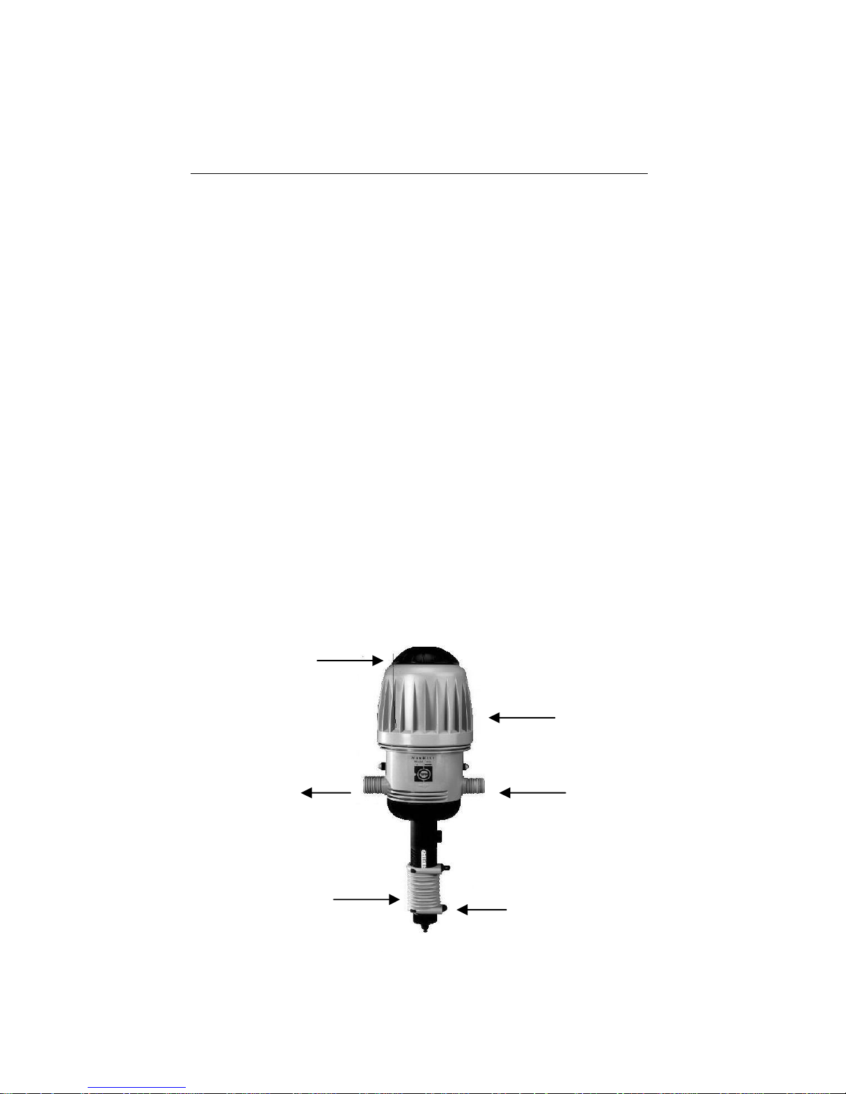
Water engine
Water inlet
A
dditive suction tube
Suction unit with adjustable
proportional dosing
Water outlet
A
ir release valve
User Manual
The MixRite is powered by water flow, with minimal loss of
pressure. The water engine powers the proportioning unit. No
external power is required.
The proportioning unit injectors liquid additives in direct relation to
the amount of water that passes through the motor and injects the
additives into the water system.
The water engine action:
The suction and proportioning unit is built from a piston connected
to the water engine, from which it derives its movement. The
piston moves within a cylinder with a non-return valve. The
movement of the piston within the cylinder causes the water to be
injectored and the required liquid additive to be drawn through a
pipe inserted into a container. It is possible to regulate the supply
ratio between the additive and the water passing through the
injector in models: 2502,2504,2510,12502,12504,12510.
In models 2500,2501,2506,12500,12501,12506 the dosing is
predetermined and can not be changed.
In models 2512,2514,12512,12514 The drawn additive is
transferred through a bypass tube directly into the main water line,
without contact with the water engine.
In models 2512IN, 2514IN, 12512IN, 12514IN The drawn additive
is transferred through a inlet bypass directly into the main water
line, without contact with the water engine.
3
Technical Data
MixRite operates in the following conditions:
From a minimum flow rate of 20 L/H (5.3 Gal/H) and up to 2,500
L/H (660 Gal/H)
Temperature not lower than 4˚C (39˚F) and not higher than
40˚C (104˚F)
Water pressure between 0.2 Bar to 8 Bar (2.9 to 120 PSI)
The additive may be added to the water flow according to the
required dosing percentage:
0.2% to 2% in models: 2502, 12502, 2512, 12512, 2502P,
2512IN, 12512IN.
0.4% to 4% in models: 2504, 12504, 2514, 12514, 2514IN,
12514IN.
3 % to 10% in models: 2510,12510
Fixed dosage 0.2 % in models: 2500, 12500
Fixed dosage 0.8 % in models: 2501, 12501
Fixed dosage 6 % in models: 2506, 12506
Water pressure loss:
Pressure loss in the lower flow rates 0.1 Bar and in the higher flow
rates up to 1 Bar.
Models with 0.2%-2%: from 0.1 Bar up to 1 Bar in proportion to
the water flow
Models with 0.4%-4%: from 0.2 Bar up to 1.2 Bar in proportion to
the water flow
Models with 3%-10%: from 0.5 Bar up to 1.8 Bar in proportion to
the water flow
The MixRite inlet and outlet are ¾" BSPT male thread.
The additive tank should be placed beneath the MixRite.
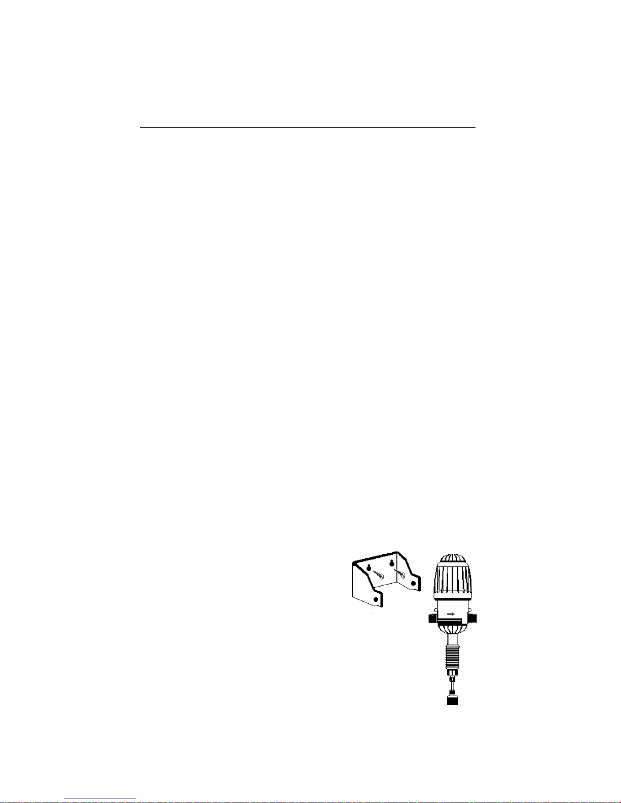
Mounting the MixRite
1. Prepare the MixRite site.
The MixRite intake and outlet must
reach the intake and outlet pipes.
The MixRite must be positioned above
the liquid additives container.
2. Screw the MixRite bracket onto a wall or
any stable vertical base.
3. Press the MixRite onto the bracket.
The nipples on the MixRite must click
into the holes in the side of bracket.
 Loading...