

Page 1
Prop
oUtional Injector
Bomba de dosificación proporcional
Pompe à Dosage Proportionnel
Pompa proporzionale
Manual del Usuario ● Manuel Utilisateur
● User Manuel ● Manuale d’Uso
Page 2
2
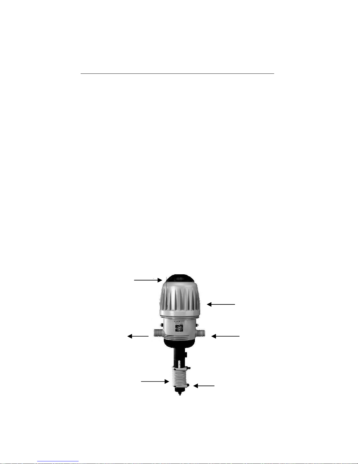
Water engine
Water inlet
A
dditive suction tube
Suction unit with adjustable
proportional dosing
Water outlet
A
ir release valve
User Manual
The MixRite is powered by water flow, with minimal loss of
pressure. The water engine powers the proportioning unit. No
external power is required.
The proportioning unit injectors liquid additives in direct relation to
the amount of water that passes through the motor and injects the
additives into the water system.
The water engine action:
The suction and proportioning unit is built from a piston connected
to the water engine, from which it derives its movement. The
piston moves within a cylinder with a non-return valve. The
movement of the piston within the cylinder causes the water to be
injectored and the required liquid additive to be drawn through a
pipe inserted into a container. It is possible to regulate the supply
ratio between the additive and the water passing through the
injector in models: 2502,2504,2510,12502,12504,12510.
In models 2500,2501,2506,12500,12501,12506 the dosing is
predetermined and can not be changed.
In models 2512,2514,12512,12514 The drawn additive is
transferred through a bypass tube directly into the main water line,
without contact with the water engine.
In models 2512IN, 2514IN, 12512IN, 12514IN The drawn additive
is transferred through a inlet bypass directly into the main water
line, without contact with the water engine.
Page 3
3
Technical Data
MixRite operates in the following conditions:
From a minimum flow rate of 20 L/H (5.3 Gal/H) and up to 2,500
L/H (660 Gal/H)
Temperature not lower than 4˚C (39˚F) and not higher than
40˚C (104˚F)
Water pressure between 0.2 Bar to 8 Bar (2.9 to 120 PSI)
The additive may be added to the water flow according to the
required dosing percentage:
0.2% to 2% in models: 2502, 12502, 2512, 12512, 2502P,
2512IN, 12512IN.
0.4% to 4% in models: 2504, 12504, 2514, 12514, 2514IN,
12514IN.
3 % to 10% in models: 2510,12510
Fixed dosage 0.2 % in models: 2500, 12500
Fixed dosage 0.8 % in models: 2501, 12501
Fixed dosage 6 % in models: 2506, 12506
Water pressure loss:
Pressure loss in the lower flow rates 0.1 Bar and in the higher flow
rates up to 1 Bar.
Models with 0.2%-2%: from 0.1 Bar up to 1 Bar in proportion to
the water flow
Models with 0.4%-4%: from 0.2 Bar up to 1.2 Bar in proportion to
the water flow
Models with 3%-10%: from 0.5 Bar up to 1.8 Bar in proportion to
the water flow
The MixRite inlet and outlet are ¾" BSPT male thread.
The additive tank should be placed beneath the MixRite.
Mounting the MixRite
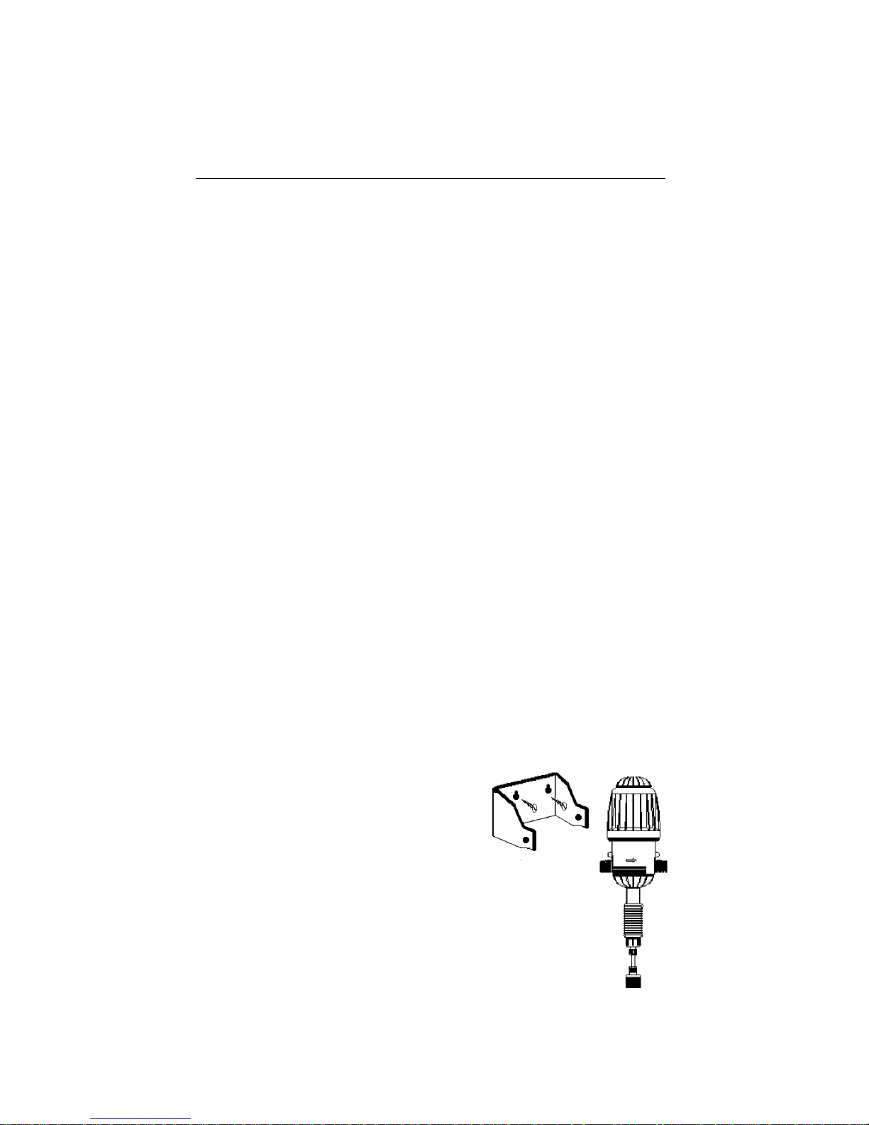
1. Prepare the MixRite site.
The MixRite intake and outlet must
reach the intake and outlet pipes.
The MixRite must be positioned above
the liquid additives container.
2. Screw the MixRite bracket onto a wall or
any stable vertical base.
3. Press the MixRite onto the bracket.
The nipples on the MixRite must click
into the holes in the side of bracket.
Page 4
4
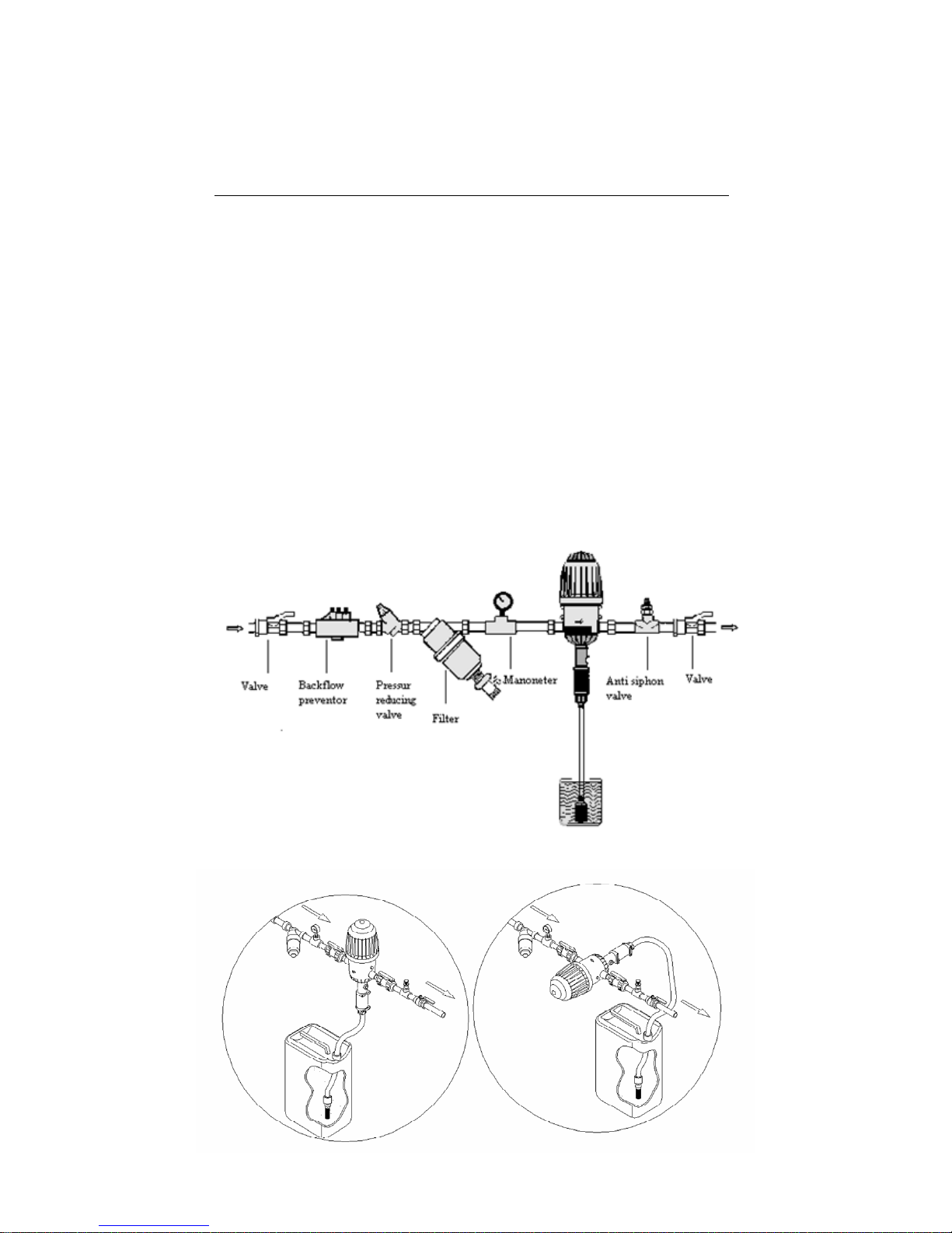
Installation of the MixRite
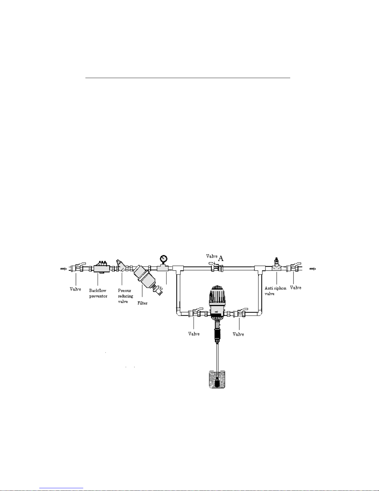
Installing the MixRite on a Direct Line (in line)
1. Install onto the water line using swivel connectors and ensure
that the water flows into the MixRite in the direction indicated by
the arrows printed on the MixRite.
2. Install a 50-75 mesh (250-300 micron) filter between the valve
and the injector intake.
3. Valves have to be installed at the water line entry and exit; in
order to stop the pump's action – you should close the Valve at
the entry point.
4. Position the drawing pipe into the additive container. Ensure that
the suction pipe filter is set several millimeters above the
container’s bottom. Check to ensure that the suction pipe is not
bent or folded.
Install the MixRite on a Direct Line (In Line)
3 2
Correct Installasation Incorrect Installasation
Page 5
5
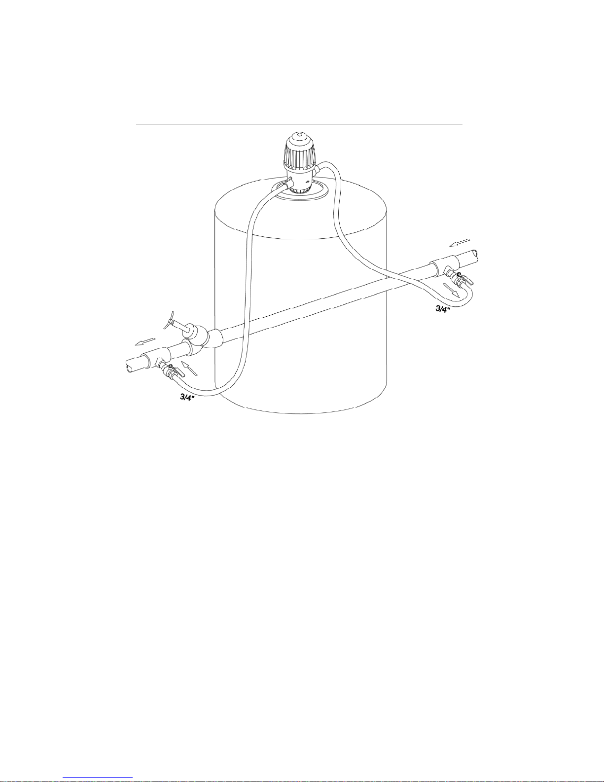
Installing the MixRite on a Bypass line (off line)
Where water is supplied at a higher flow rate, than the working
flow rate of the injector or where the injector isn’t needed for
continuous operation, the MixRite must be installed on bypass line.
The bypass provides the possibility to close the operation of the
injector while water continues to flow through the line.
1. Install onto the water line using swivel connectors and ensure
that the water flows into the MixRite in the direction indicated by
the arrows printed on the MixRite.
2. Install a 50-75 mesh (250-300 micron) filter between the valve
and the injector intake.
3. Valves have to be installed at the bypass entry and exit and on
the main water line.
4. Position the liquid additive container beneath the injector. Check
to ensure that the suction pipe is not bent or folded. Position the
drawing pipe into the additive container. Ensure that the suction
pipe filter is set several millimeters above the container’s bottom.
Install the MixRite on Bypass Line (Off Line)
Page 6
6
Adjusting the MixRite
Every stroke of the MixRite moves a predetermined volume of
water with a predetermined volume of liquid additive.
To adjust the volume of the liquid additive in models 2502, 2504,
2512, 2514, 12502, 12504, 12512, 12514, 2512IN, 2514IN,
12512IN, 12514IN:
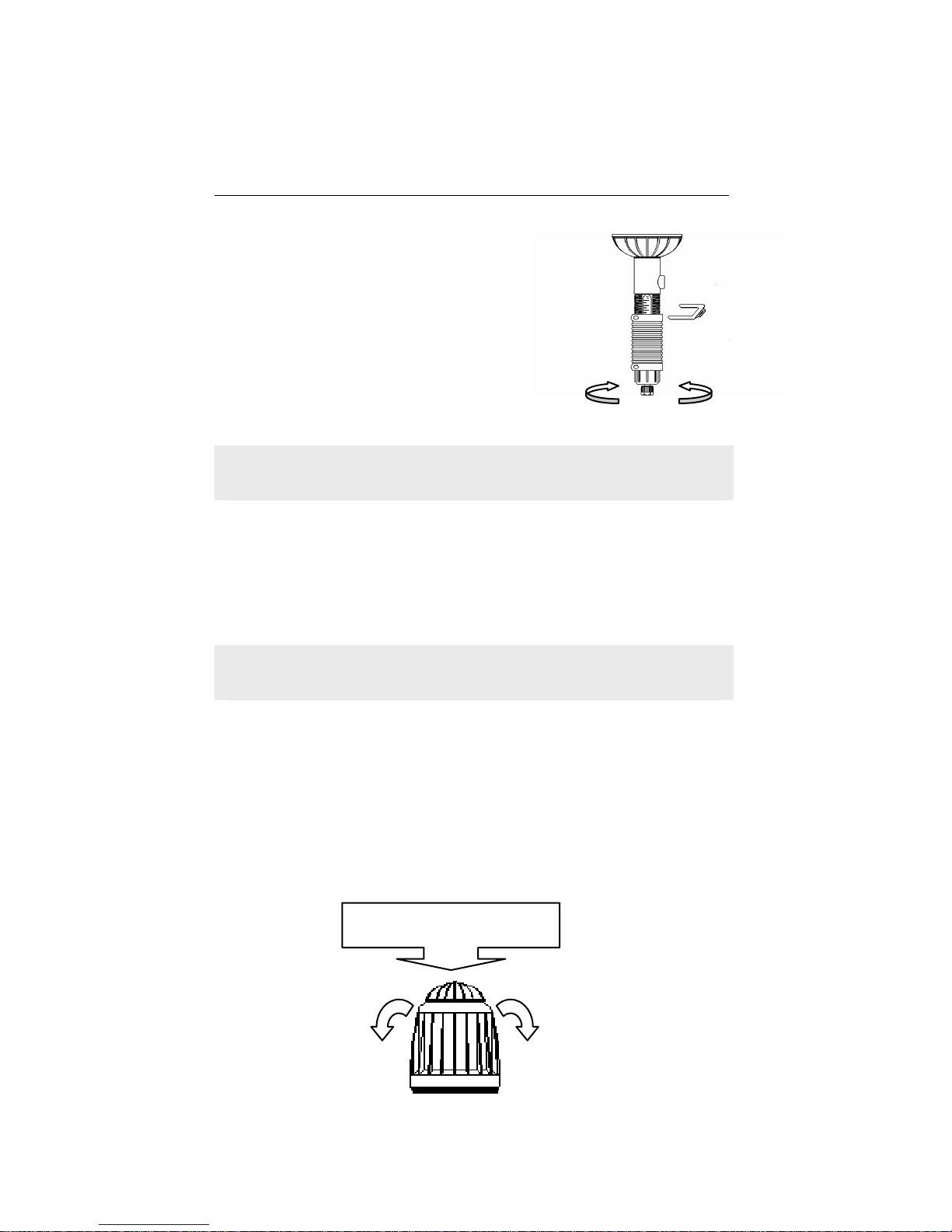
1. Remove the upper U–latch from the Proportioning Lock Nut.
2. Preset the amount of additives according to the Percentage to
Water Scale that is found on the proportioner.
• Turn the proportioning Adjuster counter clock-wise to increase
the amount of additives.
• Turn the Proportioning Adjuster clock-wise to decrease the
amount of additives.
The marking on the scale indicates the % of additive out of the
total water flowing through the injector.
3. Turn the proportioning Adjuster slightly, until the U-latch holes of
the Proportioning Lock Nut align with the notches in the
proportioner.
4. Push the U-latch into the U-latch holes of Proportioning Lock Nut
until it is firmly in place.
A
MixRite Bypass installation
2.5 (M/h)
including mobile fertilizer solution
tank
Chocking valve
Operating valve
Reservior Tank
Main Water Pipe
Page 7
7
To decrease To increase
U-latch
In models 2510, 12510 there is no Ulatch and the adjustment is done by
turning the adjustment sleeve to the
desired %.
In models 2500, 2501, 2506, 12500,
12501, 12506 there is no possibility to
adjust the dosing percentage, it is
predeterment by the injector model (see
page 3).
DO NOT REMOVE THE LOWER U-LATCH !!!
(For maintenance purpose only)
Rinsing and Cleaning the unit
After pumping
• Rinse the unit by pumping clean water from the additives
container.
• Wash the external surface of the unit with clean water.
Warning: During pumping, ensure that the additive
container is not completely empty.
Air-release Valve
In models: 2500, 2501, 2502, 2504, 2506, 2510, 2512, 2514,
2512IN, 2514IN.
After initial operation of the MixRite, apply pressure to the cap (the
air release valve) for several seconds to open valve that allows
trapped air to escape. This air release is accompanied by a slight
loss of water. Release the pressure on the cap to close the valve.
Air is released with a
small amount of
water
Press to release air
Page 8
8
Diagram 1 Diagram 2
On/Off System
In Models: 12500, 12501, 12502, 12504, 12506, 12510, 12512,
12514, 12512IN, 12514IN.
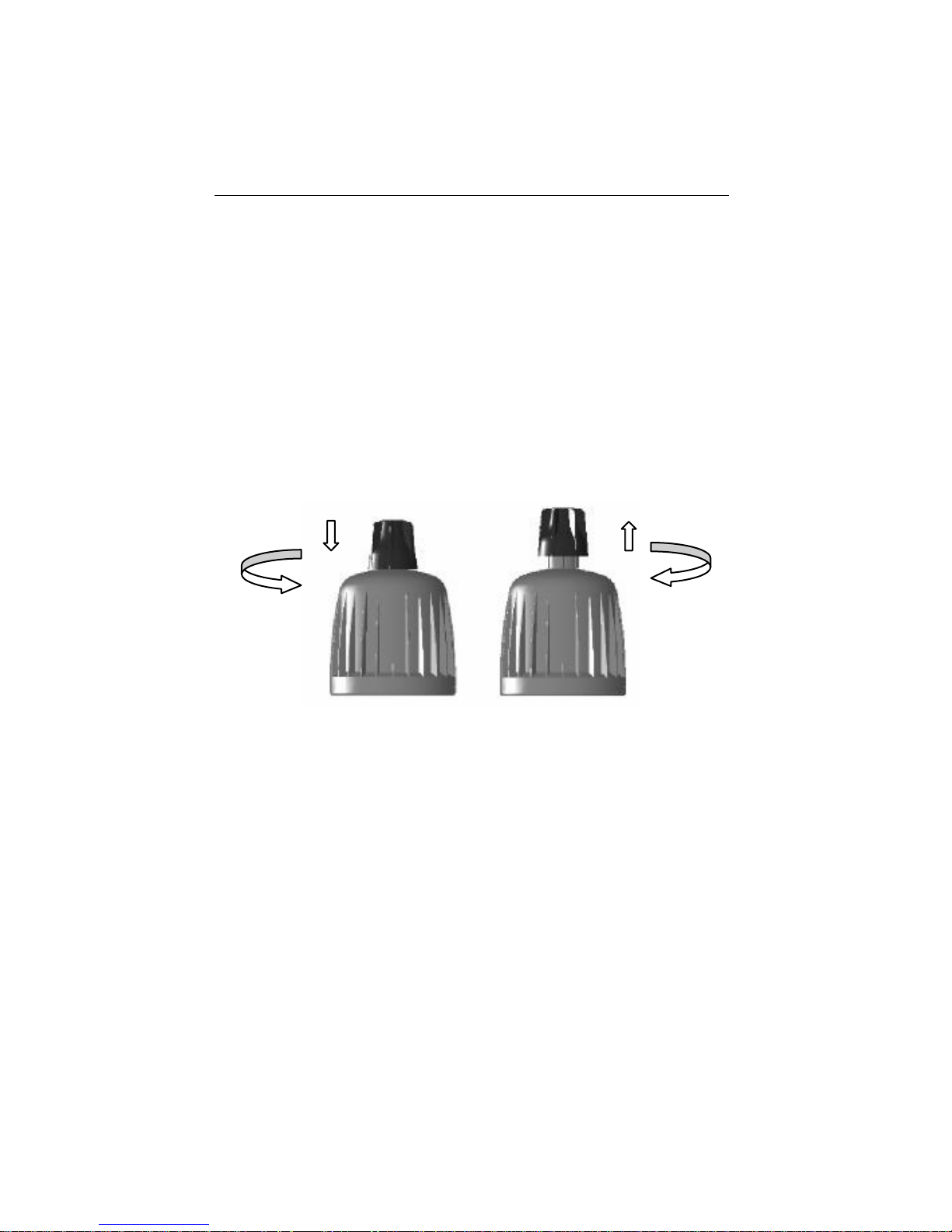
ON position – the Knob should be in its high position, the injector
is working & pumping.
OFF position – The knob is turned and pushed down to the cap,
the water flow the injector continuous without the pumping action.
To Turn the dosage unit off and allow the free flow of water
through the MixRite:
A: The handle must be turned and pushed in so that it is in the
close state.(see 1).
To Turn the dosage unit on and allow the pumping action MixRite:
B: The handle must be turned and pulled out so that it is in the
opened state. (see 2).
In injectors with On/Off knob there is no air-release valve.
It is highly recommended to use the On/Off knob when the additive
container is empty or there is no need at all in the additive but the
water flow should continue.
Page 9
9
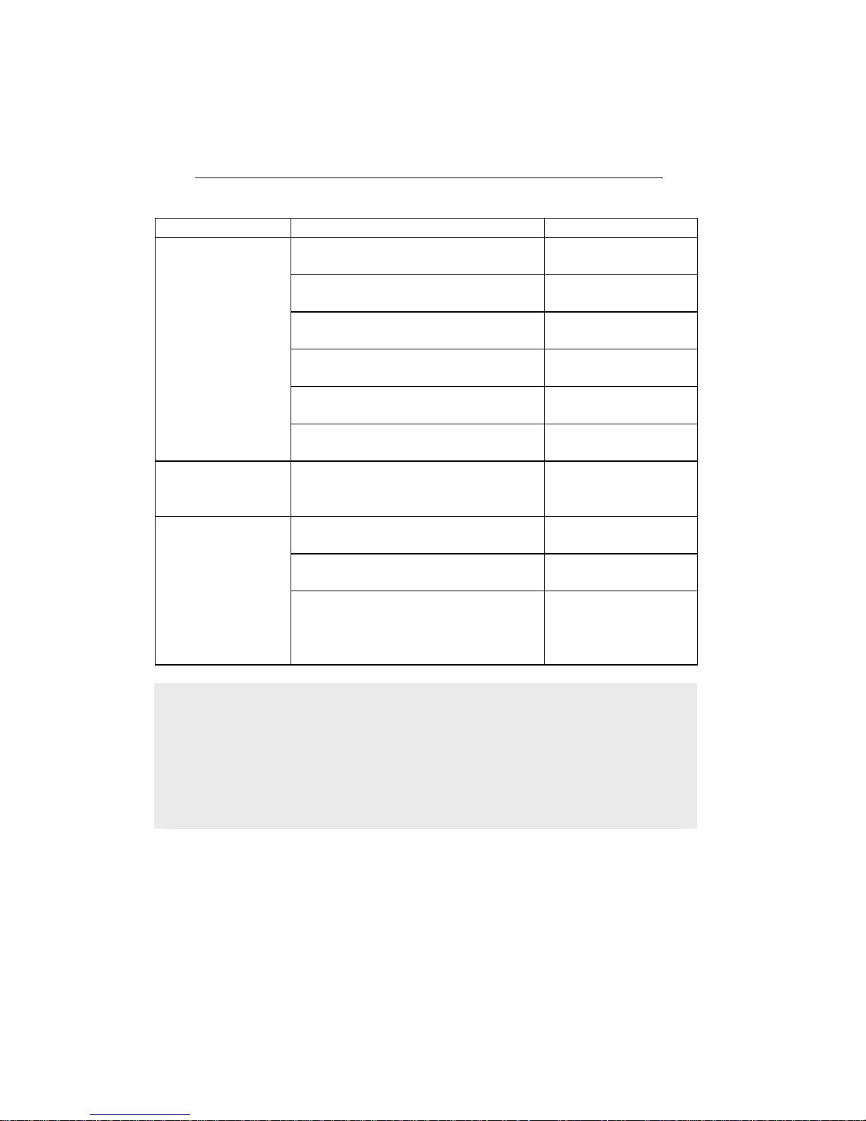
Troubleshooting
Problem Check Solution
Check that the intake and outlet
valves are open
Open the valve
Check that the water filter isn’t
clogged
Clean the filter
Check that water is flowing in the
line
Open main and
outlet valve
Check that springs are not broken
Open pump lid & remove piston
Change the broken
spring
Check that cylinder is not
scratched
Change cylinder
MixRite does not
operate
Check that piston seals are not
damaged
Change the seals
MixRite does not
draw
Dismantle the suction pump and
check the suction seal for damage
Change the suction
seal
Check if there is liquid in the
additive container
Add liquid to the
container
The MixRite
makes scratching
noises
Check if suction pipe is immersed
and not folded
Straighten or
change the pipe
Check suction filter to see if it is
blocked and if it is immersed in the
additive tank
Clean and rinse
suction filter, Fill
liquid into tank to
cover filter
Correct installation will prevent damages and malfunctions of the
MixRite
It is strongly recommended to install a back flow preventor before the injector
on the main water line.
A vacuum release unit should be installed at the outlet of the MixRite in order
to prevent undesired suction of additive when the water line is draining.
A master valve must be installed before the injector, to be opened
only for the operation of the injector to prevent water hammer
damage to the injector.
Page 10
10
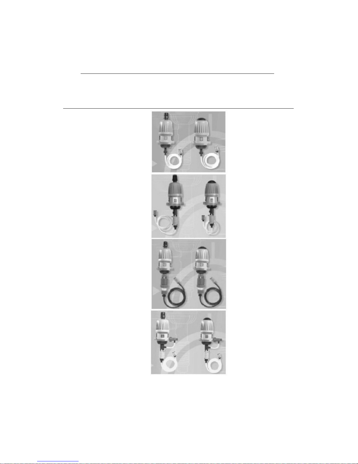
On/Off
models
Air release
valve models
MixRite 12500
MixRite 12501
MixRite 125HO
MixRite 2500
MixRite 2501
MixRite 12502
MixRite 12504
MixRite 12506
MixRite 2502P
(livestock feed)
MixRite 2502
MixRite 2504
MixRite 2506
MixRite 12510
MixRite 2510
MixRite 12512
MixRite 12514
MixRite 2512
MixRite 2514
 Loading...