

Page 1

TM
APRUS II
Operation Manual
Mixlinker Networks (Shenzhen) Inc.
Page 2

Warning
This equipment has been tested and found to comply with the limits for a Class B digital
device, pursuant to part 15 of the FCC Rules. These limits are designed to provide reasonable
protection against harmful interference in a residential installation. This equipment generates,
uses and can radiate radio frequency energy and, if not installed and used in accordance with
the instructions, may cause harmful interference to radio communications. However, there is
no guarantee that interference will not occur in a particular installation. If this equipment does
cause harmful interference to radio or television reception, which can be determined by
turning the equipment off and on, the user is encouraged to try to correct the interference by
one or more of the following measures:
1)Reorient or relocate the receiving antenna.
2)Increase the separation between the equipment and receiver.
3)Connect the equipment into an outlet on a circuit different from that to which the receiver is
connected.
4)Consult the dealer or an experienced radio/TV technician for help.
Caution: Any changes or modifications to this device not explicitly approved by manufacturer
could void your authority to operate this equipment.
This device complies with part 15 of the FCC Rules. Operation is subject to the following two
conditions: (1) This device may not cause harmful interference, and (2) this device must
accept any interference received, including interference that may cause undesired operation.
To comply with FCC RF exposure compliance requirements,this grant isapplicable to only
mobile configurations. The antennas used for this transmittermust be installed to provide a
separation distance of at least 20 cm from allpersons and must not be co-located or
operating in conjunction with any otherantenna or transmitter.
Page 3

Contents
I. Introduction ------------------------------------------------------------- 01
II. Nomenclature --------------------------------------------------------- 02
III. Packing List ------------------------------------------------------------ 03
IV. Specification ---------------------------------------------------------- 03
V. Interfaces ---------------------------------------------------------------- 04
VI. Indicators -------------------------------------------------------------- 08
VII. Connections ---------------------------------------------------------- 09
VIII. Installation ----------------------------------------------------------- 10
IX. FCC Warnning --------------------------------------------------------- 12
Page 4

I. Introduction
Welcome to use the Advanced Programmable Remote Utility
Server (APRUS II) of Mixlinker Network (Shenzhen) Inc. (herafter
referred to as Mixlinker).
APRUS is an advanced programmable Internet of Things
adaptor for industrial equipment developed by Mixlinker.
APRUS II is the second generation product of Mixlinker, and
will be referred to as APRUS II.
APRUS II is an intermediate adapter developed to address
theneeds of traditional equipment for IoT. Adaptors are used
to establish data communication with equipment (controller)
without making changes to equipment, by way of adapting, to
send the operation status and data to IoT platform, so as to
make the right judgement and take right action to reduce the
malfunction of equipment, lowing operation cost. This manual
briefly introduces APRUS II to customers, and provide
help to customers for using the product.
01
Page 5
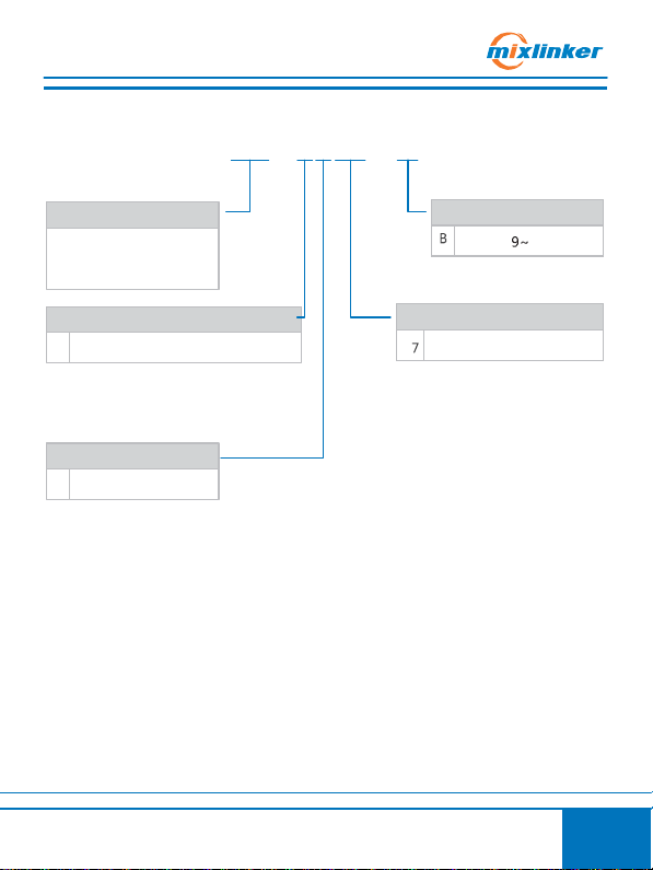
Product Info
Mixlinker
Adva
nce
d
Pro gr ammab
le Remote
Ut
ility Server (
APRUS II)
4
GPS
Modules
2
Module with GPS
A2 -
4207
- B
Communication Modules
2G Communication Module
Power Input
AC/DC 24V Input
Interfaces
0
CAN,RS485-1,RS485-2
II. No
menclature
02
Page 6

III. Packaging List
Item
Settings/Configurations
GPRS Antenna Interface
Standard SMA Interface
(Female Connector)
Wireless Network
GPRS 2G Network
(Not Supporting CDMA)
Input Voltage
AC/DC9~24V
Maximum Power Dissipation
3W
Average Power Dissipation
1W
Operating Temperature
-20° C to +45°C
Storage Temperature
-40° C to +100°C
Operating Humidity
45%-80%
Storage Humidity
30%-90%
Weight
210g
Dimension
146*97*49mm
RS485 Interface
Isolated
USB Interface
Mini USB Female Connector
APRUS II (1) GPS Antenna (1) - optional
GSM Antenna (1)
Micro SIM Card (1)
IV. Specification
03
Page 7

V. Interfaces
No.
Symbol
Definition
1
GPS
GPS Antenna Interface
2
GSM
GSM Antenna Interface
3
ETH
Ethernet Interface (Optional)
No.
Symbol
Definition
1
EXT
Extended Interface
APRUS II (Interfaces on Top)
APRUS II (Interface on Left Side)
GPS
1 2
1
ETH
GSM
3
04
Page 8

V. Interfaces
No.
Symbol
Definition
1
SIM
Micro SIM Card Slot
2 USB Interface
SIM
APRUS II (Interfaces on Right Side
APRUS II, when using Micro SIM
card, please insert the card“chip
down and notched edge facing
outward”
1
2
05
Page 9

V. Interfaces
No.
Item
Indicator
1
CAN-L
CAN-L
2
CAN-H
CAN-H
3
TX/A-1
RS232_TX1/RS485_A1
4
RX/B-1
RS232_RX1/RS485_B1
5
GND
Shared Ground
6
TX/A-2
RS485_A2 7 RX/B-2
RS485_B2 8 GND
Shared Ground
9
SGND
Shell Ground
10
POW +
Polarity - Positive
11
POW -
Polarity - Negative
CAN-L
CAN-H
TX/A-1
RX/B-1
GND
TX/A-2
RX/B-2
GND
SGND
POW +
POW -
APRUS II (Interfaces on the Bottom)
Note:
When choosing adapters of
one RS485 and one RS232, the
default for 3 and 4 is RS232,
and 6 and 7 is RS485
1 3 5 7 9 11
4
2
6 8 10
06
Page 10

V. Interfaces
No.
Item
Indicator
1
GSM
GSM Indicator Light
2
SVR
SVR Indicator Light
3
GPS
GPS Indicator Light
4
PWR
Power Indicator Light
5
RST
Reset Button
6
SOS
SOS Button
Note:
Press SOS to trigger a “s ho rt press e ven t” . Press and hold for 3 seconds to
trigger a “lo ng press ev en t” . Event will be handled by FIDIS, and may be
customized according to customers'needs.
APRUS II (F ront)
1
GSM SVR GPS PWR
2 3
5 6
RST
4
SOS
07
Page 11

VI. Indicators
Status
Indicator
Normal
Abnormal
1
GSM Status
Indicato r
1. Upon successful logon of SIM card,
indicator shall be on at the interval
of 3000ms, for 64ms each time.
2. Upon the connection of GPRS and
module is working normally,
indicator will be on at the interval
of 300ms, for 64ms each time.
1. When SIM card is not registered
online, indicator shall be on at the
interval of 800ms, for 64ms each
time.
2. When module is not powered on,
indicator shall be off.
2
SVR Status
Indicato r
1. When GARDS is correctly
connected, indicator shall be
on at the interval of 2s, for 60ms
each time.
1. When there is no signal for SIM card,
or not connected to antenna,
indicator shall flash three times every
2s, for 60ms each flashing.
2. Failure of SIM card registration with
vendor, indicator shall flash three
times every 2s, for 60ms each flashing.
3. When SIM card is not activated,
indicator shall flash three times every
2s, for 60ms each flashing.
4. When SIM card is not inserted
securely, or the slot on adaptor
becomes loose, or slot power source
is not compatible with SIM card,
indicator shall flash two times every
2s, for 60ms each flashing.
5. When adaptor is not connected to
server, indicator shall flash four times
every 2s, for 60ms each flashing.
3
GPS Status
Indicato r
1. When GPS signal is normal, indicator
shall be on two times every 2s, for
60ms each time.
1. When GPS signal is not normal,
indicator shall be off.
4
Power Status
Indicato r
1. When power is connected normally,
indicator will be on constantly.
2. When MCU is being upgraded,
indicator shall flash quickly at the
interval of 2s.
1. When power is not connected
normally, indicator will be off.
Note: During ele ct rical initi alization and s elf-testing on adapto rs , the
SVR , GPS and P WR indica to rs will simultaneously be on for 500ms and
off for 500ms.
08
Page 12

VII. Connections
GPS Antenna Interface
GSM Antenna Interface
Ethernet Interface (Optional)
ETH
GPS GSM
CAN Interfac
CAN Interfac
CAN-L
CAN-H
RS232 Interfac
Rs232 Interfac
RX/B-1
TX/A-1
RS485 Interfac
PLC
GND
TX/A-2
RS485 Interfac
RX/B-2
GND
Power Interface Power Interface
SGND
POW +
POW -
Note:
1.This wiring diagram dem on strates an adaptor
with a grouping of RS 485 and RS23 2. For
adapt ors w ith two groups of RS485, ple ase
refer to the abov e diagram for the wirin g of
RS485. Ple ase follow the correct wirin g.
Otherwi se data wil l not be co lle cted from
equip ment.
2.Please connect the
ant ennas of GPS and
GSM correctly.
Otherwi se equi pm ent
shall not pick up signa l
and GPS will not locate
the posit io n.
CAN-L
CAN-H
TX/A-1
RX/B-1
GND
TX/A-2
RX/B-2
GND
SGND
POW +
POW -
APRUS II
CAN-L
CAN-H
TX/A-1
RX/B-1
GND
TX/A-2
RX/B-2
GND
SGND
POW +
POW -
09
Page 13

VIII. Installation
There are two methods for APRUS II installation: 1. With screws,
screw size: M4.5, as shown below:
10
Page 14

VIII. Installation
35mm
2. Installation with rails, the size of rail: 35mm, as shown below:
Insta ll stop per
Rail
Step 1:
Raise the stopper
on the adaptor.
Note:
1. For the safe ty of you
and the equipment
and adapto r, ple as e
power off the
equip ment prior to
perfo rm ing the
installation.
2. Prior to in st allatio n,
ple ase insert SIM
card into s lot and
complete all the
wiring correctly on
adaptor.
Step 2:
Insta ll the adaptor onto
the rail. (Plea se se cure
the bo ttom rail groo ve
onto the rail bottom first.)
Step 3:
Push down the stopper.
11
Page 15

Mixlinker Networks (Shenzhen) Inc.
:3/F Spring Tower, Meisheng Creative
Valley, 10 Longchang Rd. Shenzhen
:0755-23740592
:www.mixlinker.com
V1.0
 Loading...