

Page 1

MIXING PUMP MIXER PLUS
MANUAL INSTRUCTIONS
ORIGINAL INSTRUCTIONS
Revision n…… of ……
MIXER TECHNOLOGY srl
Via dei Carabinieri, 45, 36040
Torri di Quartesolo (VI) Italy
www.mixersrl.com
Page 2

GENERAL INDEX
MIXING PUMP MIXER PLUS ............................................................................................................ 1
MANUAL INSTRUCTIONS ............................................................................................................... 1
GENERAL INDEX ........................................................................................................................... 2
CE MARKING ................................................................................................................................ 3
FINAL TESTING AND COMMISSIONING ............................................................................................ 3
RESERVED RIGHTS ....................................................................................................................... 3
DECLARATION OF CONFORMITY ..................................................................................................... 4
TECHNICAL DATA ......................................................................................................................... 4
DIMENSIONS OF THE MACHINE ...................................................................................................... 5
PARTS LIST .................................................................................................................................. 7
PACKAGING ................................................................................................................................. 8
UNPACKING ................................................................................................................................. 9
USE DESTINATION ........................................................................................................................ 9
DISPOSAL .................................................................................................................................... 9
MACHINE TRANSPORT ................................................................................................................. 10
SAFETY INSTRUCTIONS ............................................................................................................... 11
RESIDUAL RISKS ........................................................................................................................ 12
FORESEEABLE INCORRECT USE .................................................................................................... 12
ASSEMBLING OF ROTOR AND MIXER............................................................................................. 13
WATER CONNECTION .................................................................................................................. 15
CONNECTION OF THE MATERIAL CONVEYING TUBE ........................................................................ 15
CONNECTION OF THE AIR TUBE TO THE COMPRESSOR ................................................................... 16
CONNECTION OF THE MATERIAL CONVEYING AND AIR TUBES TO THE SPRAYING NOZZLE .................. 16
ELECTRICAL CONNECTIONS ......................................................................................................... 17
CONTROL PANEL......................................................................................................................... 18
PLUS-MONO MODEL .................................................................................................................... 18
PLUS-TOP MODEL ....................................................................................................................... 18
PLUS STANDARD CONTROL PANEL ................................................................................................ 20
CHECKS BEFORE SWITCHING ON ................................................................................................. 22
MACHINE PREPARATION .............................................................................................................. 23
SPRAYING OF THE MATERIAL ....................................................................................................... 25
MACHINE SWITCHING OFF .......................................................................................................... 25
CLEANING OF CHAMBER MIXING .................................................................................................. 26
CLEANING OF THE HOPPER .......................................................................................................... 27
CLEANING OF THE SPRAYING NOZZLE AIR TUBE ............................................................................ 28
SWATER DRAINAGE DURING WINTER PERIOD ............................................................................... 28
RESEARCH OF MALFUNCTIONS ..................................................................................................... 29
ROUTINE MAINTENANCE ............................................................................................................. 31
REPLACEMENT OF THE ROTOR STATOR ......................................................................................... 32
WARRANTY ................................................................................................................................ 33
Manual instruction Mixer Plus Mixer Technology srl pag.2
Page 3
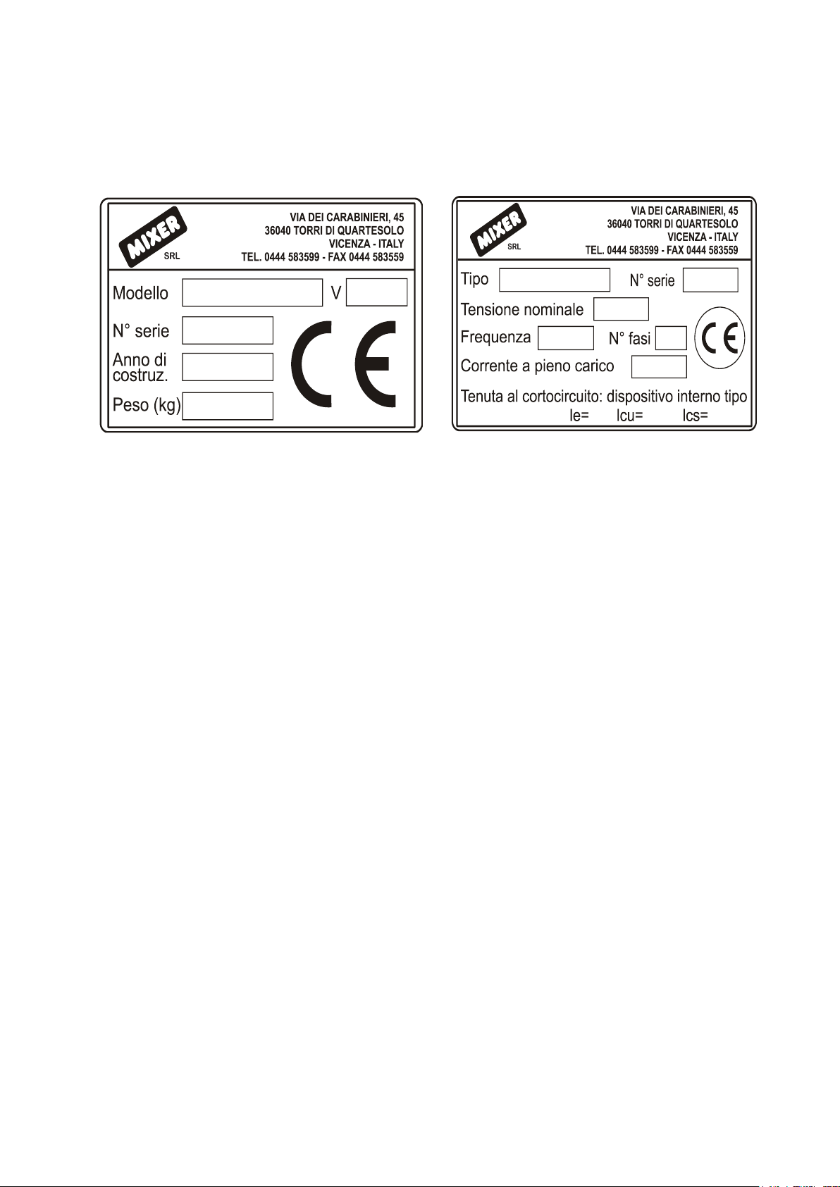
CE MARKING
FINAL TESTING AND COMMISSIONING
(by the Manufacturer or the authorized Dealer)
The machine is already tested at the Manufacturer's premises.
The commissioning of the machine at the client is carried out by Manufacturer
or the Authorized Dealer.
At the end of the testing, the Manufacturer or Authorized Dealer fills in the
testing and commissioning certificate on page 2, which is signed by the testing
technician, the operator in charge (or any other authorized operator), and by
the safety manager, who shall certify the positive result of the same.
RESERVED RIGHTS
The contents on this manual can’t be reproduced and disclosed (totally or
partially) without written authorization of the Manufacturer.
Manual instruction Mixer Plus Mixer Technology srl pag.3
Page 4

MIXER TECHNOLOGY srl
Via dei Carabinieri, 45, 36040
Torri di Quartesolo (VI) Italy
www.mixersrl.com
DECLARATION OF CONFORMITY
In accordance with the Directive 2006/42/CE – D.Lgs 17/2010
DECLARES UNDER ITS OWN RESPONSIBILITY THAT THE MACHINE
Type ……………………………………………………………………
Serial number /Model ……………………………………………………………………
Year of construction ……………………………………………………………………
It’s conform to the following European Directives and the following modifications:
Directive 2006/42/CE, recognize in Italy with D.Lgs. 17/2010 (Machinery
Directive)
Directive 2014/35/CE (Low Voltage Directive) recognize in Italy with D.Lgs. 19
Maggio 2016, n. 86
Directive 2014//30/CE (Electromagnetic Compatibility)
And the following standards:
EN 60204-1:2016 Safety standard of the electrical equipment of machines
EN 12100-1 and 2 Machinery Safety – Essential concepts, main design
principles
The technical dossier is keeped by Manufacturer.
……………………. date …………………... Signed
TECHNICAL DATA
Manual instruction Mixer Plus Mixer Technology srl pag.4
Page 5

The models available of the machine: MIXING PUMP MIXER PLUS
MODELS
POWER SUPPLY
POWER
WATER SUPPLY
PLUS MONO 2,2 KW
2 x 230 Volt
3,7 kw
Water
PLUS MONO 3 KW
2 x 230 Volt
3,7 kw
Water
PLUS MONO
STANDARD
3 x 400 Volt
7,4 kw
Water
PLUS MONO TOP
3 x 400 Volt
7,4 kw
Water
PLUS MONO CD25
3 x 400 Volt o 2 x
230 Volt
3,7/7,4
kw
Water
MODEL
DIMENSIONS (cm)
WEIGHT
(without tubes)
PLUS MONO 2,2 KW
A=155 B=110 C=66
215 kg
PLUS MONO 3 KW
A=155 B=110 C=66
215 kg
PLUS STANDARD
A=155 B=110 C=72
240 kg
PLUS TOP
A=155 B=110 C=72
240 kg
PLUS CD25
A=155 B=110 C=72
240 kg
Operating temperature: minimum+5°C, maximum +35°C
Protection grade of switchboard: IP44
Water pump flow rate: 40 litres/min
Compressor air flow rate: 240 litres /min
Flow rate: 6-50 litres /min
Hopper capacity: 80 litres
Max. served distance: 40 meters
Weighted noise pressure level “A”: 92 dB
If the withdraw water is from a deposit, tub or well, it’s require insert a cleaner upline
of the machine.
Accessories upon request: Fairing for feeding from silo
DIMENSIONS OF THE MACHINE
Manual instruction Mixer Plus Mixer Technology srl pag.5
A= Height B= Width C= Depth
Page 6
1 2 3
4
5 6 7
8
13
9
10
11
12
14
15
16
1718202122
232425
14
1
10 9 26
3
25
27
19
Manual instruction Mixer Plus Mixer Technology srl pag.6
Page 7

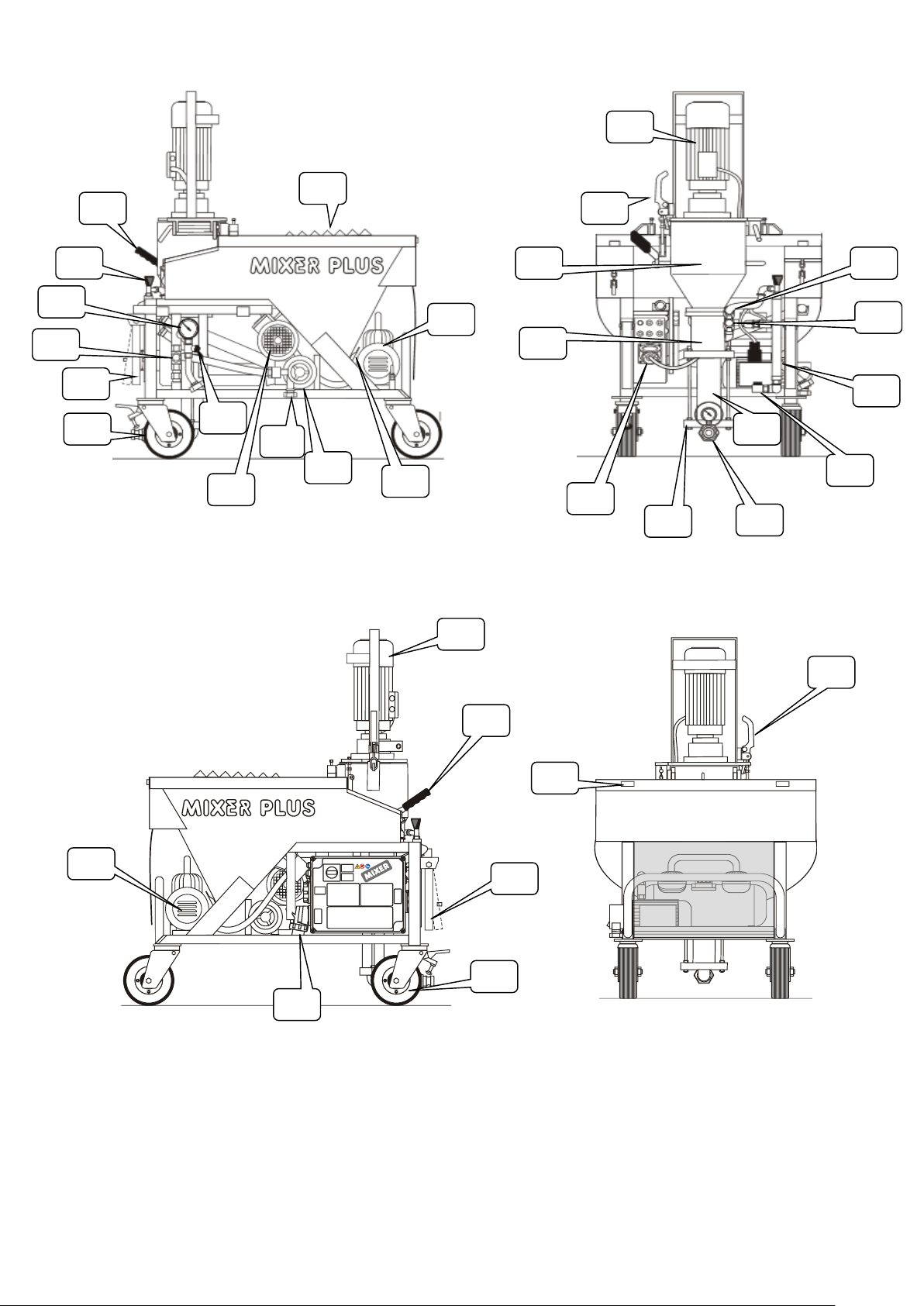
PARTS LIST
1. Mixing chamber locking lever
2. Hopper protection grating with bag cutting blade
3. Compressor
4. Hopper discharge door
5. Water pump
6. Water inlet
7. Cell wheel gearmotor
8. Service tap
9. Pivoting wheels
10. Lifting handles
11. Water pressure reduction unit
12. Water line pressure gauge
13. Water adjustment valve
14. Mixing assembly gearmotor
15. Water inlet in the mixing chamber (light products)
16. Water inlet in the mixing chamber (all products, except for light ones)
17. Flow meter
18. Water drain tap
19. Stator (plenum chamber)
20. Material output connection
21. Material output pressure gauge
22. Gearmotor power supply outlet (only mod. Plus Mono)
23. Trunket
24. Mixing chamber
25. Gearmotor assembly locking device
26. Main power supply plug
27. Rear connection points for the fairing
Manual instruction Mixer Plus Mixer Technology srl pag.7
Page 8

PACKAGING
Usually the machine is packaged by the Manufacturer on wooden pallet, fastened with
straps and wrapped with a film.
List of supplied loose components:
No. 1 Mixer;
No. 1 Rotor;
No. 1 "T" wrench;
No. 1 Spraying nozzle;
No. 1 Material conveying tube (ø est. 39 mm - L= 15 m);
No. 1 Air tube (ø est. 19 mm - L= 16 m);
No. 1 Water tube (ø est. 26 mm - L= 40 m);
No. 1 Power supply cable with outlet, without plug (L= 50 m).
Components positioned in the tool carrying box
No. 1 Instructions for use and maintenance;
No. 1 "Anti-grip" liquid bottle with sprayer;
No. 1 Cleaning device;
No. 1 Spraying nozzle air tube cleaning tool;
No. 1 Screwdriver;
No. 1 Fixed wrench (2 sizes 24 - 36 mm);
No. 1 Fixed wrench (3 sizes 30 - 13 - 10 mm);
No. 2 Diffuser rubber spare (nozzle) parts for spraying nozzle;
No. 2 Small foam rubber balls to clean the material conveying tube;
No. 2 Water tube fittings;
No. 2 Water tube clamps;
No. 2 Fittings (reduction units) for water inlet (1" - 3/4");
No. 1 Fast connection for cleaning the material transport tube;
No. 1 Cleaning device rod.
Manual instruction Mixer Plus Mixer Technology srl pag.8
Page 9

UNPACKING
1) Remove the protective film;
2) With a proper tool, cut the straps paying attention not to be hit by the same due to
their elasticity;
3) Release the brake of the pivoting wheel;
4) With the help of a second operator, let the machine carefully get off the pallet
lifting it using the proper handles positioned on the machine sides;
5) Lock the brake of the pivoting wheel.
USE DESTINATION
The use destination of the machine is to use in building sector for the Mixing and
spraying of pre-mixed products having a max. granulometry of 5 mm, suitable for
plastering.
Can be used for the processing: Pre-mixed plasters, dry or in silo, having as base:
plaster, plaster lime, cement lime, finishing plasters, stoppers, coloured plasters,
gluing agents in general, foundation for floors and mortars.
Any other different use is potentially inappropriate.
DISPOSAL
At the disposal time of the machine, compulsorily observe the provisions of the
regulations in force.
Separate the parts making up the machine according to the different construction
materials (plastic, copper, iron, etc...).
Lubricant liquids and any other fluids shall absolutely not be dispersed in the
environment.
These products, deemed polluting and hazardous, shall be compulsory disposed
entrusting companies authorized and specialized for the different types of product.
Manual instruction Mixer Plus Mixer Technology srl pag.9
Page 10
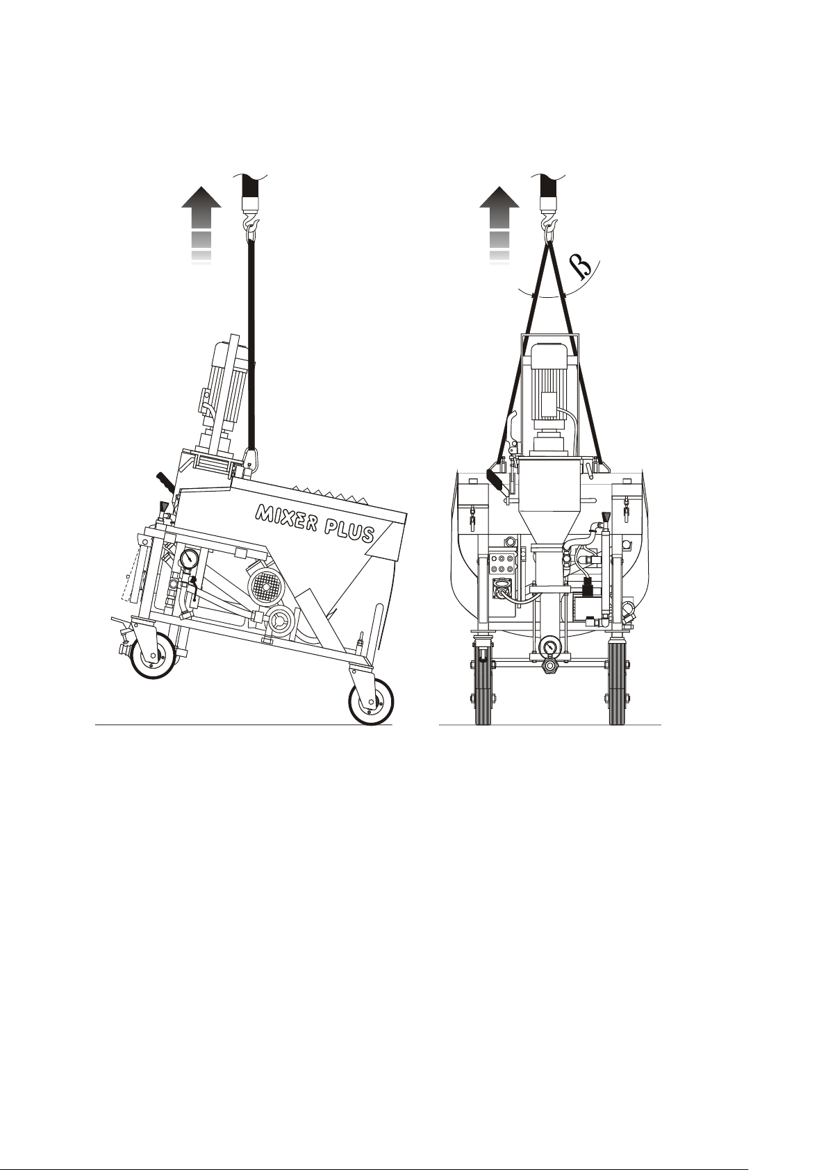
MACHINE TRANSPORT
In the drawing are visible the coupling points for the transport and handling of the
machine.
Manual instruction Mixer Plus Mixer Technology srl pag.10
Page 11

SAFETY INSTRUCTIONS
1. The machine use is only reserved to qualified and trained staff in according to
the safety provision law.
2. Always remove the voltage, turning off master switch, before to do any
operation on the machine.
3. The master switch has also the stop emergency function in case of necessity.
4. Conform to use destination of the machine described in the in the specific
chapter.
5. The disconnection of the material conveying tube, it is compulsory to done only
with pressure at zero of pressure gauge.
6. Consult the instructions of pre-mixed products, before to use the machine
7. The machine is not suitable to use in environments with potentially explosive
atmospheres (Atex)
8. Only one operator at time on the machine
9. The machine has not been conceived for to transport and/or lift persons and
things.
10. Pay attention to transport the machine on slopes, danger to be run over
11. It is absolutely forbidden to tamper, disconnect and/or remove any safety
device existing in the machine.
12. Lock the brake of the pivoting wheel, just finished the movement.
13. For the safe use of the machine are recommended the following personal
protective equipment: safety footwear, protective gloves from chemicals,
goggles or face shield, earmuff.
14. Don’t introduce objects thought the hopper protection grating. Don’t use the
machine with the open grating.
15. It is absolutely forbidden to tamper the calibration of pressure reduction valve.
16. Don’t step or pull tubes and the electrical connections.
Manual instruction Mixer Plus Mixer Technology srl pag.11
Page 12
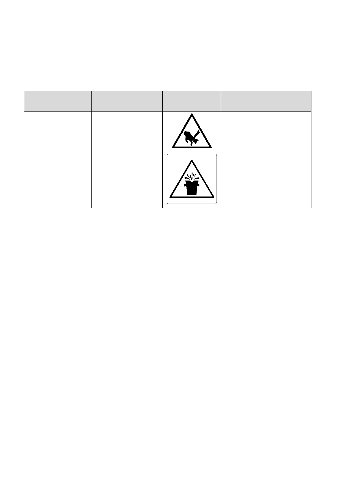
RESIDUAL RISKS
ZONE
RESIDUAL
RISKS
DANGER
PREVENTIVE
MEASURES
Hopper
protection
grating
Cutting hazard in
case of contact
with the bag
cutting blade
Education, training.
Material
conveying tube
hazard to be hit
by the ejection of
material subject
to pressure.
Education, training.
The tubes
disconnection only in
the absence of pressure
indicated in gauge.
The machine was designed and produced to compliance with current legislation at state
of art.
However the machine presents residual risks, risks that can’t be eliminated at the
source and involving a particular training and the operator’s attention.
FORESEEABLE INCORRECT USE
Don’t use different products from the Antigrip, supplied, for danger of malfunctions of
the machine.
Don’t throw foreign body in hopper (gravel, stones, etc….) for danger of machine
breakdown and dangerous projection.
Manual instruction Mixer Plus Mixer Technology srl pag.12
Page 13
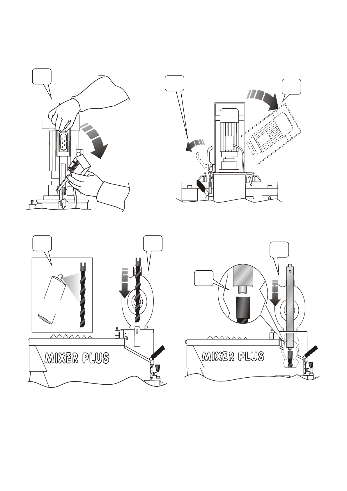
ASSEMBLING OF ROTOR AND MIXER
A B C D E
F
G
Antigrip
Carry out the operations by following the letters in succession.
Manual instruction Mixer Plus Mixer Technology srl pag.13
Page 14
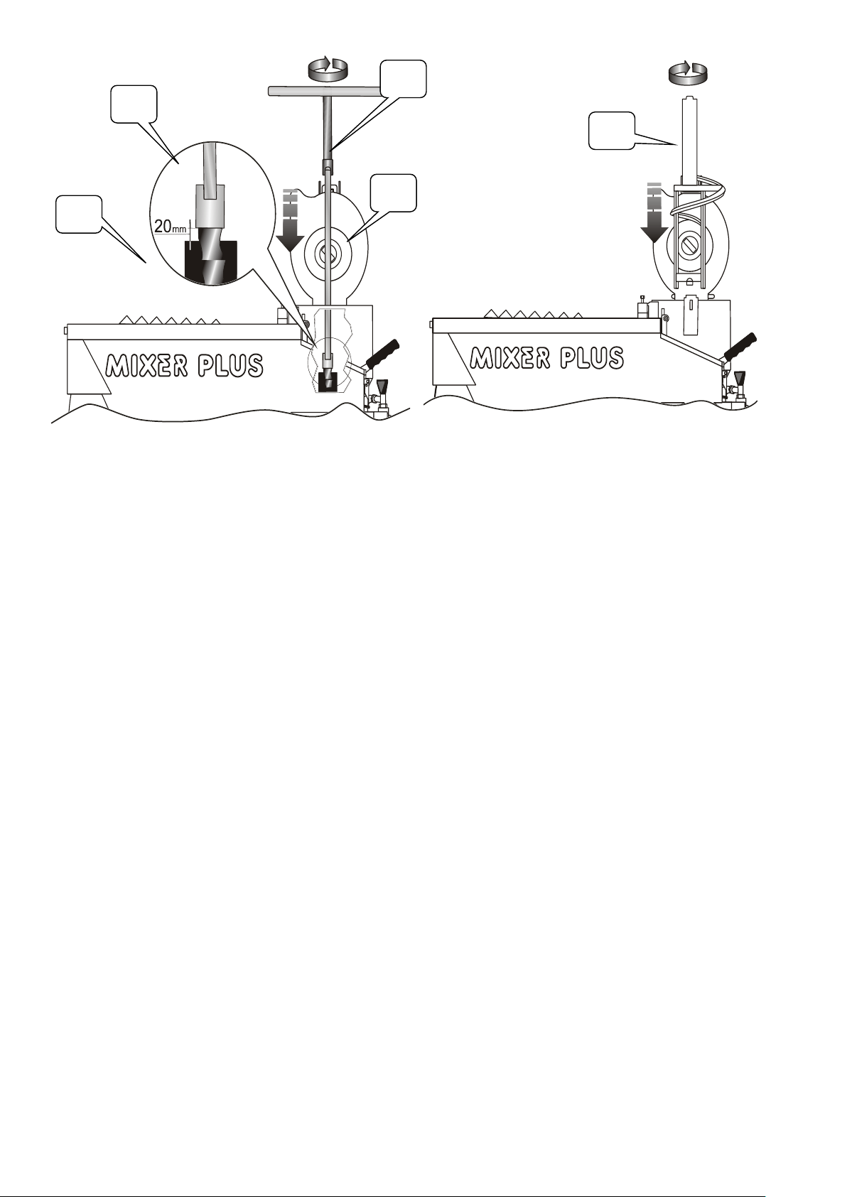
H
I L M
N
Manual instruction Mixer Plus Mixer Technology srl pag.14
Page 15
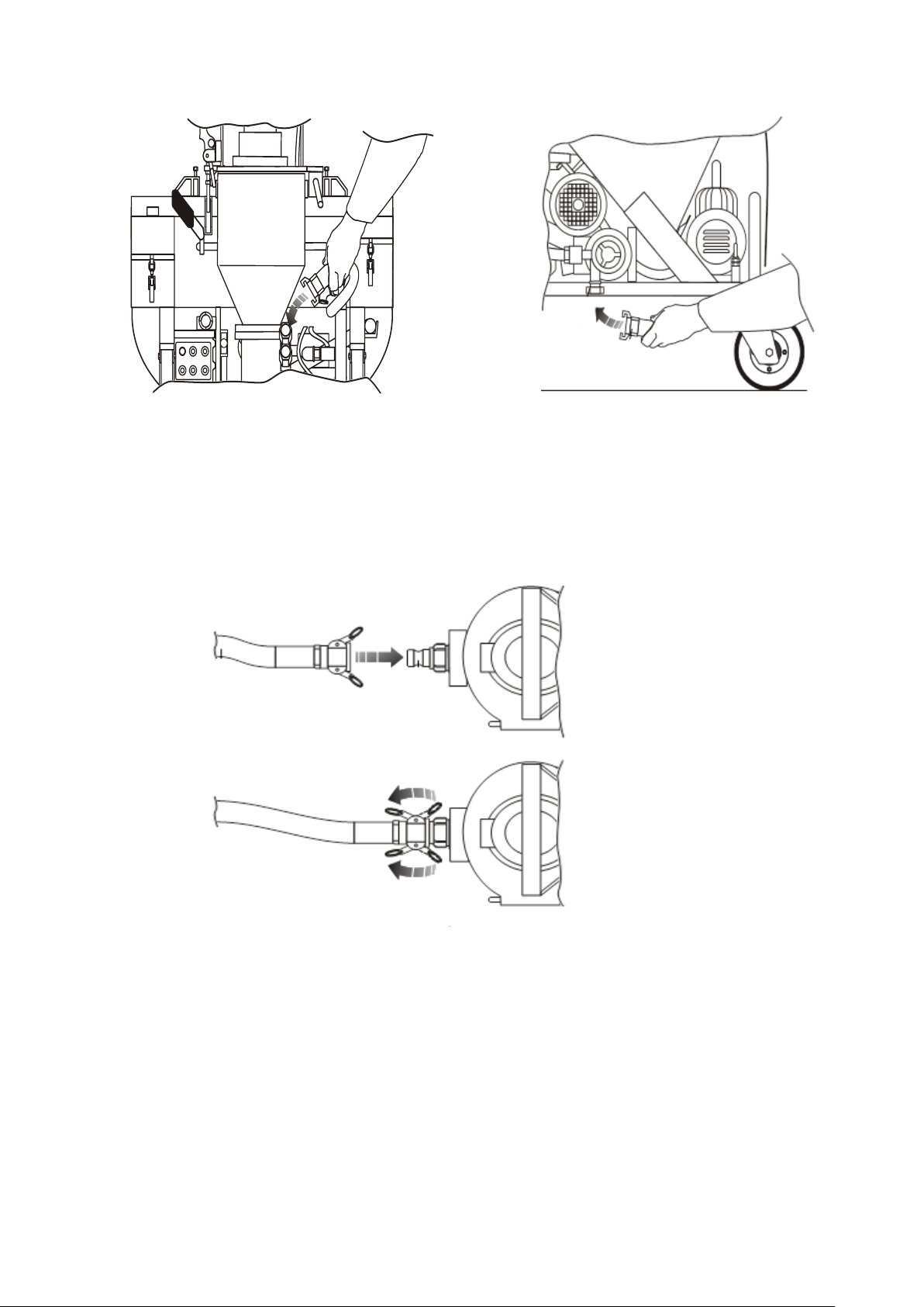
WATER CONNECTION
CONNECTION OF THE MATERIAL CONVEYING TUBE
Attention:
Performing the disconnection only in the absence of pressure indicated in gauge.
Manual instruction Mixer Plus Mixer Technology srl pag.15
Page 16
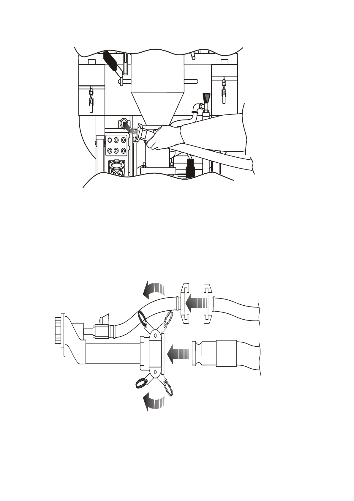
CONNECTION OF THE AIR TUBE TO THE COMPRESSOR
1
2
CONNECTION OF THE MATERIAL CONVEYING AND AIR TUBES
TO THE SPRAYING NOZZLE
Manual instruction Mixer Plus Mixer Technology srl pag.16
Page 17
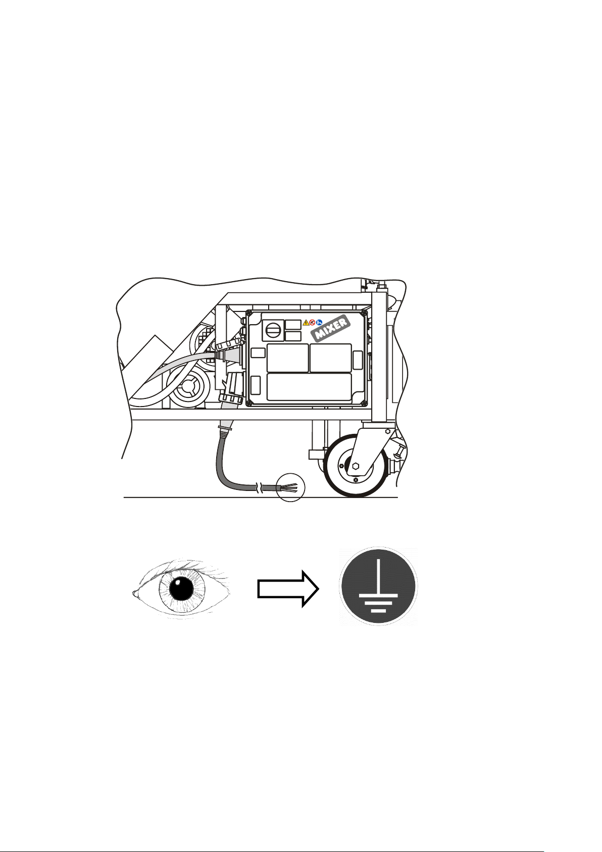
ELECTRICAL CONNECTIONS
Verify that the starter electrical connections, is complies to to the legislation in
force in electrical connections safety area (marking CE).
The machine is not suitable to connect to power supply outlets of house systems.
Verify to provide voltage and power appropriate to the machine.
Verify that thermal magnetic circuit breaker protection and residual current
protection (life saver) is installed.
All the electrical connections (plugs - sockets) must be CEE industrial type with
protection degree IP67.
The use of extension cords is admitted only if made in safety standards (cross-
section of conductors, insulation, earthing, etc..)
Manual instruction Mixer Plus Mixer Technology srl pag.17
Page 18
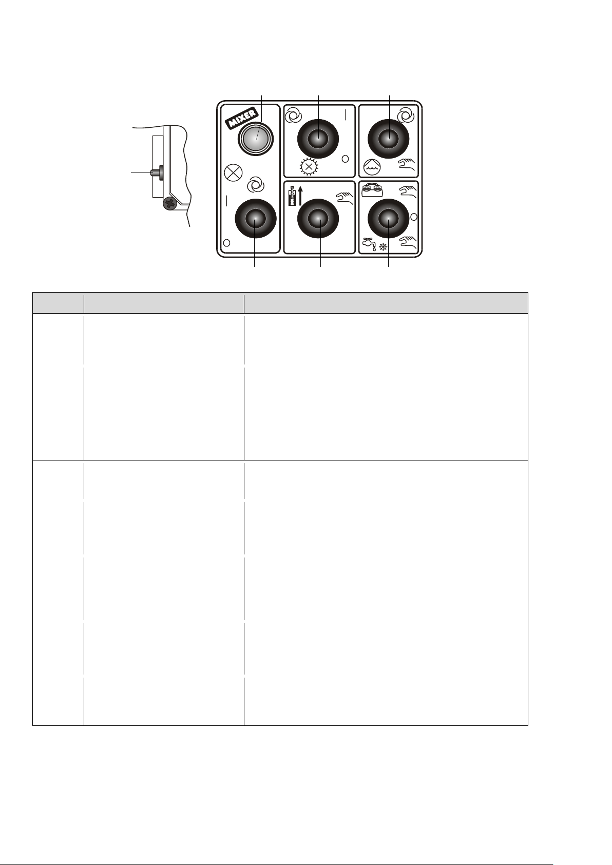
CONTROL PANEL
RIF
COMMAND
FUNCTION
1
Machine Run/Stop
I: automatic run;
Return: neutral position;
0: automatic stop.
2
Warning led state of
machine
Green fixed: stopped;
Red fixed: running;
Orange fixed: minimum voltage;
Green intermittent: lack of water;
Red intermittent: thermal protections
tripping.
3
Cell wheel motor
O: stopped;
I: running.
4
Water pump
UP: automatic run;
O: stopped;
DOWN: manual run.
5
Compressor and
winter drain
UP: run/stop compressor;
O: neutral position;
DOWN: winter drainage.
6
Mixer reverse run
UP: Reverses rotation direction of the
mixer;
O: neutral position.
7
Frequency selection
Left: 50 Hz electric frequency operation;
Centre: 40 Hz electric frequency operation;
Right: 45 Hz electric frequency operation.
3
6
5
4
2 1 7
PLUS-MONO MODEL
PLUS-TOP MODEL
Manual instruction Mixer Plus Mixer Technology srl pag.18
Page 19
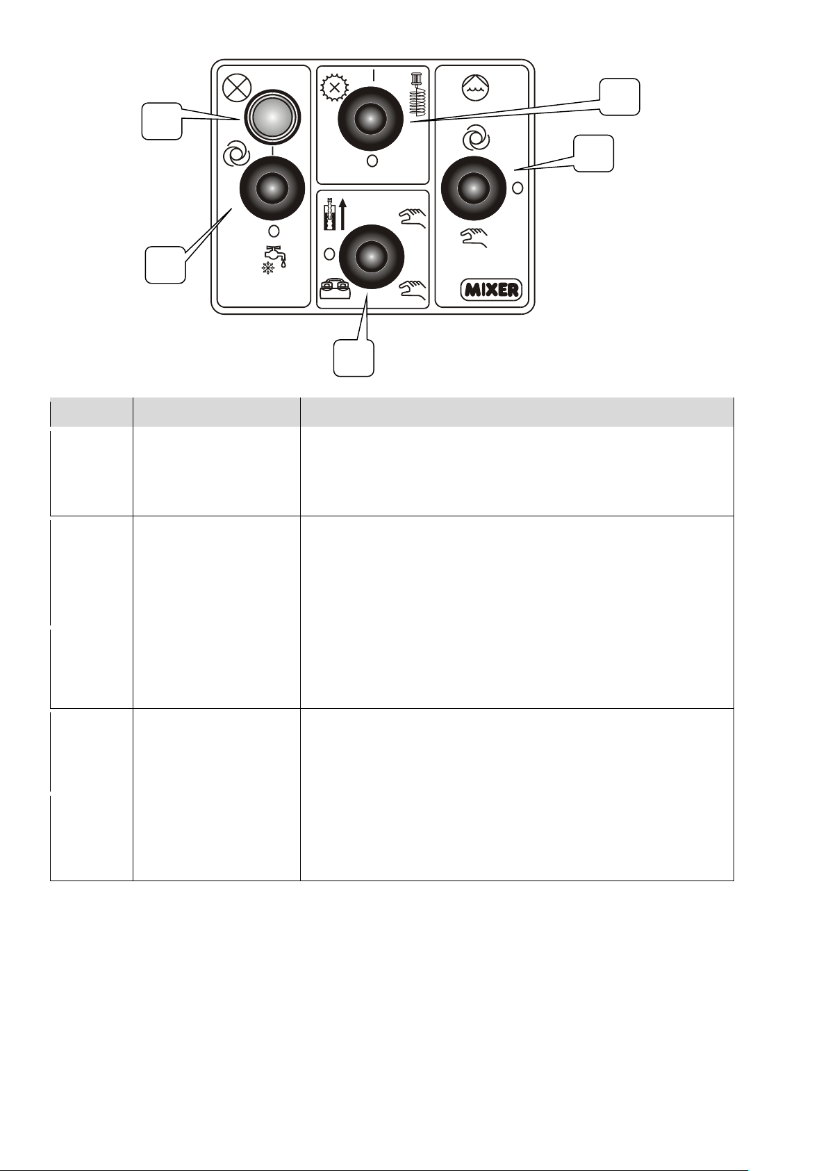
RIF.
COMMAND
FUNCTION
1
Machine Run/Stop
I: automatic run;
Return: neutral position;
0: automatic stop;
By hold the action “O” start the winter drainage.
2
Warning led state
of machine
Green fixed: stopped;
Red fixed: running;
Orange fixed: minimum voltage;
Green intermittent: lack of water;
Red intermittent: thermal protections tripping.
3
Cell wheel motor
O: stopped;
I: running.
4
Water pump
UP: automatic run;
O: stopped;
DOWN: manual run.
5
Mixer reverse run
and compressor
run
UP: By hold the action reverses rotation direction
of the mixer;
O: neutral position;
GIU’: stop the compressor.
1
5
4 3 2
Manual instruction Mixer Plus Mixer Technology srl pag.19
Page 20
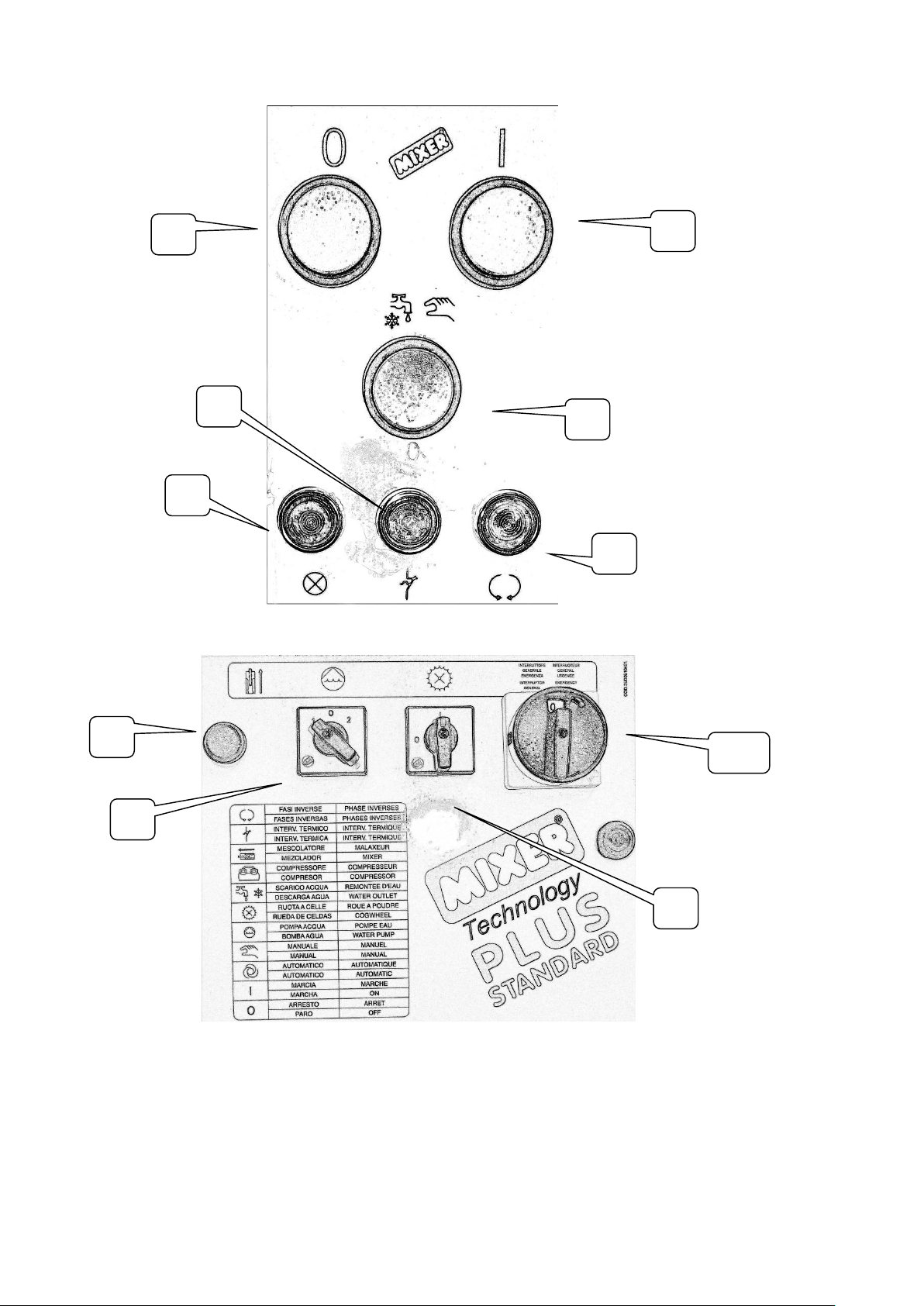
PLUS STANDARD CONTROL PANEL
1
2
4
6
7
10
3
5
9
8
Manual instruction Mixer Plus Mixer Technology srl pag.20
Page 21

RIF
COMMAND
FUNCTION
1
O
Stop machine
2
I
Run machine
3
Run
Winter drainage
4
Green Led
Voltage presence
5
Red Led
Tripping of the thermal protection gearmotor
6
Orange Led
Inverted phases
Off = correct phases;
On = incorrect phases, change the position of
the master switch
7
Reverse run
Reverses mixer direction motion
8
Water pump
1 = automatic
0 = stopped
2 = manual
9
Cell wheel
I = running
O = stopped
10
Main switch
1 = directed phases
0 = panel off
2 = inverted phases
Manual instruction Mixer Plus Mixer Technology srl pag.21
Page 22

CHECKS BEFORE SWITCHING ON
1) Make sure that there are not any non-authorized persons close to the
machine.
2) Make sure that the machine is braked and in horizontal plane.
3) Make sure that all components are properly installed.
4) Make sure that the main electric switch is in pos. “0” (off).
5) Make sure that the safety devices are integral, properly installed and
working.
6) Make sure that all shelves are correctly closed.
7) Make sure that the service taps and the system water drain are closed.
8) Make sure that the valve of the spraying nozzle is open.
9) Make sure that the plug of the power supply cable is connected to the plant
supplier and that the main electric switch is off.
10) Make sure that the air, water and material conveying tubes are well
stretched avoiding any constriction.
11) Make sure that the hopper drain door is closed.
12) Use the compulsory personal protective devices provided by own employer.
13) Verify the filter presence, if the water isn’t being drawn from water supply.
Manual instruction Mixer Plus Mixer Technology srl pag.22
Page 23

MACHINE PREPARATION
1) Supplies voltage to the electric panel.
2) Don’t let unattended on the machine.
3) Control of water flow rate in the mixing chamber:
a. Disconnect the water tube incoming in the trunket
1. If the pressure indicated from the gauge is lower than 4 bar,
position the water pump selector on “Manual”
2. If it is greater than 4 bar, position the water pump selector on
“Automatic”
b. Open the water solenoid valve enabling the selector marked by the
symbol “tap with drop” on the flow meter (fig. 1-26) check the water
flow rate
c. Set the water flow rate suggested: Cement type: 600 litres/min –
Gaseous type: 1000 litres/min
d. Connect the inlet water pipe of the mixing chamber inlet (To avoid
starting the machine in "idle" status, it is necessary to let a
minimum quantity of water (0.5 litres) enter the mixing chamber)
e. Open the water for at least 6 s.
4) Loading of the product:
a. Load the pre-mixed products on the hopper
b. Cutting them at the bottom with the cutting blade
c. Flow the product inside the hopper
5) Preparation of mixture:
a. Disconnect the material conveying tube from the machine material
output connection pulling the side levers (fig.1-28)
b. Position the water pump selector on “Automatic”;
c. Start the cell wheel;
d. Start the mixing;
e. Increase or decrease the water flow rate incoming in the trunket acting
on the related adjustment valve till obtaining the wished consistency;
f. Stop the machine;
g. Open the service tap (fig.1-18) to perform the internal wetting of the
material conveying tube; when the water comes out from the tube
close the tap and disconnect the tube;
h. Connect the material conveying tube to the machine material output
connection;
6) Plaster pressure regulation:
The pressure of the material at machine output determines the duration of the
stator (plenum chamber) and of the rotor (screw).
Manual instruction Mixer Plus Mixer Technology srl pag.23
Page 24

The recommend pressure depend from plaster types and from the second tube length
according to the following scheme:
o Cement type = 1 bar/metro
o Gaseous type = 0,8 bar/metro
Example: for processing gaseous type with the 15 meters tube the maximum
recommend pressure is 15 x 0,8 = 12 bar.
IT’S ABSOLUTELY FORBIDDEN TO USE THE MACHINE WITH MATERIAL
OUTPUT PRESSURE VALUES GREATER THAN 20 BAR
Manual instruction Mixer Plus Mixer Technology srl pag.24
Page 25

SPRAYING OF THE MATERIAL
1) Hold the spraying nozzle and direct it against the surface to be plastered;
2) Open (+) the valve on the spraying nozzle;
3) Adjust the spraying of the material moving forwards and/or backwards (+ or -),
the air tube acting on the screw and blocking it in the correct position;
4) To minimize the deterioration of stator/rotor group, avoid useless stops and
restarts of spray;
5) During work breaks less than 15 minutes, close the valve on the spraying
nozzle. For longer breaks must be execute the shutdown process;
6) In case of clogged of material conveying tube, enabling the mixer reverse run
selector for the time needed;
MACHINE SWITCHING OFF
1) Stop the cell wheel;
2) Continuing the spraying till from the spraying nozzle just water;
3) Closing the valve on the spraying nozzle;
4) Stop the mixing chamber;
5) After every shutdown, carry out the machine cleaning;
Manual instruction Mixer Plus Mixer Technology srl pag.25
Page 26
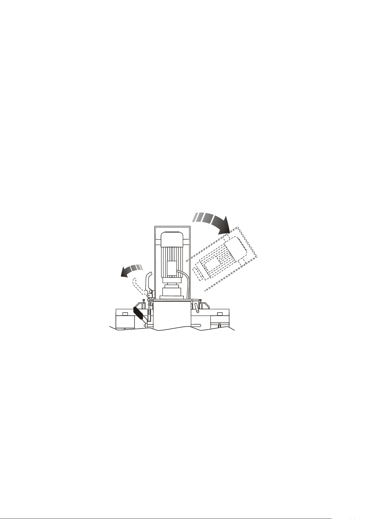
CLEANING OF CHAMBER MIXING
1) Only for mod. PLUS-MONO: Remove the gearmotor power supply outlet;
2) The machine can be externally cleaned with a sponge or damp cloth;
3) Open the gearmotor mixing assembly (see figure below);
4) Extract the mixer and clean it with the metallic brush (standard supplied);
5) Insert the rod in the cleaning device;
6) Manually insert the rod and cleaning device in the mixing chamber by
rotating manually the rod till it is connected into the radial cavity of the
rotor; N.B: Rotate the gearmotor joint coupling till the rod matches the
end;
7) Close the gearmotor assembly and hook it up;
8) Insert the power supply plug of the mixing gearmotor;
9) Start the mixer;
10) After 10 s (time cleaning necessary) stop the mixer;
11) Extract the cleaning device and the rod following the reverse procedure.
Manual instruction Mixer Plus Mixer Technology srl pag.26
Page 27
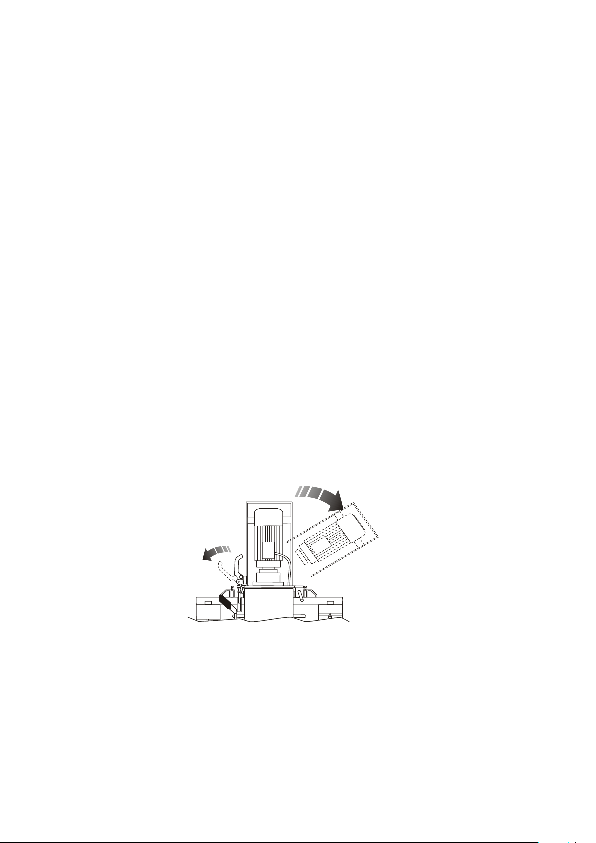
CLEANING OF THE HOPPER
At each change of the product used, it is suggested to perform the cleaning of the
hopper:
1) Place a suitable container under the hopper drain door and open this latter
(fig.1-14);
2) Remove the gearmotor power supply outlet (only mod. Plus Mono);
3) Disconnect the water tube from the trunket (fig. 1-11-12);
4) Open mixer assembly;
5) Rotate the gearmotor assembly flange clockwise;
6) Extract the mixer from the mixing chamber;
7) Stop and halt gearmotor assembly;
8) Open the mixing chamber locking lever(fig.1-3);
9) Remove the water tube to mixing chamber;
10) Rotate the mixing chamber, lifting it up from below;
11) Insert a sheet of paper or polypropylene between the hopper and the mixing
chamber;
12) Lower the mixing chamber and close the mixing chamber locking lever;
13) Reconnect the conveying water tube to mixing chamber;
14) Start the cell dosing wheel until the complete emptying of hopper;
15) Close the hopper drain door;
16) Open the mixing chamber and remove the sheet of paper or polypropylene;
17) Insert the mixer in the mixing chamber and connect it into the radial cavity of
the rotor;
18) Rotate the gearmotor assembly flange counter-clockwise, until correspond with
the mixer;
19) Close and stop the mixing gearmotor assembly;
20) Connect the water tube to mixing chamber.
Manual instruction Mixer Plus Mixer Technology srl pag.27
Page 28
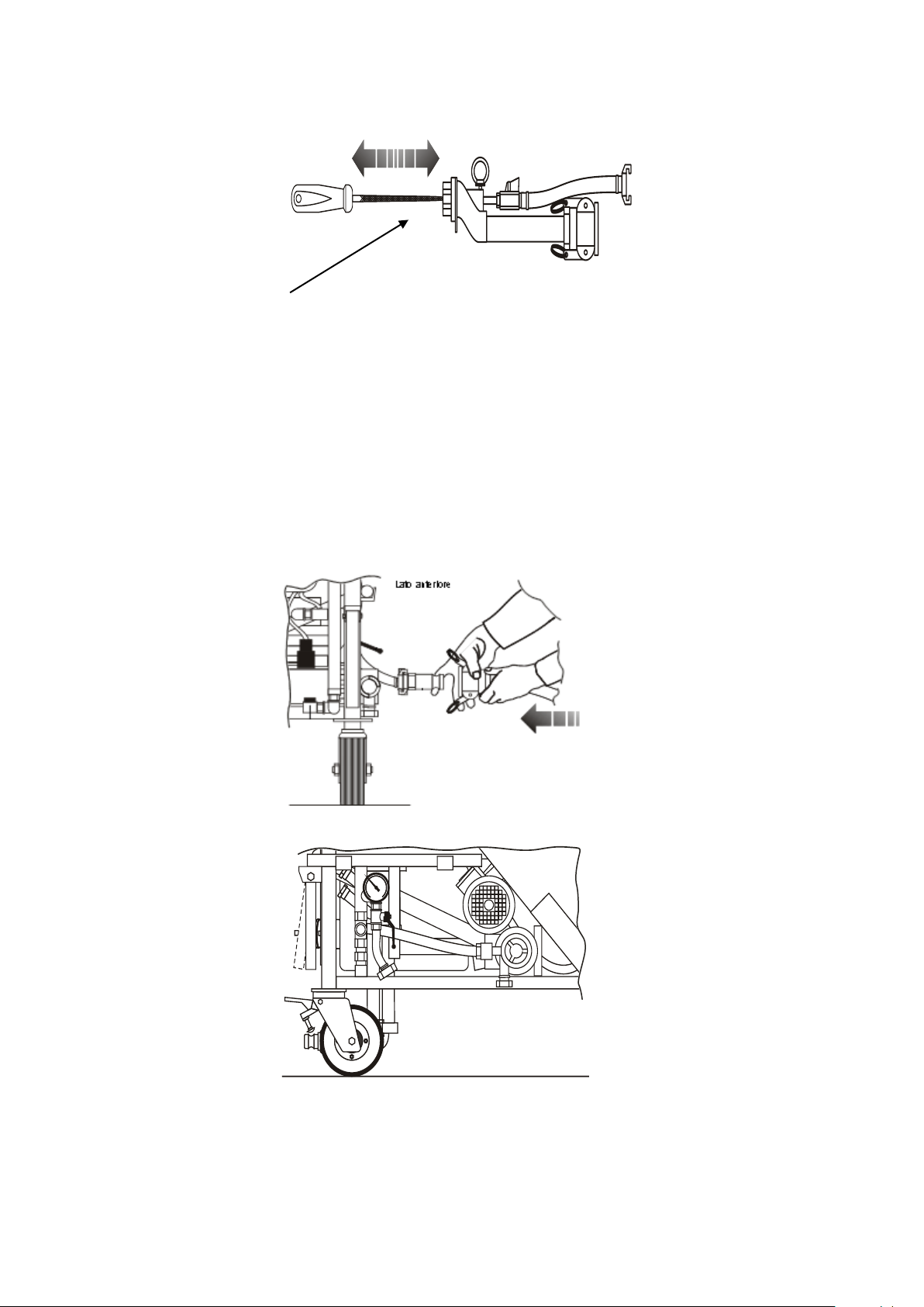
CLEANING OF THE SPRAYING NOZZLE AIR TUBE
1) Remove the diffuser and clean it with water;
2) Clean the air tube from any scaling using the specific brush supplied;
SWATER DRAINAGE DURING WINTER PERIOD
1) Disconnect the water inlet tubes of the machine and mixing chamber;
2) Open the tap of the system water drain;
3) Discharge the water opening the solenoid valve through the selector “Run -
Stop - Water drain during winter period” till no more water comes out.
Manual instruction Mixer Plus Mixer Technology srl pag.28
Page 29

RESEARCH OF MALFUNCTIONS
NR
ANOMALIES
CAUSES
SOLUTIONS
1
Flashing thermal
protections
warning led
Motors overload
Reset the circuit breaker. In case
of new intervention, remove the
cause.
2
Gear motor
protection
repeated
interventions
1 mixture too hard;
2) use of a too long
tube compared to the
material used;
3) use of not suitable
materials.
1) perform the reset of the
thermal switch tripping, (if
necessary, request the technical
service intervention) and re-start
the machine with more water;
2) reduce the length of the tube;
3) verify the product data
sheets.
3
The machine does
not start.
Power supply
Verify the connections of outlets
and plugs
4
Green
warning light
“lack of water”
blinks
Insufficient water
pressure;
Verify whether the water pump
had been enabled.
Verify the grip status of the
pump fittings.
Extract the water filter and clean
it, if necessary, replace it.
5
The gearmotor
does not start.
1) gearmotor under
stress;
2) tap of the
spraying nozzle
closed;
3) nozzle of the
spraying nozzle
clogged;
4) material scaling in
the mixing chamber
or ice;
1) Open the mixing chamber and
rotate the rotor to the right
using the proper "T" wrench.
In case of blocked rotor, replace
it;
2) open the tap of the spraying
nozzle;
3) carefully clean the nozzle of
the spraying nozzle;
4) disassemble the rotor / stator
assembly and carefully clean the
mixing chamber re-assemble the
rotor / stator assembly;
6
Water level in the
mixing chamber
is increasing.
1) mixer blocked;
2) mixer not
enabled;
3) excessive water
flow rate;
1a) verify that the mixer has
been started;
1b) verify the gearmotor power
supply cable;
The operations of research and remove of malfunctions must be done only by
competent and experienced staff.
All the intervention operations must be done in the absence of voltage.
Manual instruction Mixer Plus Mixer Technology srl pag.29
Page 30

NR
ANOMALIES
CAUSES
SOLUTIONS
4) stator/rotor
assembly tear.
1c) verify that the insertion of
the outlet in the electric plug of
the gearmotor;
1d) insert the power supply
plug;
2) insert the mixer;
3) reduce the water flow arte
indicated on the flow meter
acting on the adjustment valve;
4) replace the assembly stator
rotor.
7
The compressor
stops – thermal
protection
tripping
1) mechanical break
of the compressor
(with rod
malfunction);
2) clogged suction
filters;
3) cable or plug
damaged.
1) visible from outside (request
technical assistance);
2) replace the filters;
3) check cable and plug and
replace, if necessary.
8
The water pump
stops - thermal
protection
tripping
1) pump blocked;
2) cables and plug
damaged.
1) perform the reset of the
thermal protection tripping (if
necessary, request technical
assistance);
2) check the cable and the plug
and, if necessary, replace the
damaged parts.
9
The mixture
comes out from
the spraying
nozzle too liquid.
1) excessive water
flow rate;
2) mixture scaling on
the mixer;
3) obstruction of the
material output
connection.
1) reduce the water flow rate
acting slowly on the water
adjustment valve;
2) clean the mixer;
3) clean the material output
connection.
10
The mixture
comes out from
the spraying
nozzle too dense.
1) poor water
quantity;
2) mixer dirty;
3 mixing chamber
dirty.
1) increase the water flow rate
acting slowly on the water
adjustment valve;
2) clean the mixer;
3) clean the mixing chamber.
Manual instruction Mixer Plus Mixer Technology srl pag.30
Page 31

FREQUENCY
AREA
INTERVENTION
Every 10-15 hours
of work
Rotor (screw) stator
(plenum chamber) used
with cement products.
Replacement
Every 30-40 hours
of work
Rotor (screw) stator
(plenum chamber) used
with gaseous products.
Replacement
Every 100-150
hours of work
Mixer
Replacement
Daily
Safety devices
Functional verification
Material conveying tube,
air tube and power
supply cable.
Visual inspection of tear
status.
Weekly
Gearmotor.
Visual inspection and, if
necessary, topping up with
oil type BERGOIL
“BERGOFLUID 1000” or
equivalent.
Water filter.
Cleaning
Compressor filter.
Cleaning
Six-monthly
Compressor filters.
Replacement
Gaskets of chamber mixing
(Camix).
Replacement
Grease gun on flange
gearmotor cell wheels.
Replacement
Biennial
Material conveying tube
Replacement
ROUTINE MAINTENANCE
The operations of routine maintence must be done only by competent and
experienced staff.
The replacement of the machine components must be carried out only with original
spare parts.
Manual instruction Mixer Plus Mixer Technology srl pag.31
Page 32
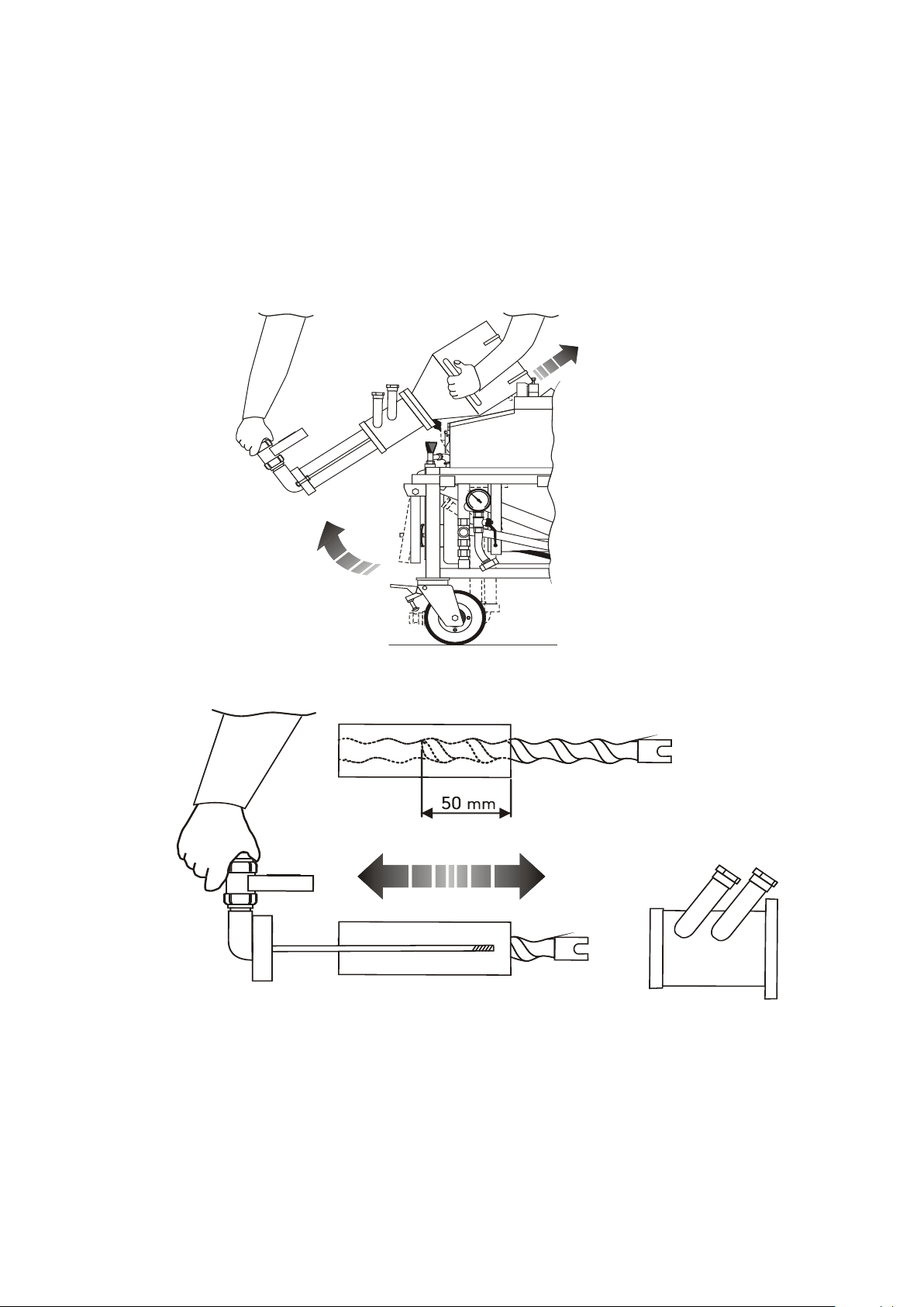
REPLACEMENT OF THE ROTOR STATOR
1. Remove the material output connection
2. Unhook and lift the chamber mixing
3. Block it in upper position
4. Unscrew the nuts of the tie rods and extract the rotor/stator assembly;
5. Spray the “Anti-grip” liquid (standard supplied bottle) on the new rotor;
6. Start the new rotor for at least 50 mm;
7. Mount the rotor/stator assembly, by screwing the nuts of the tie rods.
Manual instruction Mixer Plus Mixer Technology srl pag.32
Page 33

WARRANTY
1) Within the limits set forth by this warranty, the undersigned manufacturer
undertakes to repair all possible construction damages that may arise during the warranty
period of 12 (twelve) months for a daily use of 8 (eight) working hours. Such term shall
elapse as follows:
a) From the delivery date (Ref. transport document and sale invoice), if the
machine is sold directly to the Customer;
b) From the date given on the “Testing and Commissioning Certificate”, if the
Manufacturer or the Authorized Dealer performs the testing and commissioning of the
machine;
c) From the date of sale (Ref. transport document and sale invoice), if the machine is sold
directly by an Authorized Dealer on a "sale or return" basis; The obligations resulting from
the warranty decay in case of suspension or modification of the payment terms agreed
upon.
2) The warranty decays, if the purchaser does not duly observe the provisions
described in the “Instructions for Use and Maintenance” of the machine.
3) Remain excluded from the warranty: Failures and defects due to the normal tear of
those parts, which for their nature are subject to rapid and fast tear; electric
equipment; failures resulting from the use of tools and accessories not directly supplied
by the manufacturer.
4) In order to be able to exercise the warranty right, the purchaser has to inform the
manufacturer in case of defect detection immediately and, in any case, not later than 8
(eight) days from the detection date; moreover, it has to allow, if deemed necessary by
the same, the performance of the related inspections and repairing interventions.
5) The shipment of the faulty part, covered by the warranty, to the manufacturer for the
repairing or replacement of the same is at purchaser's charge. The warranty obligations,
as foreseen by this clause, are deemed fulfilled with the delivery to the purchaser of the
part duly repaired or replaced.
6) During the warranty period set forth by clause 1) labour costs, for the exclusive
duration of the intervention, are at manufacturer’s charge.
Should the repairing or replacement procedures be carried out where the machine is
installed, travel and lodging expenses of the personnel are at purchaser's charge.
7) Remain in any case excluded from the warranty, all faults caused by wrong
manoeuvre, negligence, fortuitous event or in any case all faults imputable to the user, in
person or through third parties, or when the purchaser has carried out modifications or
repairing interventions without the written consent of the manufacturer, independently
from the connection of such modifications or repairing interventions with the detected
faults.
8) It is explicitly agreed upon, that the manufacturer shall not be held responsible for any
liability following any possible damages that the purchasers may suffer resulting from loss
of or diminished production due to possible construction defects subject to this warranty.
Manual instruction Mixer Plus Mixer Technology srl pag.33
Page 34

Thank you for choosing our product
MIXER TECHNOLOGY srl
Via dei Carabinieri, 45, 36040
Torri di Quartesolo (VI) Italy
www.mixersrl.com
Manual instruction Mixer Plus Mixer Technology srl pag.34
 Loading...