

Mityvac MV7300 User Manual
MODEL/MODÈLE/MODELO MV7300
Recommended Inlet
Air Pressure: 80 - 120 psi
(5.5 - 7 bar)
Pression d’admission
d’air recommandée : 5,5 - 7 bars
(80 - 120 psi)
Presión de aire de entrada
recomendada:80 -120 lb/pulg²
(5.5 - 7 bares).
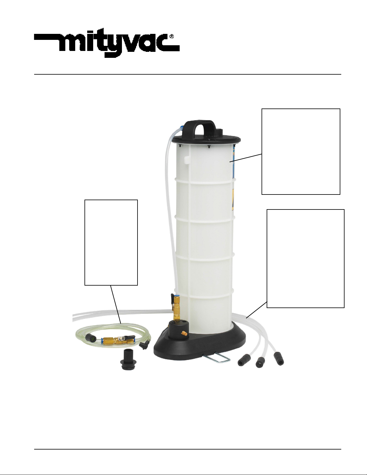
PNEUMATIVAC
8.8 Liter/9.3 Quarts Capacity
Capacité 8,8 Litres/9,3 Pintes
Capacidad de 8,8 litros/9,3 cuartos de galón
8.8 liter
Reservoir Tank
Réservoir de 8,8
litres
Depósito de 8,8
litros
Brake
Bleeder
Purgeur de
Frein
Purgador de
frenos
Dipstick
Tubes
Tubes de jauge
d’huile
Tubos de varilla
indicadora de
nivel
MAR - 2009
Form 824555
Section
- MV12
Page
- 1D

©Precautions:
This equipment is designed for servicing a variety of vehicles in a safe and convenient manner. However, differences
in engine blocks and dip stick congurations may make it impossible to use this equipment on every vehicle. The
procedures documented in this manual are to serve as guidelines for general use of this equipment. In addition to
these guidelines, always follow the manufacturer’s recommended procedures when attempting to use this equipment
on each unique vehicle. Do not attempt to force the tubes included with this equipment into a dip stick tube that will
not readily accept the smaller of the two tubes. The tubes would appear to be too large and not designed to be used
with the particular vehicle.
Draining oil with this evacuator unit through the dipstick tube is expected to be simple and straightforward. The instructions were written as a general guideline only.
NOTE: DO NOT FORCE THE TUBE INTO ANY CRANKCASE AND MAKE SURE THAT YOU STOP PUSHING
THE TUBE IN IF ANY FORCE IS RECOGNIZED. YOUR PARTICULAR DEALER SHOULD BE CONTACTED FOR
DETAIL ON USING THIS EQUIPMENT TO EVACUATE OIL FROM YOUR CAR IF ISSUES ARISE.
Always read carefully and understand instructions prior to using this equipment.
Tighten lid-to-reservoir screws befor rst use and periodically to ensure proper seal.
Recommended Fluids:
Engine Oil, Gear and Transmission Oils, Power Steering Fluid, Coolants, Brake Fluid and Other Fluids.
Do not use with gasoline.
Using the PneumatiVac away from a Compressed Air Source
The PneumatiVac is equipped with an air control valve on the Venturi at the base of the unit and an in-line uid shut
off valve on the hose assembly. This allows the unit to function away from the air source as follows:
• Once the compressed air source has been connected to the Venturi, open the air control valve and close the in-line
uid shut off valve.
• Maintain a vacuum in the reservoir and then close the air control valve.
• Disconnect the PneumatiVac from the compressed air source and transport it to your job site.
• Open the in-line uid shut off valve and the vacuum stored in the reservoir will automatically suction out the uid.
When used in conjunction with the Mityvac® Fluid Evacuator Brake Bleeding Accessory Kit, PIN 07205, this tool can
be used to vacuum bleed hydraulic brake systems.
The reservoir tank of the Pneumativac is equipped with an automatic shut-off valve to prevent over-lling of the reservoir tank. As the uid being evacuated ows into the reservoir tank it will raise the oat. When the oat reaches the
shut-off valve, the ow of uid being extracted will automatically stop.
Extracting and Dispensing Lubricants (General)
(Motor oil, Gear Oil, Transmission Fluid, etc.)
Extracting and Dispensing Motor Oil into a Crankcase
1. Park vehicle on level ground, ensure the transmission of the vehicle is in “neutral” or “park” position and apply
the parking brake.
2. Start the engine. Allow the engine to idle until it reaches normal operating temperature. Once this is accomplished, turn engine off.
3. Remove the engine oil dipstick.
4. Select and insert the smallest diameter dipstick tube into the dipstick hole until it reaches the bottom of the oil
pan. Connect the main suction tube to the dipstick tube.
5. Insert the opposite end of the main suction tube into the top of the reservoir tank.
6. Connect air hose to the venturi at the base of the PneumatiVac. This will require a male 1/4” NPT tting (not
included).
7. Open the air valve thereby creating a vacuum inside the reservoir tank that will be used to extract the uids.
© Indicates change
Page Number - 2
Form 824555
NOTE: Due to the varying uid capacities of engines, it may be necessary to empty the uid reservoir tank and
restart the process if the crankcase capacity exceeds 8 liters.
8. Once the oil has been extracted from the crankcase, remove the main suction tube from the reservoir tank; pour
the oil from the tank into a suitable container, and dispose of the oil in an appropriate manner. Rinse out the
reservoir tank with clean solvent or engine degreaser. Allow it to dry thoroughly.
9. Relled the crankcase to the desired level.
10. Run the engine momentarily to circulate the new oil and then recheck the level to ensure that it is at the “full”
mark.
Extracting and Dispensing Fluid into Transmission Cases and Differentials
1. Follow Steps 1 & 2. (See Extracting and Dispensing Motor Oil into a Crankcase)
2. Remove the transmission uid dipstick or ll plug.
In some applications this may require jacking or lifting the vehicle. Use appropriate safety stands to
avoid serious or fatal injury.
3. Select and insert the appropriate diameter dipstick tube into the dipstick ll hole until it reaches the bottom of the
transmission pan or gear case. Connect the main suction tube to the dipstick tube.
4. Insert the opposite end of the main suction tube into the top of the reservoir tank.
5. Connect air hose to the venturi at the base of the PneumatiVac. This will require a male 1/4” NPT tting (not
included).
6. Open the air valve thereby creating a vacuum inside the reservoir tank that will be used to extract the uids.
7. Once the desired amount of uid has been extracted, close the air control valve to stop the extraction process.
8. Remove the main suction tube from the reservoir tank; pour the transmission uid from the tank into a suitable
container, and dispose of the transmission uid in an appropriate manner. Rinse out the reservoir tank with clean
solvent or engine degreaser. Allow it to dry thoroughly.
9. Rell the transmission to the desired level.
10. Run the engine until it reaches operating temperature to circulate the new uid and then re-check the level to
ensure that it is full.
Extracting and Dispensing Coolant into a Cooling System
1. Allow the engine to cool.
2. Remove the radiator I expansion tank cap.
3. Select the largest diameter dipstick tube and insert the tube into the radiator neck or expansion tank.
4. Insert the opposite end of the main suction tube into the top of the reservoir tank.
5. Connect air hose to the venturi at the base of the PneumatiVac. This will require a male 1/4” NPT tting (not
included).
6. Open the air valve thereby creating a vacuum inside the reservoir tank that will be used to extract the uids.
7. Once the desired amount of uid has been extracted, close the air control valve to stop the extraction process.
8. Remove the main suction tube from the reservoir tank; pour the uid from the tank into a suitable
container, and dispose of the uid in an appropriate manner. Rinse out the reservoir tank with clean solvent or
engine degreaser. Allow it to dry thoroughly.
9. Rell the system to the desired level.
10. Run the engine until it reaches operating temperature to circulate the new uid and then re-check the level to
ensure that it is full.
Form 824555
Page Number - 3
Extracting Brake Fluid from the Master Cylinder
1. Clean the exterior of the master cylinder and master cylinder cap. (This will prevent dirt from entering the master
cylinder reservoir when the cap is removed.)
2. Remove the lid of the master cylinder reservoir.
Prior to inserting the extraction tube into the master cylinder reservoir, be sure that the extraction tube
is clean and free of any other types of uid. Failure to do so would result in contamination of the brake
uid in the hydraulic system and cause potential brake failure.
3. Select the appropriate “dipstick” tube and connect it to the main suction tube.
4. Insert the opposite end of the main suction tube into the top of the reservoir tank.
5. Insert the end of the extraction tube into the master cylinder reservoir.
6. Connect air hose to the venturi at the base of the PneumatiVac. This will require a male 1/4” NPT tting (not
included).
7. Open the air valve thereby creating a vacuum inside the reservoir tank that will be used to extract the uids.
6. Once the break uid has been extracted, remove the main suction tube from the reservoir tank; pour the break
uid from the tank into a suitable container, and dispose of it in an appropriate manner. Rinse out the reservoir
tank with clean solvent or engine degreaser. Allow it to dry thoroughly.
7. After all repairs are accomplished, rell the system with new, manufacturer approved brake uid from a sealed
container.
MAXIMUM TEMPERATURE OF FLUIDS: 176° Fahrenheit, 80° Celsius
Page Number - 4
Form 824555
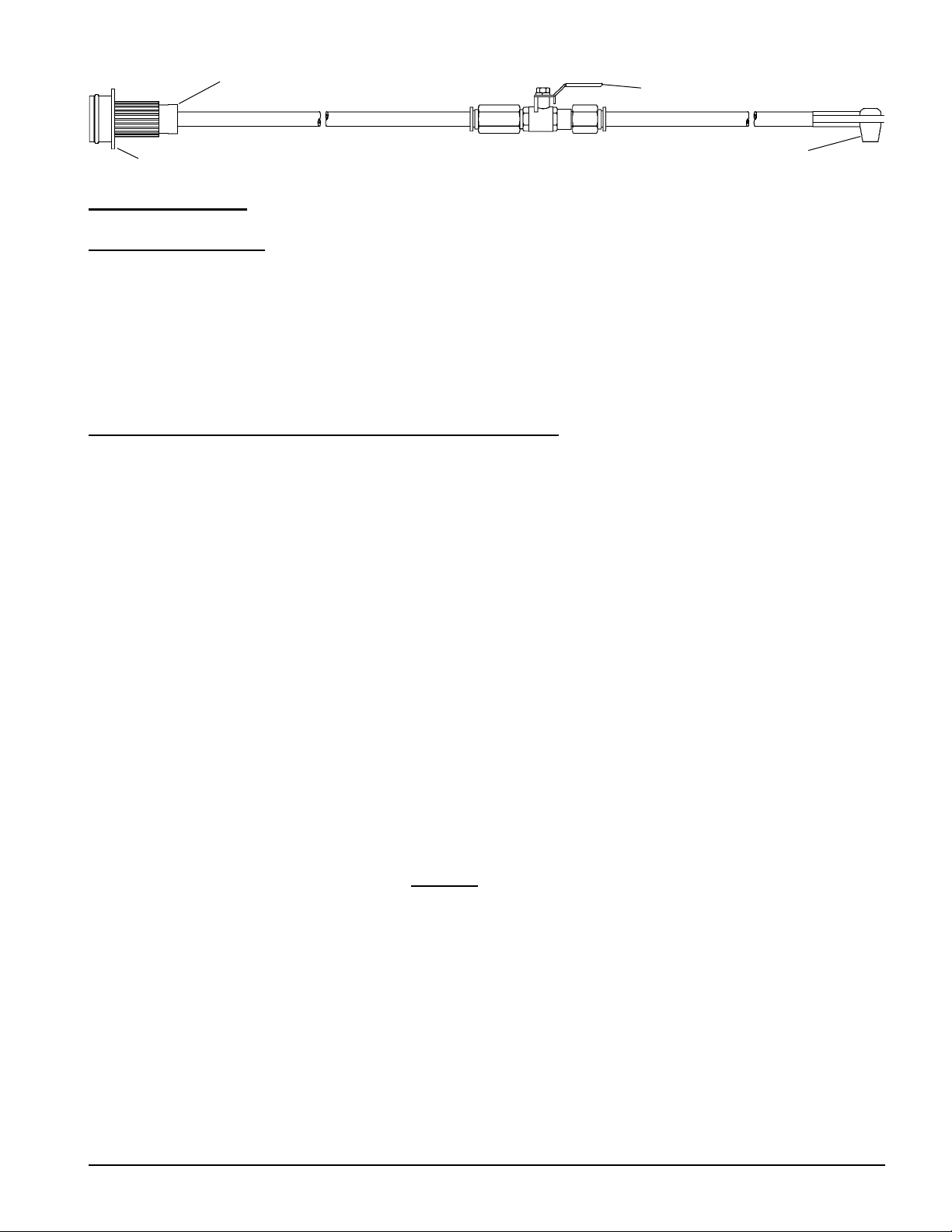
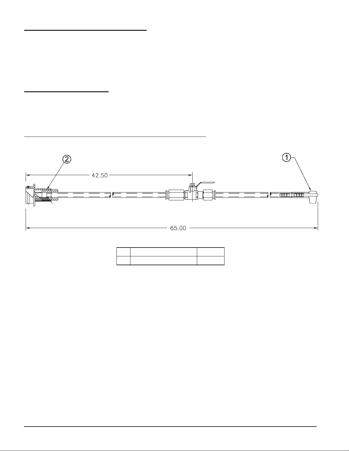
Rubber Connector
Control Valve
Tank Connector
Brake Bleeding Adapter
Bleeding Brakes
Instructions for Setup:
1. Select the brake bleeding hose and connect one end to the in-line uid shut off valve. Connect the
main connector to the reservoir tank and the universal bleeding elbow to the bleeder screw.
2. Close the in-line uid shut off valve (handle of valve will be turned 90 degrees from hose).
3. Connect air hose to the Venturi at the base of the PneumatiVac. This will require a male 3/4” NPT
tting that is used with your system (not included).
4. Open the air shut off valve thereby creating a vacuum inside the reservoir tank that will be used to
bleed the brakes.
The following brake bleeding procedure is recommended:
1. Ensure master cylinder reservoir is full of the specied uid and new dean uid is available to top
off reservoir during bleeding procedure. Ensure all bleeder ttings are clean at the start of bleeding
procedure.
2. Bleed system in the following order:
a. Master cylinder (if necessary). See the Bench Bleeding Procedure below if a new or rebuilt master
cylinder is being installed.
b. ABS controller (if necessary).
c. Wheel cylinders and calipers in succession beginning with the wheel closest to the master cylinder
and working to the farthest one.
3. Place wrench on the nut of the bleeder screw.
4. Connect brake bleeding adapter onto bleeder screw.
5. Open the air shut off valve by turning it to the “OPEN” position, thereby creating a vacuum required for
bleeding.
6. Open the bleeder screw slightly, only enough to cause uid to ow into the bleeder hose and continue
into the PneumatiVac™ (usually 1/4 to 1/2 turn).
7. After evacuating, approximately 1/4 of the master cylinder reservoir capacity, tighten the bleeder
screw. Add new brake uid to the master cylinder so it remains full then proceed to the next wheel.
NOTE: A tiny stream of bubbles may be noted in the bleeder hose after the bleeding procedure. This is
caused by air seeping around the threads of the loosened bleeder screw and is drawn through
the tting by the suction created by the Fluid Evacuator. Once the air has been removed from
the system, these tine air bubbles DO NOT jeopardize the bleeding operation since they are only
present at the external surface of the oeder tting and not in the system. If desired, bleeder
tting threads may be sealed with Teon® tape to help eliminate this condition.
NOTE: When nished using the PneumatiVac, contents should be emptied into an approved waste
container. Rinse reservoir with water, or solvent where applicable.
Form 824555
Page Number - 5
Bleeding Anti-Lock Brake Systems
Always refer to the vehicle’s owner manual or the appropriate service manual for manufacturer’s brake
bleeding procedure. The front brakes on most anti-lock brake systems may be bled in the conventional
manner. Most hydraulic pump/pressure accumulator units are tted with a bleeder valve, which must
be bled when the system has lost uid or is being replaced. Some vehicles require that the system
be pressurized when the rear brakes are bled. Acura, Ford and General Motors require a bleeding
procedure, which uses specialized equipment.
Bench Bleeding System
Whenever a master cylinder has been removed from a vehicle or a new one is being installed, the master
cylinder must be bench bled. Failure to bench bleed is the main reason for unsuccessful master cylinder
replacement. Bench bleeding greatly decreases the chance that any air will be caught in the cylinder
upon reinstallation. Most manufacturers include a bench bleeding kit with new or remanufactured master
cylinders. If this kit was not included with the replacement part to be installed, consult with your retailer
prior to installing the new or rebuilt master cylinder on the vehicle.
Item Description Part No.
1 Brake Bleeding Adapter * 822664
* Consists of three adapters
Page Number - 6
Form 824555
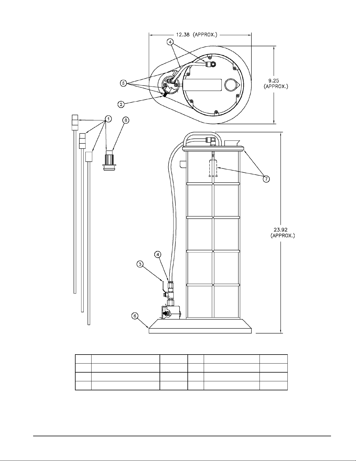
Model MV7300 Service Items
Item Description Part No. Item Description Part No.
1 Vaccum Tube Kit 822599 5 Kit Venturi** 822647
2 Kit, Exhaust Mufer* 822644 6 Base Kit*** 822574
3 Kit, Control Valve 822645 7 Kit, Lid and Float**** 822648
4 Kit, Tube and Connectors 822646 8 Plastic Adapter 822597
* Consists of three mufers
** Consists of venturi and connectors
*** Consists of base and foot bracket
**** Consists of top and overll oat
Form 824555
Page Number - 7
 Loading...