

Mityvac MV6412, MV6400, MV6410, MV6840, MV6842 User Manual

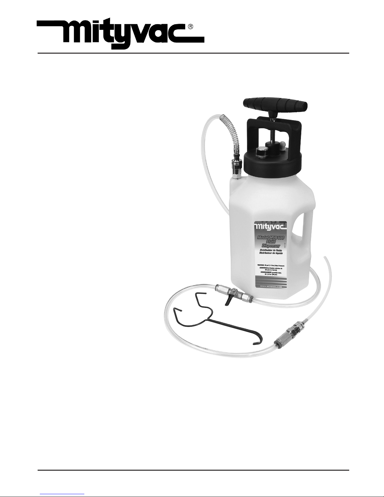
FLUID DISPENSING SYSTEM
MODELS MV6400,
MV6410, MV6412, MV6840, MV6842
USER’S MANUAL
Have a technical question?
Americas:
If you have questions, or require technical
service, please contact our trained service
technicians at:
1-314-679-4200 ext. 4782
Monday – Friday 7:30 am to 4:15 pm CST
Visit our website at www.mityvac.com for
new products, catalogs, and instructions
for product use.
Need service parts?
To order replacement or service parts, visit
us online at www.mityvacparts.com or call
toll free 1-800-992-9898.
MARCH 2015 Form 801193 Section - MV97-1E
It is the responsibility of the user of this equipment to read this user’s manual entirely,
and understand the safe and proper use and application of this equipment.
Specications:
Reservoir Capacity (w/ pump): 5 quarts/1.2 gallons/4.5 liters
Maximum Pressure: 25 psi/1.7 bar/170 kPa

Page Number - 2 Form 801193
TABLE OF CONTENTS
Service Parts & Accessories .........................................3
Principal of Operation ...............................................4
Applications ........................................................4
Precautions .........................................................4
Instructions for Use .................................................5
Fluid Dispensing ....................................................5
Pressure Brake Bleeding ............................................6
Refilling Sealed Automatic Transmissions ...........................7
Spanish .............................................................8
French .............................................................15
German ............................................................22
Warranty ...........................................................30
Form 801193 Page Number - 3
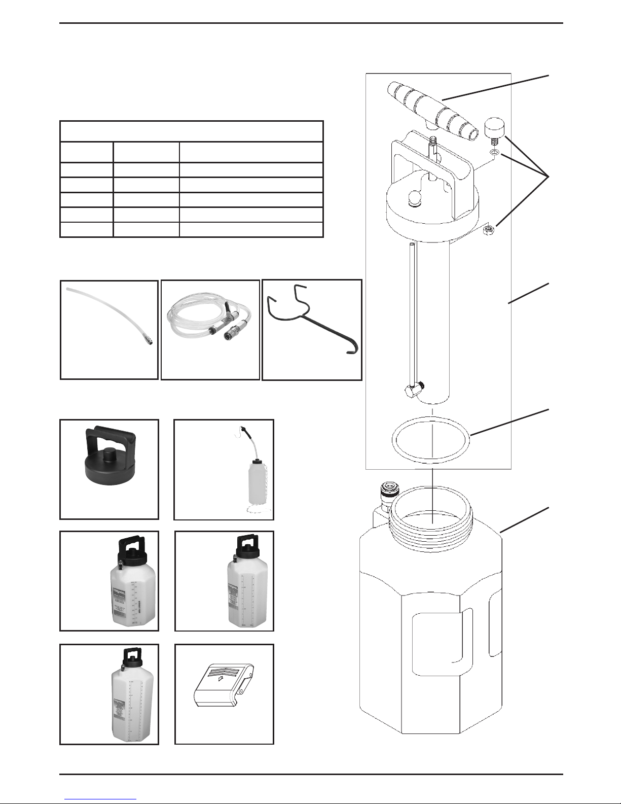
MVA575
Fluid Dispensing
Hose
MVA570 –
Fluid Dispensing
Wand
SERVICE KITS
Ref. No. Part No. Description
1 801230 Lid w/ Pump Assembly
2 801229 1-gallon Reservoir
3 801233 Lid Gasket
4 801234 Pressure Gauge
5 822561 Pump Handle
SERVICE PARTS & ACCESSORIES
3
1
2
5
4
STANDARD ACCESSORIES
OPTIONAL ACCESSORIES
MVA572 –
2.5 Gal. Reservoir
MVA6839 –
Pressure
Bleed Reservoir
MVA571 –
Fluid Storage Lid
MVA576 –
1.2 Gal. Reservoir
MVA573 –
5 Gal. Reservoir
822753 –
Hanging Hook
804789 – Latch

Page Number - 4 Form 801193
This equipment is designed and intended for use as a
means to dispense fluid. It utilizes a manual pressure
pump to build pressure in the reservoir. The pressure
forces fluid to dispense out of the reservoir through a
fluid pickup tube. The output of the fluid pickup tube
is connected to a quick-change coupler, to which a variety of accessories can be attached to control or direct
the flow of fluid according to the intended application.
The equipment should never be operated above a
safe level of pressure depending on the application. A
gauge is installed to indicate the pressure in the reservoir, and should be observed regularly to ensure the
pressure remains at or below what is recommended
for the application.
Applications
This equipment is intended for filling reservoirs with
fluids such as engine coolant, motor oil, or wiper,
automatic transmission, brake or power steering fluid.
However, with the proper accessories it can safely
be used to pressure bleed hydraulic brake or clutch
systems, or refill or top-off sealed automatic transmissions.
Precautions
This equipment is designed for servicing a variety
of vehicles in a safe, convenient manner. However,
differences in vehicle makes and models may make it
impossible to use this equipment as it is intended. Do
not attempt to force the use of this equipment on an
application for which it is not designed to perform.
The procedures documented in this manual are to
serve as guidelines for the use of this equipment. In
addition to these guidelines, always follow the manufacturer’s recommended procedures when servicing
each unique vehicle.
The use of this equipment is simple and straightforward if you follow the instructions. However, always
keep in mind that you are working with a system that
may be under pressure, with fluid that is just waiting
to be expelled. When operating this equipment,
use common sense, and always stop to think before
disconnecting a hose or other component.
• This equipment is intended only for professional use
by personnel trained in performing the service functions for which it is has been designed.
• Read carefully and understand all instructions prior
to using this equipment.
• Always wear eye protection and proper clothing
when operating this equipment
• Do not attempt to modify the pressure relief valve
to alter its performance. If pressure in the reservoir
ever exceeds 23 psi (1.6 bar), return it to an authorized service center for repair or replacement.
• Some fluids, including brake fluid, are corrosive,
and proper care should be taken to protect painted
surfaces and skin from exposure.
• Do not use this equipment with gasoline or other
flammable liquids, or with fluids at temperatures
above 175° Fahrenheit (80° Celsius).
• Consult and follow the vehicle manufacturer’s recommended procedure when using this equipment
to perform automotive service.
PRINCIPAL OF OPERATION

Form 801193 Page Number - 5
Fluid Dispensing
1. Unscrew the lid w/ pump from the reservoir, and
fill to desired level with clean fluid.
Note:There are two scales of volume on the res-
ervoir. One scale indicates the volume when the
lid w/ pump is removed and one when the lid w/
pump is installed. Be sure to note the appropriate
scale.
CAUTION: If fluid is added above the MAX FILL line,
the reservoir will overflow when the lid w/ pump is
installed.
2. Reinstall the lid w/ pump onto the reservoir.
3. Connect the fluid dispensing hose or other accessory to the quick-connect coupler extending from
the reservoir. Ensure the coupler sleeve snaps
forward to lock the
connection.
Note: Depending on the application, the shutoff
valve installed in the fluid dispensing hose may be
left open or closed. If left open, fluid will begin to
flow as soon as the pump is operated. If closed,
pressure will build in the reservoir as indicated on
the gauge.
4. While observing the pressure gauge, operate the
pump to build pressure in the reservoir to the
desired level, or until the desired amount of fluid
has been dispensed.
Note: A built-in pressure relief valve is designed to
open and maintain maximum pressure between
17 and 23 psi (1.2 and 1.6 bar).
Continual operation of the pump is not required
to maintain fluid flow. Fluid will continue to flow
as long as there is pressure in the reservoir and the
shutoff valve is open.
WARNING: Do not exceed 25 psi (1.7 bar) pressure
in the reservoir. The relief valve should prevent
this, but if it fails and the pressure exceeds 25 psi,
immediately discontinue use and send the unit to
an authorized service center for repair or replacement.
5. Once the proper amount of fluid has been dispensed, close the shutoff valve and bleed off the
pressure by tilting the pressure relief knob located
on the lid.
6. Depending on the type of fluid and future intended use, you may store the remaining fluid from the
reservoir. Otherwise empty the reservoir, clean it
with denatured alcohol or a common household
cleaner, and store it properly.
INSTRUCTIONS FOR USE

Page Number - 6 Form 801193
The Mityvac Fluid Dispensing System is appropriate
for use as a pressure bleeder for hydraulic brake and
clutch systems. Additional accessories and adapters
may be required and are available from Mityvac for
performing this function.
WARNING: Hydraulic/brake fluid is hazardous and corrosive. Take precautions to protect painted surfaces
and skin from exposure, and read and follow the fluid
manufacturer’s warnings and instructions.
1. Park the car, set the parking brake, and turn off the
engine.
2. Open and secure the hood.
3. Locate the brake or clutch master cylinder and
remove the cap.
4. Extract as much used hydraulic fluid from the
master cylinder reservoir as possible, and refill it
with new fluid.
5. Select the appropriate master cylinder pressure
bleed adapter and install it securely onto the
master cylinder reservoir.
6. Before adding fluid to the Dispenser, connect the
fluid dispensing hose to the female quick-connect
coupler extending from the reservoir. Ensure the
coupler sleeve snaps forward to lock the connection.
7. Connect the other end of the fluid dispensing hose
to the male quick-connect coupler on the master
cylinder pressure bleed adapter. Ensure the coupler sleeve snaps forward to lock the connection.
8. Ensure the shutoff valve is open, and operate the
manual pump to pressurize the system to 10 psi
(0.7 bar).
9. Watch the pressure gauge to ensure there are no
leaks. If the pressure drops, relieve the remaining
pressure in the system by tilting the pressure relief
knob located on the lid, remove and retighten the
lid from the dispensing reservoir and the adapter
on the master cylinder reservoir, and recheck the
system for leaks.
WARNING: Serious injury and/or equipment
damage can occur if the lid is removed from the
dispensing unit or the adapter from the master cylinder, without first relieving the system pressure.
10. Once you’ve proven all connections are secure
and the master cylinder adapter does not leak,
remove the lid w/ pump from the dispensing unit
and add up to 2 quarts (2 liters) of a manufacturer’s
recommended new hydraulic fluid from a sealed
container.
11. Reinstall the lid w/ pump and tighten it securely.
12. Consult a service manual to determine the recommended bleed pressure and the proper bleeding
sequence for the vehicle being serviced.
13. Observing the pressure gauge, operate the pressure pump to achieve the recommended pressure.
14. Connect the bleed reservoir to the bleed screw of
the first cylinder to be bled.
15. Open the bleed screw. Allow fluid to flow out until
only clear new fluid with no visible air bubbles is
streaming from the screw, and then re-tighten the
bleed screw to the manufacturer’s recommended
torque.
16. Perform the same procedure on all remaining
bleed screws. Operate the pressure pump as
required to maintain adequate pressure.
Note: Do not allow the dispensing unit and master
cylinder reservoir to run dry. Use the pressure
relief valve to relieve the pressure and add new
fluid if necessary.
17. Once bleeding is complete, relieve the pressure
in the reservoir and master cylinder by tilting
the pressure relief knob located on the lid of the
dispensing unit.
18. Close the fluid dispensing hose shutoff valve, and
carefully remove the adapter from the master
cylinder, being careful not spill any brake fluid.
19. Extract excess fluid or top-off the master cylinder
as required, and replace the cap.
20. Dispose of any hydraulic fluid remaining in the
Dispenser. Do not store hydraulic fluid in the reservoir. Clean the dispensing unit with denatured
alcohol and store it properly.
21. Test the brake or clutch system for leaks before
driving the car.
The Mityvac Fluid Dispensing System is appropriate for
use to refill or top-off sealed automatic transmissions.
Additional accessories and adapters may be required
and are available from Mityvac for performing this
function.
PRESSURE BRAKE BLEEDING

Form 801193 Page Number - 7
1. Unscrew the lid w/ pump from the reservoir, and
fill to desired level with new vehicle manufacturer’s recommended transmission fluid.
CAUTION: Lifetime “sealed” transmissions require
the use of special manufacturer recommended
fluids. Use of any other fluids may cause severe
damage to the transmission and void the manufacturer’s warranty.
Note: There are two scales of volume on the res-
ervoir. One scale indicates the volume when the
lid w/ pump is removed and one when the lid w/
pump is installed. Be sure to note the appropriate
scale.
CAUTION: If fluid is added above the MAX FILL line,
the reservoir will overflow when the lid w/ pump is
installed.
2. Reinstall the lid w/ pump onto the reservoir.
3. Connect the fluid dispensing hose to the reservoir
using the quick-connect coupler. Ensure the coupler sleeve snaps forward to lock the connection.
Note: The shutoff valve installed in the fluid
dispensing hose may be left open or closed. If left
open, fluid will begin to flow as soon as the pump
is operated. If closed, pressure will build in the
reservoir as indicated on the gauge.
4. Select the appropriate ATF refill adapter for the application and connect it to the output of the fluid
dispensing hose.
5. Insert or connect the ATF refill adapter to the
transmission.
6. While observing the pressure gauge, operate the
pump to build pressure in the reservoir to the
desired level, or until the proper amount of fluid
has been dispensed.
Note: Check the vehicle’s service manual to deter-
mine the proper method to check the transmission
fluid level. Failure to follow the manufacturer’s
recommended procedure could result in underor over-filling the transmission, causing severe
transmission damage.
The pressure relief valve is designed to open and
maintain maximum pressure between 17 and 23
psi (1.2 and 1.6 bar).
Continual operation of the pump is not required
to maintain fluid flow. Fluid will continue to flow
as long as there is pressure in the reservoir and the
shutoff valve is open.
WARNING: Do not exceed 25 psi (1.7 bar) pressure
in the reservoir. The relief valve should prevent
this, but if it fails and the pressure exceeds 25 psi,
immediately discontinue use and send the unit to
an authorized service center for repair or replacement.
7. Once the proper amount of fluid has been
dispensed, close the shutoff valve on the fluid dispensing hose and bleed off the pressure by tilting
the pressure relief knob located on the lid.
8. Depending on the type of fluid and future
intended use, store or empty the remaining fluid
from the reservoir.
9. Clean the unit with denatured alcohol or common
household cleaners, and store it properly.
REFILLING SEALED AUTOMATIC TRANSMISSIONS
SISTEMA DE DISTRIBUCIÓN DE FLUIDO
MODELOS MV6400,
MV6410, MV6412, MV6840, MV6842
MANUAL DEL USUARIO
¿Tiene dudas técnicas?
América:
Si tiene dudas, o necesita servicio técnico, póngase en
contacto con nuestros técnicos de servicio capacitados
llamando al:
1-314-679-4200 ext. 4782
De lunes a viernes de 7:30 de la mañana a las 4:15 de la
tarde, hora del Centro. Visite nuestro sitio web en www.
mityvac.com para ver nuevos productos, catálogos e
instrucciones de uso del producto.
¿Necesita piezas de servicio?
Para pedir piezas de repuesto o servicio, visítenos en
línea en www.mityvacparts.com
o llame al teléfono gratuito 1-800-992-9898.
MARZO 2015 FORMULARIO 801193 Sección - MV97-1E
El usuario de este equipo tiene la responsabilidad de leer este manual del usuario en su
totalidad, y entender el uso seguro y apropiado y la aplicación de este equipo.
Especicaciones:
Capacidad del depósito (con bomba): 5 cuartos de gal/1,2 galones/4,5 litros
Presión máxima: 25 lb/pulg2/1,7 bares/170 kPa

Formulario 801193 Número de página - 9
TABLE OF CONTENTS
Piezas de Repuesto y Accesorios ..................................10
Principio de Operación ............................................11
Aplicaciones .......................................................11
Precauciones .......................................................11
Instrucciones de Uso ...............................................12
Distribución de Fluido .............................................12
Purga de Frenos de Presión ........................................13
Relleno de Transmisiones Automáticas Selladas ...................14
Garantía ............................................................30
Número de página - 10 Formulario 801193
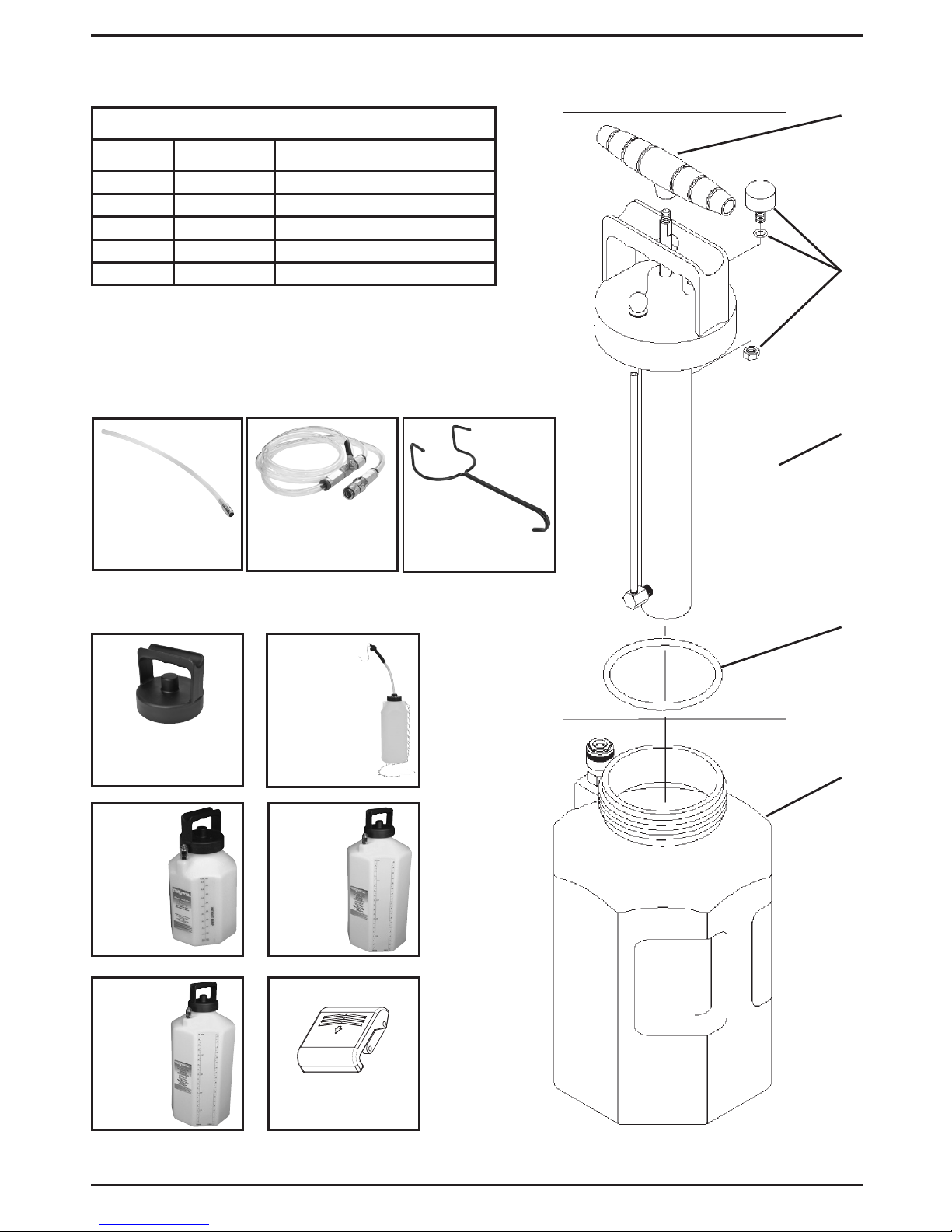
MVA575 –
Manguera de distri-
bución de uidos
MVA570 –
Varilla de distribución
de uido
JUEGOS DE SERVICIO
N° de ref. N° de pieza Descripción
1 801230 Tapa con conjunto de bomba
2 801229 Depósito de 1 galón
3 801233 Empaquetadura de la tapa
4 801234 Manómetro
5 822561 Palanca de la bomba
PIEZAS DE REPUESTO Y ACCESORIOS
3
1
2
5
4
ACCESORIOS ESTÁNDAR
ACCESORIOS OPCIONALES
MVA6839 –
Depósito de
purga de presión
MVA571 –
Tapa de almace-
namiento de uido
MVA576 –
Depósito de
1.2 galones
MVA572 –
Depósito
de 2.5 galones
MVA573 –
Depósito de 5
galones
822753 –
Gancho colgante
804789 – Pestillo
 Loading...