

Page 1

USER’S MANUAL
Have a technical question?
Americas:
If you have questions, or require technical
service, please contact our trained service
technicians at:
1-314-679-4200 ext. 4782
Monday – Friday 7:30 am to 4:15 pm CST
Visit our website at www.mityvac.com for
new products, catalogs, and instructions
for product use.
Need service parts?
To order replacement or service parts, visit
us online at www.mityvacparts.com or call
toll free 1-800-992-9898.
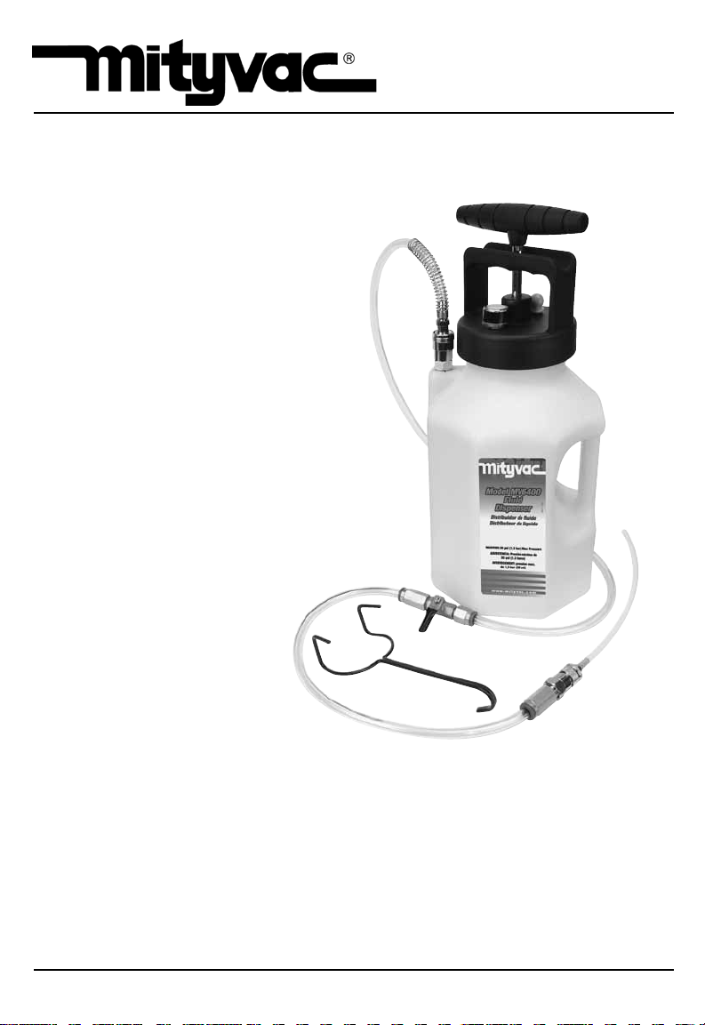
FLUID DISPENSING SYSTEM
MODELS MV6400,
MV6410, MV6840
Specifications:
Reservoir Capacity (w/ pump): 5 quarts/1.2 gallons/4.5 liters
Maximum Pressure: 25 psi/1.7 bar/170 kPa
It is the responsibility of the user of this equipment to read this user’s manual entirely,
and understand the safe and proper use and application of this equipment.
OCTOBER - 2010 Form 801193 Section - 97-1
Page 2

TABLE OF CONTENTS
Service Parts & Accessories . . . . . . . . . . . . . . . . . . . . . . . . . . . 3
Principal of Operation . . . . . . . . . . . . . . . . . . . . . . . . . . . . . . . . 4
Applications . . . . . . . . . . . . . . . . . . . . . . . . . . . . . . . . . . . . . . . . 4
Precautions . . . . . . . . . . . . . . . . . . . . . . . . . . . . . . . . . . . . . . . . . 4
Instructions for Use . . . . . . . . . . . . . . . . . . . . . . . . . . . . . . . . . . 5
Fluid Dispensing . . . . . . . . . . . . . . . . . . . . . . . . . . . . . . . . . . . . . 5
Pressure Brake Bleeding . . . . . . . . . . . . . . . . . . . . . . . . . . . . . . 6
Refilling Sealed Automatic Transmissions . . . . . . . . . . . . . . . . 7
Spanish . . . . . . . . . . . . . . . . . . . . . . . . . . . . . . . . . . . . . . . . . . . . 8
French . . . . . . . . . . . . . . . . . . . . . . . . . . . . . . . . . . . . . . . . . . . . 15
German . . . . . . . . . . . . . . . . . . . . . . . . . . . . . . . . . . . . . . . . . . . 22
Warranty . . . . . . . . . . . . . . . . . . . . . . . . . . . . . . . . . . . . . . . . . . 30
Page Number - 2 Form 801193
Page 3
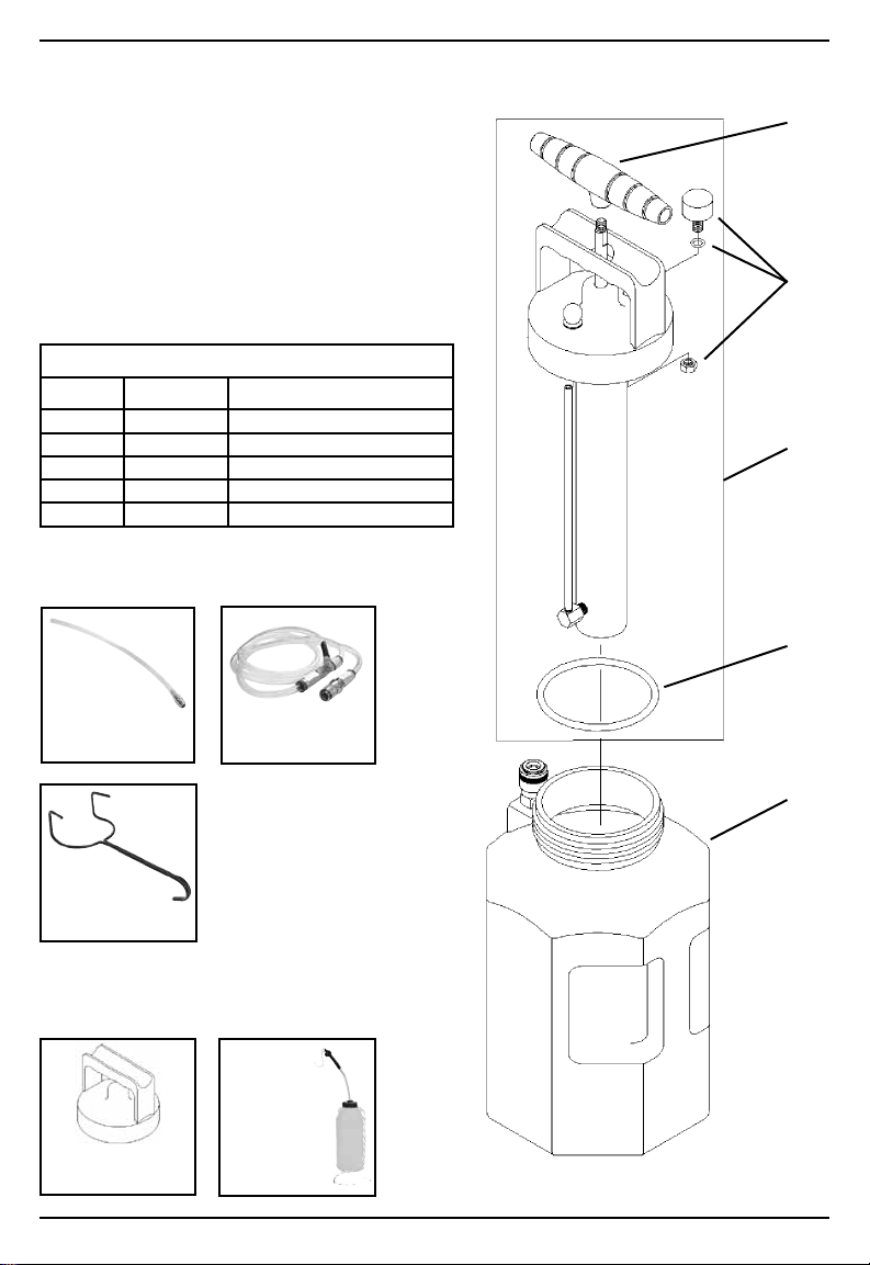
SERVICE PARTS & ACCESSORIES
SERVICE KITS
Ref. No. Part No. Description
1 801230 Lid w/ Pump Assembly
2 801229 1-gallon Reservoir
3 801233 Lid Gasket
4 801234 Pressure Gauge
5 822561 Pump Handle
STANDARD ACCESSORIES
5
4
1
3
MVA570 –
Fluid Dispensing Wand
MVA575 –
Fluid Dispensing Hose
2
822753 –
Hanging Hook
OPTIONAL ACCESSORIES
MVA6839 –
MVA571 –
Fluid Storage Lid
Form 801193 Page Number - 3
Pressure Bleed
Reservoir
Page 4

PRINCIPAL OF OPERATION
This equipment is designed and intended for use
as a means to dispense fluid. It utilizes a manual
pressure pump to build pressure in the reservoir.
The pressure forces fluid to dispense out of the
reservoir through a fluid pickup tube. The output
of the fluid pickup tube is connected to a quickchange coupler, to which a variety of accessories
can be attached to control or direct the flow of
fluid according to the intended application.
The equipment should never be operated above a
safe level of pressure depending on the application. A gauge is installed to indicate the pressure
in the reservoir, and should be observed regularly
to ensure the pressure remains at or below what is
recommended for the application.
Applications
This equipment is intended for filling reservoirs
with fluids such as engine coolant, motor oil, or
wiper, automatic transmission, brake or power
steering fluid. However, with the proper accessories it can safely be used to pressure bleed hydraulic brake or clutch systems, or refill or top-off
sealed automatic transmissions.
Precautions
This equipment is designed for servicing a variety
of vehicles in a safe, convenient manner. However, differences in vehicle makes and models
may make it impossible to use this equipment as
it is intended. Do not attempt to force the use of
this equipment on an application for which it is not
designed to perform.
The procedures documented in this manual are to
serve as guidelines for the use of this equipment.
In addition to these guidelines, always follow the
manufacturer’s recommended procedures when
servicing each unique vehicle.
The use of this equipment is simple and straightforward if you follow the instructions. However,
always keep in mind that you are working with a
system that may be under pressure, with fluid that
is just waiting to be expelled. When operating
this equipment, use common sense, and always
stop to think before disconnecting a hose or other
component.
• This equipment is intended only for professional
use by personnel trained in performing the service functions for which it is has been designed.
• Read carefully and understand all instructions
prior to using this equipment.
• Always wear eye protection and proper clothing
when operating this equipment
• Do not attempt to modify the pressure relief
valve to alter its performance. If pressure in the
reservoir ever exceeds 23 psi (1.6 bar), return
it to an authorized service center for repair or
replacement.
• Some fluids, including brake fluid, are corrosive,
and proper care should be taken to protect
painted surfaces and skin from exposure.
• Do not use this equipment with gasoline or other
flammable liquids, or with fluids at temperatures
above 175° Fahrenheit (80° Celsius).
• Consult and follow the vehicle manufacturer’s
recommended procedure when using this
equipment to perform automotive service.
Page Number - 4 Form 801193
Page 5

INSTRUCTIONS FOR USE
Fluid Dispensing
1. Unscrew the lid w/ pump from the reservoir,
and fill to desired level with clean fluid.
Note:There are two scales of volume on the
reservoir. One scale indicates the volume
when the lid w/ pump is removed and one
when the lid w/ pump is installed. Be sure to
note the appropriate scale.
CAUTION: If fluid is added above the MAX
FILL line, the reservoir will overflow when the
lid w/ pump is installed.
2. Reinstall the lid w/ pump onto the reservoir.
3. Connect the fluid dispensing hose or other
accessory to the quick-connect coupler extending from the reservoir. Ensure the coupler
sleeve snaps forward to lock the
connection.
Note: Depending on the application, the
shutoff valve installed in the fluid dispensing
hose may be left open or closed. If left open,
fluid will begin to flow as soon as the pump is
operated. If closed, pressure will build in the
reservoir as indicated on the gauge.
4. While observing the pressure gauge, operate
the pump to build pressure in the reservoir to
the desired level, or until the desired amount of
fluid has been dispensed.
Note: A built-in pressure relief valve is de-
signed to open and maintain maximum pressure between 17 and 23 psi (1.2 and 1.6 bar).
Continual operation of the pump is not re-
quired to maintain fluid flow. Fluid will continue
to flow as long as there is pressure in the
reservoir and the shutoff valve is open.
WARNING: Do not exceed 25 psi (1.7 bar)
pressure in the reservoir. The relief valve
should prevent this, but if it fails and the pressure exceeds 25 psi, immediately discontinue
use and send the unit to an authorized service
center for repair or replacement.
5. Once the proper amount of fluid has been dispensed, close the shutoff valve and bleed off
the pressure by tilting the pressure relief knob
located on the lid.
6. Depending on the type of fluid and future
intended use, you may store the remaining
fluid from the reservoir. Otherwise empty the
reservoir, clean it with denatured alcohol or
a common household cleaner, and store it
properly.
Form 801193 Page Number - 5
Page 6

PRESSURE BRAKE BLEEDING
The Mityvac Fluid Dispensing System is appropriate for use as a pressure bleeder for hydraulic
brake and clutch systems. Additional accessories
and adapters may be required and are available
from Mityvac for performing this function.
WARNING: Hydraulic/brake fluid is hazardous and
corrosive. Take precautions to protect painted
surfaces and skin from exposure, and read and
follow the fluid manufacturer’s warnings and
instructions.
1. Park the car, set the parking brake, and turn off
the engine.
2. Open and secure the hood.
3. Locate the brake or clutch master cylinder and
remove the cap.
4. Extract as much used hydraulic fluid from the
master cylinder reservoir as possible, and refill
it with new fluid.
5. Select the appropriate master cylinder pressure bleed adapter and install it securely onto
the master cylinder reservoir.
6. Before adding fluid to the Dispenser, connect
the fluid dispensing hose to the female quickconnect coupler extending from the reservoir.
Ensure the coupler sleeve snaps forward to
lock the connection.
7. Connect the other end of the fluid dispensing
hose to the male quick-connect coupler on
the master cylinder pressure bleed adapter.
Ensure the coupler sleeve snaps forward to
lock the connection.
8. Ensure the shutoff valve is open, and operate
the manual pump to pressurize the system to
10 psi (0.7 bar).
9. Watch the pressure gauge to ensure there are
no leaks. If the pressure drops, relieve the
remaining pressure in the system by tilting the
pressure relief knob located on the lid, remove
and retighten the lid from the dispensing reservoir and the adapter on the master cylinder
reservoir, and recheck the system for leaks.
WARNING: Serious injury and/or equipment
damage can occur if the lid is removed from
the dispensing unit or the adapter from the
master cylinder, without first relieving the
system pressure.
10. Once you’ve proven all connections are secure
and the master cylinder adapter does not leak,
remove the lid w/ pump from the dispensing unit and add up to 2 quarts (2 liters) of a
manufacturer’s recommended new hydraulic
fluid from a sealed container.
11. Reinstall the lid w/ pump and tighten it securely.
12. Consult a service manual to determine the
recommended bleed pressure and the proper
bleeding sequence for the vehicle being serviced.
13. Observing the pressure gauge, operate the
pressure pump to achieve the recommended
pressure.
14. Connect the bleed reservoir to the bleed screw
of the first cylinder to be bled.
15. Open the bleed screw. Allow fluid to flow out
until only clear new fluid with no visible air
bubbles is streaming from the screw, and then
re-tighten the bleed screw to the manufacturer’s recommended torque.
16. Perform the same procedure on all remaining
bleed screws. Operate the pressure pump as
required to maintain adequate pressure.
Note: Do not allow the dispensing unit and
master cylinder reservoir to run dry. Use the
pressure relief valve to relieve the pressure and
add new fluid if necessary.
17. Once bleeding is complete, relieve the pressure in the reservoir and master cylinder by
tilting the pressure relief knob located on the
lid of the dispensing unit.
18. Close the fluid dispensing hose shutoff valve,
and carefully remove the adapter from the
master cylinder, being careful not spill any
brake fluid.
19. Extract excess fluid or top-off the master cylinder as required, and replace the cap.
20. Dispose of any hydraulic fluid remaining in
the Dispenser. Do not store hydraulic fluid in
the reservoir. Clean the dispensing unit with
denatured alcohol and store it properly.
21. Test the brake or clutch system for leaks
before driving the car.
Page Number - 6 Form 801193
Page 7

REFILLING SEALED AUTOMATIC TRANSMISSIONS
The Mityvac Fluid Dispensing System is appropriate for use to refill or top-off sealed automatic transmissions. Additional accessories and
adapters may be required and are available from
Mityvac for performing this function.
1. Unscrew the lid w/ pump from the reservoir,
and fill to desired level with new vehicle manufacturer’s recommended transmission fluid.
CAUTION: Lifetime “sealed” transmissions
require the use of special manufacturer recommended fluids. Use of any other fluids may
cause severe damage to the transmission and
void the manufacturer’s warranty.
Note: There are two scales of volume on the
reservoir. One scale indicates the volume
when the lid w/ pump is removed and one
when the lid w/ pump is installed. Be sure to
note the appropriate scale.
CAUTION: If fluid is added above the MAX
FILL line, the reservoir will overflow when the
lid w/ pump is installed.
2. Reinstall the lid w/ pump onto the reservoir.
3. Connect the fluid dispensing hose to the reservoir using the quick-connect coupler. Ensure
the coupler sleeve snaps forward to lock the
connection.
Note: The shutoff valve installed in the fluid
dispensing hose may be left open or closed. If
left open, fluid will begin to flow as soon as the
pump is operated. If closed, pressure will build
in the reservoir as indicated on the gauge.
4. Select the appropriate ATF refill adapter for the
application and connect it to the output of the
fluid dispensing hose.
5. Insert or connect the ATF refill adapter to the
transmission.
6. While observing the pressure gauge, operate
the pump to build pressure in the reservoir to
the desired level, or until the proper amount of
fluid has been dispensed.
Note: Check the vehicle’s service manual to
determine the proper method to check the
transmission fluid level. Failure to follow the
manufacturer’s recommended procedure
could result in under- or over-filling the transmission, causing severe transmission damage.
The pressure relief valve is designed to open
and maintain maximum pressure between 17
and 23 psi (1.2 and 1.6 bar).
Continual operation of the pump is not re-
quired to maintain fluid flow. Fluid will continue
to flow as long as there is pressure in the
reservoir and the shutoff valve is open.
WARNING: Do not exceed 25 psi (1.7 bar)
pressure in the reservoir. The relief valve
should prevent this, but if it fails and the pressure exceeds 25 psi, immediately discontinue
use and send the unit to an authorized service
center for repair or replacement.
7. Once the proper amount of fluid has been
dispensed, close the shutoff valve on the fluid
dispensing hose and bleed off the pressure by
tilting the pressure relief knob located on the
lid.
8. Depending on the type of fluid and future intended use, store or empty the remaining fluid
from the reservoir.
9. Clean the unit with denatured alcohol or common household cleaners, and store it properly.
Form 801193 Page Number - 7
Page 8
MANUAL DEL USUARIO
¿Tiene dudas técnicas?
América:
Si tiene dudas, o necesita servicio técnico, póngase
en contacto con nuestros técnicos de servicio
capacitados llamando al:
1-314-679-4200 ext. 4782
De lunes a viernes de 7:30 de la mañana a las 4:15
de la tarde, hora del Centro. Visite nuestro sitio web
en www.mityvac.com para ver nuevos productos,
catálogos e instrucciones de uso del producto.
¿Necesita piezas de servicio?
Para pedir piezas de repuesto o servicio, visítenos
en línea en www.mityvacparts.com
o llame al teléfono gratuito 1-800-992-9898.
SISTEMA DE DISTRIBUCIÓN DE
FLUIDO MODELOS MV6400,
MV6410, MV6840
Especificaciones:
Capacidad del depósito (con bomba): 5 cuartos de gal/1,2 galones/4,5 litros
Presión máxima: 25 lb/pulg2/1,7 bares/170 kPa
El usuario de este equipo tiene la responsabilidad de leer este manual del usuario en su
totalidad, y entender el uso seguro y apropiado y la aplicación de este equipo.
OCTUBRE - 2010 FORMULARIO 801193 Sección - 97-1
Page 9

TABLE OF CONTENTS
Piezas de Repuesto y Accesorios . . . . . . . . . . . . . . . . . . . . . 10
Principio de Operación . . . . . . . . . . . . . . . . . . . . . . . . . . . . . . 11
Aplicaciones . . . . . . . . . . . . . . . . . . . . . . . . . . . . . . . . . . . . . . . 11
Precauciones . . . . . . . . . . . . . . . . . . . . . . . . . . . . . . . . . . . . . . 11
Instrucciones de Uso . . . . . . . . . . . . . . . . . . . . . . . . . . . . . . . . 12
Distribución de Fluido . . . . . . . . . . . . . . . . . . . . . . . . . . . . . . . 12
Purga de Frenos de Presión . . . . . . . . . . . . . . . . . . . . . . . . . . 13
Relleno de Transmisiones Automáticas Selladas . . . . . . . . . . 14
Garantía . . . . . . . . . . . . . . . . . . . . . . . . . . . . . . . . . . . . . . . . . . 30
Formulario 801193 Número de página - 9
Page 10

PIEZAS DE REPUESTO Y ACCESORIOS
JUEGOS DE SERVICIO
N° de ref. N° de pieza Descripción
1 801230 Tapa con conjunto de bomba
2 801229 Depósito de 1 galón
3 801233 Empaquetadura de la tapa
4 801234 Manómetro
5 822561 Palanca de la bomba
ACCESORIOS ESTÁNDAR
5
4
1
3
MVA570 –
Varilla de distribución
de fluido
MVA575 –
Manguera de distribución
de fluidos
2
822753 –
Gancho colgante
ACCESORIOS OPCIONALES
MVA571 –
Tapa de almacenamiento
de fluido
Número de página - 10 Formulario 801193
MVA6839 –
Depósito de purga
de presión
Page 11

PRINCIPIO DE OPERACIÓN
Este equipo está diseñado y tiene como finalidad
ser utilizado como medio de distribuir fluido. Utiliza una bomba de presión manual para aumentar
la presión en el depósito. La presión fuerza la
distribución del fluido del depósito por una tubería
de recogida de fluido. La salida de la tubería de
recogida de fluido está conectada a un acoplador
de cambio rápido, al que se puede conectar una
variedad de accesorios para controlar o dirigir el
fluido según la aplicación prevista.
No se debe hacer funcionar el equipo por encima
de un nivel de presión seguro dependiendo de la
aplicación. Hay un manómetro instalado para indicar la presión en el depósito, y debe observarse
con frecuencia para asegurarse de que la presión
sea menor o igual que la recomendada para la
aplicación.
Aplicaciones
Este equipo está diseñado para llenar depósitos
con fluidos como refrigerante de motor, aceite
de motor o fluidos de lavaparabrisas, transmisión
automática, frenos o servodirección. Sin embargo,
con los accesorios adecuados puede usarse con
seguridad para purgar la presión de los sistemas
de freno o embragues hidráulicos o para rellenar o
llenar por completo transmisiones automáticas.
Precauciones
Este equipo está diseñado para efectuar el servicio en una variedad de vehículos de modo seguro
y conveniente. Sin embargo, las diferencias de
marcas y modelos de los vehículos puede hacer
que sea imposible usar este equipo de la forma
prevista. No intente forzar el uso de este equipo en
una aplicación para la que no esté diseñado.
Los procedimiento documentados en este manual
deben servir como guías para el uso de este
equipo. Además de estas guías, siga siempre los
procedimientos recomendados del fabricante al
realizar el servicio en cada vehículo.
El uso de este equipo es sencillo y directo si sigue
las instrucciones. No obstante, debe tener siempre
en cuenta que está usando un sistema que puede
estar sometido a presión, con fluido a la espera de
ser expulsado. Al operar éste equipo use el sentido común y párese siempre a pensar antes de
desconectar una manguera u otro componente.
• Este equipo está previsto para el uso profesional
solamente por personal capacitado para realizar
las funciones de servicio para la que se ha
diseñado.
• Lea con cuidado y entienda todas las instruccio-
nes antes de usar este equipo.
• Lleve siempre protectores para los ojos y ropa
adecuada al hacer funcionar este equipo.
• No intente modificar la válvula de alivio de pre-
sión para alterar su rendimiento. Si la presión en
el depósito es mayor que 23 lb/pulg
2
(1,6 bares),
devuélvela a un centro de servicio autorizado
para ser reparada o reemplazada.
• Algunos fluidos, incluidos el fluido de frenos, son
corrosivos y se deben tomar las medidas apropiadas para proteger las superficies pintadas y
la piel contra la exposición.
• No use este equipo con gasolina u otros líquidos
inflamables, o con fluidos a temperaturas superiores a 175 °F (80 °C)
• Consulte y siga el procedimiento recomendado
del fabricante al usar este equipo a fin de realizar
el servicio automotriz.
Formulario 801193 Número de página - 11
Page 12

INSTRUCCIONES DE USO
Distribución de fluido
1. Desatornille la tapa con la bomba del depósito
y llene al nivel deseado con fluido limpio.
Nota: Hay dos escalas de volumen en el
depósito. Una escala indica el volumen
cuando se quita la tapa con la bomba y otra
cuando está instalada la tapa con la bomba.
Asegúrese de observar la escala apropiada.
PRECAUCIÓN: Si se agrega fluido por encima
de la línea MAX FILL (llenado máximo), el
depósito rebosará al instalar la tapa con la
bomba.
2. Vuelva a instalar la tapa con la bomba en el
depósito.
3. Conecte la manguera de distribución de fluido
u otro accesorio en el acoplador de conexión
rápida que se extiende desde el depósito.
Asegúrese de que el manguito del acoplador
vuelva por resorte hacia adelante para trabar la
conexión.
Nota: Dependiendo de la aplicación, la válvula
de corte instalada en la manguera de distribución de fluido puede dejarse abierta o cerrada.
Si se deja abierta, el fluido comenzará a fluir
tan pronto como se haga funcionar la bomba.
Si está cerrada, la presión aumentará en el
depósito según se indica en el manómetro.
4. Mientras observa el manómetro, haga funcionar la bomba para aumentar la presión en
el depósito al nivel deseado, o hasta que se
distribuya la cantidad deseada de fluido.
Nota: Una válvula de alivio de presión inte-
grada está diseñada para abrirse y mantener la
presión máximas entre 17 y 23 lb/pulg2 (1,2 y
1,6 bares).
No se requiere la operación continua de la
bomba para mantener el caudal de fluido.
El fluido seguirá fluyendo siempre que haya
presión en el depósito y esté abierta la válvula
de corte.
ADVERTENCIA: No sobrepase una presión
de 25 lb/pulg
2
(1,7 bares) en el depósito. La
válvula de alivio debe impedir esto, pero si no
lo hace y la presión sobrepasa las 25 lb/pulg2,
deje de usar de inmediato y envíe la unidad
a un centro de servicio autorizado para su
reparación o reemplazo.
5. Una vez que se distribuya la cantidad apropiada de fluido, cierre la válvula de corte y
purgue la presión inclinando la perilla de alivio
de presión ubicada en la tapa.
6. Dependiendo del tipo de fluido y del uso previsto para el futuro, podrá almacenar el fluido
restante en el depósito. De lo contrario, vacíe
el depósito, límpielo con alcohol de quemar o
limpiador casero común y guárdelo de forma
apropiada.
Número de página - 12 Formulario 801193
Page 13

PURGA DE FRENOS DE PRESIÓN
El sistema de distribución de fluido Mityvac es
apropiado para usar como purgador de presión
para los sistemas de freno y embrague hidráulicos. Tal vez sean necesarios otros accesorios y
adaptadores y estén disponibles de Mityvac para
realizar esta función.
ADVERTENCIA: El fluido hidráulico de frenos es
peligroso y corrosivo. Tome precauciones para
proteger las superficies pintadas y la piel contra la
exposición, y lea y siga las advertencias e instrucciones del fabricante del fluido.
1. Estacione el automóvil, conecte el freno de
estacionamiento y apague el motor.
2. Abra y sujete el capó.
3. Localice el cilindro maestro del freno o embrague y quite la tapa.
4. Extraiga tanto fluido hidráulico usado del
depósito del cilindro maestro como sea posible y vuelva a llenarlo de fluido nuevo.
5. Seleccione el adaptador de purga de presión
del cilindro maestro e instálelo seguramente en
el depósito del cilindro maestro.
6. Antes de agregar fluido al distribuidor, conecte
la manguera de distribución de fluido al
acoplador hembra de conexión rápida que se
extiende desde el depósito. Asegúrese de que
el manguito del acoplador vuelva por resorte
hacia adelante para trabar la conexión.
7. Conecte el otro extremo de la manguera de
distribución de fluido en el acoplador de conexión rápida macho, en el adaptador de purga
de presión del cilindro maestro. Asegúrese
de que el manguito del acoplador vuelva por
resorte hacia adelante para trabar la conexión.
8. Asegúrese de que la válvula de corte esté abierta, y haga funcionar la bomba manual para
someter el sistema a presión a 10 lb/pulg2 (0,7
bares).
9. Observe el manómetro para asegurarse de
que no haya fugas. Si baja la presión, alivie la
presión restante en el sistema inclinando la
perilla de alivio de presión ubicada en la tapa,
quite y vuelva a apretar la tapa del depósito de
distribución y el adaptador en el depósito del
cilindro maestro y vuelva a comprobar si hay
fugas en el sistema.
ADVERTENCIA: Se pueden producir lesiones
graves y daños en el equipo si se quita la tapa
de la unidad de distribución o el adaptador del
cilindro maestro, sin aliviar primero la presión
del sistema.
10. Una vez que se haya probado que todas las
conexiones estén seguras y el adaptador del
cilindro maestro no tenga fugas, quite la tapa
con la bomba de la unidad de distribución y
agregue hasta 2 cuartos de galón (2 litros) de
fluido hidráulico recomendado por el fabricante de un recipiente sellado.
11. Vuelva a instalar la tapa con la bomba y apriétela bien.
12. Consulte el manual de servicio para determinar
la presión de purga recomendada y la secuencia de purga adecuada para el vehículo cuyo
servicio se esté efectuando.
13. Mientras observa el manómetro, haga funcionar la bomba de presión para lograr la presión
recomendada.
14. Conecte el depósito de purga al tornillo de
purga del primer cilindro que vaya a purgar.
15. Abra el tornillo de purga. Deje salir el fluido
hasta que salga solamente fluido nuevo
transparente sin burbujas de aire visibles del
tornillo, y después vuelva a apretar el tornillo
de purga al par de apriete recomendado por el
fabricante.
16. Realice el mismo procedimiento en todos los
tornillos de purga restantes. Opere la bomba
de presión según sea necesario para mantener
una presión adecuada.
Nota: No deje que se agote la unidad de
distribución y el depósito del cilindro maestro.
Use la válvula de alivio de presión para aliviar
la presión y agregar fluido nuevo según sea
necesario.
17. Una vez terminada la purga, alivie la presión en
el depósito y el cilindro maestro inclinando la
perilla de alivio de presión ubicada en la tapa
de la unidad de distribución.
18. Cierre la válvula de corte de la manguera de
distribución de fluido y quite cuidadosamente
el adaptador del cilindro maestro, teniendo
cuidado de no derramar fluido para frenos.
19. Extraiga el fluido excesivo o rellene por completo el cilindro maestro según sea necesario y
vuelva a colocar la tapa.
20. Deseche cualquier fluido hidráulico restante en
el distribuidor. No almacene fluido hidráulico
en el depósito. Limpie la unidad de distribución
con alcohol para quemar y guárdela de forma
apropiada.
21. Pruebe el sistema de freno o embrague para
ver si hay fugas antes de conducir el automóvil.
Formulario 801193 Número de página - 13
Page 14

RELLENO DE TRANSMISIONES AUTOMÁTICAS SELLADAS
El uso del sistema de distribución de fluido
Mityvac es apropiado para rellenar o llenar por
completo las transmisiones automáticas selladas.
Tal vez sea necesario usar accesorios y adaptadores adicionales y están disponibles en Mityvac
para realizar esta función.
1. Desatornille la tapa con bomba del depósito
y llene hasta el nivel deseado con fluido de
transmisión recomendado nuevo del fabricante
del vehículo.
PRECAUCIÓN: Las transmisiones “selladas”
durante toda la vida útil requieren el uso de
fluidos especiales recomendados por el fabricante. El uso de cualquier otro fluido puede
ocasionar daños importantes en la transmisión
y anular la garantía del fabricante.
Nota: Hay dos escalas de volumen en el
depósito. Una escala indica el volumen
cuando la tapa con bomba está quitada y la
otra cuando la tapa con bomba está instalada.
Asegúrese de observar la escala apropiada.
PRECAUCIÓN: Si se agrega fluido por encima
de la marca MAX FILL (llenado máximo),
el depósito rebosará al instalar la tapa con
bomba.
2. Vuelva a instalar la tapa con bomba en el
depósito.
3. Conecte la manguera de distribución de fluido
en el depósito usando el acoplador de conexión rápida. Asegúrese de que el manguito del
acoplador vuelva por resorte hacia adelante
para trabar la conexión.
Nota: La válvula de corte instalada en la
manguera de distribución de fluido puede
dejarse abierta o cerrada. Si se deja abierta,
el fluido empezará a fluir tan pronto como se
haga funcionar la bomba. Si está cerrada, la
presión aumentará en el depósito según se
indica en el manómetro.
4. Seleccione el adaptador de relleno de fluido de
transmisión automática apropiado para la aplicación y conéctelo a la salida de la manguera
de distribución de fluido.
5. Inserte o conecte el adaptador de relleno de
fluido de transmisión automática en la transmisión.
6. Mientras observa el manómetro, haga
funcionar la bomba para aumentar la presión
en el depósito hasta el nivel deseado o hasta
distribuir la cantidad apropiada de fluido.
Nota: Consulte el manual de servicio del ve-
hículo para determinar el método correcto para
comprobar el nivel de fluido de la transmisión.
De no seguir el procedimiento recomendado
por el fabricante podría resultar en un llenado
insuficiente o excesivo de la transmisión, ocasionando daños importantes en la transmisión.
La válvula de alivio de presión está diseñada
para abrir y mantener la presión máxima entre
17 y 23 lb/pulg2 (1,2 y 1,6 bares).
No es necesario hacer funcionar la bomba de
forma continua para mantener el caudal de
fluido. El fluido seguirá fluyendo siempre que
haya presión en el depósito y la válvula de
corte esté abierta.
ADVERTENCIA: No sobrepase la presión de
25 lb/pulg2 (1,7 bares) en el depósito. La válvula de alivio debe impedir esto, pero si no lo
hace y la presión sobrepasa 25 lb/pulg2, deje
de usar de inmediato y envíe la unidad a un
centro de servicio autorizado para reparación
o reemplazo.
7. Una vez que se distribuya la cantidad apropiada de fluido, cierre la válvula de corte en la
manguera de distribución de fluido y purgue la
presión inclinando la perilla de alivio de presión
ubicada en la tapa.
8. Dependiendo del tipo de fluido y el uso previsto en el futuro, almacene o vacíe el fluido
restante del depósito.
9. Limpie la unidad con alcohol para quemar o
limpiadores caseros comunes y guárdela de
forma apropiada.
Número de página - 14 Formulario 801193
Page 15

MANUEL D’UTILISATION
Pour toute question technique :
Amériques :
En cas de questions ou de besoin d’assistance
technique, prière d’appeler nos techniciens
d’entretien spécialisés au :
1-314-679-4200, poste 4782
Lundi – vendredi, 7 heures 30 à 16 heures
15 (heure normale du centre des Etats-Unis)
Visiter notre site Web à www.mityvac.com
pour des nouveaux produits, catalogues et
instructions d’utilisation de nos produits.
Pour toute pièce de rechange :
Pour commander des pièces de rechange, nous
rendre visite en ligne à www.mityvacparts.com
ou nous appeler sans frais au 1-800-992-9898.
SYSTÈME DE DISTRIBUTION
DE FLUIDE MODÈLES MV6400,
MV6410, MV6840
Caractéristiques
Contenance du réservoir (avec pompe) : 4,5 litres/5 quarts/1,2 gallon
Pression maximum : 1,7 bar/170 kPa/25 psi
Il incombe à l’utilisateur de ce matériel de lire le présent manuel en totalité et de veiller à bien
comprendre la façon correcte d’utiliser le matériel en toute sécurité.
OCTOBRE - 2010 DOCUMENT 801193 Section - 97-1
Page 16

TABLE DES MATIÈRES
Pièces de Rechange et Accessoires . . . . . . . . . . . . . . . . . . . 17
Principe de Fonctionnement . . . . . . . . . . . . . . . . . . . . . . . . . . 18
Applications . . . . . . . . . . . . . . . . . . . . . . . . . . . . . . . . . . . . . . . 18
Précautions . . . . . . . . . . . . . . . . . . . . . . . . . . . . . . . . . . . . . . . . 18
Mode D’Emploi . . . . . . . . . . . . . . . . . . . . . . . . . . . . . . . . . . . . . 19
Distribution de Fluide . . . . . . . . . . . . . . . . . . . . . . . . . . . . . . . . 19
Purge Sous Pression d’un Circuit de Freinage . . . . . . . . . . . . 20
Remplissage des Transmissions Automatiques Scellées . . . 21
Garantie . . . . . . . . . . . . . . . . . . . . . . . . . . . . . . . . . . . . . . . . . . 30
Page numéro - 16 Document 801193
Page 17

PIÈCES DE RECHANGE ET ACCESSOIRES
KITS D’ENTRETIEN
Repère N° Ref. N° Description
1 801230 Couvercle à pompe
2 801229 Réservoir de 3,8 l (1 gal.)
3 801233 Joint de couvercle
4 801234 Manomètre
5 822561 Poignée de pompe
ACCESSOIRES STANDARD
5
4
1
3
MVA570 – Lance de
distribution de fluide
MVA575 – Flexible de
distribution de fluide
2
822753 –
Crochet de suspension
ACCESSOIRES EN OPTION
MVA571 – Couvercle de
réservoir de stockage
de fluide
Document 801193 Page numéro - 17
MVA6839 –
Réservoir de purge
sous pression
Page 18

PRINCIPE DE FONCTIONNEMENT
Ce matériel est conçu pour être utilisé comme
moyen de distribution de fluide. Il utilise une
pompe à main pour pressuriser le réservoir. La
pression force le fluide à circuler hors du réservoir
dans un tube de prise de fluide. La sortie de ce
tube est branchée à un raccord rapide auquel
peuvent être reliés divers accessoires permettant
de contrôler ou diriger la circulation du fluide en
fonction de l’application désirée.
Ne jamais faire fonctionner ce matériel au-dessus
d’une pression sans danger qui est fonction de
l’application. Il est pourvu d’un manomètre indiquant la pression dans le réservoir qu’il convient
d’observer régulièrement pour s’assurer que
la pression reste au niveau recommandé pour
l’application ou en dessous.
Applications
Ce matériel est destiné au remplissage de réservoirs avec des fluides tels que liquide de refroidissement, huile moteur, liquide lave-glace, huile à
transmission automatique, liquide de frein ou fluide
de servo-direction. Il peut toutefois être utilisé
en toute sécurité avec des accessoires adaptés
pour purger sous pression les circuits de freinage
hydraulique ou d’embrayage à commande hydraulique, ou pour remplir les transmissions automatiques scellées ou faire l’appoint.
Précautions
Ce matériel est conçu pour l’entretien commode
en toute sécurité de divers véhicules. Toutefois,
les différences qui existent entre les marques et
modèles de véhicules peuvent empêcher d’utiliser
ce matériel comme prévu. N’essayer en aucun cas
de s’en servir dans une application pour laquelle il
n’est pas conçu.
Les marches à suivre décrites dans cette notice
sont destinées à servir de conseils d’utilisation de
ce matériel. Outres ces conseils, toujours suivre
les recommandations du constructeur de chaque
véhicule particulier pour en effectuer l’entretien.
Ce matériel est simple à utiliser, à condition de
suivre les instructions. Toutefois, ne jamais oublier
que l’on travaille avec un système qui risque d’être
sous pression et de contenir du fluide qui ne
demande qu’à être expulsé. Lorsqu’on se sert de
ce matériel, faire preuve de bon sens et toujours
prendre le temps de réfléchir avant de débrancher
un flexible ou un autre accessoire.
• Ce matériel est destiné uniquement à un us-
age professionnel par du personnel formé à
l’exécution des fonctions d’entretien pour lequel
il est conçu.
• Lire attentivement et veiller à bien comprendre
toutes les instructions avant de se servir de ce
matériel.
• Toujours porter des lunettes de protection et
des vêtements adaptés pour faire fonctionner ce
matériel.
• Ne pas essayer de modifier le clapet de
décharge pour ajuster son fonctionnement. Si
jamais la pression dans le réservoir dépasse 1,6
bar (23 psi), renvoyer le matériel à un centre de
réparation agréé pour faire réparer ou remplacer
le clapet.
• Certains fluides, y compris le liquide de frein,
sont corrosifs ; prendre les précautions appropriées pour ne pas y exposer les surfaces
peintes ni la peau.
• Ne pas utiliser ce matériel avec de l’essence
ou d’autres liquides inflammables, ni avec des
fluides dont la température est supérieure à
80 °C (175 °F)
• Consulter et respecter les marches à suivre
recommandées par le constructeur du véhicule
quand on utilise ce matériel dans des opérations
d’entretien automobile.
Page numéro - 18 Document 801193
Page 19

MODE D’EMPLOI
Distribution de fluide
1. Dévisser le couvercle à pompe du réservoir et
remplir de fluide propre jusqu’au niveau désiré.
Remarque : le réservoir comporte deux
graduations de volume, dont l’une indique
le volume lorsque le couvercle à pompe est
enlevé et l’autre lorsque ce couvercle est en
place. Veiller à observer la graduation appropriée.
ATTENTION : si on ajoute du fluide au-dessus
du repère MAX FILL (remplissage maxi), le
réservoir débordera quand on met le couvercle
à pompe en place.
2. Remettre le couvercle à pompe sur le réservoir.
3. Brancher le flexible de distribution de fluide
ou un autre accessoire au raccord rapide qui
dépasse du réservoir. S’assurer que le manchon du raccord s’emboîte vers l’avant pour
verrouiller le branchement.
Remarque : suivant l’application, le robinet
de coupure posé sur le flexible de distribution
de fluide peut rester ouvert ou fermé. S’il reste
ouvert, le fluide commence à circuler dès que
la pompe est actionnée. S’il est fermé, la pression montera dans le réservoir comme indiqué
sur le manomètre.
4. Tout en observant le manomètre, actionner
la pompe pour faire monter la pression dans
le réservoir jusqu’au niveau désiré ou jusqu’à
ce que la quantité désirée de fluide ait été
distribuée.
Remarque : un clapet de décharge incorporé
est conçu pour s’ouvrir et maintenir la pression
maximum entre 1,2 et 1,6 bar (17 et 23 psi).
Il n’est pas nécessaire d’actionner constam-
ment la pompe pour maintenir le débit de
fluide. Le fluide continue à circuler tant que le
réservoir est pressurisé et que le robinet de
coupure est ouvert.
AVERTISSEMENT : ne pas dépasser une
pression de 1,7 bar (25 psi) dans le réservoir.
Le clapet devrait l’empêcher mais s’il ne fonctionne pas et que la pression dépasse 1,7 bar
(25 psi), arrêter immédiatement de se servir du
matériel et l’envoyer dans un centre de réparation agréé pour faire réparer ou remplacer le
clapet.
5. Une fois que la quantité correcte de fluide a
été distribuée, fermer le robinet de coupure et
dissiper la pression en basculant la manette de
décharge qui se trouve sur le couvercle.
6. Suivant le type de fluide et son utilisation
prévue, on peut stocker le restant de fluide
dans le réservoir. Sinon, vider le réservoir,
le nettoyer avec de l’alcool dénaturé on
un produit nettoyant ménager courant et
l’entreposer comme il convient.
Document 801193 Page numéro - 19
Page 20

PURGE SOUS PRESSION D’UN CIRCUIT DE FREINAGE
Le système de distribution de fluide Mityvac
peut être utilisé pour purger sous pression les
circuits de freinage hydraulique et d’embrayage
à commande hydraulique. D’autres accessoires
et adaptateurs peuvent être nécessaires et sont
disponibles auprès de Mityvac pour effectuer cette
opération.
AVERTISSEMENT : le liquide de frein hydraulique
est dangereux et corrosif. Prendre des précautions pour ne pas y exposer les surfaces peintes
et la peau ; lire et respecter les avertissements et
instructions du fabricant du fluide.
1. Garer la voiture, serrer le frein de stationnement et couper le contact.
2. Ouvrir et bloquer le capot.
3. Localiser le maître-cylindre de freinage ou
d’embrayage et enlever le bouchon.
4. Extraire autant d’huile hydraulique usée que
possible du réservoir de maître-cylindre et le
remplir d’huile fraîche.
5. Choisir l’adaptateur de purge sous pression
de maître-cylindre qui convient et le mettre
solidement en place sur le réservoir du maîtrecylindre.
6. Avant d’ajouter du fluide au distributeur,
brancher le flexible de distribution de fluide
au raccord rapide femelle qui dépasse du
réservoir. S’assurer que le manchon du raccord s’emboîte vers l’avant pour bloquer le
branchement.
7. Brancher l’autre extrémité du flexible de
distribution de fluide au raccord rapide mâle
de l’adaptateur de purge sous pression du
maître-cylindre. S’assurer que le manchon du
raccord s’emboîte vers l’avant pour bloquer le
branchement.
8. S’assurer que le robinet de coupure est ouvert
et actionner la pompe à main pour pressuriser
le système à 0,7 bar (10 psi).
9. Observer le manomètre pour s’assurer qu’il n’y
a pas de fuite. Si la pression baisse, dissiper la
pression restant dans le système en basculant
la manette de décharge qui se trouve sur le
couvercle, enlever et resserrer le couvercle du
réservoir de distribution et de l’adaptateur du
réservoir de maître-cylindre puis contrôler de
nouveau l’étanchéité du système.
AVERTISSEMENT : des blessures et/ou
dégâts matériels graves peuvent se produire
si le couvercle est enlevé du distributeur ou
l’adaptateur du maître-cylindre sans dépres-
Page numéro - 20 Document 801193
surisation préalable du système.
10. Une fois que l’on s’est assuré que tous
les branchements sont assujettis et que
l’adaptateur de maître-cylindre ne fuit pas,
enlever le couvercle à pompe du distributeur
et ajouter jusqu’à 2 litres (2 quarts) d’huile
hydraulique recommandée par le constructeur
contenue dans un bidon hermétique.
11. Remettre le couvercle à pompe en place et
bien le serrer.
12. Consulter un manuel d’entretien pour déterminer la pression de purge recommandée et
la séquence de purge adaptée au véhicule en
cours d’entretien.
13. Tout en observant le manomètre, actionner la
pompe de pressurisation pour obtenir la pression recommandée.
14. Raccorder le réservoir de purge à la vis de
purge du premier cylindre à purger.
15. Ouvrir la vis de purge. Laisser le fluide
s’écouler jusqu’à ce que seul du fluide frais
translucide sans bulles d’air visibles s’écoule
de la vis puis resserrer celle-ci au couple
recommandé par le constructeur.
16. Procéder de la même façon sur toutes les
autres vis de purge. Actionner la pompe de
pressurisation selon le besoin pour maintenir
une pression suffisante.
Remarque : ne pas laisser le distributeur ni le
réservoir du maître-cylindre s’assécher. Utiliser
le clapet de décharge pour dissiper la pression
et ajouter du fluide frais si nécessaire.
17. Une fois la purge terminée, dissiper la pression
dans le réservoir et le maître-cylindre en basculant la manette de décharge qui se trouve
sur le couvercle du distributeur.
18. Fermer le robinet de coupure du flexible de
distribution de fluide et retirer avec précaution
l’adaptateur du maître-cylindre, en faisant attention de ne pas renverser de liquide de frein.
19. Extraire l’excédent de fluide ou faire l’appoint
dans le maître-cylindre selon le besoin et
remettre le bouchon en place.
20. Mettre au rebut toute huile hydraulique restant
dans le distributeur. Ne pas stocker d’huile
hydraulique dans le réservoir. Nettoyer le
distributeur à l’alcool dénaturé et le ranger
comme il convient.
21. Contrôler l’étanchéité du circuit de freinage ou
d’embrayage avant de conduire la voiture.
Page 21

REMPLISSAGE DES TRANSMISSIONS AUTOMATIQUES SCELLÉES
Le système de distribution de fluide Mityvac peut
être utilisé pour remplir les transmissions automatiques scellées ou faire l’appoint. D’autres accessoires et adaptateurs peuvent être nécessaires et
sont disponibles auprès de Mityvac pour effectuer
cette opération.
1. Dévisser le couvercle à pompe du réservoir et
remplir celui-ci jusqu’au niveau désiré d’huile
à transmission fraîche recommandée par le
constructeur du véhicule.
ATTENTION : les transmissions « scellées
» à vie exigent des huiles spéciales recommandées par le constructeur. L’emploi de
toute autre huile peut endommager gravement la transmission et annuler la garantie du
constructeur.
Remarque : le réservoir comporte deux gradu-
ations de volume, dont l’une indique le volume
lorsque le couvercle à pompe est enlevé et
l’autre lorsque ce couvercle est en place.
Veiller à observer la graduation appropriée.
ATTENTION : si on ajoute de l’huile au-dessus
du repère MAX FILL (remplissage maxi), le
réservoir débordera quand on met le couvercle
à pompe en place.
2. Remettre le couvercle à pompe sur le réservoir.
3. Brancher le flexible de distribution de fluide au
raccord rapide du réservoir. S’assurer que le
manchon du raccord s’emboîte vers l’avant
pour verrouiller le branchement.
Remarque : le robinet de coupure posé sur
le flexible de distribution de fluide peut rester
ouvert ou fermé. S’il reste ouvert, l’huile commence à circuler dès que la pompe est actionnée. S’il est fermé, la pression montera dans le
réservoir comme indiqué sur le manomètre.
4. Choisir l’adaptateur de remplissage d’huile à
transmission automatique correspondant à
l’application et le raccorder à la sortie du flexible de distribution de fluide.
5. Introduire l’adaptateur de remplissage d’huile à
transmission automatique dans la transmission
ou le raccorder à celle-ci.
6. Tout en observant le manomètre, actionner
la pompe pour faire monter la pression dans
le réservoir jusqu’au niveau désiré ou jusqu’à
ce que la quantité correcte d’huile ait été
distribuée.
Remarque : consulter le manuel d’entretien du
véhicule pour déterminer la méthode correcte
de vérification du niveau d’huile à transmission.
Le non-respect de la marche à suivre recommandée par le constructeur pourrait conduire
à un remplissage insuffisant ou excessif de la
transmission, ce qui l’endommagerait gravement.
Le clapet de décharge est conçu pour s’ouvrir
et maintenir la pression maximum entre 1,2 et
1,6 bar (17 et 23 psi).
Il n’est pas nécessaire d’actionner constam-
ment la pompe pour maintenir le débit d’huile.
L’huile continue à circuler tant que le réservoir
est pressurisé et que le robinet de coupure est
ouvert.
AVERTISSEMENT : ne pas dépasser une
pression de 1,7 bar (25 psi) dans le réservoir.
Le clapet devrait l’empêcher mais s’il ne fonctionne pas et que la pression dépasse 1,7 bar
(25 psi), arrêter immédiatement de se servir du
matériel et l’envoyer dans un centre de réparation agréé pour faire réparer ou remplacer le
clapet.
7. Une fois que la quantité correcte d’huile a été
distribuée, fermer le robinet de coupure du
flexible de distribution de fluide et dissiper la
pression en basculant la manette de décharge
qui se trouve sur le couvercle.
8. Suivant le type d’huile et son utilisation prévue,
entreposer le réservoir ou vider l’huile qui reste
dedans.
9. Nettoyer le distributeur avec de l’alcool
dénaturé ou un produit nettoyant ménager
courant et le ranger comme il convient.
Document 801193 Page numéro - 21
Page 22

BENUTZERHANDBUCH
Haben Sie technische Fragen?
Wenn Sie Fragen haben oder technische
Dienstleistungen benötigen, wenden Sie sich
bitte an unsere technischen Fachkräfte unter:
+1 314 679 4200 Durchwahl: 4782
Montag bis Freitag, 7:30 bis 16:15 Uhr Central
Standard Time
Neue Produkte, Kataloge und Anleitungen finden
Sie auch auf unserer Website unter www.mityvac.
com.
Benötigen Sie Wartungsteile?
Ersatz- und Wartungsteile können über unsere
Website www.mityvacparts.com bestellt werden.
Oder rufen Sie uns an: +1 800 992 9898.
FLÜSSIGKEITSAUSGABE-
SYSTEM MODELLE MV6400,
MV6410, MV6840
Technische Daten:
Behälterkapazität (mit Pumpe): 5 Quarts / 1.2 Gallonen / 4,5 Liter)
Maximaler Druck: 1,7 bar/170 kPa/25 psi
Der Benutzer ist dafür verantwortlich, dieses Handbuch völlig zu lesen und den sicheren
und vorschriftsmäßigen Gebrauch dieses Gerätes zu verstehen.
OKTOBER - 2010 Formular 801193 Section - 97-1
Page 23

INHALTSANGABE
Wartungsteile & standardzusatzgeräte . . . . . . . . . . . . . . . . . . 24
Betriebsprinzip . . . . . . . . . . . . . . . . . . . . . . . . . . . . . . . . . . . . . 25
Applikationen . . . . . . . . . . . . . . . . . . . . . . . . . . . . . . . . . . . . . . 25
Vorsichtsmassnahmen . . . . . . . . . . . . . . . . . . . . . . . . . . . . . . . 25
Gebrauchsanweisungen . . . . . . . . . . . . . . . . . . . . . . . . . . . . . 26
Flüssigkeitsausgabe . . . . . . . . . . . . . . . . . . . . . . . . . . . . . . . . . 26
Bremsendruckentlüftung . . . . . . . . . . . . . . . . . . . . . . . . . . . . . 27
Auffüllen versiegelter automatischer getriebe . . . . . . . . . . . . . 29
Standardgewährleistung . . . . . . . . . . . . . . . . . . . . . . . . . . . . . 29
Formular 801193 Seite - 23
Page 24

WARTUNGSTEILE & ZUBEHÖR
SERVICE KITS
Ref. Nr. Part No. Beschreibung
1 801230 Baugruppe: Deckel und Pumpe
2 801229 1 Gallone Behälter
3 801233 Deckeldichtung
4 801234 Druckmessgerät
5 822561 Pumpenhandgriff
STANDARDZUSATZGERÄTE
5
4
1
3
MVA570 –
Flüssigkeitsausgaberohr
MVA575 –
Flüssigkeitsausgabeschlauch
2
822753 –
Hängehaken
AUF WUNSCH ERHÄLTLICHE ZUSATZGERÄTE
MVA6839 –
MVA571 –
Flüssigkeitslagerungsdeckel
Seite- 24 Formular 801193
Druckentlüftungs-
behälter
Page 25

BETRIEBSPRINZIP
Dieses Gerät ist für die Ausgabe von Flüssigkeiten
gebaut und vorgesehen. Es benutzt eine manuelle
Druckpumpe zum Aufbau von Druck im Behälter.
Der Druck veranlasst die Ausgabe von Flüssigkeit
aus dem Behälter durch ein Flüssigkeitsaufnahmerohr. Die Ausflussöffnung des Flüssigkeitsaufnahmerohrs ist mit einem Schnellwechselanschluss verbunden, an den je nach gewünschter
Applikation zur Kontrolle oder Lenkung des
Flüssigkeitsstroms eine Reihe von Zusatzgeräten
angeschlossen werden können.
Das Gerät darf niemals bei einem höheren Druck
als dem Sicherheitsstand für den jeweiligen Verwendungszweck betrieben werden. Ein Messgerät ist eingebaut, das den Druck im Behälter
anzeigt. Es sollte regelmäßig geprüft werden,
um sicherzustellen, dass der Druck auf dem für
die Applikation empfohlenen Wert oder darunter
bleibt.
Applikationen
Dieses Gerät hat den Zweck, Behälter mit Flüssigkeiten zu füllen wie z.B. Motorkühlmittel oder
Scheibenwischer-, automatische Getriebe-,
Brems- oder Servolenkungsflüssigkeit. Mit Hilfe
der angemessenen Zusatzgeräte kann es aber
auch gefahrlos zur Druckentlüftung von hydraulischen Brems- oder Kupplungssystemen verwendet werden, oder um versiegelte automatischen
Getriebe zu füllen oder nachzufüllen.
Vorsichtsmassnahmen
Dieses Gerät ist dazu vorgesehen, eine Reihe von
Fahrzeugen auf sichere und praktische Weist zu
warten. Verschiedenheiten der Fahrzeugmarken
und Modelle können es jedoch unmöglich machen, das Gerät wie vorgesehen zu verwenden.
Man darf nicht versuchen, das Gerät zu einer Applikation zu zwingen, für die es nicht vorgesehen
ist.
Die in diesem Handbuch beschriebenen Maßnahmen sollen als Richtlinien für die Verwendung des
Gerätes dienen. Zusätzlich zu diesen Richtlinien
bei der Wartung jedes individuellen Fahrzeugs immer den Empfehlungen des Herstellers folgen.
Die Benutzung des Gerätes ist einfach und unkompliziert, wenn man den Bedienungs-anweisungen folgt. Man muss sich aber immer bewusst
sein, dass man mit Systemen arbeitet, die unter
Druck stehen können und mit Flüssigkeiten, die
nur darauf warten, ausgestoßen zu werden. Bei
der Benutzung des Gerätes gesunden Menschenverstand walten lassen und immer anhalten und
denken, bevor man einen Schlauch oder eine
andere Komponente löst.
• Dieses Gerät ist nur für den beruflichen Ge-
brauch durch Personen gedacht, die in den
Funktionen, für die es gebaut wurde, geschult
sind.
• Vor Gebrauch des Gerätes alle Instruktionen
sorgfältig lesen und verstehen.
• Bei der Verwendung des Gerätes immer einen
Augenschutz und angemessene Kleidung tragen.
• Keinesfalls versuchen, das Überdruckventil zu
bearbeiten, um seine Leistung zu ändern.
Sollte der Druck im Behälter jemals 23 psi (1,6
bar) überschreiten, so muss es zur Reparatur
oder zum Austausch zu einem autorisierten
Kundendienstzentrum gebracht werden.
• Manche Flüssigkeiten, darunter auch die
Bremsflüssigkeit, sind korrosiv, und es muss
angemessene Vorsicht angewandt werden, um
Berührung mit lackierten Oberflächen und der
Haut zu vermeiden.
• Dieses Gerät darf nicht mit Benzin oder anderen
entzündbaren Flüssigkeiten benützt werden,
oder mit Flüssigkeiten, deren Temperatur höher
als 175° Fahrenheit ist (80° Celsius).
• Das vom Hersteller empfohlene Verfahren lesen
und befolgen, wenn dieses Gerät zur Fahrzeugwartung benützt wird.
Formular 801193 Seite - 25
Page 26

GEBRAUCHSANWEISUNGEN
Flüssigkeitsausgabe
1. Deckel mit Pumpe vom Behälter abschrauben
und ihn bis zum gewünschten Stand mit sauberer Flüssigkeit füllen.
Hinweis: Auf dem Behälter sind zwei Volu-
menskalen angezeigt. Eine Skala zeigt das
Volumen bei entfernter Baugruppe von Deckel
und Pumpe, die andere, wenn Deckel und
Pumpe eingebaut sind. Sicherstellen, dass die
richtige Skala benutzt wird.
VORSICHT: Wird Flüssigkeit über die MAX
FILL Linie hinaus nachgefüllt, so läuft der Behälter über, wenn Deckel und Pumpe installiert
werden.
2. Deckel und Pumpe wieder auf dem Behälter
anbringen.
3. Den Flüssigkeitsausgabeschlauch oder ein anderes Zusatzgerät mit dem Schnellverbindungsanschluss verbinden, der aus dem Behälter
herausragt. Sicherstellen, dass die Hülse des
Schnellverbindungsanschlusses nach vorn
schnappt und die Verbindung sichert.
Hinweis: Je nach Verwendungszweck kann
das Absperrventil im Flüssigkeits-ausgabeschlauch offen oder geschlossen sein. Bleibt es
offen, so beginnt der Flüssigkeitsstrom, sobald
die Pumpe betrieben wird. Ist es geschlossen,
so baut sich im Behälter Druck auf, wie das
Druckmessgerät anzeigt.
4. Das Druckmessgerät im Auge behaltend die
Pumpe betreiben, um im Behälter einen Druck
der gewünschten Stärke aufzubauen oder
bis das gewünschte Flüssigkeits-volumen
ausgegeben worden ist.
Hinweis: Ein eingebautes Druckentlastungs-
ventil öffnet sich und hält den maximalen
Druck zwischen 17 und 23 psi (1.2 und 1,6 bar)
Es ist nicht notwendig, die Pumpe kontinuierlich zu betreiben, um den Flüssigkeits-strom
aufrecht zu erhalten. Die Flüssigkeit fährt fort
zu strömen, solange im Behälter Druck besteht
und das Absperrventil offen ist.
WARNUNG: 25 psi (1,7 bar) Druck im
Behälter nicht überschreiten. Das Druck-entlastungsventil sollte das verhindern, aber wenn
es versagt und der Druck 25 psi überschreitet,
den Betrieb sofort abbrechen und die Einheit
zur Reparatur oder zum Austausch an ein
autorisiertes Kundendienstzentrum schicken.
5. Wenn die richtige Flüssigkeitsmenge ausgegeben worden ist, das Absperrventil schließen
und durch Kippen des Druckentlastungsschalters am Deckel den Druck ablassen.
6. Je nach Art der Flüssigkeit und der geplanten zukünftigen Verwendung kann man
die im Behälter verbleibende Flüssigkeit
aufbewahren. Sonst den Behälter leeren,
mit Brennspiritus oder einem gewöhnlichen
Haushaltreinigungsmittel säubern und auf die
vorgeschriebene Weise aufbewahren.
Seite- 26 Formular 801193
Page 27

BREMSENDRUCKENTLÜFTUNG
Das Mityvac Flüssigkeitsausgabesystem eignet
sich als Druckentlüfter für hydraulische Bremsund Kupplungssysteme. Weitere Zusatzgeräte
und Adapter werden möglicherweise benötigt und
sind zur Durchführung dieser Funktion von Mityvac
erhältlich.
WARNUNG: Hydraulische Flüssigkeit ist
gefährlich und korrosiv. Vorsichtsmaßnahmen
treffen, um lackierte Oberflächen und die Haut vor
Berührung damit schützen und die Warnungen
und Instruktionen des Flüssigkeitsherstellers lesen
und befolgen.
1. Das Fahrzeug parken, die Parkbremse einlegen und den Motor abstellen.
2. Die Haube öffnen und sichern.
3. Den Brems- oder Kupplungshauptzylinder
finden und den Deckel entfernen.
4. Aus dem Hauptzylinderbehälter möglichst viel
der benutzten Hydraulikflüssigkeit entfernen
und mit neuer Flüssigkeit füllten.
5. Den richtigen Entlüftungsadapter für den
Hauptzylinder wählen und sicher auf dem
Hauptzylinderbehälter anbringen.
6. Bevor Flüssigkeit in den Ausgeber gefüllt wird,
den Flüssigkeitsausgabeschlauch mit dem
weiblichen Schnellanschluss, der aus dem
Behälter ragt, verbinden. Sicherstellen, dass
die Schnellanschlusshülse nach vorn schnappt
und die Verbindung sichert.
7. Das andere Ende des Flüssigkeitsausgabeschlauchs mit dem männlichen Schnell-verbindungsanschluss am Hauptzylinder verbinden.
Sicherstellen, dass die Anschlusshülse nach
vorn schnappt und die Verbindung sichert.
8. Sicherstellen, dass das Absperrventil geschlossen ist, und die Handpumpe betätigen,
um das System unter einen Druck bis zu 10 psi
(0.7 bar) zu setzen.
9. Das Druckmessgerät beobachten, um sicherzustellen, dass keine Leckstellen vorhanden
sind. Wenn der Druck fällt, den restlichen
Druck durch Kippen des Druckentlastungsschalters am Deckel aus dem System
ablassen. Den Deckel vom Ausgabebehälter
und den Adapter am Hauptzylinderbehälter
entfernen, wieder festziehen und das System
wieder auf Leckstellen prüfen.
WARNUNG: Schwere Verletzung und/oder
Geräteschaden können erfolgen, wenn der
Deckel von der Ausgabeeinheit oder der
Adapter vom Hauptzylinder entfernt wird, ohne
dass man zuerst den Systemdruck ablässt.
10. Wenn feststeht, dass alle Verbindungen sicher
sind und der Hauptzylinderadapter nicht leckt,
den Deckel mit der Pumpe von der Ausgabeeinheit entfernen und bis zu 2 Quarts (2 Liter)
einer vom Hersteller empfohlenen Hydraulikflüssigkeit aus einem versiegelten Behälter
nachfüllen.
11. Den Deckel mit der Pumpe wieder einbauen
und sicher festziehen.
12. In einem Wartungshandbuch nachschlagen,
um den empfohlenen Nenndruck und die richtige Entlüftungsreihenfolge für das gewartete
Fahrzeug festzustellen.
13. Das Druckmessgerät im Auge behaltend die
Druckpumpe betätigen, um den empfohlenen
Druck zu erzielen.
14. Den Entlüftungsbehälter mit der Entlüftungsschraube des ersten zu entlüftenden Zylinders
verbinden.
15. Die Entlüftungsschraube öffnen. Flüssigkeit
auslaufen lassen, bis nur noch klare, neue
Flüssigkeit ohne sichtbare Luftblasen aus
der Schraube kommt, dann die Entlüftungsschraube wieder zum vom Hersteller empfohlenen Drehmoment festziehen.
16. Dieses Verfahren an allen übrigen Entlüftungsschrauben wiederholen. Die Druckpumpe
betätigen, wie benötigt, um den angemessenen Druck aufrecht zu erhalten.
Hinweis: Die Ausgabeeinheit und den Haupt-
zylinderbehälter nicht trocken laufen lassen.
Nötigenfalls mit Hilfe des Druckentlastungsventils den Druck senken und neue Flüssigkeit
nachfüllen
17. Ist die Entlüftung beendet, den Druck im
Behälter und Hauptzylinder durch Kippen des
Druckentlastungsschalters am Deckel der
Ausgabeeinheit ablassen.
18. Das Flüssigkeitsausgabeabsperrventil
schließen und vorsichtig den Adapter vom
Haupt-zylinder abnehmen. Vorsichtig vorgehen, um keine Bremsflüssigkeit zu verschütten.
Formular 801193 Seite - 27
Page 28

BREMSENDRUCKENTLÜFTUNG
19. Überschüssige Flüssigkeit entfernen oder den
Hauptzylinder nachfüllen, wie nötig, und die
Kappe wieder anbringen.
20. Jegliche übrige Hydraulikflüssigkeit in der
Ausgabeeinheit entsorgen. Hydraulik-flüssigkeit nicht im Behälter aufbewahren. Die
Ausgabeeinheit mit Brennspiritus reinigen und
aufbewahren, wie empfohlen.
21. Das Brems- oder Kupplungssystem auf Leckstellen prüfen, bevor das Fahrzeug gefahren
wird.
AUFFÜLLEN VERSIEGELTER AUTOMATISCHER GETRIEBE
Das Mityvac Flüssigkeitsausgabesystem eignet
sich zum Auffüllen oder Nachfüllen versiegelter
automatischer Getriebe. Weitere Zusatzgeräte
werden möglicherweise benötigt und sind zur
Durchführung dieser Aufgaben von Mityvac
erhältlich.
1. Deckel und Pumpe vom Behälter abschrauben
und ihn bis zum gewünschten Wert mit neuer,
vom Fahrzeughersteller empfohlener Getriebeflüssigkeit füllen.
VORSICHT: Auf Lebenszeit „versiegelte“
Getriebe benötigen spezielle, vom Hersteller
empfohlene Flüssigkeiten. Die Verwendung
anderer Flüssigkeiten kann zu schweren
Beschädigungen des Getriebes führen und
die Garantie des Herstellers null und nichtig
machen.
Hinweis: Auf dem Behälter befinden sich zwei
Skalen. Eine Skala zeigt das Volumen nach
Entfernung von Deckel und Pumpe, die andere, wenn Deckel und Pumpe eingebaut sind.
Sicherstellen, dass die richtige Skala beachtet
wird.
VORSICHT: Wird Flüssigkeit über die MAX
FILL Linie hinaus eingefüllt, so fließt der Behälter über, wenn Deckel und Pumpe installiert
werden.
2. Deckel und Pumpe wieder auf dem Behälter
anbringen.
3. Mit Hilfe des Schnellverbindungsanschlusses den Flüssigkeitsausgabeschlauch am
Behälter anbringen. Sicherstellen, dass die
Anschlusshülse nach vorn schnappt und die
Verbindung sichert.
Hinweis: Das Absperrventil im Flüssigkeit-
sausgabeschlauch kann offen gelassen oder
geschlossen werden. Bleibt es offen, so
beginnt die Flüssigkeit zu fließen, sobald die
Pumpe betätigt wird. Ist es geschlossen, so
baut sich im Behälter ein Druck auf, wie vom
Druckmessgerät angezeigt.
4. Den angemessenen ATF Nachfülladapter
für den Verwendungszweck wählen und ihn
mit dem Auslass des Flüssigkeitsausgabeschlauches verbinden.
5. Den ATF Nachfülladapter in das Getriebe
einführen oder mit ihm verbinden.
6. Das Druckmessgerät ihm Auge behalten und
die Pumpe betätigen, um im Behälter Druck
bis zum gewünschten Wert aufzubauen – oder
bis die richtige Flüssigkeitsmenge ausgegeben
worden ist.
Hinweis: Das Fahrzeugwartungshandbuch
zurate ziehen, um die richtige Methode zur
Prüfung des Getriebeflüssigkeitsstandes
festzustellen. Nichtbefolgen des vom Hersteller
empfohlenen Verfahrens könnte dazu führen,
dass das Getriebe überfüllt oder zu wenig
gefüllt wird, was schweren Getriebeschaden
zur Folge haben kann.
Das Druckentlastungsventil öffnet und schließt
sich und hält den Maximaldruck zwischen 17
und 23 psi (1,2 und 1,6 bar).
Es ist nicht nötig, die Pumpe kontinuierlich zu
betätigen, um den Flüssigkeitsstrom aufrecht
zu erhalten. Die Flüssigkeit fließt weiter, solange der Behälter unter Druck steht und das
Absperrventil offen ist.
WARNUNG: Einen Druck von 25 psi (1,7
bar) im Behälter nicht überschreiten. Das
Druckentlastungsventil sollte dies verhindern,
aber wenn es versagt und der Druck 25 psi
überschreitet, den Gebrauch des Gerätes
sofort abbrechen und die Einheit zur Reparatur
Seite- 28 Formular 801193
Page 29

AUFFÜLLEN VERSIEGELTER AUTOMATISCHER GETRIEBE
oder zum Ersatz an ein autorisiertes Kundendienstzentrum schicken.
7. Ist die richtige Flüssigkeitsmenge ausgegeben,
das Absperrventil am Flüssigkeits-ausgabeschlauch schließen und den Druck durch Kippen des Druckentlastungsschalters am Deckel
ablassen.
8. Je nach Art der Flüssigkeit und in der Zukunft
geplanter Verwendung die im Behälter übrige
Flüssigkeit aufbewahren oder ausleeren.
9. Das Gerät mit Brennspiritus oder einem
gewöhnlichen Haushaltreinigungsmittel säubern und auf die empfohlene Weise aufbewahren.
Standardgewährleistung von Lincoln Industrial
BESCHRÄNKTE GEWÄHRLEISTUNG
Lincoln gewährleistet, dass das von Lincoln gefertigte und gelieferte Gerät für einen Zeitraum von einem (1) Jahr frei von
Material- und Verarbeitungsmängeln ist, ausschließlich aller von Lincoln veröffentlichten speziellen, erweiterten oder beschränkten Garantien. Wenn während der Gewährleistungsfrist festgestellt wird, dass ein Gerät fehlerhaft ist, wird es nach
eigenem Erachten von Lincoln kostenlos repariert oder ersetzt.
Diese Gewährleistung setzt voraus, dass ein befugter Vertreter von Lincoln festgestellt hat, dass das Gerät fehlerhaft ist.
Für eine Reparatur oder einen Ersatz muss das Gerät innerhalb der Gewährleistungsfrist frachtfrei mit dem Kaufbeleg an
ein autorisiertes Gewährleistungs- und Dienstleistungscenter von Lincoln geschickt werden.
Diese Gewährleistung erstreckt sich nur auf den ursprünglichen Käufer. Diese Gewährleistung gilt nicht für Geräte,
die durch Unfälle, Überlastung, Missbrauch, unsachgemäßen Gebrauch, Nachlässigkeit, falsche Installation oder
scheuernde oder ätzende Materialien entstanden oder Geräte die von einer nicht von Lincoln bevollmächtigten Person
verändert oder repariert wurden. Diese Gewährleistung erstreckt sich nur auf Geräte, die genau gemäß der schriftlichen
Spezifikationen und Empfehlungen von Lincoln oder dessen bevollmächtigten Fachpersonals installiert, betrieben und
gewartet wurden.
DIESE GEWÄHRLEISTUNG IST AUSSCHLIESSLICH UND TRITT ANSTELLE ALLER ANDERER STILLSCHWEIGENDEN ODER AUSDRÜCKLICHEN GARANTIEN, EINSCHLIESSLICH, ABER NICHT OHNE EINSCHRÄNKUNG, DER
GEWÄHRLEISTUNG FÜR MARKTGÄNGIGKEIT ODER DER EIGNUNG FÜR EINEN BESTIMMTEN ZWECK.
Lincoln übernimmt keinerlei Verantwortung für mittelbare oder Folgeschäden. Die Haftung von Lincoln für Ansprüche
für durch den Kauf, Weiterverkauf oder Gebrauch beliebiger Geräte von Lincoln entstandener Verluste oder Schäden
übersteigt auf keinen Fall den Kaufpreis. In manchen Gerichtsbarkeiten ist der Ausschluss oder eine Beschränkung für
mittelbare bzw. Folgeschäden unzulässig; daher triff dieser Ausschluss möglicherweise nicht auf Sie zu.
Diese Garantie verleiht Ihnen bestimmte Rechte. Abhängig von der Gerichtsbarkeit haben Sie eventuell auch andere
Rechte.
Kunden, die sich nicht in der westlichen Hemisphäre oder Ostasien befinden, können ihre Gewährleistungsrechte bei
Lincoln GmbH & Co. KG, Walldorf, Deutschland erfragen.
Kontaktinformationen für Lincoln Industrial Für ein Service-Center von Lincoln Industrial in Ihrer Nähe rufen Sie bitte eine
der folgenden Nummern an oder besuchen Sie unsere Website.
Kundendienst: 314-679-4200 Website: lincolnindustrial.com
Amerika:
One Lincoln Way
St. Louis, MO 63120-1578
USA
Telefon +1.314.679.4200
Fax +1.800.424.5359
Formular 801193 Seite - 29
Europa/Afrika:
Heinrich-Hertz-Str 2-8
D-69183 Walldorf
Deutschland
Telefon +49.6227.33.0
Fax +49.6227.33.259
Asien/Pazifik:
No. 3 Tampines Central 1
#04-05, Abacus Plaza.
Singapore 529540
Tel +65.6588.0188
Fax +65.6588.3438
Page 30

Lincoln Industrial Standard Warranty/ Garantía Estándar de Lincoln Industrial/ Garantie standard Lincoln Industrial
LIMITED WARRANTY
Lincoln warrants the equipment manufactured and supplied by Lincoln to be free from defects in material and workmanship for a period of one (1) year following the
date of purchase, excluding therefrom any special, extended, or limited warranty published by Lincoln. If equipment is determined to be defective during this warranty
period, it will be repaired or replaced, within Lincoln’s sole discretion, without charge.
This warranty is conditioned upon the determination of a Lincoln authorized representative that the equipment is defective. To obtain repair or replacement, you must
ship the equipment, transportation charges prepaid, with proof of purchase to a Lincoln Authorized Warranty and Service Center within the warranty period.
This warranty is extended to the original retail purchaser only. This warranty does not apply to equipment damaged from accident, overload, abuse, misuse, negligence,
faulty installation or abrasive or corrosive material, equipment that has been altered, or equipment repaired by anyone not authorized by Lincoln. This warranty applies
only to equipment installed, operated and maintained in strict accordance with the written specifications and recommendations provided by Lincoln or its authorized
field personnel.
THIS WARRANTY IS EXCLUSIVE AND IS IN LIEU OF ANY OTHER WARRANTIES, EXPRESSED OR IMPLIED, INCLUDING, BUT NOT LIMITED TO, THE WARRANTY
OF MERCHANTABILITY OR WARRANTY OF FITNESS FOR A PARTICULAR PURPOSE.
In no event shall Lincoln be liable for incidental or consequential damages. Lincoln’s liability for any claim for loss or damages arising out of the sale, resale or use of
any Lincoln equipment shall in no event exceed the purchase price. Some jurisdictions do not allow the exclusion or limitation of incidental or consequential damages,
therefore the above limitation or exclusion may not apply to you.
This warranty gives you specific legal rights. You may also have other rights that vary by jurisdiction.
Customers not located in the Western Hemisphere or East Asia: Please contact Lincoln GmbH & Co. KG, Walldorf, Germany, for your warranty rights.
Lincoln Industrial Contact Information:
To find Lincoln Industrial’s Nearest Service Center call the following numbers, or you may also use our web site.
Customer Service: 314-679-4200 Web site: lincolnindustrial.com
Americas:
One Lincoln Way
St. Louis, MO 63120-1578
USA
Phone +1.314.679.4200
Fax +1.800.424.5359
GARANTÍA LIMITADA
Lincoln garantiza que los equipos fabricados y suministrados por Lincoln carecen de defectos de material y mano de obra durante un periodo de un (1) año a partir de
la fecha de compra, excluyendo a partir de la misma cualquier garantía especial, ampliada o limitada publicada por Lincoln. Si se determina que un equipo tiene algún
defecto durante este periodo de garantía, será reparado o reemplazado, a discreción única de Lincoln, sin cargo alguno.
Esta garantía está condicionada a la determinación de un representante autorizado de Lincoln de que el equipo es defectuoso. Para su reparación o sustitución, usted
tiene que enviar el equipo, con los gastos de transporte pagados por anticipado y con una prueba de la compra, a un Centro de Servicio y Garantía Autorizado de
Lincoln dentro del periodo de garantía.
Esta garantía se extiende solo al comprador al por menor original. Esta garantía no se aplica a los equipos dañados a causa de un accidente, sobrecarga, abuso, uso
indebido, negligencia, instalación defectuosa o materiales abrasivos o corrosivos, equipos que hayan sido alterados, o equipos reparados por cualquier persona que
no haya sido autorizada por Lincoln. Esta garantía solo se aplica a los equipos instalados, operados y mantenidos en estricta conformidad con las especificaciones y
recomendaciones por escrito proporcionadas por Lincoln o su personal de campo autorizado.
ESTA GARANTÍA ES EXCLUSIVA Y ES EN LUGAR DE A CUALQUIER OTRA GARANTÍA, EXPRESA O IMPLÍCITA, INCLUIDAS, AUNQUE SIN LIMITARSE A LAS
MISMAS, LA GARANTÍA DE COMERCIABILIDAD O GARANTÍA DE IDONEIDAD PARA UN FIN PARTICULAR.
En ningún caso deberá ser responsable Lincoln de los daños fortuitos o emergentes. La responsabilidad de Lincoln por cualquier reclamación de pérdidas o daños que
surjan de la venta, reventa o utilización de cualquier equipo de Lincoln no deberá exceder en ningún caso el precio de compra. Algunas jurisdicciones no admiten las
exclusiones o limitaciones de los daños fortuitos o emergentes y, por lo tanto, puede que la anterior limitación o exclusión no se aplique a su caso.
Esta garantía le proporciona derechos legales específicos. Usted puede tener también otros derechos que varían de una jurisdicción a otra.
Los clientes no ubicados en el Hemisferio Occidental o el Este de Asia: pónganse en contacto con Lincoln GmbH & Co. KG, Walldorf, Alemania, para conocer sus
derechos de garantía.
Información de contacto de Lincoln Industrial:
Para buscar el Centro de Servicio Lincoln Industrial más cercano, llame a los siguientes números, o también puede visitar nuestro sitio web.
Atención al Cliente 314-679-4200 Sitio Web: lincolnindustrial.com
Américas:
One Lincoln Way
St. Louis, MO 63120-1578
EE.UU.
Teléfono +1.314.679.4200
Fax +1.800.424.5359
GARANTIE LIMITÉE
Lincoln garantit l'appareillage fabriqué et fourni par Lincoln contre les défauts de matières et de fabrication pendant une période d'un (1) an à compter de la date
d'achat, excluant toute autre garantie spéciale, prolongée ou limitée rendue publique par Lincoln. S’il est déterminé, dans les limites de cette période de garantie, que
l’appareillage est défectueux, il sera réparé ou remplacé gratuitement, à la seule discrétion de Lincoln.
Cette garantie est tributaire de la détermination par un représentant habilité de Lincoln que l'appareillage est défectueux. Pour être réparé ou remplacé, l’appareillage
doit être retourné en port payé accompagné d’une preuve d’achat à un centre de garantie et de réparation Lincoln agréé dans les limites de la période de garantie.
Cette garantie n’est offerte qu’à l’acheteur initial au détail. Cette garantie ne s’applique pas à un appareillage endommagé à la suite d’un accident, d’une surcharge,
d’un usage abusif ou incorrect, de la négligence, d’un raccordement incorrect, d’un contact avec un matériau abrasif ou corrosif, d'une modification ou d'une réparation
effectuée par quiconque n'est pas agréé par Lincoln. Cette garantie ne s’applique qu’à l’appareillage raccordé, utilisé et entretenu en stricte conformité avec les spécifications et recommandations communiquées par écrit par Lincoln ou son personnel technico-commercial habilité.
CETTE GARANTIE EXCLUT ET SE SUBSTITUE À TOUTE AUTRE GARANTIE EXPLICITE OU TACITE, Y COMPRIS, ENTRE AUTRES, CELLES DE QUALITÉ MARCHANDE ET D’ADAPTATION À UN USAGE PARTICULIER.
Lincoln ne sera en aucun cas responsable de dommages accessoires ou indirects. La responsabilité de Lincoln en cas de demande d’indemnisation pour pertes ou
dommages liés à la vente, revente ou utilisation de tout appareillage Lincoln n’ira en aucun cas au-delà du prix d'achat. Certaines collectivités territoriales n’autorisent
pas l’exclusion ni la limitation des dommages accessoires ou indirects. Il se peut donc que la limitation ou exclusion mentionnée ci-dessus ne s’applique pas. Cette garantir confère des droits précis. Il peut toutefois en exister d’autres qui varient d’une collectivité territoriale à l’autre. Les clients résidant hors de l’hémisphère occidental
ou de l’Asie orientale sont priés de se renseigner auprès de Lincoln GmbH & Co, Walldorf, Allemagne, sur les droits dont ils jouissent au titre de la garantie.
Coordonnées de Lincoln Industrial :
Pour localiser le centre de réparation de Lincoln Industrial le plus proche, appeler l'un des numéros ci-dessous ou utiliser notre site Web.
Service clientèle: 314-679-4200 Site Web : lincolnindustrial.com
Amériques :
One Lincoln Way
St. Louis, MO 63120-1578
USA
Téléphone +1.314.679.4200
Télécopie +1.800.424.5359
Europe/Africa:
Heinrich-Hertz-Str 2-8
D-69183 Walldorf
Germany
Phone +49.6227.33.0
Fax +49.6227.33.259
Europa/África:
Heinrich-Hertz-Str 2-8
D-69183 Walldorf
Alemania
Teléfono +49.6227.33.0
Fax +49.6227.33.259
Europe/Afrique :
Heinrich-Hertz-Str 2-8
D-69183 Walldorf
Allemagne
Téléphone +49.6227.33.0
Télécopie +49.6227.33.259
Asia/Pacific:
No. 3 Tampines Central 1
#04-05, Abacus Plaza.
Singapore 529540
Tel +65.6588.0188
Fax +65.6588.3438
Asia/Pacífico:
No. 3 Tampines Central 1
#04-05, Abacus Plaza.
Singapore 529540
Tel +65.6588.0188
Fax +65.6588.3438
Asie/Pacifique :
No. 3 Tampines Central 1
#04-05, Abacus Plaza.
Singapore 529540
Tel +65.6588.0188
Fax +65.6588.3438
© Copyright 2010 www.lincolnindustrial.com Printed in Taiwan
Page Number - 30 Form 801193
 Loading...