

Page 1

USER’S MANUAL
Have a technical question?
Americas:
If you have questions, or require technical
service, please contact our trained service
technicians at:
1-314-679-4200 ext. 4782
Monday – Friday 7:30 am to 4:15 pm CST
Visit our website at www.mityvac.com for
new products, catalogs, and instructions
for product use.
FUEL INJECTION CLEANER
MODELS MV5570 & MV5565
Need service parts?
To order replacement or service parts, visit
us online at www.mityvacparts.com or call
toll free 1-800-992-9898.
Europe/Africa:
Heinrich-Hertz-Str 2-8
D-69183 Walldorf
Germany
Phone +49.6227.33.0
Fax +49.6227.33.259
www.lincolnindustrial.de
Asia/Pacific:
No. 3 Tampines Central 1
#04-05, Abacus Plaza.
Singapore 529540
Tel +65.6588.0188
Fax +65.6588.3438
It is the responsibility of the user of this equipment to read this user’s manual entirely,
and understand the safe and proper use and application of this equipment.
MARCH - 2010 Form 801817 Section -
MV93-1B
Page 2

Contents
Introduction ........................................3
Application Precautions ..............................3
Safety Precautions ..................................3
Components, Service Parts, and Accessories ..........4
Service Parts & Accessories .........................5
Fuel Injection Adapters ............................ 6-7
Proper Use, Care, and Servicing ......................8
Cleaning Solutions .................................. 8
Connections .......................................9
Adapters ..........................................9
Setup and Operation ...............................10
Fuel Injector Cleaning ..............................10
Intake System Decarbonizing ........................13
Spanish ..........................................15
French ...........................................29
Warranty. . . . . . . . . . . . . . . . . . . . . . . . . . . . . . . . . . . . . . . . . . 44
Page Number - 2 Form 801817
Page 3
Introduction
The Mityvac Fuel Injection Cleaner can perform
two types of engine cleaning services:
1. Fuel Injector Cleaning
2. Air Induction System Cleaning
Fuel Injector Cleaning is performed by installing
the Cleaner directly into the fuel delivery system,
where it dispenses a specially formulated solution
directly into the engine. The solution dissolves
deposits from the injectors and prevents future
buildup.
Air Induction System Cleaning is performed by
inserting a nozzle (sold separately) into the air
intake stream. The Cleaner delivers cleaning
solution to the nozzle under pressure, where it
is injected into the air stream as a fine mist. The
solution coats the inside of the throttle body,
intake manifold, and valves, to loosen and
dissolve carbon deposits. The deposits are then
burned off by engine combustion.
Both types of cleaning services can enhance
engine performance, improve fuel economy,
reduce maintenance and improve emissions.
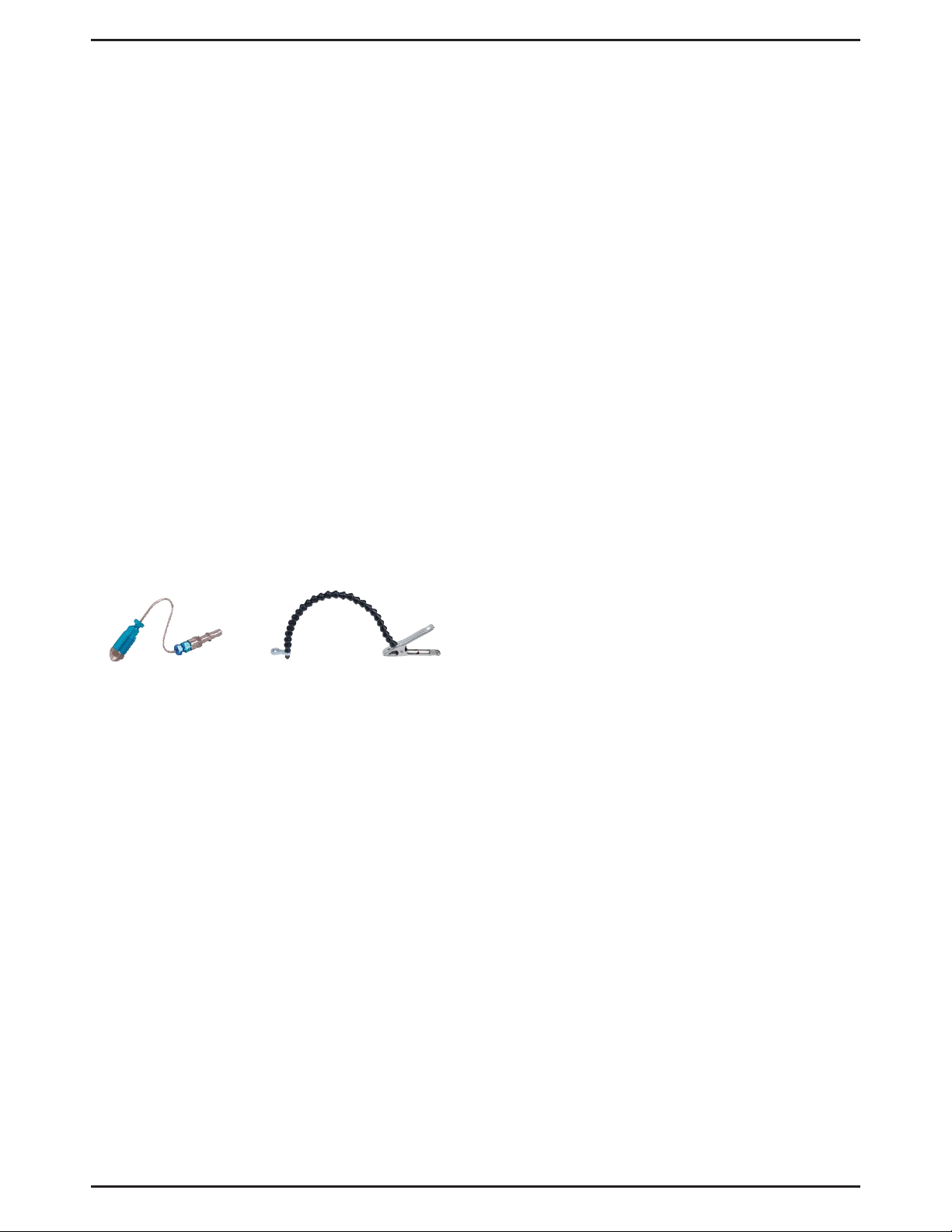
MVA550 - Decarb Nozzle
MVA551 – Extended Nozzle Clamp
Application Precautions
This equipment is intended for use by vehicle
service professionals with experience and knowledge of its application and limitations. While it is
designed for servicing a variety of vehicles in a
safe and convenient manner, due to variations
between vehicle manufacturers, makes, models
and years, use of this equipment is not always
feasible, possible, or recommended.
Use common sense when operating this equipment. If something does not seem or feel right,
stop immediately and consult a professional with
knowledge of the application. Don’t force the use
of this equipment on an application for which it is
not intended.
The procedures documented in this manual
are to serve as guidelines for general use of
this equipment. In addition to these guidelines,
always follow the vehicle manufacturer’s recommended procedures when attempting to use this
equipment.
When installing this equipment for induction
system cleaning, insure the cleaning solution is
introduced downstream from the mass airflow
sensor. Installing the nozzle upstream of the sensor can cause permanent damage to the sensor.
Harsh cleaning solutions can damage some
delicate idle air control valves. If unsure of the
effect of the cleaning solution on the IAC for the
vehicle, consult the vehicle’s manufacturer for
further information.
When performing a fuel injector cleaning service,
keep the Cleaner pressure below the rated fuel
pressure of the vehicle to prevent damage to the
injectors, and to prevent cleaning solution from
bypassing the regulator and entering the fuel
tank.
Safety Precautions
• Carefully read and understand these
instructions prior to using this equipment
• Always wear safety glasses when using this
equipment
• Avoid burns by remaining cautious of engine
parts that may become hot when the engine
is running
• Operate the vehicle only in a well ventilated
area, and away from potential sources of
flame or ignition
• Prior to starting an engine, make sure all
components of the tester, body parts, and
personal clothing are clear of rotating engine
components.
• Never leave a vehicle unattended during the
cleaning process.
• Check and secure all fuel system connections before starting the vehicle or pressurizing the system.
• Always keep a fire extinguisher on hand
when performing fuel related procedures.
Make sure the extinguisher is rated for fuel,
electrical, and chemical fires.
• Protect painted surfaces from fuel and
cleaning solutions.
• Release fuel system pressure before
servicing or disconnecting any fuel system
related components.
• This system is designed for use on gasoline
systems only.
Form 801817 Page Number - 3
Page 4

Components, Service Parts, and Accessories
The Mityvac Fuel Injection Cleaner operates using standard
shop air between 90 and 150 PSI (6 and 10 bar). To perform
a fuel injector cleaning service, a hose and adapter are required to connect to the engine’s fuel delivery system.
A connection hose and spray nozzle are required to perform
an air induction cleaning service.
Following is a list of standard components, service parts, and
accessories. All are available through you authorized Mityvac
dealer.
Standard Kit Components
Model MV5570 includes the following high quality
components:
• Manifold Assembly
0 to 150 PSI (0 to 10 bar) pressure gauge
Adjustable pressure regulator
Air inlet nipple
Inlet valve
Outlet valve
Supply hose adapter
• Fluid canister
• Wall mount bracket
• User’s manual (English, French, Spanish)
Model MV5565 includes the following high quality
components:
• Manifold Assembly
0 to 150 PSI (0 to 10 bar) pressure gauge
Adjustable pressure regulator
Air inlet nipple
Inlet valve
Outlet valve
Supply hose adapter
• Fluid canister
• Supply Hose
• Wall mount bracket
• User’s manual (English, French, Spanish)
Page Number - 4 Form 801817
Page 5

Service Parts & Accessories
Part Number Description
1 801832 Canister
2 801831 Pick-up Tube & Filter Assy
3 801825 Hook & Chain Assembly
4 801828 Air Inlet & Valve Assembly
5 801827 Pressure Regulator
6 801833 Replacement Gasket
7 801830 Relief Valve
8 801826 Pressure Gauge
9 801829 Outlet Valve Assy
801834 – Wall Mount Bracket
824147 – Connection Hose
9
8
6
3
7
5
4
1
MVA550 - Decarb Nozzle
MVA551 – Extended Nozzle Clamp
Form 801817 Page Number - 5
2
Page 6
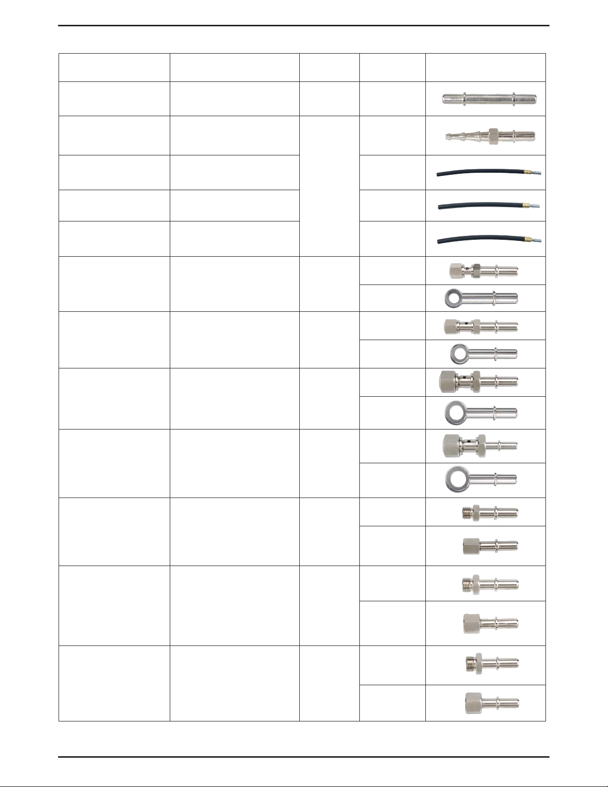
Fuel Injection Adapters
Description Applications Order No.
3/8" Quick-change
Adapter
1/4" - 3/8" Barbed
Flex Hose Adapter
1/4" Flex Hose
Adapter
5/16" Flex Hose
Adapter
3/8" Flex Hose
Adapter
M8 x 1.0
Banjo Adapter
M10 x 1.0
Banjo Adapter
GM, Chrysler, Jeep/Eagle MVA512 1
Vehicles with 1/4", 5/16" or
3/8" rubber to steel
hose connection
Vehicles with 1/4" rubber
to steel hose connection
Vehicles with 5/16" rubber
to steel hose connection
Vehicles with 3/8" rubber
to steel hose connection
Toyota MVA530
Toyota MVA531
MVA505
Reference
No.
16
16A
16B
13B
13C
14B
14C
M12 x 1.25
Banjo Adapter
M14 x 1.5
Banjo Adapter
M12 x 1.5
Ball Nose Adapter
M14 x 1.5
Ball Nose Adapter
M16 x 1.5
Ball Nose Adapter
Toyota, Lexus, Geo,
Honda, Acura, Hyundai,
Mazda, Daihatsu, Chrysler
imports
European vehicles
with CIS fuel system
European vehicles
with CIS fuel system
European vehicles
with CIS fuel system
15B
MVA532
15C
23A
MVA533
23C
12A
MVA517
12B
10A
MVA518
10B
11A
MVA519
11B
Page Number - 6 Form 801817
Page 7
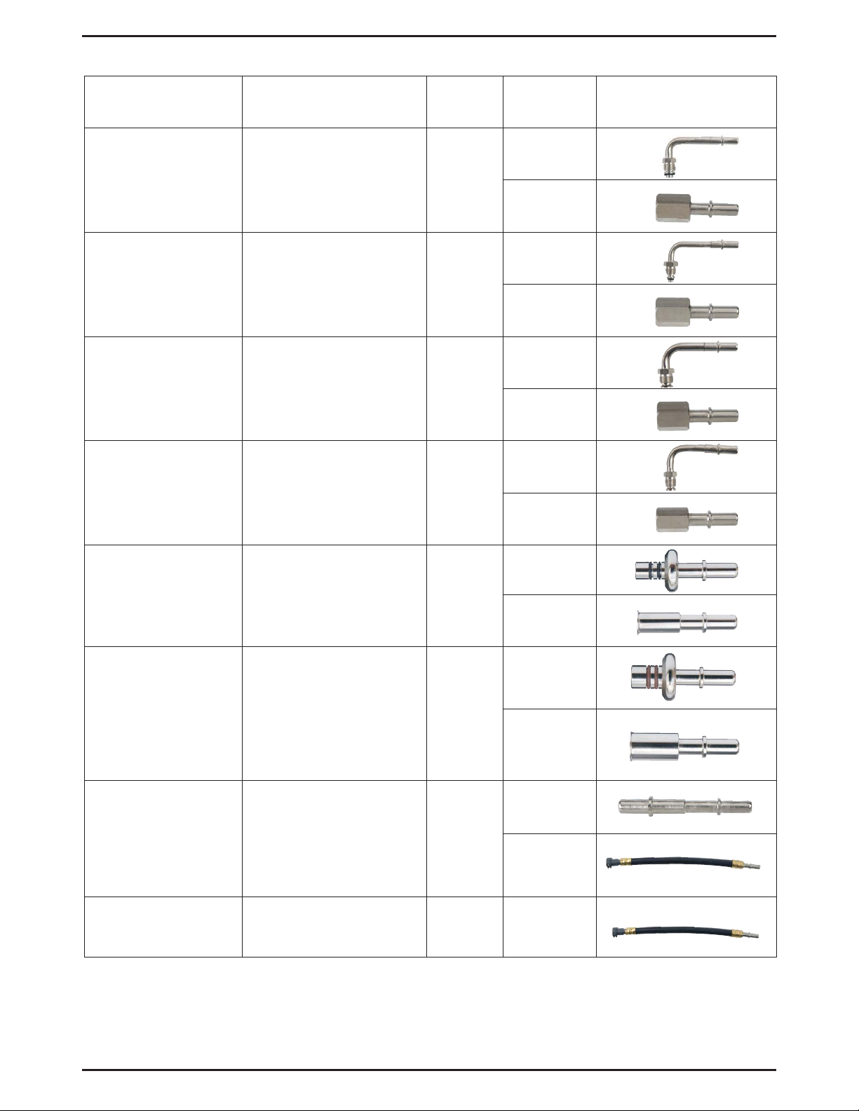
Fuel Injection Adapters
Description Applications Order No.
M16 x 1.5 Adapter GM Vortec MVA520
M14 x 1.5 Adapter GM Vortec MVA521
3/8" Flare Nut Adapter
5/16" Flare Nut
Adapter
Carbureted & early
fuel injected systems
Carbureted & early
fuel injected systems
MVA522
MVA523
Reference
No.
3A
3B
4A
4B
6A
6B
5A
5B
3/8" Spring Lock
Adapter
1/2" Spring Lock
Adapter
5/16" Quick-Change
Adapter
10mm Quick-Change
Adapter
7A
Ford fuel injection systems MVA524
7B
8A
Ford fuel injection systems MVA525
8B
2B
GM, Chrysler, Jeep/Eagle MVA526
2A
Diesel MVA534 24
Form 801817 Page Number - 7
Page 8

Proper Use, Care and Servicing
With proper care and maintenance, the Fuel Injection Cleaner
will provide years of reliable service.
The Fuel Injection Cleaner is designed for cleaning modern
fuel delivery systems on vehicles equipped with gasoline
powered combustion engines.
• After use, always empty and drain any remaining cleaning
solution from the Cleaner before storage.
• Always store the Cleaner in an upright position, in an
open environment and away from extreme heat and open
flames. We recommend hanging it with the wall mount
bracket included with the kit.
• Inspect components regularly for damage, and replace or
repair as necessary:
- Check hoses for cracks and cuts
- Check adapters for damage and wear to threads and
sealing surfaces
- Check female quick-connects for wear and cuts
to o-rings
• After installing the Cleaner and pressurizing the system,
check the Cleaner Assembly for leaks. If any leaks are
evident, immediately relieve the pressure, disconnect the
Cleaner, and send it to an authorized service center for
repair.
• The Cleaner has a sintered bronze filter element at the
end of the fluid pickup tube that extends into the canister.
This filter may be removed and cleaned with a solvent.
Ensure the filter is rid of all solvent before replacing.
Cleaning Solutions
The use of the Mityvac Fuel Injection Cleaner requires the
separate purchase of cleaning solution(s) specially formulated
for fuel injector or induction system cleaning using a canister
style cleaner. We recommend use of the following solutions:
OTC Part #7000A INJECT-R KLEEN
OTC Part #7904 D-KARBONIZER
BG Part #211 ISC Induction System Cleaner
BG Part #206 Air Intake System Cleaner
BG Part #210 Fuel Injection System Cleaner
Check the specifications for the cleaning solution prior to
use. Ensure it is specified for use with canister-style cleaning
systems, and is formulated for the type of cleaning service to
be performed.
WARNING
Fuel tank additives are not formulated for use in the
Mityvac Fuel Injection Cleaner.
Page Number - 8 Form 801817
Page 9
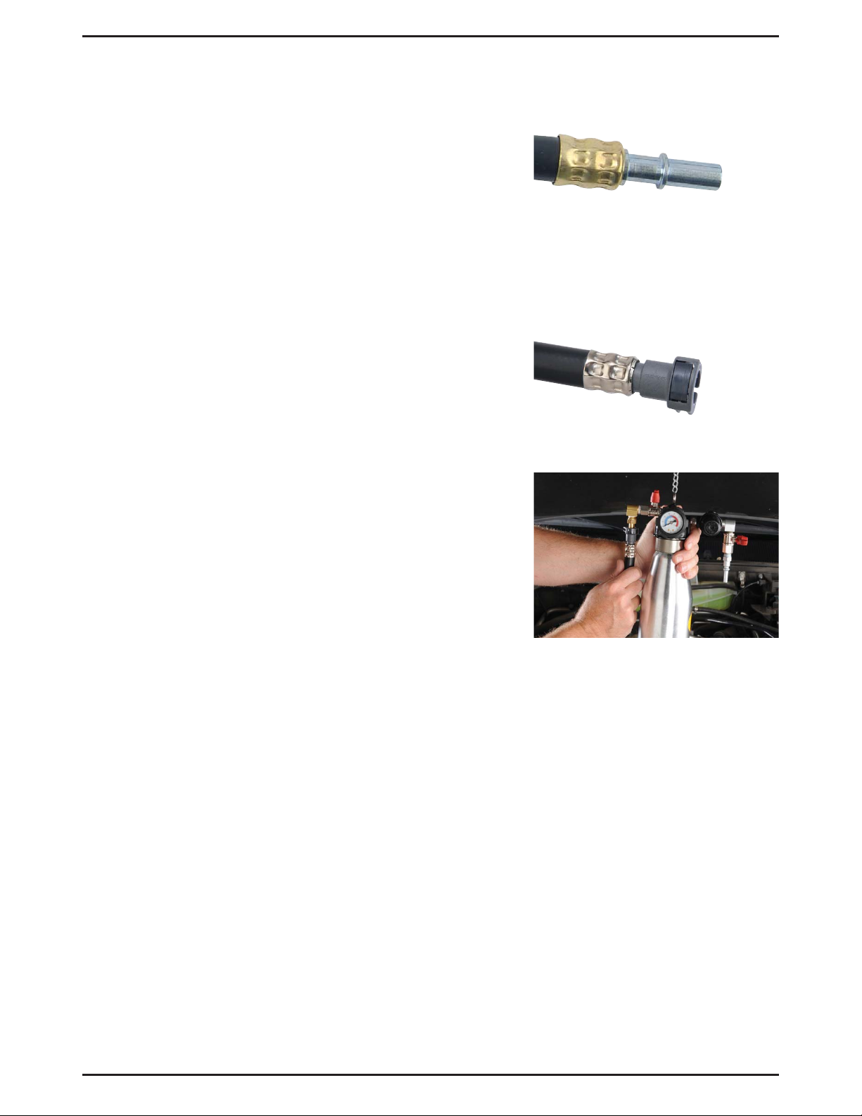
Connections
The outlet port of the fuel injection cleaner utilizes a special
male quick-connect fitting (Fig. 1). This fitting was selected
for several important reasons;
1. It conforms to the SAE J2044 specification for fuel fittings
2. It is a common fuel delivery system connection on which
many manufacturers are standardizing
3. It does not restrict fuel flow
4. The female quick-connect on the mating connection
hose, releases with a simple push-button action. No
special tools are required to disconnect the fittings.
The mating connection hose as well as the adapters and
fittings that connect the Cleaner into the fuel delivery system
utilize the same SAE J2044 endform (Fig. 2).
To secure the male to female connection, simply push the
male endform into the female quick-connect until it snaps
securely into place (Fig. 3). Always test the connection by
trying to pull it apart without pressing the release button.
Figure 1
Adapters
Mityvac offers a selection of adapters for connecting the
Cleaner to the fuel injection systems of a wide range of
automotive makes and models. The chart on pages 6 and 7
outlines the adapters available, and their applications. Each
adapter is etched with an identification number for easy
reference. Most of these adapters come standard with
the Mityvac FST. If you do not own an FST, they must be
purchased separately from an authorized Mityvac distributor.
Adapters can be purchased separately in sets according to
the order number indicated in the chart.
In most cases, selecting and installing adapters to the fuel injection system and connecting the Cleaner, is straightforward
and logical. Simply match the fuel system connection to the
equivalent adapter, and install it as outlined in the instructions
later in this manual.
Figure 2
Figure 3
Form 801817 Page Number - 9
Page 10

Set-up and Operation
Fuel Injector Cleaning
When performing fuel injector cleaning, the Cleaner should
be installed as close as possible to the inlet of the fuel rail.
On most vehicle models the fuel supply line can be disconnect directly from the end of the fuel rail, and the Cleaner
connected in its place. If not, the Cleaner can often be
connected just before the fuel rail at an alternate connection
such as a flexible rubber to steel hose connection or at the
outlet of the fuel filter.
1. Run the car until the engine is at operating temperature.
2. Place the vehicle transmission in park or neutral, apply
the parking brake, and turn off the key.
3. Unscrew the Fuel Injection Cleaner canister bottle from
the manifold assembly and pour in the appropriate fuel
injector cleaning solution.
4. Screw the canister back into the manifold assembly,
and hang the Cleaner under the vehicle’s hood using the
chain provided.
Figure 4
Figure 5
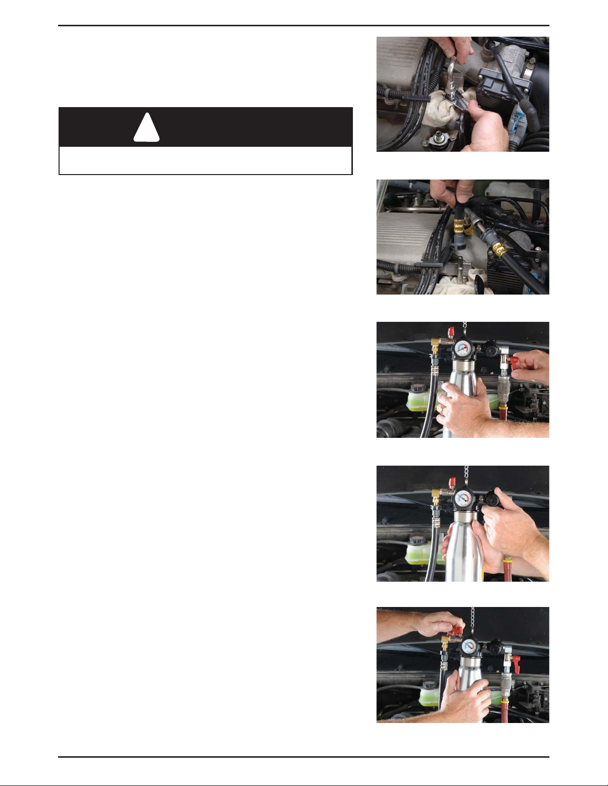
5. Close the Cleaner inlet and outlet valves.
6. Close the relief valve by turning it clockwise until tight.
7. Pull out on the regulator adjustment knob to unlock it,
and adjust the regulator to fully open by rotating the knob
counter-clockwise.
8. Connect the cleaner supply hose to the outlet of the
Cleaner (Fig. 4).
9. Connect shop air supply to the Cleaner inlet. Ensure the
shop air pressure is no greater than 150 psi (10 bar)
(Fig. 5).
10. Follow the vehicle manufacturer’s recommended proce-
dure to relieve the pressure from the vehicle fuel delivery
system.
11. If not done in the previous step, disable the fuel pump
by removing the fuse or relay, or unplugging it from the
power supply.
12. Locate the fuel supply line to the engine’s fuel rail, and
select the best location to disconnect the supply line and
install the hose extending from the Cleaner.
13. Remove or disconnect any obstacles required to gain
access to the connection, and place shop towels under
and around the connection to adsorb fuel from the
disconnected line.
Note: To minimize fuel spillage and reduce the amount
of time the fuel line is disconnected, try to identify the
type of connection before disconnecting the fuel line, and
have the required connection adapter readily available.
Page Number - 10 Form 801817
Page 11
14. Follow the vehicle manufacturer’s service information for
the proper method to disconnect the fuel line. Special
wrenches or disconnect tools may be required (Fig. 6).
Prop the loose end of the fuel supply line in a position to
prevent fuel from leaking out.
WARNING
Avoid spilling fuel on hot engine parts. Clean up any fuel
spills immediately after they occur.
15. Install the appropriate adapter to the fuel line running to
the fuel rail, or directly onto the fuel rail.
Note: If the fuel line connection used by the vehicle
manufacturer is a 3/8” quick-connect style (SAE J2044),
an adapter is not required (Fig. 7).
16. Connect the hose extending from the Cleaner to the
other end of the adapter.
17. Open the inlet valve located between the shop air
connection and the regulator (Fig. 8).
18. Slowly close the air regulator by turning the knob clock-
wise until the pressure gauge reads 5 psi (.3 bar) below
normal operating fuel pressure (Fig. 9).
The value for normal operating fuel pressure can be
located in a service guide or repair manual for the
specific vehicle.
19. Lock the regulator adjustment by pushing in on the knob.
Figure 6
Figure 7
20. Open the outlet valve between the canister and the hose
connection (Fig. 10).
21. Before proceeding:
a. Double check the connections. The Cleaner should
be installed such that the shop air enters the Cleaner,
and cleaning solution flows from the Cleaner into the
fuel rail.
b. Ensure the canister bottle is screwed securely into the
manifold, and is not cross-threaded.
c. Route the Cleaner and shop air hoses, and the
loose end of the fuel supply line away from rotating
engine components, belts, fans, and hot exhaust
components.
d. Remove the fuel spillage rags.
e. Reconnect components such as PCV tubes,
wiring harnesses, vacuum tubes, etc., that were
disconnected to gain access to the fuel line
connection.
Figure 8
Figure 9
Figure 10
Form 801817 Page Number - 11
Page 12
22. Start the engine and allow it to idle using the cleaning
solution inside the canister.
23. Run the engine until all the cleaning solution in the
canister has been used. This should take around
10 to 15 minutes.
Use wide-open-throttle blips two or three times during
this procedure to exercise the injectors and help clear
them of deposits.
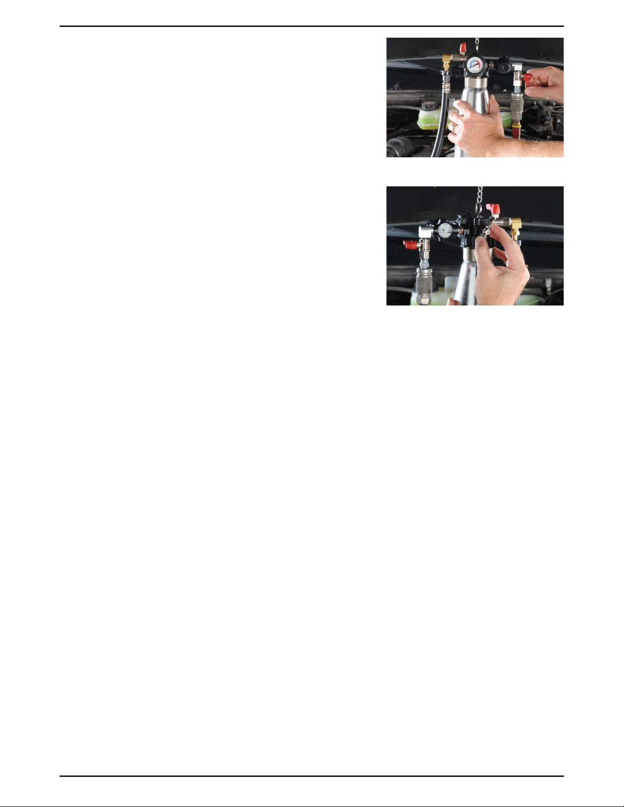
24. Once the cleaning solution has been used and the car
stalls, close the air inlet valve (Fig. 11).
25. Open the relief valve to release the system pressure
(Fig. 12).
26. Wrap a rag around the connection between the cleaner
hose and the vehicle’s fuel system, and disconnect the
hose.
27. Reconnect the vehicle fuel supply line and reactivate the
fuel pump.
28. Disconnect the air supply and cleaner hose from the
Cleaner. Properly dispose of any cleaning solution
remaining the bottle and hang the Cleaner on the wall
mount for storage.
Figure 11
Figure 12
Page Number - 12 Form 801817
Page 13
Intake System Decarbonizing
(requires MVA550 Decarb Nozzle, sold separately)
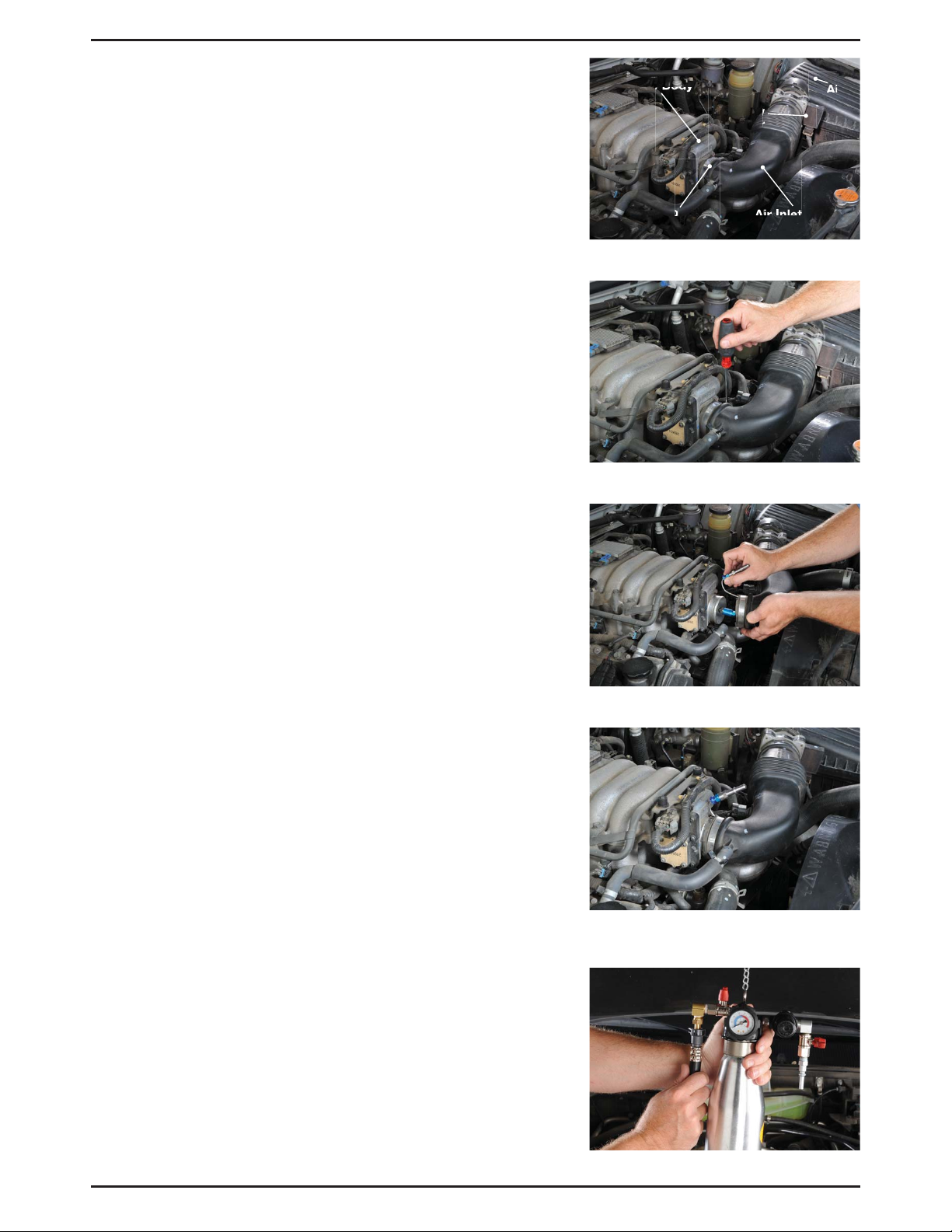
The Decarb Nozzle (MVA550) should be installed inside the
air intake duct, where it clamps to the inlet of the throttle
body. It must be installed downstream of the mass airflow
sensor (Fig. 13), so the cleaning solution does not come in
contact with the delicate sensor. In some cases, the mass
airflow sensor is mounted in the throttle body. Do not use the
Cleaner to perform air induction cleaning on this type of air
intake system.
The spray nozzle should point directly at the center of the
throttle plate without touching it. With the nozzle inserted into
the air stream, the small S-shaped steel tube should pass
between the air duct and the throttle body at the point where
the duct clamps onto the throttle body inlet. The supply hose
connection end of the nozzle assembly should extend outside
of the duct and the whole assembly held in place with the
worm clamp that secures the air duct to the throttle body. The
S-shaped steel tube can be bent into any shape required for
the installation.
1. Run the car until the engine is at operating temperature.
Throttle Body
Hose Clamp
Figure 13
Figure 14
Mass
Airflow
Sensor
Air Inlet Duct
Air
Filter
Inlet
2. Place the vehicle transmission in park or neutral, apply
the parking brake, and turn off the key.
3. Loosen the clamp securing the air intake duct to the inlet
of the throttle body (Fig. 14).
4. Slide the air intake duct off the throttle body and the
install the Decarb Nozzle so the spray nozzle end is
aimed at the center of the throttle plate, but not
touching it (Fig. 15).
5. With the nozzle pointed at the throttle plate, bend and
position the S-shaped steel tube so the air intake duct
can be slipped over it (Fig. 16).
6. Secure the adapter in place by tightening the hose
clamp. For additional support and to ensure the
Decarb Nozzle remains in the proper position, an
extended clamp, part no. MVA551 is available for
separate purchase. See page 3 for additional details.
7. Unscrew the Cleaner canister bottle from the manifold
assembly and pour in the appropriate decarbonizing
solution.
8. Screw the canister back into the manifold assembly,
and hang the Cleaner under the vehicle’s hood using the
chain provided.
Figure 15
Figure 16
9. Close the Cleaner inlet and outlet valves.
10. Close the relief valve by turning it clockwise until tight.
11. Pull out on the regulator adjustment knob to unlock it,
and adjust the regulator to fully open by rotating the knob
counter-clockwise.
Figure 17
Form 801817 Page Number - 13
Page 14
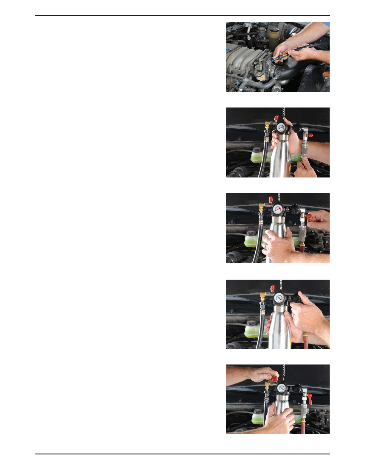
12. Connect one end of the Cleaner Hose to the outlet of
the Cleaner (Fig. 17), the other end to inlet of the Decarb
Adapter (Fig. 18).
13. Connect shop air supply to the Cleaner inlet. Ensure the
shop air pressure is no greater than 150 psi (10 bar)
(Fig. 19).
14. Start the vehicle and allow it to idle.
15. Return to the Cleaner and open the air inlet valve
(Fig. 20).
16. Rotate the regulator adjustment knob clockwise until the
pressure gauge reads approximately 60 psi (4 bar)
(Fig. 21).
17. Open the outlet valve to allow the cleaning solution to
spray into the air stream (Fig. 22).
At 60 psi (4 bar) pressure, it will take approximately
8 minutes to inject 12 oz (350 ml) of cleaning solution
into the air stream.
Figure 18
18. Close the air inlet valve when the canister is empty of
solution.
19. Turn off the car.
20. Allow the pressure to return to zero, and disconnect and
disassemble the Cleaner. Properly dispose of any unused
cleaning solution.
21. Remove the nozzle from the air induction system and
re-secure the air intake hose.
Note: Do not start the engine for 30 minutes. This will
allow the solution to soften and dissolve the carbon
deposits. After 30 minutes, test drive the vehicle for at
least 15 minutes to flush carbon deposits out of the
system.
Figure 19
Figure 20
Figure 21
Figure 22
Page Number - 14 Form 801817
Page 15

MANUAL DEL USUARIO
¿Tiene dudas técnicas?
América:
Si tiene dudas, o necesita servicio técnico,
póngase en contacto con nuestros técnicos
de servicio capacitados llamando al:
1-314-679-4200 ext. 4782
De lunes a viernes de 7:30 de la mañana a
las 4:15 de la tarde, hora del Centro. Visite
nuestro sitio web en www.mityvac.com para
ver nuevos productos, catálogos e instruccio-
nes de uso del producto.
LIMPIADOR DE INYECCIÓN
DE COMBUSTIBLE
MODELOS MV5570 Y MV556
¿Necesita piezas de servicio?
Para pedir piezas de repuesto o servicio,
visítenos en línea en www.mityvacparts.com
o llame al teléfono gratuito 1-800-992-9898.
Europa/África:
Heinrich-Hertz-Str 2-8
D-69183 Walldorf
Alemania
Teléfono +49.6227.33.0
Fax +49.6227.33.259
www.lincolnindustrial.de
Asia/Pacífico:
No. 3 Tampines Central 1
#04-05, Abacus Plaza.
Singapur 529540
Tel +65.6588.0188
Fax +65.6588.3438
El usuario de este equipo tiene la responsabilidad de leer este manual del usuario en su
totalidad, y entender el uso seguro y apropiado y la aplicación de este equipo.
MARZO - 2010 FORMULARIO 801817 Sección -
MV93-1B
Page 16

Índice
Introducción ...................................... 17
Precauciones de aplicación. . . . . . . . . . . . . . . . . . . . . . . . . . 17
Precauciones de seguridad ..........................17
Componentes, piezas de servicio y accesorios ........18
Piezas de servicio y accesorios ......................19
Adaptadores de inyección de combustible ............20
Uso, cuidado y servicio apropiados ..................22
Soluciones de limpieza .............................22
Conexiones ....................................... 23
Adaptadores ...................................... 23
Configuración y operación .......................... 24
Limpieza de los inyectores de combustible .............24
Descarbonización del sistema de admisión .............27
Francés .......................................... 29
Garantía ..........................................44
Número de página - 16 Formulario 801817
Page 17

Introducción
El limpiador de inyectores de combustible de
Mityvac puede efectuar dos tipos de servicios de
limpieza del motor:
1. Limpieza de inyectores de combustible
2. Limpieza del sistema de inducción de aire
La limpieza de inyectores de combustible se
efectúa instalando el limpiador directamente en
el sistema de suministro de combustible, donde
distribuye directamente una solución formulada
especialmente al motor. La solución disuelve los
depósitos de los inyectores e impide la acumulación futura.
La limpieza del sistema de inducción de aire se
efectúa introduciendo una boquilla (vendida por
separado) en la corriente del aire de admisión.
El limpiador suministra una solución de limpieza a la boquilla a presión, donde se inyecta
en la corriente de aire en forma de neblina fina.
La solución reviste el interior del cuerpo del
acelerador, el múltiple de admisión y las válvulas,
para desprender y disolver depósitos de carbón.
Los depósitos se queman después mediante la
combustión del motor.
Ambos tipos de servicios de limpieza pueden
mejorar el rendimiento del motor, disminuir el
consumo de combustible, reducir el mantenimiento y las emisiones.
MVA550
Boquilla de descarbonización
Abrazadera de boquilla extendida
MVA551
Precauciones de aplicación
Este equipo es para ser utilizado por profesionales de servicio de vehículos con experiencia y
conocimientos de su aplicación y sus limitaciones. Aunque está diseñado para servir una variedad de vehículos de manera segura y conveniente, debido a las variaciones entre los fabricantes
de vehículos, marcas, modelos y años, el uso
de este equipo no es siempre factible, posible o
recomendado.
Haga uso del sentido común al operar este
equipo. Si algo no parece o se cree que sea
adecuado, deténgase inmediatamente y consulte
con un profesional con conocimientos de la aplicación. No fuerce el uso de este equipo en una
aplicación para la que no está diseñado.
Los procedimientos documentados en este
manual son para servir como guías para el uso
general de este equipo. Además de estas guías,
siga siempre los procedimientos recomendados
por el fabricante del vehículo al tratar de usar
este equipo.
Al instalar este equipo para la limpieza del
sistema de inducción, asegúrese de que se introduzca la solución de limpieza aguas abajo del
sensor del gasto másico de aire. La instalación
de la boquilla aguas arriba del sensor puede
causar daños permanentes en el sensor.
Las soluciones de limpieza fuertes pueden dañar
algunas válvulas de control de aire en reposo.
Si no está seguro del efecto de la solución de
limpieza en el IAC el vehículo, consulte con el
fabricante del vehículo para obtener información
adicional.
Al efectuar un servicio de limpieza de inyectores de combustible, mantenga la presión del
limpiador por debajo de la presión nominal de
combustible del vehículo para impedir daños
en los inyectores, y que la solución de limpieza
ponga el regulador en derivación y entre en el
tanque de combustible.
Precauciones de seguridad
• Lea detenidamente y entienda estas instrucciones antes de usar este equipo
• Lleve siempre puestas gafas de seguridad al
usar este equipo
• Evite quemaduras teniendo cuidado de las
piezas del motor que puedan calentarse
cuando el motor esté en marcha
• Haga funcionar el vehículo sólo en un área
bien ventilada, y lejos de las fuentes potenciales de llamas o inflamación
• Antes de arrancar el motor, asegúrese de que
todos los componentes del probador, partes
del cuerpo y ropa personal estén alejados de
los componentes giratorios del motor.
• No salga nunca de un vehículo sin atender
durante el proceso de limpieza.
• Compruebe y fije todas las conexiones del
sistema de combustible antes de arrancar el
vehículo o someter el sistema a presión.
• Tenga siempre un extintor de incendios a
mano al efectuar procedimientos relacionados con el combustible. Asegúrese de que el
extintor tenga una capacidad nominal para
combustibles, sistemas eléctricos y fuegos
producidos por compuestos químicos.
• Proteja las superficies pintadas contra el
combustible y las soluciones de limpieza.
• Alivie la presión del sistema de combustible
antes de efectuar el servicio o desconectar
cualquier componente relacionado con el
sistema de combustible.
• Este sistema está diseñado para usar en
sistemas de gasolina solamente.
Formulario 801817 Número de página - 17
Page 18

Componentes, piezas de servicio y accesorios
El limpiador de inyección de combustible de Mityvac funciona usando aire comprimido estándar entre 90 y 150 lb/
pulg2 (6 y 10 bares). Para efectuar el servicio de limpieza
de los inyectores de combustible, se requiere conectar una
manguera y un adaptador al sistema de suministro de combustible del motor. Se requieren una manguera de conexión y
una boquilla de rociado para efectuar un servicio de limpieza
del sistema de inducción de aire.
A continuación se indica una lista de componentes estándar,
piezas de servicio y accesorios. Todos ellos están disponibles a través del distribuidor Mityvac autorizado.
Componentes del juego estándar
El modelo MV5570 incluye los siguientes componentes de
alta calidad:
• Conjunto de múltiple
2
Manómetro de 0 a 150 lb/pulg
Regulador de presión ajustable
Niple de entrada de aire
Válvula de entrada
Válvula de salida
Adaptador de la manguera de suministro
• Recipiente de fluido
• Soporte de montaje de pared
• Manual del usuario (inglés, francés, español)
(0 a 10 bares)
El modelo MV5565 incluye los siguientes componentes de
alta calidad:
• Conjunto de múltiple
2
Manómetro de 0 a 150 lb/pulg
(0 a 10 bares)
Regulador de presión ajustable
Niple de entrada de aire
Válvula de entrada
Válvula de salida
Adaptador de la manguera de suministro
• Recipiente de fluido
• Soporte de montaje de pared
• Manual del usuario (inglés, francés, español)
Número de página - 18 Formulario 801817
Page 19

Piezas y accesorios de servicio
Número de pieza Descripción
1 801832 Recipiente
2 801831 Conjunto de tubo de recogida y filtro
3 801825 Gancho y cadena
4 801828 Conjunto de entrada de aire y válvula
5 801827 Regulador de presió
6 801833 Empaquetadura de repuesto
7 801830 Válvula de alivio
8 801826 Manómetro
9 801829 Conjunto de válvula de salida
801834 – Soporte de montaje de pared
824147 – Manguera de conexión
9
8
6
3
7
5
4
1
MVA550 - Boquilla de descarbonización
MVA551 – Abrazadera de boquilla extendida
Formulario 801817 Número de página - 19
2
Page 20

Adaptadores de inyección de combustible
Descripción Aplicaciones
Adaptador de cambio
rápido de 3⁄8"
Adaptador de
manguera flexible bar-
bado de 1⁄4" - 3⁄8"
Adaptador de
manguera flexible de
1⁄4"
Adaptador de
manguera flexible de
5/16"
Adaptador de
manguera flexible de
3/8"
Adaptador banjo M8
x 1.0
Adaptador banjo M10
x 1.0
GM, Chrysler, Jeep/Eagle MVA512 1
Vehículos con conexión
de manguera de caucho a
acero de 1⁄4", 5⁄ 16" ó 3/8"
Vehículos con conexión
de manguera de caucho a
acero de 1⁄4"
Vehículos con conexión
de manguera de caucho a
acero de 5⁄ 16"
Vehículos con conexión
de manguera de caucho a
acero de 3⁄ 8"
No. de
pedido
MVA505*
Toyota MVA530
Toyota MVA531
No. de
referencia.
16
16A
16B
16C
13B
13C
14B
14C
Adaptador banjo M12
x 1.25
Adaptador banjo M12
x 1.5
Adaptador de punta
esférica
M12 x 1.5
Adaptador de punta
esférica
M14 x 1.5
Adaptador de punta
esférica
M16 x 1.5
Vehículos de importación
de Toyota, Lexus, Geo,
Honda, Acura, Hyundai,
Mazda, Daihatsu, Chrysler
Audi, Volkswagen MVA533
Vehículos europeos con
sistema de combustible
CIS
Vehículos europeos con
sistema de combustible
CIS
Vehículos europeos con
sistema de combustible
CIS
15B
MVA532
15C
23A
23C
12A
MVA517
12B
10A
MVA518
10B
11A
MVA519
11B
Número de página - 20 Formulario 801817
Page 21

Adaptadores de inyección de combustible
Descripción Aplicaciones
Adaptador M16 x 1.5 GM Vortec MVA520
Adaptador M14 x 1.25 GM Vortec MVA521
Sistemas de carburación y
Adaptador de tuerca
ensanchada de 3⁄8"
Adaptador de tuerca
ensanchada de 5⁄16"
primeros sistemas de
inyección
de combustible
Sistemas de carburación y
primeros sistemas de
inyección
de combustible
No. de
pedido
MVA522
MVA523
No. de
referencia
3A
3B
4A
4B
6A
6B
5A
5B
Adaptador de cierre
de muelle de 3⁄8"
Adaptador de cierre
de muelle de 1⁄2"
Adaptador de cambio
rápido de 5⁄16"
Adaptador de
cambio rápido
de 10mm
Sistemas de inyección de
combustible Ford
Sistemas de inyección de
combustible Ford
GM, Chrysler, Jeep/Eagle MVA526
Diesel MVA534 24
MVA524
MVA525
7A
7B
8A
8B
2B
2A
Formulario 801817 Número de página - 21
Page 22

Uso, cuidado y servicio apropiados
Con un cuidado y un mantenimiento apropiados, el limpiador
de inyección de combustible proporcionará años de servicio
fiable.
El limpiador de inyección de combustible está diseñado para
limpiar sistemas de suministro de combustible modernos
en vehículos con motores de combustión impulsados por
gasolina.
• Después de usar, vacíe y drene siempre cualquier
solución de limpieza restante del limpiador antes de su
almacenamiento.
• Almacene siempre el limpiador en posición vertical, en un
entorno abierto y alejado del calor extremo y de las llamas. Recomendamos colgarlo con el soporte de montaje
de pared incluido con el juego.
• Inspeccione los componentes regularmente para ver si
están dañados, y reemplácelos o repárelos según sea
necesario:
- Compruebe las mangueras para ver si tienen rajaduras y
cortes
- Compruebe los adaptadores para ver si están dañados y si
hay desgaste en las roscas y en las superficies de sellado
- Compruebe las conexiones hembra rápidas para ver si hay
desgaste y cortes en las juntas tóricas.
• Después de instalar el limpiador y someter a presión el
sistema, compruebe el conjunto de limpiador para ver si
hay fugas. Si hay fugas evidentes, alivie inmediatamente
la presión, desconecte el limpiador y envíelo a un centro
de servicio autorizado para su reparación.
• El limpiador tiene un elemento de filtro de bronce
sinterizado en el extremo del tubo de recogida que se
extiende dentro del recipiente. Este filtro puede quitarse
y limpiarse con disolvente. Asegúrese de que el filtro esté
libre de todo el disolvente antes de reemplazarlo.
Soluciones de limpieza
El uso de limpiador de inyección de combustible Mityvac
requiere la compra separada de soluciones de limpieza
especialmente formuladas para la limpieza del sistema de
inyectores de combustible o inducción usando un limpiador
estilo recipiente. Recomendamos el uso de las soluciones
siguientes:
OTC N° de pieza 7000A INJECT-R KLEEN
OTC N° de pieza 7904 D-KARBONIZER
BG N° de pieza 211 Limpiador de sistemas de inducción
ISC
BG N° de pieza 206 Limpiador de sistemas de admisión
de aire
BG N° de pieza 210 Limpiador de sistemas de inyección
de combustible
Compruebe las especificaciones de la solución de limpieza antes de usarla. Asegúrese de que esté especificada
para usar con sistemas de limpieza estilo recipiente, y esté
formulada para el tipo de servicio de limpieza que se vaya a
realizar.
Número de página - 22 Formulario 801817
ADVERTENCIA
Los aditivos de tanques de combustible no están formulados para ser
usados en el limpiador de inyección
de combustible Mityvac.
Page 23

Conexiones
El orificio de salida del limpiador de inyección de combustible utiliza un accesorio macho especial de conexión rápida
(Fig.1). Este accesorio fue seleccionado por diversas razones
importantes:
1. Cumple con la especificación SAE J2044 para acceso-
rios de combustible
2. Es una conexión de sistema de suministro de combus-
tible común que muchos fabricantes están normalizando
3. No restringe el paso de combustible
4. La conexión hembra rápida en la manguera de conexión
de acoplamiento, se desprende con una simple pulsación
de un botón. No se requieren herramientas especiales
para desconectar los accesorios.
La manguera de conexión de acoplamiento así como los
adaptadores y accesorios que conectan el limpiador con
el sistema de suministro de combustible utilizan el mismo
extremo SAE J2044 (Fig. 2).
Figura 1
Para fijar la conexión macho a la hembra, simplemente pulse
el extremo macho de la conexión hembra rápida hasta que
encaje bien a presión en posición (Fig. 3). Pruebe siempre
la conexión tratando de separarla tirando de la misma sin
apretar el botón de desprendimiento.
Adaptadores
Mityvac ofrece una selección de adaptadores para conectar
el limpiador a los sistemas de inyección de combustible de
una amplia gama de marcas y modelos de automóviles. La
tabla de las páginas 6 y 7 describe los adaptadores disponibles, y sus aplicaciones. Cada adaptador tiene grabado
un número de identificación como referencia sencilla. La
mayoría de estos adaptadores es estándar con el FST de
Mityvac. Si no posee su propio FST, debe comprarse por
separado de un distribuidor Mityvac autorizado. Los adaptadores pueden comprarse por separado en juegos según el
número de pedido indicado en la tabla.
En la mayoría de los casos, la selección e instalación de
adaptadores en el sistema de inyección de combustible y
la conexión del limpiador, es directa y lógica. Simplemente
haga corresponder la conexión del sistema de combustible
al adaptador equivalente, e instálelo según las instrucciones
descritas más adelante en este manual.
Figura 2
Figura 3
Formulario 801817 Número de página - 23
Page 24

Configuración y operación
Limpieza de inyectores de combustible
Al efectuar la limpieza de los inyectores de combustible, el
limpiador debe instalarse lo más cerca posible de la entrada
del riel de combustible. En la mayoría de los modelos de
vehículos la línea de suministro de combustible puede
desconectarse directamente del extremo del riel de combustible para conectar el limpiador en su lugar. Si no es así, a
menudo se puede conectar el limpiador justo antes del riel de
combustible en una conexión alternativa como una conexión
de manguera de goma flexible a acero o en la salida del filtro
de combustible.
1. Haga funcionar el automóvil hasta que el motor esté a la
temperatura de operación.
2. Coloque la transmisión del vehículo en estacionamiento
o punto muerto, conecte el freno de estacionamiento y
ponga la llave en apagado.
3. Desenrosque la botella del recipiente del limpiador de
inyección de combustible del conjunto de múltiple y eche
la solución de limpieza de inyectores de combustible
apropiada.
4. Vuelva a enroscar el recipiente en el conjunto de múltiple,
y cuelgue el limpiador debajo del capó del vehículo con
la cadena proporcionada.
5. Cierre las válvulas de entrada y salida del limpiador.
6. Cierre la válvula de alivio girándola hacia la derecha
hasta que quede apretada.
7. Tire de la perilla de ajuste del regulador para desblo-
quearla, y ajuste el regulador para abrirlo completamente
girando la perilla hacia la izquierda.
8. Conecte la manguera de suministro del limpiador a la
salida del limpiador (Fig. 4).
9. Conecte aire comprimido a la entrada del limpiador.
Asegúrese de que la presión de aire comprimido no sea
mayor que 150 lb/pulg2 (10 bares) (Fig. 5).
10. Siga el procedimiento recomendado del fabricante del
vehículo para aliviar la presión del sistema de suministro
de combustible del vehículo.
11. Si no se hace en el paso anterior, desactive la bomba de
combustible quitando el fusible o el relé, o desenchufándola de la fuente de alimentación.
12. Localice la línea de suministro de combustible en el riel
de combustible del motor, y seleccione la mejor ubicación para desconectar la línea de suministro e instalar
la manguera extendiéndose desde el limpiador.
13. Quite o desconecte cualquier obstáculo requerido para
obtener acceso a la conexión, y ponga toallas debajo y
alrededor de la conexión para absorber el combustible
de la línea desconectada.
Nota: Para reducir al mínimo el derrame de combus-
tible y reducir el tiempo de desconexión de la línea de
combustible, trate de identificar el tipo de conexión antes
de desconectar la línea de combustible, y disponga del
adaptador de conexión requerido.
Figura 4
Figura 5
Número de página - 24 Formulario 801817
Page 25

14. Siga en la información de servicio del fabricante del
vehículo el método apropiado para desconectar la línea
de combustible. Tal vez sea necesario usar llaves especiales o herramientas de desconexión (Fig. 6). Apoye el
extremo suelto de la línea de suministro de combustible
en una posición para impedir las fugas de combustible.
¡ADVERTENCIA!
No derrame combustible en piezas de motor calientes.
Limpie los derrames de combustible inmediatamente
después de que ocurran.
15. Instale el adaptador apropiado en la línea de combustible
que va al riel de combustible, o directamente sobre el riel
de combustible.
Nota: Si la conexión de la línea de combustible usada
por el fabricante del vehículo es de estilo de conexión
rápida de 3/8” (SAE J2044), no es necesario un
adaptador (Fig. 7).
16. Conecte la manguera que se extiende del limpiador al
otro extremo del adaptador.
17. Abra la válvula de entrada ubicada entre la conexión de
aire comprimido y el regulador (Fig. 8).
18. Cierre lentamente el regulador de aire girando la perilla
hacia la derecha hasta que el manómetro indique 5 lb/
pulg2 (0.3 bares) por debajo de la presión de combustible de operación normal (Fig. 9).
El valor de la presión de combustible de operación nor-
mal puede encontrarse en una guía de servicio o manual
de reparación para el vehículo específico.
19. Trabe el ajuste del regulador empujando la perilla.
20. Abra la válvula de salida entre el recipiente y la conexión
de la manguera (Fig. 10).
21. Antes de seguir adelante:
Figura 6
Figura 7
Figura 8
a. Asegúrese de que las conexiones estén apretadas.
El limpiador debe instalarse de modo que el aire
comprimido entre en el mismo, y la solución de
limpieza pase del limpiador al riel de combustible.
b. Asegúrese de que la botella del recipiente esté bien
enroscada en el múltiple, y que la rosca no esté
desgastada.
c. Tienda las mangueras del limpiador y de aire
comprimido, y el extremo suelto de la línea de
suministro de combustible lejos de los componentes
giratorios del motor, correa, ventiladores y
componentes de escape calientes.
d. Retire los trapos de derrame de combustible.
e. Reconecte los componentes como tubos de PCV,
mazos de cables, tubos de vacío, etc., que se
desconectaron para tener acceso a la conexión
de la línea de combustible.
Formulario 801817 Número de página - 25
Figura 9
Figura 10
Page 26

22. Arranque el motor y deje que funcione al ralentí usando
una solución de limpieza dentro del recipiente.
23. Haga funcionar el motor hasta que se haya usado toda
la solución de limpieza en el recipiente. Esto debe tardar
unos 10 a 15 minutos.
Abra el acelerador completamente dos o tres veces
durante este procedimiento para accionar los inyectores
y contribuir a eliminar los depósitos.
24. Una vez que se haya usado la solución de limpieza y se
cale el automóvil, cierre la válvula de entrada de aire
(Fig. 11).
25. Abra la válvula de alivio para aliviar la presión de sistema
(Fig. 12).
26. Enrolle un trapo alrededor de la conexión entre la
manguera del limpiador y el sistema del vehículo, y
desconecte la manguera.
27. Vuelva a conectar la línea de suministro del vehículo y
reactive la bomba de combustible.
28. Desconecte del limpiador las mangueras de suministro
de aire y del limpiador. Deseche debidamente el resto de
la solución de limpieza de la botella y cuelgue el limpia-
dor en el montaje de pared para su almacenamiento.
Figura 11
Figura 12
Número de página - 26 Formulario 801817
Page 27

Descarbonización del sistema de admisión
(requiere la boquilla de descarbonización MVA550,
vendida por separado)
La boquilla de descarbonización (MVA550) debe instalarse
en el interior del conducto de admisión de aire, donde se
sujeta a la entrada del cuerpo del acelerador. Debe instalarse
aguas abajo del sensor de gasto másico de aire (Fig. 13), de
modo que la solución de limpieza no se ponga en contacto
con el delicado sensor. En algunos casos, el sensor de gasto
másico de aire está montado en el cuerpo del acelerador.
No use el limpiador para efectuar la limpieza del sistema de
inducción de aire en este tipo de sistema de admisión de aire.
La boquilla de rociado debe apuntar directamente al centro
de la placa del acelerador sin tocarla. Una vez introducida
la boquilla en la corriente de aire, el pequeño tubo de acero
en forma de “S” debe pasar entre el conducto de aire y el
cuerpo del acelerador en el punto donde el conducto se
sujeta a la entrada del cuerpo del acelerador. El extremo de
la conexión de la manguera de suministro del conjunto de
boquilla debe extenderse hacia afuera del conducto y el conjunto completo debe mantenerse en posición con la abrazadera helicoidal que sujeta el conducto de aire al cuerpo del
acelerador. El tubo de acero en forma de “S” puede doblarse
adoptando cualquier forma requerida para la instalación.
Cuerpo del acelerador
Abrazadera
de manguera
Figura 13
Figura 14
Sensor
de gasto
másico
de aire
Conducto de
entrada de aire
Entrada
del filtro
de aire
1. Haga funcionar el automóvil hasta que el motor esté a la
temperatura de operación.
2. Ponga la transmisión del vehículo en estacionamiento
o punto muerto, conecte el freno de estacionamiento y
ponga la llave en apagado.
3. Afloje la abrazadera que sujeta el conducto de admisión
de aire a la entrada del cuerpo del acelerador (Fig. 14).
4. Deslice el conducto de admisión de aire fuera del cuerpo
del acelerador e instale la boquilla de descarbonización
de modo que el extremo de la boquilla de rociado apunte
al centro de la placa del acelerador, pero sin tocarla
(Fig. 15).
5. Con la boquilla apuntada a la placa del acelerador, doble
y coloque el tubo de acero en forma de “S” de modo que
el conducto de admisión de aire puede deslizarse sobre
la misma (Fig. 16).
6. Fije el adaptador en posición apretando la abrazadera
de la manguera. Para obtener un soporte adicional y
asegurarse de que la boquilla de descarbonización
permanezca en la posición apropiada, se dispone de
una abrazadera extendida, N° de pieza MVA551 que se
puede comprar por separado. Vea detalles adicionales
en la página 3.
Figura 1
Figura 16
7. Desenrosque la botella del recipiente del limpiador del
conjunto de múltiple y eche la solución de descarbon-
ización apropiada.
Figura 17
Formulario 801817 Número de página - 27
Page 28

8. Vuelva a desenroscar el recipiente en el conjunto de
múltiple, y cuelgue el limpiador debajo del capó del
vehículo usando la cadena proporcionada.
9. Cierre las válvulas de entrada y salida del limpiador.
10. Cierre la válvula de alivio girándola hacia la derecha
hasta que esté ajustada.
11. Tire de la perilla de ajuste del regulador para desblo-
quearla, y ajuste el regulador a la posición completa-
mente abierta girando la perilla hacia la izquierda.
12. Conecte un extremo de la manguera del limpiador a la
salida del limpiador (Fig. 17) y el otro extremo a la en-
trada del adaptador de descarbonización (Fig. 18).
13. Conecte aire comprimido a la entrada del limpiador.
Asegúrese de que la presión del aire comprimido no sea
2
mayor que 150 lb/pulg
(10 bares) (Fig. 19).
14. Arranque el vehículo y hágalo funcionar al ralentí.
15. Vuelva al limpiador y abra la válvula de entrada de aire
(Fig. 20).
16. Gire la perilla de ajuste del regulador hacia la derecha
hasta que el manómetro indique aproximadamente 60 lb/
2
(4 bares) (Fig. 21).
pulg
Figura 18
Figura 19
17. Abra la válvula de salida para dejar que la solución de
limpieza se rocíe en la corriente de aire (Fig. 22).
2
A una presión de 60 lb/pulg
(4 bares), se tardarán aproximadamente 8 minutos en inyectar 12 onzas (350 ml) de
solución de limpieza en la corriente de aire.
18. Cierre la válvula de entrada de aire cuando el recipiente
no tenga ninguna solución.
19. Apague el automóvil.
20. Deje que la presión vuelva a cero, y desconecte y desmonte el limpiador. Deseche debidamente la solución de
limpieza sin usar.
21. Quite la boquilla del sistema de inducción de aire y
vuelva a fijar la manguera de admisión de aire.
Nota: No arranque el motor durante 30 minutos. Esto
permitirá que la solución ablande y disuelva los depósitos de carbón. Después de 30 minutos, haga funcionar el
vehículo durante al menos 15 minutos para arrastrar los
depósitos de carbón fuera del sistema.
Figura 20
Figura 21
Figura 22
Número de página - 28 Formulario 801817
Page 29

MANUEL D’UTILISATION
Pour toute question technique :
Amériques :
En cas de questions ou de besoin
d’assistance technique, prière d’appeler nos
techniciens d’entretien spécialisés au :
1-314-679-4200, poste 4782
Lundi – vendredi, 7 heures 30 à 16 heures 15
(heure normale du centre des Etats-Unis)
Visiter notre site Web à www.mityvac.com
pour des nouveaux produits, catalogues et
instructions d’utilisation de nos produits.
NETTOYEUR D’INJECTEURS
MODÈLES MV5570 ET MV5565
Pour toute pièce de rechange :
Pour commander des pièces de rechange,
nous rendre visite en ligne à www.mityvacparts.com ou nous appeler sans frais au
1-800-992-9898.
Europe/Afrique :
Heinrich-Hertz-Str 2-8
D-69183 Walldorf
Deutschland
Téléphone +49.6227.33.0
Fax +49.6227.33.259
www.lincolnindustrial.de
Asie/Pacifique :
No. 3 Tampines Central 1
#04-05, Abacus Plaza.
Singapore 529540
Tel +65.6588.0188
Fax +65.6588.3438
Il incombe à l’utilisateur de ce matériel de lire le présent manuel en totalité et de veiller à bien
comprendre la façon correcte d’utiliser le matériel en toute sécurité.
MARS - 2010 DOCUMENT 801817 Section -
MV93-1B
Page 30

Table des matières
Introduction .......................................31
Précautions d’utilisation .............................31
Précautions de sécurité .............................31
Éléments, pièces de rechange et accessoires .........32
Pièces et accessoires ..............................33
Adaptateurs d’injecteurs ............................ 34
Emploi, entretien et réparation corrects ..............36
Solutions de nettoyage .............................36
Branchements ....................................37
Adaptateurs ....................................... 37
Installation et fonctionnement ....................... 38
Nettoyage des injecteur de carburant .................38
Décalaminage du système d’admission ................ 41
Espagnol ......................................... 15
Garantie ..........................................44
Page numéro - 30 Document 801817
Page 31

Introduction
Le nettoyeur d’injecteurs Mityvac peut permettre
d’effectuer le nettoyage de deux types d’organes
de moteur :
1. Nettoyage des injecteurs de carburant
2. Nettoyage du système d’admission d’air
Le nettoyage des injecteurs s’effectue en raccordant le nettoyeur directement au système
d’injection pour distribuer une solution spécialement préparée directement dans le moteur. Cette
solution dissout les dépôts présents dans les
injecteurs et empêche toute accumulation future.
Le nettoyage du système d’admission d’air
s’effectue en introduisant une buse (vendue
séparément) dans le passage d’air d’admission.
Le nettoyeur alimente en solution de nettoyage sous pression la buse qui l’injecte dans le
passage d’air sous forme de fines gouttelettes.
La solution se dépose à l’intérieur du corps de
papillon et de la tubulure d’admission, ainsi que
sur les soupapes pour décoller et dissoudre la
calamine. La calamine est ensuite brûlée par la
combustion dans le moteur.
Ces deux types de nettoyage peuvent rendre le
moteur plus performant, diminuer la consommation de carburant, limiter l’entretien et réduire
l’émission de gaz polluants.
MVA550
Buse de décalaminage
MVA551
Collier prolongé de buse
Précautions d’utilisation
Ce matériel est destiné aux professionnels expérimentés de l’entretien des véhicules qui sont
familiarisés avec son utilisation et ses limites.
Bien qu’il soit conçu pour l’entretien commode
de véhicules très divers en toute sécurité, il n’est
pas toujours possible ni recommandé de l’utiliser
par suite des différences qui existent entre les
constructeurs, marques, modèles et années de
fabrication.
Faire preuve de bon sens pour se servir de ce
matériel. Si quelque chose semble anormal,
s’arrêter immédiatement et consulter un professionnel familiarisé avec son utilisation. Ne pas
utiliser ce matériel pour un nettoyage auquel il
n’est pas destiné.
Il convient de considérer les méthodes décrites
dans ce manuel comme consignes d’utilisation
générale de ce matériel. Outre ces consignes,
toujours suivre les recommandations du
constructeur du véhicule pour se servir de ce
matériel.
Lors du raccordement de ce matériel pour le
nettoyage du système d’admission, veiller à ce
que la solution de nettoyage soit injectée en aval
du débitmètre d’air massique. Le débitmètre peut
être endommagé définitivement si la buse est
posée en amont de celui-ci.
Les solutions de nettoyage fortes peuvent
endommager certaines électrovalves régulatrices
d’air de ralenti délicates. En cas de doute quant à
l’effet de la solution de nettoyage sur la régulation de I’air de ralenti du véhicule, se renseigner
auprès du constructeur de celui-ci.
Lors d’un nettoyage d’injecteurs de carburant,
maintenir la pression du nettoyeur en dessous
de la pression nominale de carburant du véhicule
pour éviter d’endommager les injecteurs, ainsi
que pour empêcher la solution de nettoyage de
contourner le régulateur et de pénétrer dans le
réservoir de carburant.
Précautions de sécurité
• Lire attentivement ces instructions et veiller
à bien les comprendre avant d’utiliser ce
matériel
• Toujours porter des lunettes de protection
pour utiliser ce matériel
• Éviter de se brûler en faisant attention aux
pièces du moteur qui risquent de devenir très
chaudes quand celui-ci est en marche
• Ne faire tourner le moteur du véhicule que
dans un endroit bien aéré et à l’écart de
sources potentielles d’inflammation
• Avant de faire démarrer un moteur, veiller à
écarter tous les éléments du testeur, toute
partie du corps et les vêtements des organes
rotatifs du moteur.
• Ne jamais laisser un véhicule sans surveillance pendant le nettoyage.
• Vérifier et serrer tous les branchements du
circuit d’alimentation avant de faire démarrer
le moteur du véhicule ou de pressuriser le
circuit.
• Toujours garder un extincteur à portée de
la main lors d’opérations liées au carburant.
S’assurer que l’extincteur est homologué
pour les incendies de carburant, de produits
chimiques et d’origine électrique.
• Protéger les surfaces peintes du carburant et
des solutions de nettoyage.
• Dépressuriser le circuit d’alimentation avant
de réparer ou de débrancher tout élément lié
à ce circuit.
• Ce matériel est conçu pour être utilisé sur les
circuits d’alimentation en essence uniquement.
Document 801817 Page numéro - 31
Page 32

Éléments, pièces de rechange et accessoires
Le nettoyeur d’injecteurs Mityvac fonctionne à l’air comprimé
entre 6 et 10 bars (90 et 150 PSI). Un nettoyage d’injecteurs
exige un flexible et un adaptateur permettant le raccordement
au circuit d’alimentation du moteur.
Un nettoyage de l’admission d’air exige un flexible de raccordement et une buse.
Les éléments, pièces de rechange et accessoires standard
sont énumérés ci-après. Ils sont tous disponibles chez le
concessionnaire Mityvac agréé.
Éléments du kit standard
Le modèle MV5570 se compose des éléments de haute
qualité suivants :
• Collecteur
Manomètre gradué de 0 à 10 bars (0 à 150 PSI)
Régulateur de pression réglable
Manchon fileté d’entrée d’air
Vanne d’entrée
Vanne de refoulement
Adaptateur de flexible d’alimentation
• Nourrice de liquide
• Support de montage mural
• Manuel d’utilisation (anglais, français, espagnol)
Le modèle MV5565 se compose des éléments de haute
qualité suivants :
• Collecteur
Manomètre gradué de 0 à 10 bars (0 à 150 PSI)
Régulateur de pression réglable
Manchon fileté d’entrée d’air
Vanne d’entrée
Vanne de refoulement
Adaptateur de flexible d’alimentation
• Nourrice de liquide
• Flexible d’alimentation
• Support de montage mural
• Manuel d’utilisation (anglais, français, espagnol)
Page numéro - 32 Document 801817
Page 33

Pièces de rechange et accessoires
N° de pièce Description
1 801832 Nourrice
2 801831 Ensemble tube de captage / filtre
3 801825 Ensemble crochet / chaîne
4 801828 Ensemble entrée d’air / vanne
5 801827 Régulateur de pression
6 801833 Joint de rechange
7 801830 Détendeur de pression
8 801826 Manomètre
9 801829 Vanne de refoulement
801834 – Support de montage mural
824147 –Flexible de raccordement
9
8
6
3
7
5
4
1
MVA550 - Buse de décalaminage
MVA551 – Collier prolongé de buse
Document 801817 Page numéro - 33
2
Page 34

Adaptateurs d’injecteurs
Description Applications
Adaptateur 3⁄8 po
à rechange rapide
Adaptateur cannelé
1/4 - 3/8 po pour
flexible
Adaptateur 1⁄4 po
pour flexible
Adaptateur 5⁄16 po
pour flexible
Adaptateur 3⁄8 po
pour flexibler
Adaptateur banjo
M8 x 1,0
Adaptateur banjo
M10 x 1,0
GM, Chrysler, Jeep/Eagle MVA512 1
Véhicules à raccord 1/4,
5/16 ou 3/8 po caotchouc/
acier pour flexible
Véhicules à raccord 1/4 po
caoutchouc/acier pour
flexible
Véhicules avec raccord 5/16
po caoutchouc/acier pour
flexible
Véhicules à raccord 3/8 po
caoutchouc/ acier pour
flexible
Toyota MVA530
Toyota MVA531
N°
commande
MVA505
N° de
référence
16
16A
16B
16C
13B
13AC
14B
14C
Adaptateur banjo
M12 x 1,25
Adaptateur banjo
M14 x 1,5
Adaptateur à bout
sphérique
M12 x 1,5
Adaptateur à bout
sphérique
M14 x 1,5
Adaptateur à bout
sphérique
M16 x 1,5
Toyota, Lexus, Geo, Honda,
Acura, Hyundai, Mazda,
Daihatsu, Chrysler imports
d’importation
Véhicules européens à sys-
tème d’injection
continue de carburant
Véhicules européens à sys-
tème d’injection
continue de carburant
Véhicules européens
à système d’injection con-
tinue de carburant
15B
MVA532
15C
23A
MVA533
23C
12A
MVA517
12B
10A
MVA518
10B
11A
MVA519
11B
Page numéro - 34 Document 801817
Page 35

Adaptateurs d’injecteurs
Description Applications
Adaptateur
M16 x 1,5
Adaptateur
M14 x 1,5
Raccord conique
3⁄8 po
Systèmes à carburateurs
GM Vortec MVA520
GM Vortec MVA521
et d’injection anciens
N°
commande
MVA522
N° de
référence
3A
3B
4A
4B
6A
6B
Raccord conique
5⁄16 po
Adaptateur
verrouillable 3⁄8 po
Adaptateur
verrouillable 1⁄2 po
Adaptateur 5⁄16 po
à rechange rapide
Systèmes à carburateurs
et d’injection anciens
Systèmes d’injection
Ford
Systèmes d’injection
Ford
GM, Chrysler,
Jeep/Eagle
5A
MVA523
5B
7A
MVA524
7B
8A
MVA525
8B
2B
MVA526
2A
Adaptateur 10mm
à rechange rapide
Document 801817 Page numéro - 35
Diesel
MVA534 24
Page 36

Emploi, entretien et réparation corrects
S’il est entretenu correctement, le nettoyeur d’injecteurs of-
frira de nombreuses années de service sûr.
Le nettoyeur d’injecteurs est conçu pour le nettoyage des
circuits d’alimentation modernes équipant les véhicules à
moteur à essence.
• Après s’en être servi, toujours vider le nettoyeur de toute
solution de nettoyage qu’il contient encore avant de le
ranger.
• Toujours ranger le nettoyeur en position verticale, dans
un endroit dégagé à l’écart d’une chaleur intense et des
flammes nues. Nous recommandons de le suspendre à
l’aide du support de montage mural inclus dans le kit.
• Examiner régulièrement les éléments pour voir s’ils sont
endommagés et les remplacer ou les réparer selon le
besoin:
- Vérifier les flexibles pour voir s’ils sont fissurés ou cou-
pés
- Vérifier les adaptateurs pour voir si leur filetage et leurs
surfaces d’étanchéité sont endommagés ou usés
- Vérifier les raccords rapides femelles pour voir si leurs
joints toriques sont usés ou coupés
• Une fois le nettoyeur en place et pressurisé, contrôler
son étanchéité. S’il est évident qu’il fuit, le dépressuriser
immédiatement, le débrancher et le faire réparer par un
centre de réparation agréé.
• Le nettoyeur est pourvu d’un élément filtrant en bronze
fritté à l’extrémité du tube de captage de liquide qui se
prolonge jusque dans la nourrice. Il est possible de déposer ce filtre et de le nettoyer avec un solvant. S’assurer
qu’il ne reste plus de solvant dans le filtre avant de le
remettre en place.
Solutions de nettoyage
L’utilisation du nettoyeur d’injecteurs Mityvac exige l’achat
séparé d’une ou de plusieurs solutions de nettoyage
préparées spécialement pour le nettoyage des injecteurs de
carburant ou des systèmes d’admission à l’aide d’un nettoyeur du type à nourrice. Nous recommandons l’emploi des
solutions suivantes :
Pièce OTC n° 7000A, INJECT-R KLEEN
Pièce OTC n° 7904, D-KARBONIZER
Pièce BG n° 211, ISC - nettoyant pour système
d’admission
Pièce BG n° 206, nettoyant pour système d’admission
d’air
Pièce BG n° 210, nettoyant pour système d’injection de
carburant
Vérifier les caractéristiques de la solution de nettoyage avant
de s’en servir. S’assurer qu’elles sont adaptées à l’utilisation
avec les systèmes de nettoyage du type à nourrice et qu’elles
correspondent au type de nettoyage à effectuer.
Page numéro - 36 Document 801817
AVERTISSEMENT
Les additifs pour réservoirs de
carburant ne sont pas conçus
pour être utilisés dans le nettoyeur
d’injecteurs Mityvac.
Page 37

Branchements
L’orifice de refoulement du nettoyeur d’injecteurs utilise un
raccord rapide mâle spécial (Fig. 1). Ce raccord a été choisi
pour plusieurs raisons importantes :
1. Il est conforme à la spécification SAE J2044 applicable
aux raccords de carburant
2. Il s’agit d’un raccord couramment employé dans les
circuits d’alimentation, qui devient la norme pour de
nombreux constructeurs
3. Il ne gêne pas la circulation du carburant
4. Le raccord rapide femelle du flexible de raccordement
apparié se débloque par simple appui sur un boutonpoussoir. Le débranchement des raccords ne demande
aucun outil spécial.
Le flexible de raccordement apparié, ainsi que les adaptateurs et raccords qui relient le nettoyeur au circuit
d’alimentation, utilisent le même embout SAE J2044 (Fig. 2).
Figure 1
Pour assujettir le raccordement mâle-femelle, il suffit
d’enfoncer l’embout mâle dans le raccord rapide femelle
jusqu’à ce qu’il s’emboîte solidement en place (Fig. 3). Toujours contrôler le raccordement en essayant de le déboîter
sans appuyer sur le bouton de déblocage.
Adaptateurs
Mityvac offre un choix d’adaptateurs permettant de raccorder
le nettoyeur aux systèmes d’injection d’un large éventail de
marques et de modèles de véhicules automobiles. Le tableau
des pages 6 et 7 présente les adaptateurs disponibles et
leurs applications. Un numéro d’identification est gravé
dans chaque adaptateur auquel il est facile de se référer. La
plupart de ces adaptateurs sont fournis en standard avec le
testeur de circuit d’alimentation Mityvac. Si on ne dispose
pas d’un tel testeur, il est possible de se procurer ces adaptateurs séparément auprès d’un distributeur Mityvac agréé.
Des adaptateurs peuvent être achetés séparément en jeux en
se référant au numéro de commande indiqué dans le tableau.
Dans la plupart des cas, le choix des adaptateurs, leur
raccordement au système d’injection et le raccordement
au nettoyeur sont simples et logiques. Il suffit d’apparier le
raccord du circuit d’alimentation à l’adaptateur équivalent et
de mettre celui-ci en place conformément aux instructions
données plus loin dans ce manuel.
Figure 2
Figure 3
Document 801817 Page numéro - 37
Page 38

Installation et fonctionnement
Nettoyage des injecteurs
Lors du nettoyage d’injecteurs de carburant, installer le
nettoyeur aussi près que possible de l’entrée de la rampe
d’injection. Sur la plupart des modèles de véhicules, la
conduite d’alimentation en carburant peut être débranchée
directement de l’extrémité de la rampe d’injection et le nettoyeur raccordé à sa place. Sinon, le nettoyeur peut souvent
être raccordé juste avant la rampe d’injection au moyen d’un
dispositif de substitution tel qu’un raccord souple caoutchouc-acier ou à la sortie du filtre à carburant.
1. Faire tourner le moteur jusqu’à ce qu’il atteigne sa tem-
pérature de fonctionnement.
2. Placer la boîte de vitesses du véhicule en position de
stationnement ou au point mort, serrer le frein de stationnement et couper le contact.
3. Dévisser la nourrice du nettoyeur d’injecteurs du col-
lecteur et y verser la solution de nettoyage d’injecteurs
appropriée.
4. Revisser la nourrice dans le collecteur et suspendre
le nettoyeur sous le capot du véhicule au moyen de la
chaîne fournie.
5. Fermer les vannes d’entrée et de refoulement du net-
toyeur.
6. Fermer le détendeur de pression en le tournant à fond
dans le sens horaire.
7. Tirer sur le bouton de réglage du régulateur pour le
débloquer et régler le régulateur en position d’ouverture
complète en tournant le bouton dans le sens antihoraire.
8. Raccorder le flexible d’alimentation du nettoyeur à la
sortie de celui-ci (Fig. 4).
9. Raccorder l’arrivée d’air comprimé à l’entrée du net-
toyeur. S’assurer que la pression d’air ne dépasse pas 10
bars (150 psi) (Fig. 5).
10. Procéder comme le recommande le constructeur du
véhicule pour dépressuriser le circuit d’alimentation de
celui-ci.
11. Si cela n’a pas été fait lors de l’étape précédente, dés-
activer la pompe à carburant en enlevant le fusible ou
relais correspondant, ou en débranchant l’alimentation
électrique.
12. Repérer la conduite d’alimentation en carburant reliée
à la rampe d’injection du moteur et choisir le meilleur
endroit pour la débrancher puis raccorder le flexible
dépassant du nettoyeur.
13. Déposer ou débrancher toute pièce faisant obstacle pour
pouvoir accéder au branchement et placer des chiffons
en dessous et autour du branchement pour absorber le
carburant s’écoulant de la conduite débranchée.
Figure 4
Figure 5
Remarque : pour minimiser le renversement de carburant
et raccourcir la durée du débranchement de la conduite
de carburant, essayer d’identifier le type de raccordement avant de débrancher cette conduite et avoir
l’adaptateur de raccordement nécessaire à portée de la
main.
Page numéro - 38 Document 801817
Page 39

14. Appliquer les informations d’entretien du constructeur du
véhicule pour la méthode correcte de débranchement de
la conduite de carburant. Des clés ou outils de débranchement spéciaux peuvent s’avérer nécessaires (Fig. 6).
Soutenir l’extrémité débranchée de la conduite dans une
position qui empêchera du carburant de s’en écouler.
AVERTISSEMENT
Éviter de renverser du carburant sur les pièces chaudes du
moteur. Nettoyer tout déversement de carburant immédiatement après qu’il se produit.
15. Poser l’adaptateur approprié sur la conduite de carburant
reliée à la rampe d’injection ou directement sur celle-ci.
Remarque : si le raccord de conduite de carburant utilisé
par le constructeur du véhicule est un raccord rapide de
3/8 po (SAE J2044), un adaptateur n’est pas nécessaire
(Fig. 7).
16. Raccorder le flexible dépassant du nettoyeur à l’autre
côté de l’adaptateur.
17. Ouvrir la vanne d’entrée qui se trouve entre le branche-
ment d’air comprimé et le régulateur (Fig. 8).
18. Fermer lentement le régulateur de pression d’air en
tournant le bouton dans le sens horaire jusqu’à ce que le
manomètre indique 0,3 bar (5 psi) en dessous de la pression normale de service du carburant (Fig. 9).
On peut trouver la pression normale de service du carbu-
rant dans le guide d’entretien ou le manuel de réparation
du véhicule particulier.
19. Bloquer le régulateur dans la position à laquelle il a été
réglé en enfonçant le bouton.
20. Ouvrir la vanne de refoulement entre le réservoir et le rac-
cord du flexible (Fig. 10).
21. Avant de continuer :
a. Vérifier une nouvelle fois les branchements. Le
nettoyeur doit être installé de façon à ce que l’air
comprimé y pénètre et que la solution de nettoyage
circule du nettoyeur à la rampe d’injection.
b. S’assurer que la nourrice est bien vissée dans le
collecteur et qu’elle n’est pas faussée.
c. Faire passer les flexibles de nettoyeur et d’air
comprimé et placer l’extrémité débranchée de la
conduite d’alimentation en carburant à l’écart des
organes rotatifs du moteur, des courroies, des
ventilateurs et des pièces d’échappement chaudes.
d. Enlever les chiffons ayant recueilli le carburant
renversé.
e. Raccorder les éléments tels que tubes de recyclage
des gaz de carter, faisceaux de fils, tubes à
dépression, etc., qui ont été débranchés pour
accéder au raccord de conduite de carburant.
Figure 6
Figure 7
Figure 8
Figure 9
Figure 10
Document 801817 Page numéro - 39
Page 40

22. Faire démarrer le moteur et le laisser tourner au ralenti en
utilisant la solution de nettoyage contenue dans la nourrice.
23. Faire tourner le moteur jusqu’à ce que toute la solution
de nettoyage contenue dans la nourrice ait été utilisée,
ce qui devrait prendre 10 à 15 minutes environ.
Passer en pleins gaz deux ou trois fois dans le cours de
cette opération pour actionner les injecteurs et faciliter
leur décalaminage.
24. Une fois que la solution de nettoyage est épuisée et que
le moteur cale, fermer la vanne d’entrée d’air (Fig. 11).
25. Ouvrir le détendeur de pression pour dépressuriser le
nettoyeur (Fig. 12).
26. Enrouler un chiffon autour du branchement du flexible
du nettoyeur au circuit d’alimentation du véhicule et
débrancher le flexible.
27. Raccorder la conduite d’alimentation en carburant du
véhicule et réactiver la pompe à carburant.
28. Débrancher l’alimentation en air et le flexible de nettoyeur
de ce dernier. Mettre toute solution de nettoyage restant
dans la nourrice au rebut comme il convient et ranger le
nettoyeur sur le support mural.
Figure 11
Figure 12
Page numéro - 40 Document 801817
Page 41

Décalaminage du système d’admission
(exige une buse de décalaminage MVA550 vendue
séparément)
Mettre la buse de décalaminage (MVA550) en place à
l’intérieur du conduit d’admission d’air, où elle se fixe à
l’entrée du corps de papillon. Elle doit être posée en aval du
débitmètre d’air massique (Fig. 13), de façon à éviter tout
contact entre la solution de nettoyage et le délicat débitmètre.
Dans certains cas, le débitmètre d’air massique est monté
dans le corps de papillon. Ne pas se servir du nettoyeur pour
nettoyer un système d’admission d’air de ce type.
La buse doit être dirigée directement vers le centre du papillon, sans le toucher. La buse étant introduite dans le passage
d’air, le petit tube d’acier en forme de S doit passer entre le
conduit d’air et le corps de papillon au point où le conduit
se fixe à l’entrée du corps de papillon. Le côté de raccordement de flexible d’alimentation de la buse doit dépasser à
l’extérieur du conduit et l’ensemble être maintenu en place au
moyen du collier à vis sans fin fixant le conduit d’air au corps
de papillon. Il est possible de recourber le tube d’acier en
forme de S afin de lui donner toute forme nécessaire pour la
mise en place.
1. Faire tourner le moteur jusqu’à ce qu’il atteigne sa tem-
pérature de fonctionnement.
2. Placer la boîte de vitesses du véhicule en position de
stationnement ou au point mort, serrer le frein de stationnement et couper le contact.
3. Desserrer le collier fixant le conduit d’admission d’air à
l’entrée du corps de papillon (Fig. 14).
4. Faire glisser le conduit d’admission d’air pour le séparer
du corps de papillon et mettre la buse de décalaminage
en place de façon à ce que son embout soit dirigé vers le
centre du papillon sans le toucher (Fig. 15).
5. La buse étant orientée vers le papillon, recourber le tube
d’acier en forme de S et le positionner de façon à ce que
le conduit d’admission d’air puisse être glissé par-dessus
(Fig. 16).
6. Assujettir l’adaptateur en place en serrant le collier. Pour
un meilleur support et garantir que la buse de décalaminage reste dans la bonne position, on peut acheter un
collier prolongé (pièce n° MVA551). Pour plus de détails,
voir page 3.
7. Dévisser la nourrice du collecteur et y verser la solution
de décalaminage appropriée.
8. Revisser la nourrice dans le collecteur et suspendre
le nettoyeur sous le capot du véhicule au moyen de la
chaîne fournie.
9. Fermer les vannes d’entrée et de refoulement du nettoy-
eur.
10. Fermer le détendeur de pression en le tournant à fond
dans le sens horaire.
11. Tirer sur le bouton de réglage du régulateur pour le
débloquer et régler le régulateur en position d’ouverture
complète en tournant le bouton dans le sens antihoraire.
Corps de
papillon
Collier
Figure 13
Figure 14
Figure 15
Figure 16
Débitmètre
d’air
massique
Conduit
d’admission d’air
Entrée
de
filtre
à air
Figure 17
Document 801817 Page numéro - 41
Page 42

12. Raccorder une extrémité du flexible du nettoyeur à la sor-
tie de celui-ci (Fig. 17) et l’autre à l’entrée de l’adaptateur
de décalaminage (Fig. 18).
13. Raccorder l’arrivée d’air comprimé à l’entrée du net-
toyeur. S’assurer que la pression d’air ne dépasse pas 10
bars (150 psi) (Fig. 19).
14. Faire démarrer le moteur et le laisser tourner au ralenti.
15. Revenir au nettoyeur et ouvrir la vanne d’entrée d’air (Fig.
20).
16. Tourner le bouton de réglage du régulateur dans le sens
horaire jusqu’à ce que le manomètre indique 4 bars (60
psi) environ (Fig. 21).
17. Ouvrir la vanne de refoulement pour permettre la
pulvérisation de solution de nettoyage dans le passage
d’air (Fig. 22). À une pression de 4 bars (60 psi), il faut 8
minutes environ pour injecter 350 ml (12 oz) de solution
dans le passage.
Figure 18
18. Refermer la vanne d’entrée d’air quand la nourrice est
vide de solution.
19. Arrêter le moteur.
20. Laisser la pression revenir à zéro puis débrancher et
démonter le nettoyeur. Mettre toute solution de nettoyage
inutilisée au rebut comme il convient.
21. Retirer la buse du système d’admission d’air et assujettir
le flexible d’admission d’air.
Remarque : attendre 30 minutes pour faire démarrer le
moteur. Cela permet à la solution de décoller et de dissoudre la calamine. Au bout de 30 minutes, essayer le
véhicule pendant au moins 15 minutes pour expulser la
calamine du système
.
Figure 19
Figure 20
Figure 21
Figure 22
Page numéro - 42 Document 801817
Page 43

Document 801817 Page numéro - 43
Page 44

Lincoln Industrial Standard Warranty/ Garantía Estándar de Lincoln Industrial/ Garantie standard Lincoln Industrial
LIMITED WARRANTY
Lincoln warrants the equipment manufactured and supplied by Lincoln to be free from defects in material and workmanship for a period of one (1) year following the
date of purchase, excluding therefrom any special, extended, or limited warranty published by Lincoln. If equipment is determined to be defective during this warranty
period, it will be repaired or replaced, within Lincoln’s sole discretion, without charge.
This warranty is conditioned upon the determination of a Lincoln authorized representative that the equipment is defective. To obtain repair or replacement, you must
ship the equipment, transportation charges prepaid, with proof of purchase to a Lincoln Authorized Warranty and Service Center within the warranty period.
This warranty is extended to the original retail purchaser only. This warranty does not apply to equipment damaged from accident, overload, abuse, misuse, negligence,
faulty installation or abrasive or corrosive material, equipment that has been altered, or equipment repaired by anyone not authorized by Lincoln. This warranty applies
only to equipment installed, operated and maintained in strict accordance with the written specifications and recommendations provided by Lincoln or its authorized
field personnel.
THIS WARRANTY IS EXCLUSIVE AND IS IN LIEU OF ANY OTHER WARRANTIES, EXPRESSED OR IMPLIED, INCLUDING, BUT NOT LIMITED TO, THE WARRANTY
OF MERCHANTABILITY OR WARRANTY OF FITNESS FOR A PARTICULAR PURPOSE.
In no event shall Lincoln be liable for incidental or consequential damages. Lincoln’s liability for any claim for loss or damages arising out of the sale, resale or use of
any Lincoln equipment shall in no event exceed the purchase price. Some jurisdictions do not allow the exclusion or limitation of incidental or consequential damages,
therefore the above limitation or exclusion may not apply to you.
This warranty gives you specific legal rights. You may also have other rights that vary by jurisdiction.
Customers not located in the Western Hemisphere or East Asia: Please contact Lincoln GmbH & Co. KG, Walldorf, Germany, for your warranty rights.
Lincoln Industrial Contact Information:
To find Lincoln Industrial’s Nearest Service Center call the following numbers, or you may also use our web site.
Customer Service: 314-679-4200 Web site: lincolnindustrial.com
Americas:
One Lincoln Way
St. Louis, MO 63120-1578
USA
Phone +1.314.679.4200
Fax +1.800.424.5359
GARANTÍA LIMITADA
Lincoln garantiza que los equipos fabricados y suministrados por Lincoln carecen de defectos de material y mano de obra durante un periodo de un (1) año a partir de
la fecha de compra, excluyendo a partir de la misma cualquier garantía especial, ampliada o limitada publicada por Lincoln. Si se determina que un equipo tiene algún
defecto durante este periodo de garantía, será reparado o reemplazado, a discreción única de Lincoln, sin cargo alguno.
Esta garantía está condicionada a la determinación de un representante autorizado de Lincoln de que el equipo es defectuoso. Para su reparación o sustitución, usted
tiene que enviar el equipo, con los gastos de transporte pagados por anticipado y con una prueba de la compra, a un Centro de Servicio y Garantía Autorizado de
Lincoln dentro del periodo de garantía.
Esta garantía se extiende solo al comprador al por menor original. Esta garantía no se aplica a los equipos dañados a causa de un accidente, sobrecarga, abuso, uso
indebido, negligencia, instalación defectuosa o materiales abrasivos o corrosivos, equipos que hayan sido alterados, o equipos reparados por cualquier persona que
no haya sido autorizada por Lincoln. Esta garantía solo se aplica a los equipos instalados, operados y mantenidos en estricta conformidad con las especificaciones y
recomendaciones por escrito proporcionadas por Lincoln o su personal de campo autorizado.
ESTA GARANTÍA ES EXCLUSIVA Y ES EN LUGAR DE A CUALQUIER OTRA GARANTÍA, EXPRESA O IMPLÍCITA, INCLUIDAS, AUNQUE SIN LIMITARSE A LAS
MISMAS, LA GARANTÍA DE COMERCIABILIDAD O GARANTÍA DE IDONEIDAD PARA UN FIN PARTICULAR.
En ningún caso deberá ser responsable Lincoln de los daños fortuitos o emergentes. La responsabilidad de Lincoln por cualquier reclamación de pérdidas o daños que
surjan de la venta, reventa o utilización de cualquier equipo de Lincoln no deberá exceder en ningún caso el precio de compra. Algunas jurisdicciones no admiten las
exclusiones o limitaciones de los daños fortuitos o emergentes y, por lo tanto, puede que la anterior limitación o exclusión no se aplique a su caso.
Esta garantía le proporciona derechos legales específicos. Usted puede tener también otros derechos que varían de una jurisdicción a otra.
Los clientes no ubicados en el Hemisferio Occidental o el Este de Asia: pónganse en contacto con Lincoln GmbH & Co. KG, Walldorf, Alemania, para conocer sus
derechos de garantía.
Información de contacto de Lincoln Industrial:
Para buscar el Centro de Servicio Lincoln Industrial más cercano, llame a los siguientes números, o también puede visitar nuestro sitio web.
Atención al Cliente 314-679-4200 Sitio Web: lincolnindustrial.com
Américas:
One Lincoln Way
St. Louis, MO 63120-1578
EE.UU.
Teléfono +1.314.679.4200
Fax +1.800.424.5359
GARANTIE LIMITÉE
Lincoln garantit l'appareillage fabriqué et fourni par Lincoln contre les défauts de matières et de fabrication pendant une période d'un (1) an à compter de la date
d'achat, excluant toute autre garantie spéciale, prolongée ou limitée rendue publique par Lincoln. S’il est déterminé, dans les limites de cette période de garantie, que
l’appareillage est défectueux, il sera réparé ou remplacé gratuitement, à la seule discrétion de Lincoln.
Cette garantie est tributaire de la détermination par un représentant habilité de Lincoln que l'appareillage est défectueux. Pour être réparé ou remplacé, l’appareillage
doit être retourné en port payé accompagné d’une preuve d’achat à un centre de garantie et de réparation Lincoln agréé dans les limites de la période de garantie.
Cette garantie n’est offerte qu’à l’acheteur initial au détail. Cette garantie ne s’applique pas à un appareillage endommagé à la suite d’un accident, d’une surcharge,
d’un usage abusif ou incorrect, de la négligence, d’un raccordement incorrect, d’un contact avec un matériau abrasif ou corrosif, d'une modification ou d'une réparation
effectuée par quiconque n'est pas agréé par Lincoln. Cette garantie ne s’applique qu’à l’appareillage raccordé, utilisé et entretenu en stricte conformité avec les spécifications et recommandations communiquées par écrit par Lincoln ou son personnel technico-commercial habilité.
CETTE GARANTIE EXCLUT ET SE SUBSTITUE À TOUTE AUTRE GARANTIE EXPLICITE OU TACITE, Y COMPRIS, ENTRE AUTRES, CELLES DE QUALITÉ MARCHANDE ET D’ADAPTATION À UN USAGE PARTICULIER.
Lincoln ne sera en aucun cas responsable de dommages accessoires ou indirects. La responsabilité de Lincoln en cas de demande d’indemnisation pour pertes ou
dommages liés à la vente, revente ou utilisation de tout appareillage Lincoln n’ira en aucun cas au-delà du prix d'achat. Certaines collectivités territoriales n’autorisent
pas l’exclusion ni la limitation des dommages accessoires ou indirects. Il se peut donc que la limitation ou exclusion mentionnée ci-dessus ne s’applique pas. Cette garantir confère des droits précis. Il peut toutefois en exister d’autres qui varient d’une collectivité territoriale à l’autre. Les clients résidant hors de l’hémisphère occidental
ou de l’Asie orientale sont priés de se renseigner auprès de Lincoln GmbH & Co, Walldorf, Allemagne, sur les droits dont ils jouissent au titre de la garantie.
Coordonnées de Lincoln Industrial :
Pour localiser le centre de réparation de Lincoln Industrial le plus proche, appeler l'un des numéros ci-dessous ou utiliser notre site Web.
Service clientèle: 314-679-4200 Site Web : lincolnindustrial.com
Amériques :
One Lincoln Way
St. Louis, MO 63120-1578
USA
Téléphone +1.314.679.4200
Télécopie +1.800.424.5359
Europe/Africa:
Heinrich-Hertz-Str 2-8
D-69183 Walldorf
Germany
Phone +49.6227.33.0
Fax +49.6227.33.259
Europa/África:
Heinrich-Hertz-Str 2-8
D-69183 Walldorf
Alemania
Teléfono +49.6227.33.0
Fax +49.6227.33.259
Europe/Afrique :
Heinrich-Hertz-Str 2-8
D-69183 Walldorf
Allemagne
Téléphone +49.6227.33.0
Télécopie +49.6227.33.259
Asia/Pacific:
No. 3 Tampines Central 1
#04-05, Abacus Plaza.
Singapore 529540
Tel +65.6588.0188
Fax +65.6588.3438
Asia/Pacífico:
No. 3 Tampines Central 1
#04-05, Abacus Plaza.
Singapur 529540
Tel +65.6588.0188
Fax +65.6588.3438
Asie/Pacifique :
No. 3 Tampines Central 1
#04-05, Abacus Plaza.
Singapore 529540
Tel +65.6588.0188
Fax +65.6588.3438
© Copyright 2010 www.lincolnindustrial.com Printed in Taiwan
Page Number - 44 Form 801817
 Loading...