

Mityvac MV5545E User Manual
USER’S MANUAL
Have a technical question?
Americas:
If you have questions, or require technical
service, please contact our trained service
technicians at:
1-314-679-4200 ext. 4782
Monday – Friday 7:30 am to 4:15 pm CST
Visit our website at www.mityvac.com for
new products, catalogs, and instructions
for product use.
Need service parts?
To order replacement or service parts, visit us
online at www.mityvacparts.com or call toll free
1-800-992-9898.
Europe/Africa:
Heinrich-Hertz-Str 2-8
D-69183 Walldorf
Germany
Phone +49.6227.33.0
Fax +49.6227.33.259
www.lincolnindustrial.de
FST PRO FUEL SYSTEM TESTER
MODEL MV5545E
Asia/Pacific:
25 Int’l Business Park
#01-65 German Centre
Singapore 609916
Phone +65.562.7960
Fax +65.562.9967
For a French or Spanish version of this
manual go to www.MityvacFST.com.
APRIL - 2009 Form 824262 Section - MV92-1

Contents
Safety Precautions . . . . . . . . . . . . . . . . . . . . . . . . . . . . . . . . . . . . . . . . 3
Specifications . . . . . . . . . . . . . . . . . . . . . . . . . . . . . . . . . . . . . . . . . . . .3
Components, Service Parts, and Accessories . . . . . . . . . . . . . . . . 4
Standard Kit Components . . . . . . . . . . . . . . . . . . . . . . . . . . . . . . . . . . 4
Service Parts . . . . . . . . . . . . . . . . . . . . . . . . . . . . . . . . . . . . . . . . . . . .5
Fuel System Test Adapters . . . . . . . . . . . . . . . . . . . . . . . . . . . . . . . 6-7
Assembly . . . . . . . . . . . . . . . . . . . . . . . . . . . . . . . . . . . . . . . . . . . . . . . 8
Bypass Hose . . . . . . . . . . . . . . . . . . . . . . . . . . . . . . . . . . . . . . . . . . 8
Proper Use, Care, and Servicing . . . . . . . . . . . . . . . . . . . . . . . . . . . . 8
Setup and Installation . . . . . . . . . . . . . . . . . . . . . . . . . . . . . . . . . . . . . 9
Determining Where to Install the FST . . . . . . . . . . . . . . . . . . . . . . . . .9
Inline Connection . . . . . . . . . . . . . . . . . . . . . . . . . . . . . . . . . . . . . . . 9
Alternative Connection Locations . . . . . . . . . . . . . . . . . . . . . . . . . .9
Installation . . . . . . . . . . . . . . . . . . . . . . . . . . . . . . . . . . . . . . . . . . . . . .10
Testing and Diagnostics . . . . . . . . . . . . . . . . . . . . . . . . . . . . . . . . . . 12
Return Fuel Systems . . . . . . . . . . . . . . . . . . . . . . . . . . . . . . . . . . . . .12
Returnless Fuel Systems (Mechanical) . . . . . . . . . . . . . . . . . . . . . . 16
Returnless Fuel Systems (Electronic) . . . . . . . . . . . . . . . . . . . . . . . .18
Fuel visualization . . . . . . . . . . . . . . . . . . . . . . . . . . . . . . . . . . . . . . . .21
Pressure Leakdown Test . . . . . . . . . . . . . . . . . . . . . . . . . . . . . . . . . .21
Disconnecting the FST . . . . . . . . . . . . . . . . . . . . . . . . . . . . . . . . . . . 22
Appendix A . . . . . . . . . . . . . . . . . . . . . . . . . . . . . . . . . . . . . . . . . . . . . 24
Appendix B . . . . . . . . . . . . . . . . . . . . . . . . . . . . . . . . . . . . . . . . . . . . . 26
Appendix C . . . . . . . . . . . . . . . . . . . . . . . . . . . . . . . . . . . . . . . . . . . . . 28
Appendix D . . . . . . . . . . . . . . . . . . . . . . . . . . . . . . . . . . . . . . . . . . . . . 30
Warranty . . . . . . . . . . . . . . . . . . . . . . . . . . . . . . . . . . . . . . . . . . . . . . . 32
Page Number - 2 Form 824262

Safety Precautions
WARNING!
MV5545E must be operated by qualified service technicians.
CAUTION
If personal injury or material damage occurs as a result of inappropriate operation, e.g. if safety instructions are ignored, or resulting
from incorrect use, no claims or legal actions may be taken against
Lincoln.
The use of this service tool requires the exposure of highly
flammable gasoline. To prevent fires, explosions and/or severe
injury , always apply extra precautions when diagnosing or
working on fuel systems.
The FST Pro is designed for servicing a variety of vehicles in a
safe, convenient manner. However, fuel delivery systems vary
widely between makes and models of vehicles, potentially requiring additional steps or equipment to perform a proper service job.
The procedures outlined in this manual are to serve as guidelines
for the use of this equipment. In addition to these guidelines,
always follow the manufacturer’s recommended
procedures when servicing each unique vehicle. Use common
sense in the application of this tester and do not attempt to force
a test on a fuel system for which this equipment is not designed to
perform.
Specifications
Maximum Flow Capacity:
3.8 liters/min. (1 gal./minute) gasoline/petrol (.73 specific gravity)
225 liters/hour (60 gal./hour) gasoline/petrol (.73 specific gravity)
3.5 liters/min. (0.9 gal./minute) diesel (.85 specific gravity)
205 liters/hour (55 gal./hour) diesel (.85 specific gravity)
Maximum Rated Pressure: 8 bar (120 PSI) (800 kPa)
This tester is designed for use on gasoline/petrol or diesel engines
only . It is safe for use with gasoline and most gasoline additives,
including alternative/flex fuels that contain high levels of ethanol.
• Always read carefully and understand instructions prior to using this equipment
• Wear safety glasses at all times
• Operate the vehicle only in a well ventilated area, and away
from potential sources of flame or ignition.
• Prior to starting an engine, make sure all components of the
tester, body parts, and personal clothing are clear of rotating
engine components
• Avoid burns by remaining cautious of engine parts that may
become hot when the engine is running
• Never leave a vehicle unattended while testing
• Check and secure all fuel system connections before
starting the vehicle or activating the fuel pump
• Wear gloves and protective clothing to avoid the contact of
fuel on skin. If contact occurs, immediately wash the area and
perform necessary first aid
• Always keep a fire extinguisher on hand when performing fuel
related diagnostics. Make sure the extinguisher is rated for fuel,
electrical and chemical fires
• Avoid spilling fuel on hot engine parts. Clean-up any fuel spills
immediately after they occur
Form 824262 Page Number - 3
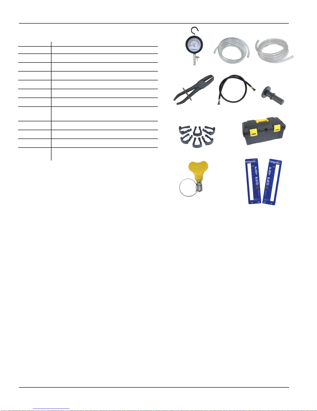
Kit Components and Accessories
Part Number Description
824266 High Pressure Gauge (0 to 8 bar scale)
824265 Low Pressure Gauge (-1 to 3 bar scale)
824149 Pressure Relief Hose (3mm ID x 1.8 m long)
824148 Bypass Hose (6.5 mm ID x 1.8 m long)
824144 Scissor Hose Clamps (Qty 2)
824147 Flowmeter Hose (9.5 mm ID x 1.2 m long)
824173 Hose Plug (Qty 2)
824143 Gasoline/Petrol Flowmeter Faceplates
(Liters/Minute) includes front and back plate
824183 Wing-Style Hose Clamp (Qty 4)
824172 Quick-connect Replacement Clips (Qty 6)
824267 Storage Case
MVA528 Diesel Flowmeter Faceplates (Liters/Minute)
includes front and back plate
824266/824265
824144
824172
824183
824149 824148
824147
824143/MVA528
824173
824267
Page Number - 4 Form 824262
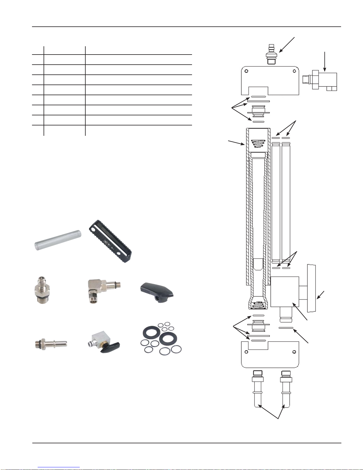
Flowmeter Parts
Part Number Description
1 824182 Flow Tube Shield
2 824177 Male Quick-Connect Fitting
3 824176 Bypass Port
4 824175 Flow Control Valve Knob
5 824174 Flowmeter Inlet/Outlet Connector (Qty 2)
6 824146 Flow Control Valve
7 824145 Flowmeter Seal Kit
824181 Flowmeter Boot
2
3
7
7
1
824182
824174
824181
824176824177
824146
824175
824145
10
4
7
6
7
Form 824262 Page Number - 5
5
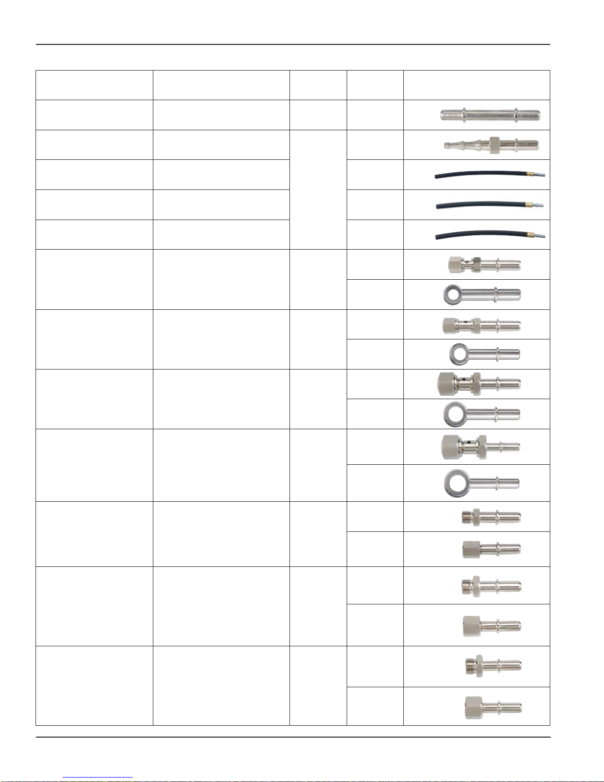
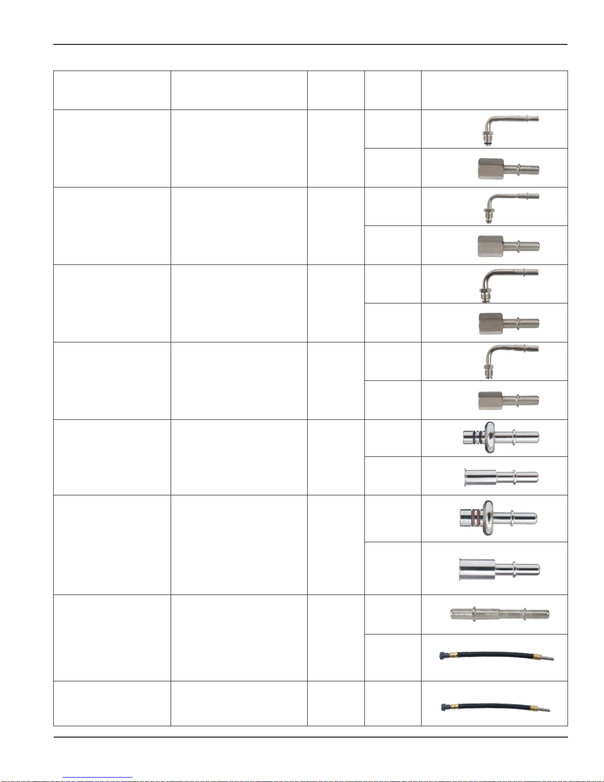
Fuel System Test Adapters
Description Applications Order No.
3
⁄8" Quick-change Adapter GM, Chrysler, Jeep/Eagle MVA512 1
1
⁄4" - 3⁄8" Barbed
Flex Hose Adapter
1
⁄4" Flex Hose Adapter
Vehicles with 1⁄4", 5⁄16"
or 3⁄8" rubber to steel
hose connection
Vehicles with 1⁄4" rubber
to steel hose connection
Reference
MVA505
5
⁄16" Flex Hose Adapter
3
⁄8" Flex Hose Adapter
M8 x 1.0
Banjo Adapter
M10 x 1.0
Banjo Adapter
Vehicles with 5⁄16" rubber
to steel hose connection
Vehicles with 3⁄8" rubber
to steel hose connection
Toyota MVA530
Toyota MVA531
No.
16
16A
16B
16C
13B
13C
14B
14C
M12 x 1.25
Banjo Adapter
M14 x 1.5
Banjo Adapter
M12 x 1.5
Ball Nose Adapter
M14 x 1.5
Ball Nose Adapter
M16 x 1.5
Ball Nose Adapter
Toyota, Lexus, Geo, Honda, Acura,
Hyundai, Mazda, Daihatsu, Chrysler
imports
European vehicles
with CIS fuel system
European vehicles
with CIS fuel system
European vehicles
with CIS fuel system
15B
MVA532
15C
23A
MVA533
23C
12A
MVA517
12B
10A
MVA518
10B
11A
MVA519
11B
Page Number - 6 Form 824262
Fuel System Test Adapters
Description Applications Order No.
M16 x 1.5 Adapter GM Vortec MVA520
M14 x 1.5 Adapter GM Vortec MVA521
3
⁄8" Flare Nut Adapter
5
⁄16" Flare Nut Adapter
Carbureted & early
fuel injected systems
Carbureted & early
fuel injected systems
MVA522
MVA523
Reference
No.
3A
3B
4A
4B
6A
6B
5A
5B
7A
3
⁄8" Spring Lock Adapter Ford fuel injection systems MVA524
7B
8A
1
⁄2" Spring Lock Adapter Ford fuel injection systems MVA525
8B
2B
5
⁄16" Quick-Change Adapter GM, Chrysler, Jeep/Eagle MVA526
2A
10mm Quick-Change Adapter Diesel MVA534 24
Form 824262 Page Number - 7
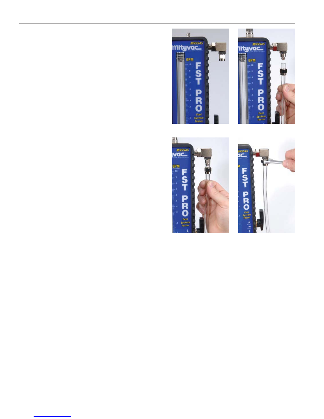
Fig. 1
Fig. 2
Fig. 3
Fig. 4
Page Number - 8 Form 824262
Setup and Installation
Determining Where to Install the FST
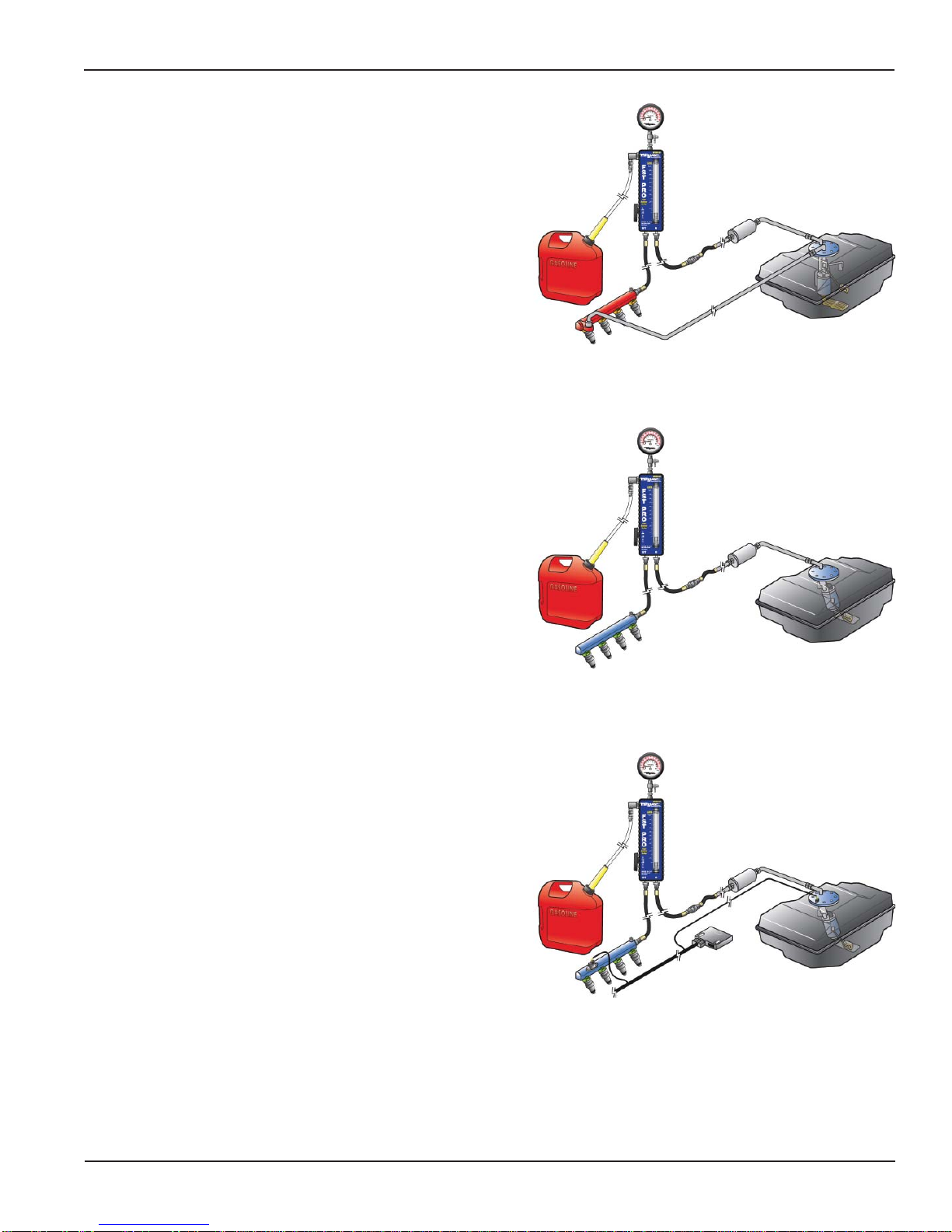
Inline Connection
Regardless of the type of fuel delivery system, the FST Pro is most effective at diagnosing malfunctions when connected inline with the flow
of fuel. The initial installation should be made at an access point along
the fuel supply line, as close as possible to the fuel rail (Figs. 5, 6 and
7). At this location, the fuel pressure and flow measured by the tester
will most accurately represent the conditions within the fuel rail. Due to
some engine compartment layouts and connector locations, it may be
necessary to connect the tester directly after the in-line fuel filter, which
may be located in the engine compartment, under the frame, or near
the fuel tank. In this case, be sure to carefully inspect the fuel supply
line between the tester and fuel rail for any irregularities such as leaks,
crimps, or kinks, as these may cause a false diagnosis based on the
tester readings.
Alternative Connection Locations
Connecting the FST inline as instructed above for the initial test,
ensures the most accurate fuel system diagnosis. However, in some
instances it may be beneficial to connect the tester at alternative locations to more accurately pinpoint the exact cause of a malfunction.
Performing additional diagnostics at different connection locations is
detailed in the Testing and Diagnostics section of this manual.
Fig. 5
Fig. 6
Fig. 7
Form 824262 Page Number - 9
Installation
Once the installation point has been determined, follow the instructions
below to setup the tester prior to disconnecting the fuel line.
1. Place the vehicle transmission in park or neutral, apply the parking
brake, and turn the key off.
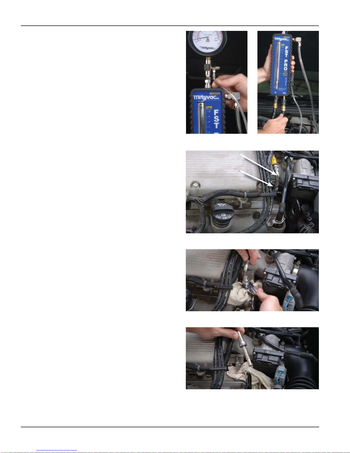
2. Hang the pressure gauge under the vehicle hood or other appropriate location.
3. Connect the flowmeter to the pressure gauge using the female
push-to-connect coupler extending from the bottom of the gauge,
and the male connector located on top of the flowmeter. Make sure
the quick-connect sleeve snaps forward to lock the connection.
NOTE: The flowmeter should hang vertically for the most accurate
fuel flow measurement.
4. Connect the 3 mm clear pressure relief hose to the barb extending
from the push-button pressure relief valve located just under the
gauge (Fig. 8).
5. Place the free ends of the bypass hose and pressure relief hose
into an approved gasoline fuel container. Secure hoses in fuel
container as necessary to prevent spills.
6. Connect one end of each 3/8" inlet and outlet connection hoses to
the bottom fittings on the FST flowmeter (Fig. 9).
7. Follow the vehicle manufacturer’s recommended procedure to
relieve the pressure from the vehicle fuel delivery system.
8. Locate the fuel supply line to the engine’s fuel rail, and select the
best location to disconnect the supply line and install the FST
(Fig. 10). If uncertain of the proper connection point, see the
previous section entitled Determining Where to Install the FST.
For additional assistance, consult the vehicle manufacturer’s
service information, or refer to the Types of Fuel Delivery Systems
section earlier in this manual.
If the engine has a cover, it will most likely have to be removed to
gain appropriate access.
9. Remove or disconnect any obstacles required to gain access to
the connection, and place shop towels under and around the connection to absorb fuel from the disconnected line.
T o minimize fuel spillage and reduce the amount of time the fuel
line is disconnected, try to identify the type of connection before
disconnecting the fuel line, and have the required FST connection
adapter(s) readily available (see Selecting and Installing Adapters
above). Also, identify the inlet and outlet hoses to the tester, and
keep them convenient.
10. Follow the vehicle manufacturer’s service information for the
proper method to disconnect the fuel line. Special wrenches or
disconnect tools may be required (Fig. 1 1).
WARNING: Avoid spilling fuel on hot engine parts. Clean-up any
fuel spills immediately after they occur.
1 1. Install the appropriate adapter into the fuel supply line extending
from the tank (Fig. 12).
Fig. 9Fig. 8
Fuel Line
Connection Location
Fig. 10
Fig. 11
Page Number - 10 Form 824262
Fig. 12
 Loading...