

Mityvac MV5532 User Manual
USER’S MANUAL
Have Technical Questions?
If you have questions, or require technical
service, please contact our trained service
technicians at:
1-314-679-4200 ext. 4782
Monday - Friday 7:30 am to 4:15 pm CST
Visit our website at www.mityvac.com for
new products, catalogs and instructions for
product use.
Need Service Parts?
To order replacement or service parts, visit
us online at www.mityvacparts.com or call
toll free 1-800-992-9898.
Digital Compression Tester
MODEL MV5532
SPECIFICATIONS
Max. Pressure : 300 PSI (20 Bar) (2,000 kPa)
www.mityvac.com
AUG - 2005 Section
Form 822856
- MV37
Page
- 1
2
10
9
12
8
11
4
1
5
3
6
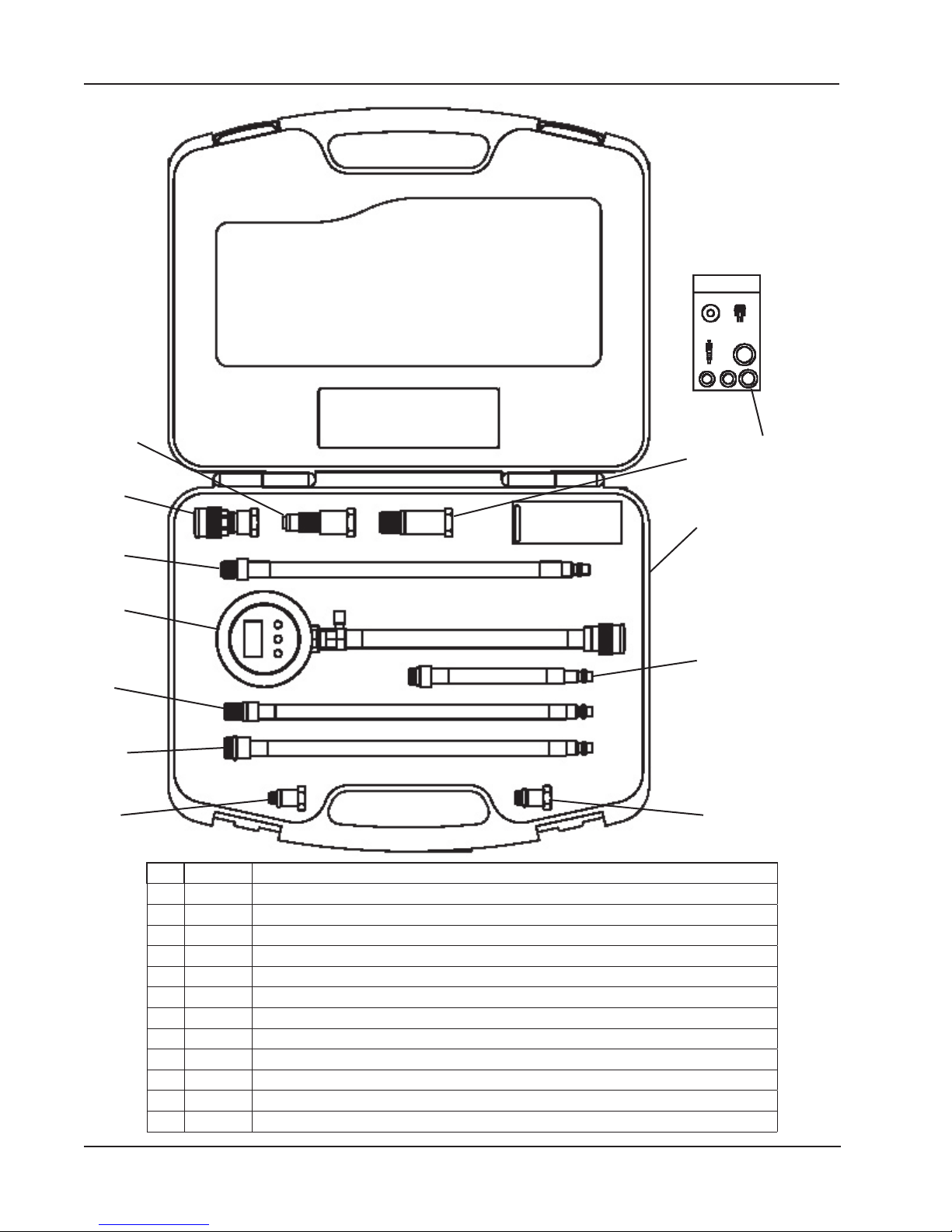
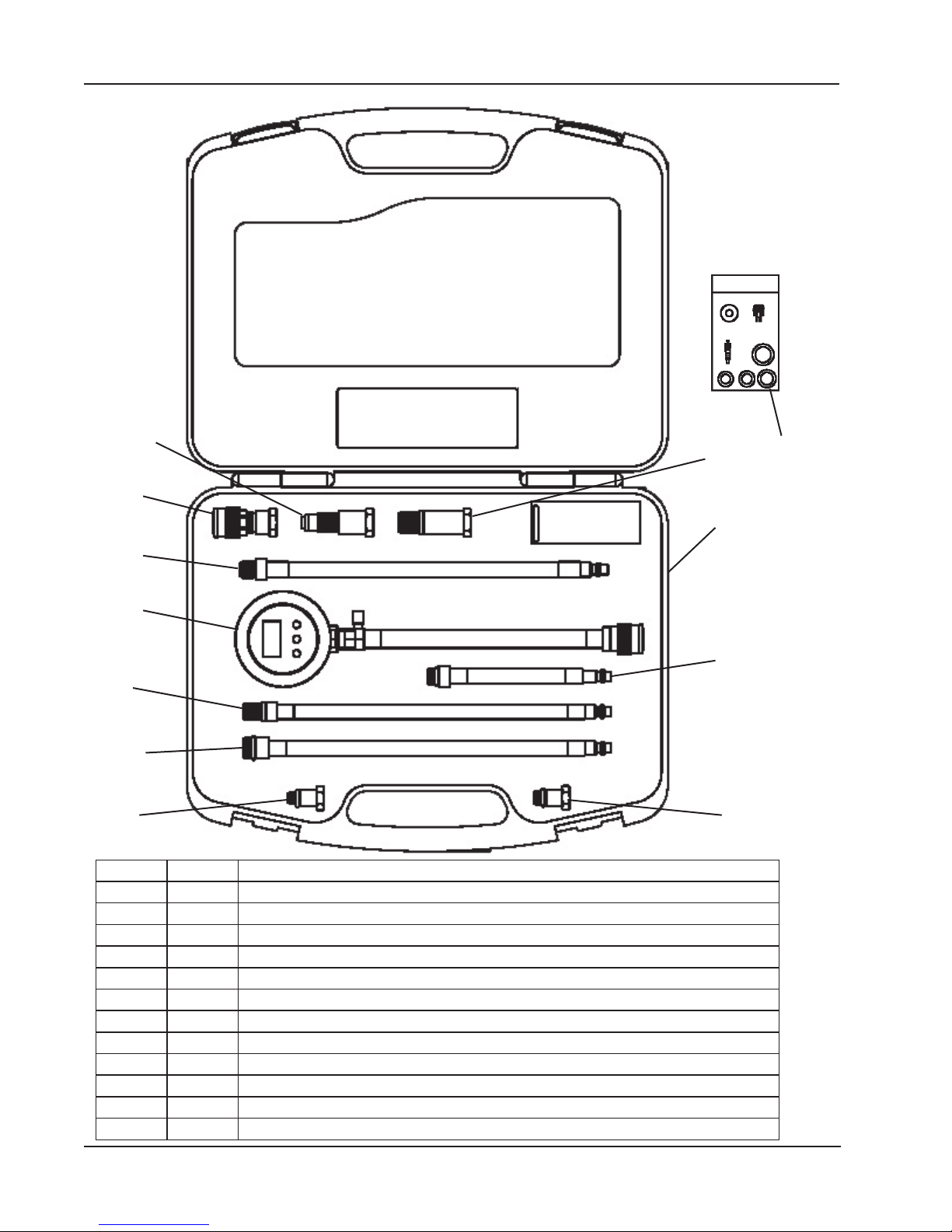
Item Part No. Description
1 823620 Compression Tester
2 MVA5506 14 mm long reach thread x 12” (305 mm) long
3 MVA5509 18 mm standard reach thread x 12” (305 mm) long
4 MVA5504 14 mm standard reach thread x 12” (305 mm) long
5 MVA5508 14 mm standard reach thread x 6” (150 mm) long
6 MVA5501 10 mm male thread x 14 mm standard reach female thread
7 MVA5502 12 mm male thread x 14 mm standard reach female thread
8 MVA5503 18 mm long reach male thread x 14 mm standard reach female thread
9 MVA5507 16 mm male thread for Ford Triton engines x 14 mm standard reach female thread
10 MVA5510 Air Hold Adapter
823621 Custom Molded Case
11
12 823441 Field Service Kit
Page Number - 2 Form 822856
7
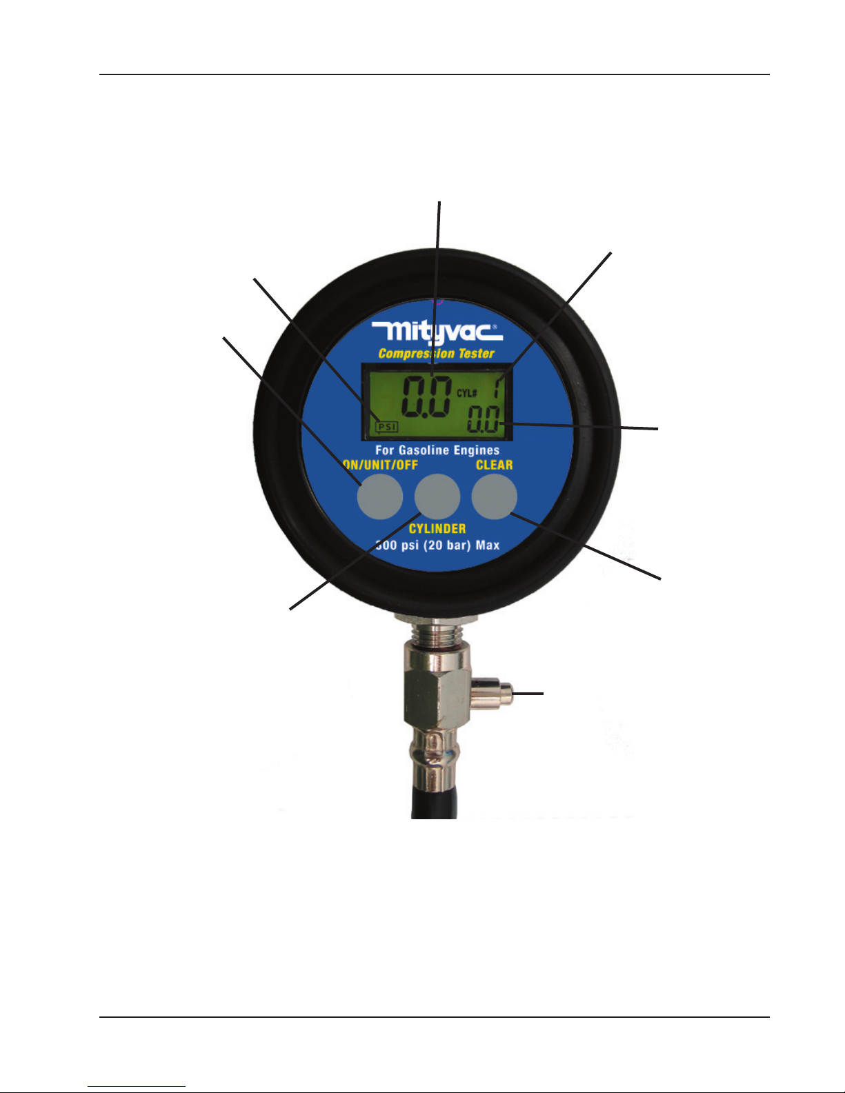
Current Unit Indication –
Displays current unit of
measure. Available units of
measure include PSI, Bar, or
kPa. Current unit of measure
is maintained when unit is
cycled off and on.
On/Unit/Off Button
– Pressing this button
when unit is off, turns
unit on. Pressing and
releasing this button
while the unit is on, advances the current unit
of measurement forward.
Pressing and holding
this button for 3 seconds
while unit is on, turns
unit off. Tester automatically shuts off after six
(6) minutes of non-use.
Compression values are
maintained when unit is
cycled off and on.
Cylinder Advance Button
– Pressing this button advanc-
es the cylinder number by one.
If the pressure in the hose assembly is not relieved by pressing the Pressure Relief Button
or disconnecting the hose at
the quick disconnect junction,
the values for current max and
stored max for the new cylinder
will reflect the stored hose pres
sure.
Current Pressure Indication –
Displays the maximum compression value for the indicated
cylinder until the Pressure Relief
Button is pressed. This is the
measurement of the residual
pressure maintained in the hose
assembly by the Schrader valve.
Pressure Relief Button
– Pressing this button relieves
the residual pressure in the tester hose assembly. The value
-
indicated for the Current Pressure will return to zero, but the
Maximum Compression value
will be maintained electronically
until the Clear Button is pressed.
Cylinder # Indication – Displays cylinder number related
to current and maximum compression values being displayed. Number is advanced
by pressing the Cylinder Button
Maximum Compression Indication
- Displays maximum
compression value for
the indicated cylinder. Holds the value
until the Clear Button
is pressed. Value is
stored electronically.
Clear Button
- Clears maximum
compression value
shown for indicated
cylinder. Clears
values for all cylinders and returns to
cylinder 1 if held for
3 seconds.
Page Number - 3Form 822856

Always read instructions carefully prior to use.
Safety Information
• Read and understand all safety precautions and operating instructions contained in this manual.
• Always wear eye protection when performing a compression test.
• Do not exceed the maximum rating of the tester; 300 psi
(20 bar) (2,000 kPa)
• Prior to testing, set the gearbox to neutral on all vehicles
or machinery having a standard transmission, or park for
automatic transmissions.
• Prior to engaging ignition, ensure that the fuel supply is
disabled using manufacturer’s recommended method.
• Make sure that all connections are secure prior to testing.
• Take precautions to avoid contact with hot engine surfaces.
Included in this Kit
• Digital Compression Tester comprising of test gauge with
rubber boot, 10” (250 mm) long, high pressure hose, and
female quick release coupler.
• (4) - Extended hose compression test adapters:
o 14 mm standard reach thread x 6.5” (165 mm) long
o 14 mm standard reach thread x 12” (305 mm) long
o 14 mm long reach thread x 12” (305 mm) long
o 18 mm standard reach thread x 12” (305 mm) long
• (4) - Plug style compression test adapters:
o 18 mm long reach male thread x 14 mm standard
reach female thread
o 16 mm male thread for Ford Triton engines x 14 mm
standard reach female thread
o 10 mm male thread x 14 mm standard reach female
thread
o 12 mm male thread x 14 mm standard reach female
thread
• Air Hold Adapter
• Custom blow-molded case
• Field service kit
the value of the previous test, or the CLEAR button was
pressed to erase the old value from memory.
Peak compression values can be stored for up to 12 cylinders. Each is displayed on the LCD along with the cylinder number. During and/or after completion of testing all
cylinders, the peak values can be reviewed by pressing the
CYLINDER button to scroll through the memory. Individual
peak values can be erased from memory by pressing the
CLEAR button when the appropriate cylinder and value are
displayed. Pressing the CLEAR button for 3 seconds at
any time will clear the memory for all cylinders and return
the display to cylinder 1.
How to Perform a Comression Test
Precautions & Diagnostic Notes:
WARNING: DO NOT use the ignition switch during the
compression test on fuel-injected vehicles. Use of a
remote starter switch to crank the engine is recommended. Fuel injectors on many late model vehicles
are triggered by the ignition switch during the cranking
mode, this could result in a fire hazard or contamination of the engine’s oil with fuel.
An engine in good operating condition will produce a
certain amount of pressure in each cylinder. Normally,
the cylinders should be within 10 percentage points of
one another and within the manufacturer’s specifications.
The pressure should rise smoothly on each stroke of the
engine, until it reaches a peak.
If the pressure reading fails to rise, or it remains the same
for several strokes of the engine and begins to rise, the
likely cause of the problem is a sticking valve.
If two adjacent cylinders show pressure readings of 20 or
more pounds below the other cylinder readings, suspect a
blown head gasket.
Functional Overview
The Mityvac Digital Compression Test Kit can perform wet
and/or dry compression tests to determine the pressure
produced in the cylinders of a gasoline engine. It can
measure, display, and store compression values of up to
300 psi (20 bar) (2,000 kPa) for up to 12 cylinders. It can
also be used as a tool for pressurizing an engine cylinder
to hold the valves closed while performing repairs.
When using this tester to perform a compression test on a
cylinder, the current peak compression value is displayed
in large numbers at the center of the LCD. This value
is automatically transferred to memory, and displayed in
smaller numbers at the bottom right of the display. When
the pressure relief button is depressed, the current compression reading returns to zero, but the peak value is
retained in memory and continues to be displayed in the
bottom right corner of the LCD. Repeated tests can be
run on the same cylinder, and the new current peak value
will be displayed by the large numbers. This new peak
value will not be retained in memory unless it surpasses
Page Number - 4 Form 822856
If a cylinder shows a pressure reading of 15 PSI (1 bar)
(100 kPa) or more pounds higher than the other cylinders,
the probable cause is carbon build-up inside the cylinder.
The Mityvac Digital Compression Test Kit can perform two
tests: the dry compression test and the wet compression
test. The result of performing these tests will provide an
indication of the condition of the piston rings, cylinders, and
valve-train.
Dry Compression Test Procedures:
1. Refer to the appropriate service manual for the compression specifications specific to the engine you are testing.
2. Start engine and allow engine to run until it reaches normal operating temperature (usually about 15 minutes.)
Turn engine OFF.
3. Install an auxiliary starter switch in the starting circuit.
4. While wearing eye protection, use compressed air to
carefully remove dirt and debris from the area around
the spark plugs.

5. Remove spark plugs one at a time, marking the number
of the cylinder they were removed from, and place them
on a clean flat surface. This will aid you in identifying
problem cylinders by allowing the comparison of spark
plug appearance to the compression level of a given
cylinder.
NOTE: When testing engines with two spark plugs
per cylinder, it is only necessary to remove the
spark plugs located on the exhaust side.
6. On vehicles with standard distributors, disconnect the
coil wire (high tension lead) from the distributor cap and
secure it to a suitable ground, or disable the ignition by
disconnecting the positive (BAT) terminal from the igni
tion coil.
7. On vehicles with a distributorless ignition (DIS), disable
the ignition system by removing the electronic ignition
(control) module fuse, or disconnect the crank angle
sensor.
NOTE: Refer to the appropriate service manual to
determine which fuse or component to temporarily
remove or disconnect.
8. Remove air cleaner from carburetor or throttle body and
secure throttle linkage in wide-open throttle (WOT) position.
NOTE: NEVER place anything inside the throttle
body; internal damage to the engine could result.
On vehicles equipped with port fuel injection,
remove throttle linkage covers (as necessary) and
secure throttle linkage in the wide-open throttle
(WOT) position.
9. Crank engine several times to ensure removal of any for
eign matter that may have fallen into the cylinders during
preparation for test.
10. Select the appropriate test adapter and thread it into the
spark plug hole of cylinder 1 until the o-ring on the adapter seats firmly (do not tighten with a wrench).
11. If required, thread a test adapter with a hose onto the in
stalled adapter until the o-ring seats firmly (do not tighten
with a wrench).
12. Connect the test gauge to the opposite end of the test
adapter hose.
13. Turn the tester on by pressing the ON/UNIT/OFF button.
14. Press and hold the CYLINDER button for at least three
(3) seconds to clear the memory and return the cylinder
indicator to “CYL# 1”.
15. While watching the test gauge, crank the engine as least
five (5) compression strokes or until the pressure reading
stops increasing (the peak compression value will auto
matically be stored in memory).
16. Relieve the pressure in the tester by pressing the pres
sure relief button.
17. Disconnect the gauge and remove the test adapter(s)
from cylinder 1.
18. Install the test adapter(s) into cylinder 2 and reconnect
the gauge.
19. Advance the cylinder number shown on the tester LCD to
2 by pressing the CYLINDER button.
20. Repeat the compression test on cylinder 2 and all remaining cylinders. Be sure to advance the cylinder number on
the tester for each cylinder.
-
21. After testing all cylinders, review the values of each cyl
inder by pressing the CYLINDER button to scroll through
the results.
22. If any of the cylinder readings are found to be low or
uneven, perform wet compression test.
23. When compression test is complete, return the spark
plugs to their respective cylinders and the throttle and
ignition components to their normal positions.
Wet Compression Test Procedure
The wet compression test is a way to remove the influence
of worn piston rings, pistons and cylinders from the compression test. After completing the dry compression test,
squirt approximately one teaspoon of engine oil into the
spark plug holes and crank the engine several times to seal
the piston rings. Repeat the dry compression test outlined
above. NOTE: If the readings during the wet compression
test are greater, then air is leaking around worn or damaged piston rings. If the reading is approximately the same
for both wet and dry tests then the valves, valve lifters or
the camshaft lobes are worn. Any low reading of cylinder
compression indicates worn or damaged parts.
Small Engine Compression Testing
The Mityvac Digital Compression Test Kit has two (2)
adapters, 10mm and 12mm, that allow it to be used on
small engines such as those found on lawn mowers, chain
saws and line trimmers. To use these adapters:
-
1. Disconnect the spark plug wire and remove the spark
plug.
2. Thread the appropriate size adapter onto the compres
sion tester main hose end until the o-ring seats (do not
use a wrench to tighten).
-
3. Thread the assembly into the cylinder spark plug hole
until the o-ring on the adapter seats firmly (do not use a
wrench to tighten).
4. Ensure the spark plug is grounded to the cylinder head
or is insulated in a way that will prevent an electric
shock hazard.
5. Crank the engine over using the pull cord (or starter if
electric) a minimum of 5 revolutions. This will allow the
cylinder to build sufficient compression to be measured.
6. Refer to the manufacturer’s data to determine the cor
rect reading
-
Using the Pressure Hold Adapter
The Mityvac Professional Compression Tester comes with
a pressure hold adapter. This adapter is used to perform
valve seal replacement on an engine without removing the
cylinder head(s). To use the adapter:
1. Remove the spark plug from the desired cylinder.
2. Select the appropriate extension hose that will fit the
spark plug hole.
3. Using the valve core tool (from the field service kit in-
cluded), remove the valve core from the end of the hose
and lay it aside.
-
-
-
Page Number - 5Form 822856

4. Thread the extension hose into the spark plug hole
until the o-ring seats; do not use pliers or a wrench to
tighten.
5. Attach the Air Hold Adapter to the extension hose.
6. Attach a shop air hose to the Air Hold Adapter, this will
maintain air pressure in the cylinder to hold the valves
closed while performing repairs. (It may be necessary
to rotate the engine until all valve are closed and air is
holding in the cylinder)
Note: Air Hold quick connector does not come with a
compressed air line fitting to adapt to your air source.
This will have to be purchased separately to fit your
system.
Contacting Lincoln Industrial Corp.
Lincoln Industrial Corporation,
One Lincoln Way,
St. Louis, MO 63120
Phone: (314) 679-4200 Ext. 4410
Fax: (800) 424-5359
E-mail: custserv@lincolnindustrial.com
For technical questions, please contact our Technical Service Department:
Phone:(314) 679-4200 Ext 4782
Fax: (314) 679-HELP (4357)
E-mail: techserv@lincolnindustrial.com
Visit our Web Site at: www.mityvac.com
TO AVOID PERSONAL INJURY AND/OR VEHICLE
DAMAGE:
While some precautions are specified in this manual,
and should be noted to avoid personal injury or vehicle
damage, it is not possible for these cautions to cover all
conceivable ways in which service or testing might be
done, or all possible hazardous consequences of each
way, nor could Lincoln possibly know or investigate all
such ways. It is therefore the responsibility of anyone
using this manual or any other Mityvac product, to satisfy
him or herself completely that neither personal safety nor
vehicle safety will be jeopardized by the service methods
selected. Any such injury or damage is entirely the user’s
responsibility. This device is not to be used in any man
-
ner on the human body.
Lincoln Industrial Standard Warranty
LIMITED WARRANTY
Lincoln warrants the equipment manufactured and supplied by Lincoln to be free from defects in material and workmanship for a period
of one (1) year following the date of purchase, excluding therefrom any special, extended, or limited warranty published by Lincoln. If
equipment is determined to be defective during this warranty period, it will be repaired or replaced, within Lincoln’s sole discretion, with
out charge.
This warranty is conditioned upon the determination of a Lincoln authorized representative that the equipment is defective. To obtain
repair or replacement, you must ship the equipment, transportation charges prepaid, with proof of purchase to a Lincoln Authorized War
ranty and Service Center within the warranty period.
This warranty is extended to the original retail purchaser only. This warranty does not apply to equipment damaged from accident,
overload, abuse, misuse, negligence, faulty installation or abrasive or corrosive material, equipment that has been altered, or equipment
repaired by anyone not authorized by Lincoln. This warranty applies only to equipment installed, operated and maintained in strict ac
cordance with the written specifications and recommendations provided by Lincoln or its authorized field personnel.
THIS WARRANTY IS EXCLUSIVE AND IS IN LIEU OF ANY OTHER WARRANTIES, EXPRESS OR IMPLIED, INCLUDING, BUT NOT
LIMITED TO, THE WARRANTY OF MERCHANTIBILITY OR WARRANTY OF FITNESS FOR A PARTICULAR PURPOSE.
In no event shall Lincoln be liable for incidental or consequential damages. Lincoln’s liability for any claim for loss or damages arising
out of the sale, resale or use of any Lincoln equipment shall in no event exceed the purchase price. Some jurisdictions do not allow the
exclusion or limitation of incidental or consequential damages, therefore the above limitation or exclusion may not apply to you.
This warranty gives you specific legal rights. You may also have other rights that vary by jurisdiction.
Customers not located in the Western Hemisphere or East Asia: Please contact Lincoln GmbH & Co. KG, Walldorf, Germany, for your
warranty rights.
Lincoln Industrial Contact Information
-
-
-
To find Lincoln Industrial’s Nearest Service Center
Call one of the following numbers, you may also use our Website
Page Number - 6 Form 822856
Customer Service 314-679-4200
Website: lincolnindustrial.com
MANUEL D’UTILISATION
Questions techniques ?
Si vous avez des questions ou avez besoin
d’assistance technique, contacter nos techniciens qualifiés à :
1-314-679-4200, poste 4782
Lundi à mardi, 7h30 à 16h15 heure du centre des Etats-Unis.
Rendez visite à notre site web à www.
mityvac.com pour découvrir nos nouveaux
produits, obtenir des catalogues ou des
instructions d’utilisations pour nos produits.
Besoin de pièces ?
Pour commander des pièces de rechange
ou des pièces consommables, rendez-nous
visite en ligne à www.mityvacparts.com ou
appelez gratuitement +1-800-992-9898.
Compressiomètre numérique
MODELE MV5532
DONNEES TECHNIQUES
Pression maximale : 20 bar
(2 000 kPa ; 300 psi)
www.mityvac.com
Page Number - 7Form 822856
2
10
9
12
8
11
4
1
5
3
6
Référence N° de cat. Description
1 823620 Compressiomètre
2 MVA5506 Filet long de 14 mm x 305 mm (12 in) de long
3 MVA5509 Filet standard de 18 mm x 305 mm (12 in) de long
4 MVA5504 Filet standard de 14 mm x 305 mm (12 in) de long
5 MVA5508 Filet standard de 14 mm x 150 mm (6 in) de long
6 MVA5501 Filet mâle de 10 mm x filet femelle standard de 14 mm
7 MVA5502 Filet mâle de 12 mm x filet femelle standard de 14 mm
8 MVA5503 Filet mâle long de 18 mm x filet femelle standard de 14 mm
9 MVA5507 1Filet mâle de 6 mm pour les moteurs Triton de Ford x filet femelle standard de 14 mm
10 MVA5510 Adaptateur de maintien d’air
11
12 823441 Kit de réparation sur place
823621 Mallette moulée sur mesure
Page Number - 8 Form 822856
7
 Loading...