

Mityvac 04700 User Manual [en, de, es, fr]
USER’S MANUAL
Have Technical Questions?
If you have questions, or require technical
service, please contact our trained service
technicians at:
1-314-679-4200 ext. 4782
Monday - Friday 7:30 am to 4:15 pm CST
Visit our website at www.mityvac.com for
new products, catalogs and instructions for
product use.
Need Service Parts?
To order replacement or service parts, visit
us online at www.mityvacparts.com or call
toll free 1-800-992-9898.
SPECIFICATIONS:
Air Inlet Size: 1/4” NPT
Min. Inlet Air Pressure
Max. Inlet Air Pressure: 120 PSI (8.3 Bar)
: 90 PSI (6.2 Bar)
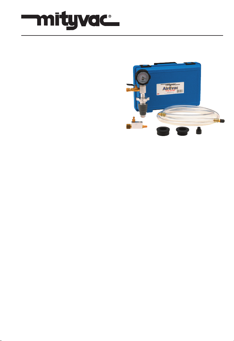
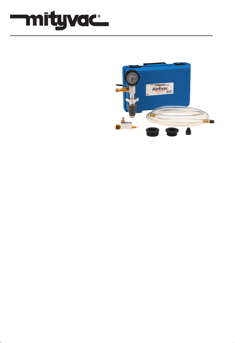
AirEvac
MODEL 04700
OCT - 2004
Form 823538
Section
- MV28
Page
- 1
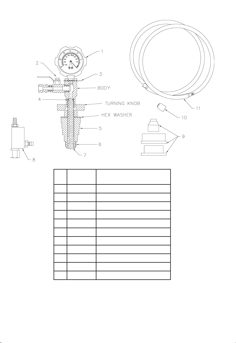
PART
NO.
1 823321 VACUUM GAUGE
2 823484 FLOW CONTROL VALVE
3 823483 RETAINING CLIP
4 823482 O-RING
5 823479 RUBBER ADAPTER KIT
6 823480 METAL RING
7 823481 BRASS BOLT
8 823491 VACUUM PUMP ASSEMBLY
9 823486 RUBBER BUSHING KIT
10 823487 SCREEN CAP
11
823485 HOSE ASSEMBLY
DESCRIPTION
Page Number - 2
Form 823538

CAUTION!
TO AVOID PERSONAL INJURY AND/OR
VEHICLE DAMAGE:
While some precautions are specified in
this manual, and should be noted to avoid
personal injury or vehicle damage, it is
not possible for these cautions to cover all
conceivable ways in which service or testing might be done, or all possible hazardous consequences of each way, nor could
Lincoln possibly know or investigate all
such ways. It is therefore the responsibility
of anyone using this manual or any other
Mityvac product, to satisfy him or herself
completely that neither personal safety nor
vehicle safety will be jeopardized by the service methods selected. Any such injury or
damage is entirely the user’s responsibility.
This device is not to be used in any manner
on the human body.
Instructions for Evacuating the
Cooling System and Checking
for Leaks
Important: This kit is designed for
servicing a variety of vehicles in a
safe, convenient manner. However,
differences in radiator and expansion tank filler necks prevent its use
on every possible make and model.
The procedures below are to serve as
guidelines for the use of this equipment, in addition to these guidelines,
always follow the manufacturer’s recommended procedures when servicing each unique vehicle.
Never remove the radiator cap or
expansion tank cap while the engine
is at operating temperature. Always
allow the engine to cool before removing the radiator cap or expansion tank
cap. The cooling system is under
pressure. Failure to allow the engine
to cool before opening the cooling
system could result in serious injury.
Form 823538
1. Properly position the vehicle for
service access to the radiator or
coolant expansion tank. Turn on the
heater control, and set it to its highest
temperature setting.
2. Thread a ¼” NPT air coupler nipple
(not included) compatible with your
compressed air system, into the
Vacuum Pump Assembly.
Figure 1
3. After ensuring the engine and cooling
system are cool, cautiously remove
the cap from the radiator or coolant
expansion tank.
4. Turn the tension knob on the Cooling
System Adapter Assembly counterclockwise until all tension has been
relieved from the expandable rubber
body. (See Figure 2.)
5. Insert the expandable rubber body of
the Cooling System Adapter Assem
bly into the filler neck of the radiator
or coolant expansion tank until the
largest possible diameter fits snuggly.
Note: In case none of the diameters
on the expandable rubber body fits
snuggly, two additional bushings
have been provided. These bushings
install over the second step of the
rubber body, and allow a snug fit with
larger diameters fill necks. A third
“micro-neck” rubber adapter has also
been included, and can be installed
onto the head of the shaft on the
adapter, below the expandable rubber
body. (See Figure 2).
Page Number - 3
-
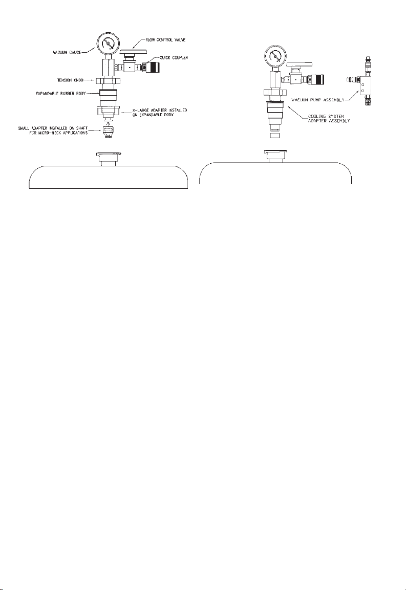
Figure 2
Figure 3
6. Turn the tension knob clockwise to
expand the rubber body until it comes
into firm contact with the interior wall
of the radiator or expansion tank filler
neck.
7. Check the connection by holding the
radiator or expansion tank stable
while carefully attempting to pull up
on the adapter. If the adapter comes
free or is not snug, increase the tension by further rotating the tension
knob.
Caution: Some late-model vehicles
are equipped with radiators or
coolant expansion tanks made of
plastic. Excessive over-tightening
(expansion) of the rubber adapter
could result in cracking the radiator or expansion tank. Use caution
when tightening the expandable
rubber adapter.
8. Utilizing the quick coupler connection,
connect the Vacuum Pump Assembly
to the Cooling System Adapter As
sembly. (See Figure 3.)
9. Connect clean, dry, regulated compressed air between 90 and 120 psi
(6.2 to 8.3 bar), to the Vacuum Pump
Assembly by means of the previously
installed air coupler nipple.
-
10. Turn on the compressed air, and
open the flow control valve on the
Cooling System Adapter Assembly.
The venturi action of the vacuum
pump will make a hissing noise as air
is removed from the cooling system.
If the cooling system is not empty,
coolant may be sucked through the
vacuum pump and sputter from the
muffler.
11. While watching the gauge, allow the
vacuum pump to pull air from the
cooling system until it reaches 24 to
26 in. Hg (81 to 88 kPa). This process should take less than a minute.
Note: As air is evacuated from the
cooling system, it is normal for radiator hoses to collapse. If the system
fails to pull a vacuum, check to see
if there are any overflow hoses that
need to be clamped off in order to
produce a closed system.
12. Once the cooling system has reached
24 to 26 in. Hg (81 to 88 kPa) vacuum, close the valve on the Cooling
System Adapter Assembly, disconnect the air supply, and then discon
nect the Vacuum Pump Assembly.
-
Page Number - 4
Form 823538
13. Watch the gauge for at least 30
seconds. It will maintain the 24 to 26
in. Hg (81 to 88 kPa) reading if the
system does not leak.
14. Follow the procedures below to prop
erly refill the cooling system before
relieving the vacuum from the system.
5. When the vacuum gauge reading
reaches zero (0), the cooling system
is full.
6. Remove the Cooling System Adapter
-
from the radiator or expansion tank
by turning the tension knob counterclockwise.
Refilling the cooling system
1. Follow the procedure above to evacu
ate and check the cooling system for
leaks. If the system has a leak, repair
it and re-evacuate the system.
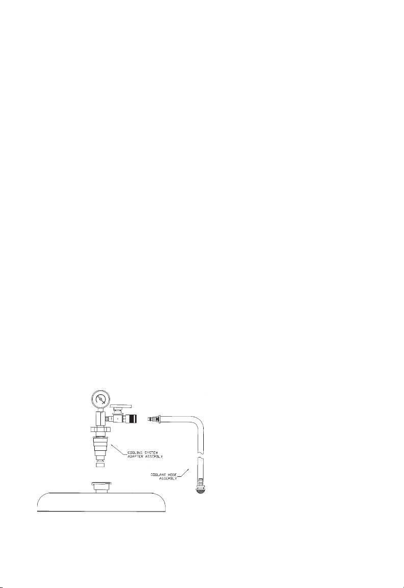
2. With a vacuum of 24 to 26 in. Hg (81
to 88 kPa) on the system, connect the
Coolant Hose Assembly to the Coolant System Adapter Assembly. (See
Figure 4.)
3. Submerse the free end of the coolant
hose into a supply of coolant. Ensure
there is enough coolant to refill the
system, or air will be pulled back into
the system, and the system will not fill
to the proper level.
4. Open the flow control valve on the
Coolant System Adapter Assembly,
and the system will refill with coolant.
Figure 4
7. Start the engine and allow it to reach
operating temperature.
-
8. Top-off the coolant level in the radia
tor or expansion tank as required, and
reinstall the cap.
-
Form 823538
Page Number - 5
MODE D’EMPLOI
Vous Avez des Questions Techniques ?
Si vous avez des questions ou vous
avez besoin de support technique,
merci de bien vouloir appeler nos
techniciens au :
1-314-679-4200 poste 4782
Du lundi au vendredi de 7:30 à 16:15
CST
Allez sur notre site Internet www.
mityvac.com pour voir les nouveaux
produits, les catalogues et les modes
d’emploi.
AirEvac
MODÈLE 04700
Vous Avez Besoin de Pièces Déta
chées ?
Pour commander des pièces de
rechange ou des pièces détachées,
allez sur notre site Internet www.
mityvacparts.com ou appelez notre
numéro vert au 1-800-992-9898.
Caractéristiques Techniques:
Taille de l’admission d’air : 1/4” NPT
Pression minimale de l’admission
d’air : 6,2 bars (90 PSI)
Pression maximale de l’admission
d’air : 8,3 bars (120 PSI)
OCT - 2004 Formulaire 823538 Section – MV28 Page – 1
Page Number - 6
-
Form 823538
 Loading...