

MityCAM MityCAM-B2521, MityCAM-B1910 User Manual
MityCAM-B2521 and
MityCAM-B1910 User Manual
60-000007
May 12, 2015
www.criticallink.com

MityCAM-B1910/B2521 User’s Manual
Contents
1 Introduction .................................................................................................................................................... 5
1.1 Additional Documentation ....................................................................................................................................... 5
1.2 Vocabulary ................................................................................................................................................................ 5
1.3 Important Differences .............................................................................................................................................. 5
1.3.1 Sensor Size ............................................................................................................................................................. 5
1.3.2 Sensor Readout Order ........................................................................................................................................... 6
1.3.2.1 MityCAM-B1910 ................................................................................................................................................. 6
1.3.2.2 MityCAM-B2521 ................................................................................................................................................. 6
2 Continuous High Speed Operation via Camera Link ........................................................................................... 7
2.1 Expanded 8-bit Mode (8 bit x 10 pixels) ................................................................................................................... 7
2.2 Expanded 16-bit Mode (16 bit x 5 pixels) ................................................................................................................. 7
2.3 Base 8-bit Mode (8 bit x 2 pixels) ............................................................................................................................. 7
2.4 Base 16-bit Mode (16 bit x 1 pixel) ........................................................................................................................... 8
2.5 Base 12-bit Mode (12 bit x 2 pixels) ......................................................................................................................... 8
3 Region of Interest ............................................................................................................................................ 8
3.1 Restrictions ............................................................................................................................................................... 8
3.1.1 MityCAM-B2521..................................................................................................................................................... 8
3.1.2 MityCAM-B1910..................................................................................................................................................... 8
3.2 MityViewer Restrictions............................................................................................................................................ 9
3.3 Important Note ......................................................................................................................................................... 9
4 Exposure & Frame Interval Time ...................................................................................................................... 9
4.1 Frame Interval ........................................................................................................................................................... 9
4.2 Exposure ................................................................................................................................................................. 10
4.3 Configuring .............................................................................................................................................................. 10
4.3.1 Camera Link ......................................................................................................................................................... 10
4.3.2 MityViewer .......................................................................................................................................................... 11
5 SCLK .............................................................................................................................................................. 12
6 GPIOs ............................................................................................................................................................ 12
6.1 Input ........................................................................................................................................................................ 12
6.1.1 Camera Link ......................................................................................................................................................... 12
6.1.2 MityViewer .......................................................................................................................................................... 13
6.2 Output ..................................................................................................................................................................... 13
6.2.1 Camera Link ......................................................................................................................................................... 14
6.2.2 MityViewer .......................................................................................................................................................... 14
7 External Trigger ............................................................................................................................................. 14
7.1 Timing Characteristics ............................................................................................................................................. 14
7.1.1 Rolling Shutter ..................................................................................................................................................... 14
7.1.2 Global Shutter ...................................................................................................................................................... 14
7.2 Configuration .......................................................................................................................................................... 16
7.2.1 Camera Link ......................................................................................................................................................... 16
7.2.2 MityViewer .......................................................................................................................................................... 17
8 Shutter Strobe ............................................................................................................................................... 19
8.1 Rolling Shutter ........................................................................................................................................................ 19
8.1.1 Internal Trigger .................................................................................................................................................... 19
8.1.2 External Trigger .................................................................................................................................................... 19
Page 2 of 27 60-000007
May 12, 2015
www.criticallink.com

MityCAM-B1910/B2521 User’s Manual
8.2 Global Shutter ......................................................................................................................................................... 20
8.3 Configuring .............................................................................................................................................................. 20
8.3.1 Mity Viewer.......................................................................................................................................................... 20
8.3.2 Camera Link ......................................................................................................................................................... 21
9 Camera Link .................................................................................................................................................. 22
9.1 Camera Link Configuration ..................................................................................................................................... 23
9.1.1 Camera Link Output Mode .................................................................................................................................. 23
10 MityCAM-B2521 Specific Configurations....................................................................................................... 23
10.1 Pseudo-One Port Mode ........................................................................................................................................ 23
10.1.1 Limitations ......................................................................................................................................................... 24
10.1.2 Configuration ..................................................................................................................................................... 24
11 MityCAM-B1910 Specific Configurations....................................................................................................... 24
12 Network Configuration ................................................................................................................................ 24
13 Firmware Upgrade ....................................................................................................................................... 25
14 Connecting via RNDIS to a Windows PC ........................................................................................................ 26
15 Revision History........................................................................................................................................... 27
Figures
Figure 1 MityCAM-B2521 Readout Order ..................................................................................................................... 6
Figure 2 Potential Leakage / Blooming with Reduced Vertical ROIs ............................................................................ 9
Figure 3 CIS Snapshot Control Window ...................................................................................................................... 11
Figure 4 Update GPIO Pin States ................................................................................................................................ 13
Figure 5 Global Shutter Exposure (Exposure less than ROI Height+16 row times) .................................................... 15
Figure 6 Global Shutter Exposure (Exposure greater than ROI Height+16 row times) .............................................. 15
Figure 7 Global Shutter Exposure is sampled on a row time (1 row of jitter possible) .............................................. 15
Figure 8 MityViewer CIS Calibration Window Configured for External Trigger .......................................................... 17
Figure 9 MityViewer Log Window for Trigger Configuration...................................................................................... 17
Figure 10 MityViewer Snapshot Control Window, Configure for Continuous Capture.............................................. 18
Figure 11 Shutter Strobe Timing in Rolling Shutter Mode .......................................................................................... 19
Figure 12 Strobe to Exposure Delay (1 row time) ....................................................................................................... 19
Figure 13 “Shutter” Strobe Selection in MityViewer GPIO Configuration .................................................................. 21
Figure 14 Network Configuration Webpage ............................................................................................................... 25
Figure 15 Typical Windows USB RNDIS Adapter Properties ...................................................................................... 26
Figure 16 Internet Protocol Version 4 Properties Box ................................................................................................ 26
Figure 17 Static IP configuration Settings .................................................................................................................. 27
Table 1 Reference Documentation ............................................................................................................................... 5
Table 2 Steps to Enter 8x10 Expanded Camera Link .................................................................................................... 7
Table 3 Steps to Enter 16x5 Expanded Camera Link .................................................................................................... 7
Table 4 Steps to Enter 8x2 Base Camera Link ............................................................................................................... 7
Table 5 Steps to Enter 16x1 Base Camera Link ............................................................................................................. 8
Table 6 Steps to Enter 12x2 Expanded Camera Link .................................................................................................... 8
Page 3 of 27 60-000007
May 12, 2015
www.criticallink.com
Tables

MityCAM-B1910/B2521 User’s Manual
Table 7 Range of Frame Interval Times ........................................................................................................................ 9
Table 8 Allowed Exposure Times ................................................................................................................................ 10
Table 9 Row Times per SCLK frequencies for 1910 and 2521 Cameras ...................................................................... 12
Table 10 GPIO Modes ................................................................................................................................................. 12
Table 11 Camera Link GPIO output configuration commands ................................................................................... 14
Table 12 Global Shutter Timing Parameters ............................................................................................................... 15
Table 13 Camera Link Commands for Configuring GPIO to Generate Shutter Strobe ............................................... 21
Table 14 Maximum Supported SCLK Rates for Different Camera Link Output Modes .............................................. 22
Table 15 Maximum Supported Frame Rates for Different Camera Link Modes ........................................................ 22
Table 16 Minimum Exposure Time as a Function of Output Camera Link Mode ....................................................... 22
Table 17 Required Camera Link Commands to Enter a Given Camera Link Output Mode ........................................ 23
Table 18: Pseudo-One Port Mode Commands ........................................................................................................... 24
Table 19: Row-Interleaved Mode Commands ............................................................................................................ 24
Table 20 Factory Default Network Address Settings .................................................................................................. 24
Page 4 of 27 60-000007
May 12, 2015
www.criticallink.com
MityCAM-B1910/B2521 User’s Manual
Document #
Title
Description
60-000004
MityCAM-B1910 Camera Link
Interface Document
Provides complete application programmer interface
information for serial command port of Camera Link
interface for MityCAM-B1910.
60-000005
MityCAM-B2521 Camera Link
Interface Document
Provides complete application programmer interface
information for serial command port of Camera Link
interface for MityCAM-B2521.
60-000008
MityCAM Camlink Panel User
Guide
MityCAM Cam Link Panel User Guide
P-10281
MityCAM Firmware Upgrade
Procedure
Provides description of steps needed to upgrade
MityCAM firmware.
1 Introduction
The purpose of this document is to outline the specific features of the MityCAM-B1910 and MityCAM-B2521
cameras.
1.1 Additional Documentation
In addition to this document, the following documents are also useful / pertinent to the use and operation of the
MityCAM-B1910 and MityCAM-B2521 cameras.
Table 1 Reference Documentation
1.2 Vocabulary
Sensor – The sCMOS sensor on the headboard of the camera hardware stack.
Row – One complete row of pixels output from the sensor.
SCLK – The clock provided by the SoC Processor board to the sensor for it to operate. There are a fixed number of
SCLK values supported by the camera.
Row time – A fixed number of SCLK periods which includes time to shift and convert charge as well as read out the
data from the sensor. Integral multiples of “row time” is the basic unit of time recognized by the sensor.
1.3 Important Differences
1.3.1 Sensor Size
The primary difference between the two sensors is their maximum resolution.
Maximum 2521 ROI Height = 2160 rows
Maximum 1910 ROI Height = 1080 rows
The 2521 sensor has two halves, a top and bottom half each with 1080 rows which operate in parallel, making the
timing very similar for both sensors. Because of this difference for MityCAM-B2521, ROI
should be divided by
Height
2 from the output image’s height when considering timing in the tables in the following sections.
Page 5 of 27 60-000007
May 12, 2015
www.criticallink.com
MityCAM-B1910/B2521 User’s Manual
1.3.2 Sensor Readout Order
1.3.2.1 MityCAM-B1910
This is a raster order camera. Rows are output from the top of the sensor down (or from the bottom up). Most
frame grabbers should be able to handle this method of data output.
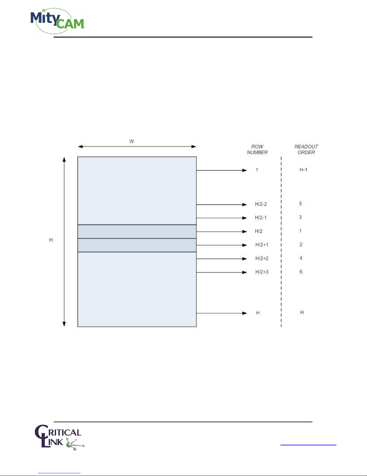
1.3.2.2 MityCAM-B2521
Normal operation for the camera is to read from the center out. The result is data being output row by row,
interleaved, from the center of the sensor out. For maximum frame-rate, the frame grabber must perform the
unwinding of the interleaved rows.
The camera can also be configured to output in raster order. For information on this mode and the limitations on
the camera, see section 10.1 “Pseudo-One Port Mode.”
Page 6 of 27 60-000007
May 12, 2015
www.criticallink.com
Figure 1 MityCAM-B2521 Readout Order
MityCAM-B1910/B2521 User’s Manual
Step
Command
Comment
1
<SOMD 0>
Go to expanded Camera Link output
2
<SBPP 0>
Go to 8 bpp output
3
<SCLK n>
See Table 14 in Section 9 for maximum SCLK.
4
<SFIT 0>
Set the frame-rate to the maximum supported
5
<STRT>
Begin continuously capturing
Step
Command
Comment
1
<SOMD 0>
Go to expanded Camera Link output
2
<SBPP 1>
Go to 16 bpp output
3
<SCLK n>
See Table 14 in Section 9 for maximum SCLK.
4
<SFIT 0>
Set the frame-rate to the maximum supported
5
<STRT>
Begin continuously capturing
Step
Command
Comment
1
<SOMD 1>
Go to Base Camera Link output
2
<SBPP 0>
Go to 8 bpp output
3
<SCLK n>
See Table 14 in Section 9 for maximum SCLK.
4
<SFIT 50000>
Set the frame-rate to the maximum supported
5
<STRT>
Begin continuously capturing
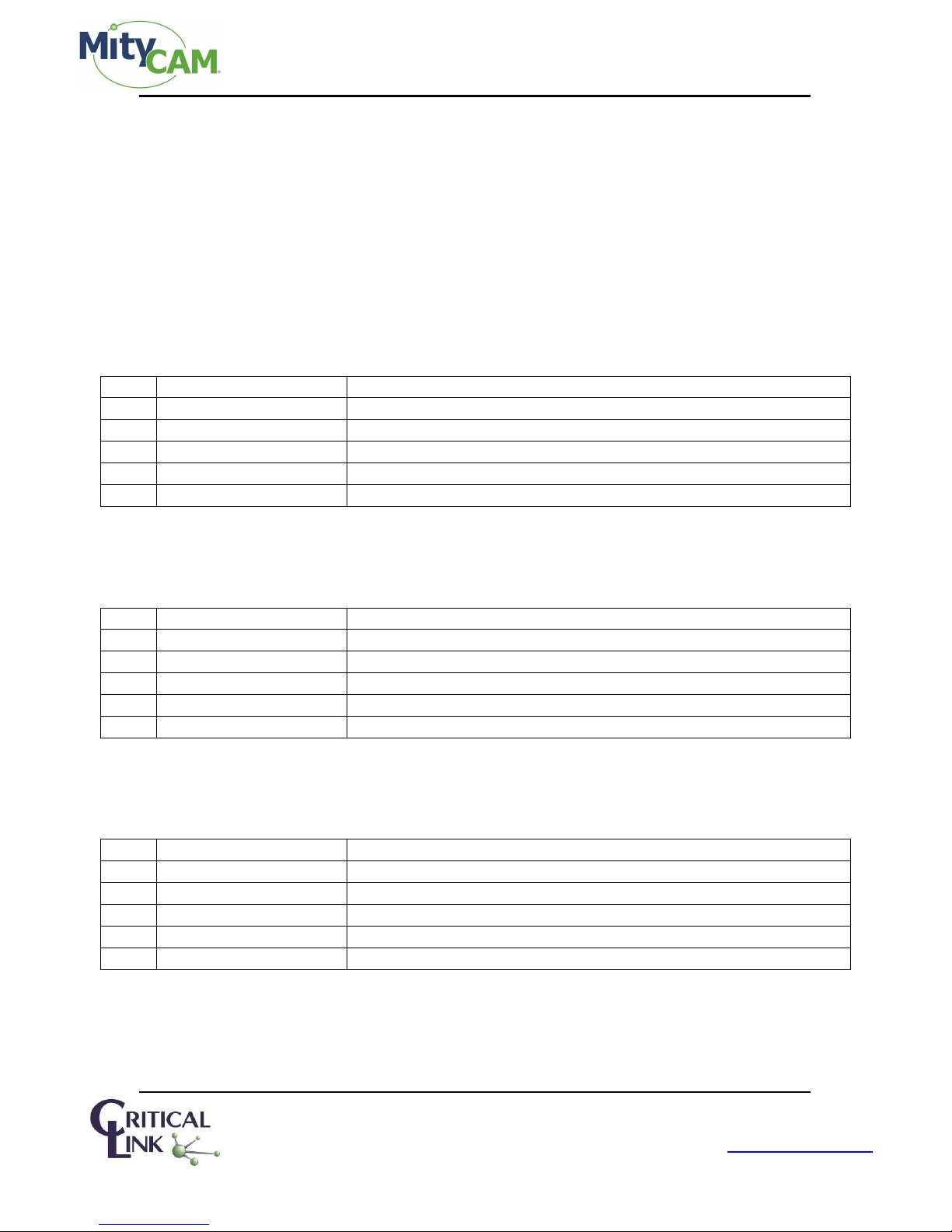
2 Continuous High Speed Operation via Camera Link
This section details setting up full resolution, high speed operation in each Camera Link configuration. Pay careful
attention to the clock and frame intervals that are being set. Failure to set an appropriate clock or frame interval
will overflow the FPGA with sensor data resulting in undefined output.
For each mode, SCLK must be adjusted. Please reference “Table 14 Maximum Supported SCLK Rates for Different
Camera Link Output Modes” in Section 9.
2.1 Expanded 8-bit Mode (8 bit x 10 pixels)
This mode offers the highest continuous frame-rate possible.
Table 2 Steps to Enter 8x10 Expanded Camera Link
2.2 Expanded 16-bit Mode (16 bit x 5 pixels)
This mode offers the highest continuous frame-rate possible while outputting all of the sensor data.
Table 3 Steps to Enter 16x5 Expanded Camera Link
2.3 Base 8-bit Mode (8 bit x 2 pixels)
This mode offers the highest continuous frame-rate possible.
Table 4 Steps to Enter 8x2 Base Camera Link
Page 7 of 27 60-000007
May 12, 2015
www.criticallink.com

MityCAM-B1910/B2521 User’s Manual
Step
Command
Comment
1
<SOMD 1>
Go to Base Camera Link output
2
<SBPP 1>
Go to 16 bpp output
3
<SCLK n>
See Table 14 in Section 9 for maximum SCLK.
4
<SFIT 0>
Set the frame-rate to the maximum supported
5
<STRT>
Begin continuously capturing
Step
Command
Comment
1
<SOMD 1>
Go to Base Camera Link output
2
<SBPP 2>
Go to 12 bpp output
3
<SSQRT 1>
Enable square root compression from 16 to 12 bits.
4
<SCLK n>
See Table 14 in Section 9 for maximum SCLK.
5
<SFIT 0>
Set the frame-rate to the maximum supported
6
<STRT>
Begin continuously capturing
2.4 Base 16-bit Mode (16 bit x 1 pixel)
This mode offers the highest continuous frame-rate possible.
Table 5 Steps to Enter 16x1 Base Camera Link
2.5 Base 12-bit Mode (12 bit x 2 pixels)
This mode offers the highest continuous frame-rate possible.
Table 6 Steps to Enter 12x2 Expanded Camera Link
When exiting this mode, ensure that <SSQRT 0> is applied to disable the square root compression.
3 Region of Interest
The region of interest is configurable between the sensors with some limitations.
3.1 Restrictions
The shared restrictions of ROI:
- ROI height must be an integer multiple of the vertical binning value
- ROI width must be an integer multiple of the horizontal binning value
- ROI width must be an integer multiple of 16
3.1.1 MityCAM-B2521
The maximum resolution of the sensor is 2560x2160.
The specific restrictions for the 2521:
- Start column must be even
- ROI must be centered on the middle row (columns don’t need to be centered; only rows)
- ROI height must be even
3.1.2 MityCAM-B1910
The maximum resolution of the sensor is 1920x1080.
There are no other specific restrictions for the MityCAM-B1910.
Page 8 of 27 60-000007
May 12, 2015
www.criticallink.com
MityCAM-B1910/B2521 User’s Manual
Minimum Frame Interval (row times)
Maximum Frame Interval (row times)
Rolling Shutter
Global Shutter
Rolling Shutter
Global Shutter
ROI
Height
(ROI
Height
+ 17)*2
262143 + ROI
Height
(ROI
Height
+ 262143)*2
3.2 MityViewer Restrictions
The ROI must meet the above specified requirements when using the MityViewer.
3.3 Important Note
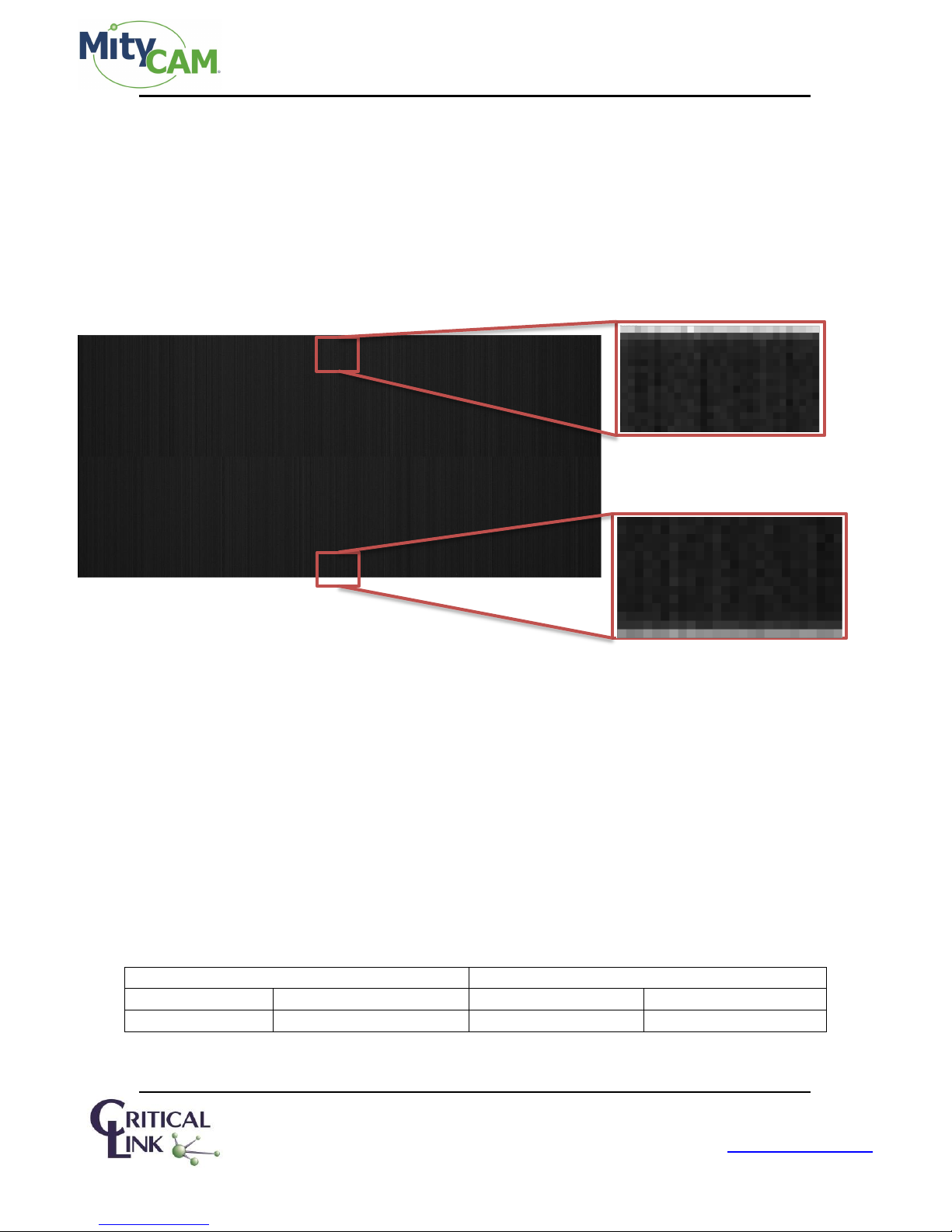
Rolling shutter starts exposure by sending a reset pointer row-by-row through the selected area. After some
amount of time, the rows are read out. When rows are not reset/read out, they will continue to accumulate
charge. Over time, with a reduced vertical ROI (such as requesting 1000 active rows for readout), the remaining
active rows (which are NOT being read out) will saturate and bloom into the area being readout. This results in
pixels of greater magnitude around the horizontal edge of the imaging area as in the example below:
Figure 2 Potential Leakage / Blooming with Reduced Vertical ROIs
4 Exposure & Frame Interval Time
Exposure and Frame Interval are integral multiples of “row times” from the sensor. Use the table in the section 5
“SCLK” to convert these row times to time values. Limits on exposure and frame interval times are sensitive to
the shutter mode (rolling vs. global) as well as triggering mode (internal vs. external).
4.1 Frame Interval
The Frame interval is dependent on the triggering method of the camera as well as the shutter mode. For
external triggering, the maximum frame interval time is set by the trigger input. For internal triggering, the
maximum frame interval time is defined by Table 7. For both internal and external triggering, the minimum
frame times are defined by the values in Table 8.
Table 7 Range of Frame Interval Times
Page 9 of 27 60-000007
May 12, 2015
www.criticallink.com
 Loading...