

1
Heavy Industrial PC
KUBE-3000 series
User Manual
Version 1.0

2
Table of contents
1.1 Description ............................................................................................................... 3
1.1.1 KUBE-3000 series ................................................................................................ 3
1.2 Ordering data .......................................................................................................... 4
1.2.1 Product ................................................................................................................ 4
1.2.2 Accessories .......................................................................................................... 4
2 Installation ........................................................................................................................ 5
2.1 Wall mount .............................................................................................................. 6
2.1.1 Wall mount .......................................................................................................... 6
2.2 Din rail mount .......................................................................................................... 7
2.2.1 Din rail mount dimension ................................................................................... 8
2.3 Interface ................................................................................................................... 8
2.3.1 I/O port ................................................................................................................ 8
2.3.2 Power connection ............................................................................................... 9
2.3.3 Serial Communication ....................................................................................... 10
2.4 Antenna ................................................................................................................. 11
3 Operation ........................................................................................................................ 12
3.1 LED status .............................................................................................................. 12
4 Maintenance ................................................................................................................... 13
4.1 Service panel.......................................................................................................... 13
4.2 Real time clock battery ......................................................................................... 14
4.3 CMOS/BIOS reset .................................................................................................. 15
4.4 Mass Storage (M.2) ............................................................................................... 16
4.5 Mass Storage (mSATA) .......................................................................................... 17
3
Overview
1.1 Description
MiTwell’s new KUBE series of embedded automation computers are highly rugged
design for heavy industrial application. KUBE series including pocket size, small
size and regular size with different level of processors to meet different kinds of
application in the Industry such as Equipment connectivity, Production process
monitoring, Environment Management, Process Visualization…etc. All models
provides flexible and time-to-market support in variety of applications.
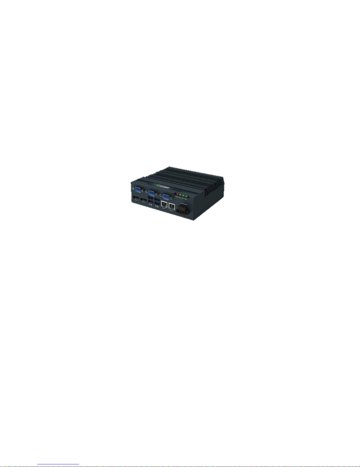
1.1.1 KUBE-3000 series
Compact size, ruggedize fan-less Box PC designed for heavy industrial
application with Intel® Apollo Lake family processor
Futures
Support Extended Temperature and Heavy Industrial EMC
Compact fan-less design, patented thermal solution
Easy for PPC integration by LVDS
Edge LED indication design
Expandable design by multiple interface
Support DIN-Rail, Wall Mounting, VESA Scheme
Removable service panel for easy maintenance

4
1.2 Ordering data
1.2.1 Product
Model No.
Description
Ordering No.
KUBE-3100
Intel® Apollolake Celeron N3350, 4xUSB,
3xCOM, 2xLAN, 24VDC
AS7-3040
1.2.2 Accessories
Catagory
Description
Ordering No.
Video adaptor
DP to VGA video adapter
TBD
DP to DVI-I video adapter
TBD
Mass Storage
(Wide Temp.)
M.2 SSD: 64GB
TBD
M.2 SSD: 128GB
TBD
M.2 SSD: 256GB
TBD
Memory
(KUBE-3000)
DDR3L SO-DIMM 4G
B473D522
DDR3L SO-DIMM 8G
B473D530
Mounting kit
Universal DIN rail adapter
TBD
Wall mounting kit
TBD
5
2 Installation
KUBE series IPC support varies way to mount. Please use the appropriate section
below to mount the IPC.
When installing the KUBE IPC in a cabinet, follow these general rules:
Verify clearances within the cabinet. Typically, leave at least 5 cm (2 in.) on
each side, with 12.7 cm (5 in.) on the connector side.
Drill all holes and make all cuts before beginning installation. Be sure to
protect already
Installed components from shavings during this procedure.
Supporting panels must be at least 14 gauge to provide proper support.
Make sure that there is adequate space around the heat sink to provide
sufficient cooling.
NOTE:
Exceeding the system temperature limits can result in performance degradation
of any or all components. It is therefore important that the ambient
temperature of the installation environment is kept within the system
temperature limits of your KUBE IPC.
6
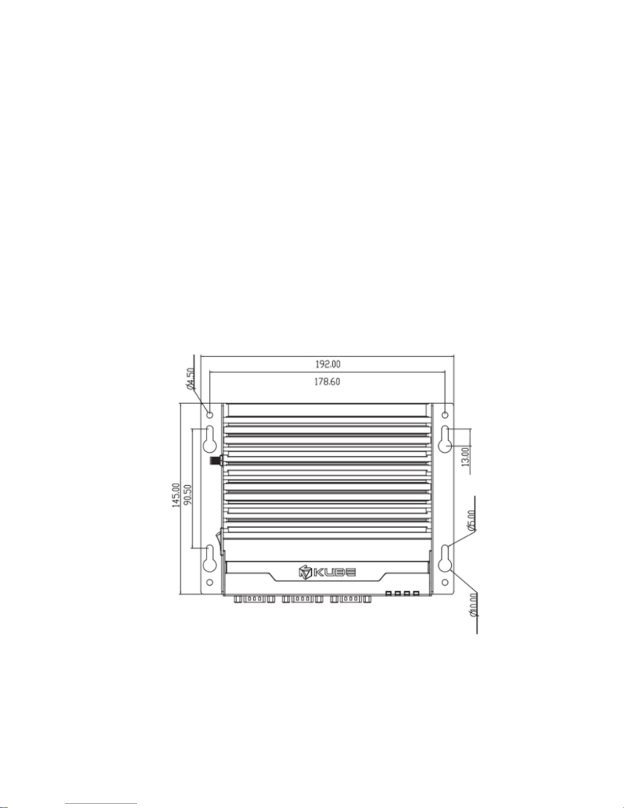
2.1 Wall mount
Installation
1. See the dimensions as below, and mark the locations of the holes on the
mounting surface.
2. Use the correct anchor type for the mounting surface and securely attach the
KUBE IPC to the wall. Ensure that the attaching hardware is in the small section of
the keyholes.
Removal
1. Remove power and disconnect cables to the IPC.
2. Loosen and remove the screws securing the IPC to the mounting surface.
2.1.1 Wall mount

7
2.2 Din rail mount
Install
1. Angle the KUBE IPC so the top edge of the mounting plate hangs on the top
edge of the DIN rail.
2. Rotate the KUBE IPC. down against the lower edge of the DIN rail. Press in until
the latch snaps closed.
Remove
3. Secure the device on the rail with clamps.
4. If necessary to remove, use a screwdriver to release the latch and rotate the
device away from the rail.

8
2.2.1 Din rail mount dimension
Above Din rail mount dimension follow by the Phoenix Contact UTA 107/30
2.3 Interface
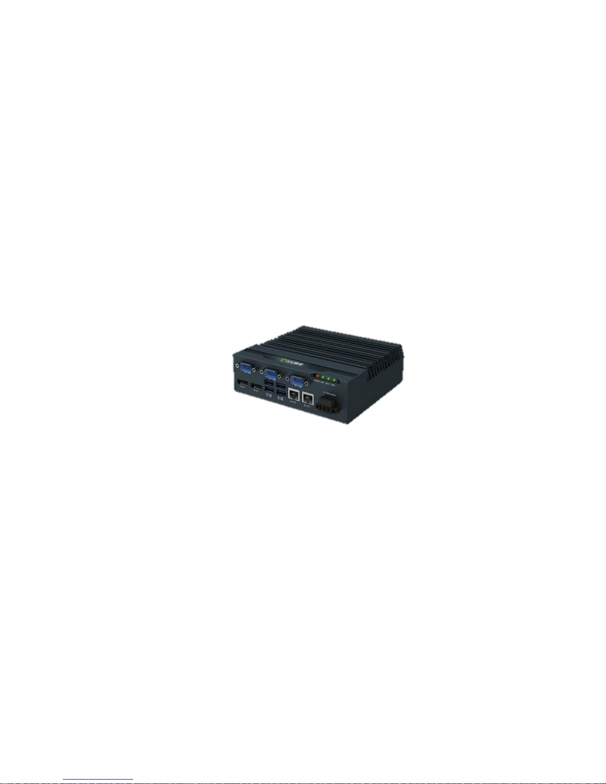
2.3.1 I/O port

9
After mounting KUBE IPC, make any necessary cable connections.
The available connectors are:
Ethernet (ETH): Two RJ45 connectors allow the computer to communicate on a
10/100/1000 Base-T Ethernet network.
Serial (COM): Three D-SUB 9 serial ports are available for use. Two ports are set
as RS-232 while one port is configurable as either RS-232, RS-422, or RS-485.
USB (USB): USB devices connect using Type-A connectors. Two ports are USB 2.0
and two are USB 3.0 ports
DisplayPort (DP): These ports connect the KUBE IPC to external digital displays
with a corresponding DisplayPort connector. If needed, you also can use Video
adaptor to other video interface, like DVI, HDMI…etc.
Mini PCIe: This internal slot allows installation of a mini PCIe card (see “Mass
storage” )
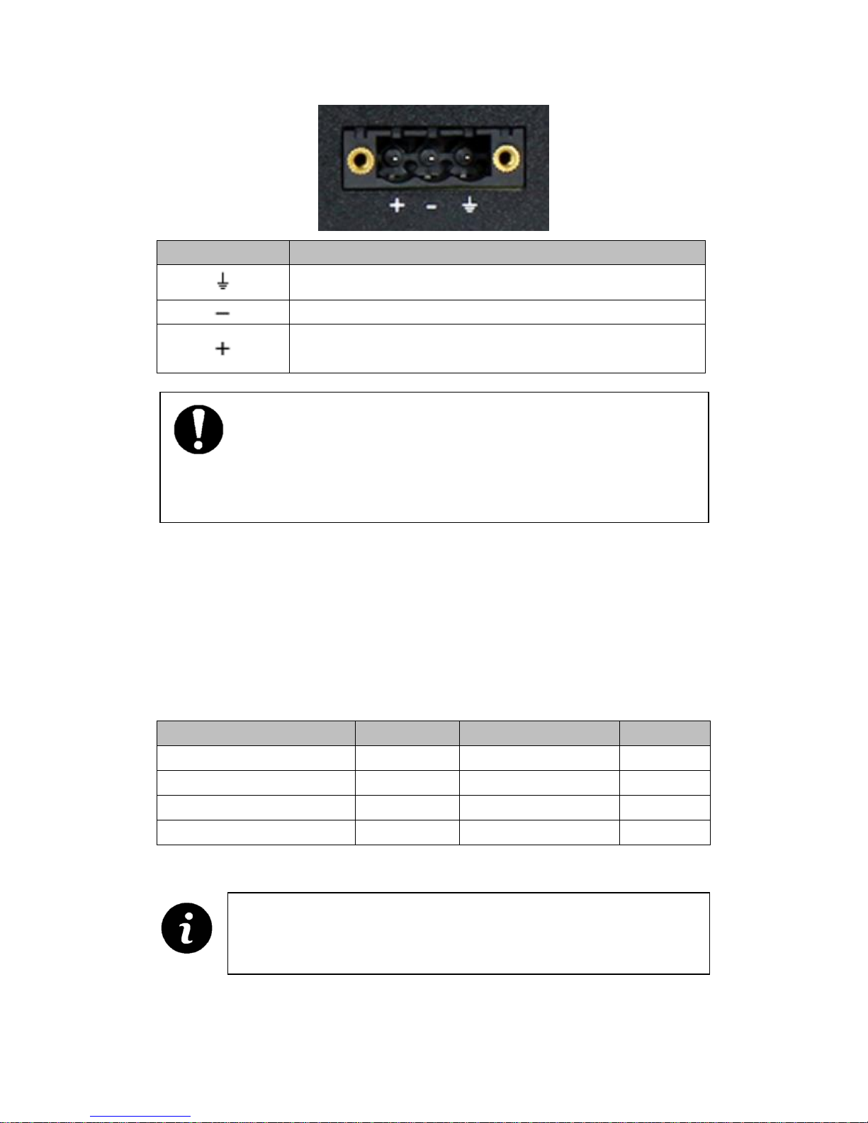
2.3.2 Power connection
A three-position, screw-type connector is provided for connecting power to the KUBE
3000/5000 series IPC.
Connect a power source to the included power connector. This connector supports
wire sizes from 0.2 to 2.5 mm² (24 to 12 AWG). Torque the wire-retaining screws in the
connector to 0.5 Nm (4.4 lbf-in.). Secure the connector to the KUBE IPC chassis.
USB 3.0 ports utilize a blue connector. USB 2.0 ports are black.
10
Pin No.
Description
Ground
0 V DC
24V DC ± 20 ﹪
2.3.3 Serial Communication
One D-SUB 9 connector can be configured to communicate on the RS-232, RS-422, or
RS-485 physical layer. The physical layer is set using the BIOS. The remaining
connectors are limited to RS-232 only. The KUBE-IPC is capable of the following
communication parameters:
Data bits
Parity
Stop bits
RS-232
7/8
None/Even/Odd
1/2
RS-422/485 Autotoggle RTS
8
None
2
RS-422/485 Autotoggle RTS
8
Even/Odd
1/2
RS-422/485 Manual RTS
7/8
None/Even/Odd
1/2
NOTE:
BIOS is set to boot on power, allowing the system to boot as soon as the power
plug is installed. This can be changed in the BIOS.
The table shows the capabilities of the IPC. Configuration of parameters
to communicate with a specific device is typically part of the software
tool performing the communication

11
The function of the pins in the D-SUB 9 connector varies with the different
configuration settings.
D-SUB 9 pin
RS-232
RS-422
RS-485
1
DCD
TXD-
TXD-/RXD-
2
RXD
TXD+
TXD+/RXD+
3
TXD
RXD+
- 4 DTR
RXD-
- 5 GND
GND
GND
6
DSR
- - 7
RTS
- - 8
CTS
- - 9
Ring indicator
-
-
2.4 Antenna
An optional factory-installed mini PCIe card is available to allow the KUBE-IPC to be
placed on a wireless network. Included with the installed card is an antenna (1) that
attaches to a connector on the side of the unit (2).
Since the KUBE IPC is often installed within an enclosure, it may be advisable to install
the antenna on the exterior of the enclosure rather than directly to the IPC. To do this,
an appropriate length antenna cable (3) must be purchased separately.
The antenna or antenna threads onto the KUBE IPC. For external antenna mounting,
route and secure the antenna cable appropriately within the enclosure.
12
3 Operation
3.1 LED status
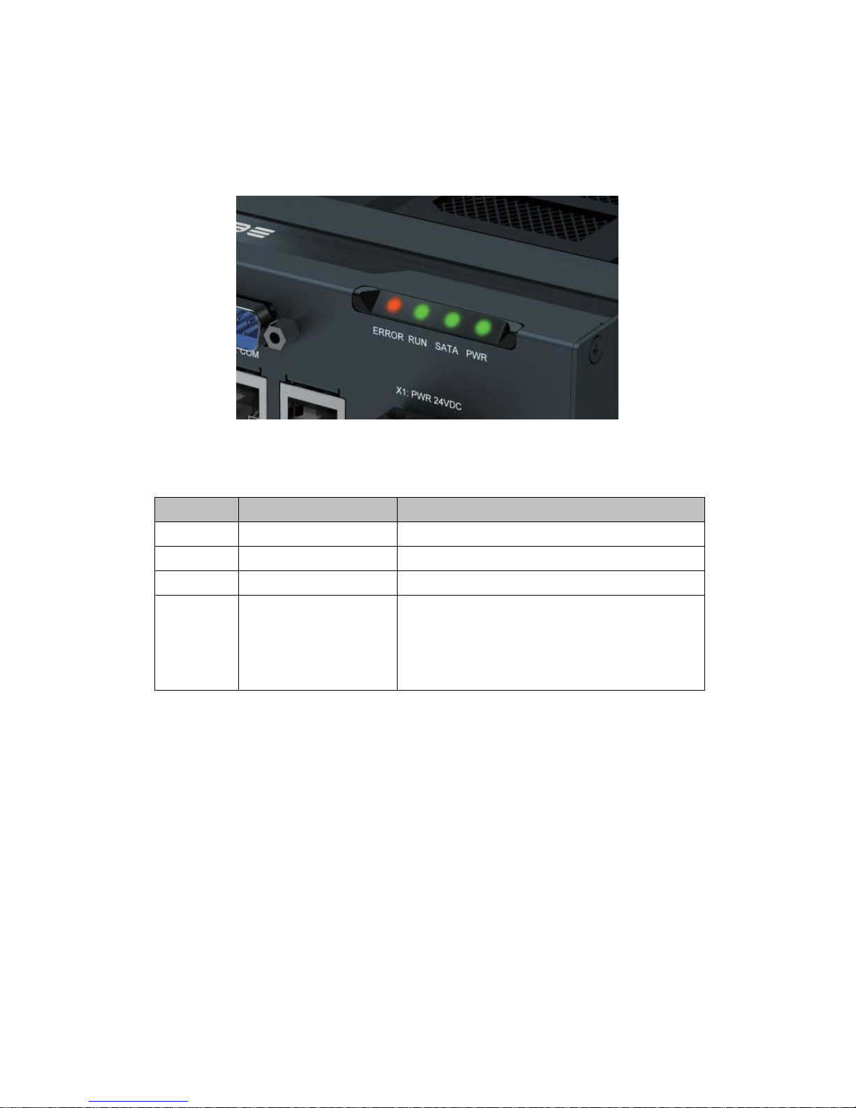
Four LEDs are provided on the KUBE IPC. These LEDs provide operating
information
LED
Indication
Description
PWR
Green
Power on
SATA
Flashes green
Data storage activity
RUN
Green
Reserved LED for future use
ERROR
Orange / Red
Orange: indicates processor is actively
thermal throttling
Red: indicates processor has shut down due
to overheating.
13
4 Maintenance
The KUBE-3000/5000 IPC has a removable service panel that allows access to the
mini PCIe card slot, configuration jumpers, and battery.
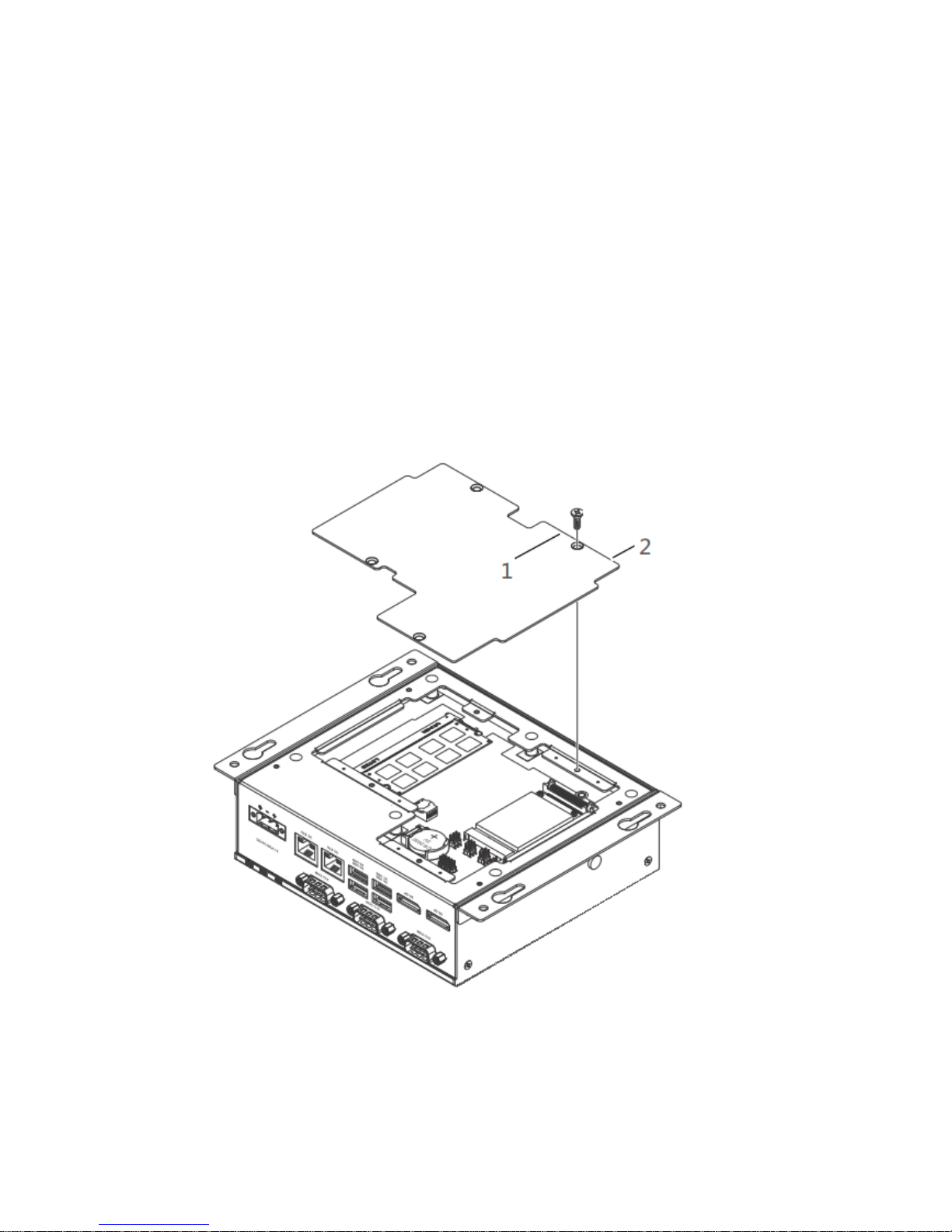
4.1 Service panel
1. Remove power from the KUBE IPC
2. Disconnect any cables, such as USB, Ethernet, etc., attached to the unit.
3. Place the unit on a flat surface with the heat sink down.
4. Loosen and remove the four screws (1) that hold the service panel (2) to the case
and remove the panel.
14
4.2 Real time clock battery
The battery supplies power to the real-time clock (RTC) and maintains the BIOS
settings in the KUBE IPC when the system is not connected to a 24 V DC power source.
If power is removed while the battery is discharged or removed, any user-defined BIOS
settings will be lost, and a “CMOS checksum error” message appears once power is
restored.
To account for user-defined BIOS settings, it is recommended that they be recorded
through photos or a separate document before the battery is depleted or removed.
Store the photos or documents on a different device so they are accessible in the event
of a boot failure. The battery is type BR2032. The battery has a typical life of five years
and may require replacement.
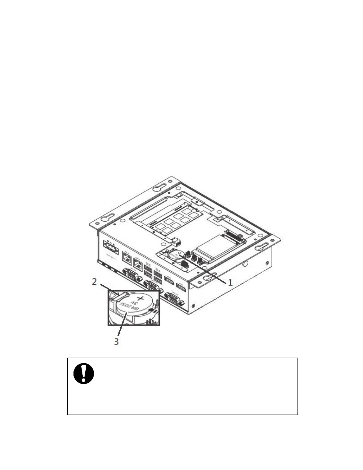
NOTE:
Note the orientation of the battery. One side should have a plus (+) symbol. The
replacement battery must be installed the same way.

15
To replace the battery:
1. Access the battery by removing the service panel.
2. Locate the battery holder (1).
3. To remove the battery, pull the retention clip (2) at the bottom of the battery
housing and the battery (3) will release from the housing.
4. To install a new battery, insert one end under the retention clip. Push the battery
toward the clip until the battery fully drops into the housing.
5. Reset the CMOS and BIOS using the appropriate jumpers
6. Reinstall the service panel or reattach the case to the display panel.
7. Reconnect the power connector and apply power. During the boot process, a
message will appear notifying the user that the CMOS and BIOS settings have been
reset to the factory defaults.
8. During the boot process, press the <F2> key to access the BIOS settings
9. Update the BIOS configuration with any appropriate user-defined requirements.
4.3 CMOS/BIOS reset
The CMOS is a small chip that stores the BIOS settings, date and time, and other
items of the IPC. It is powered by the real-time clock battery and, if the battery is
removed, will likely lose its settings. It can be reset to the factory defaults using a
reset button.

16
To reset the CMOS:
1. Remove the service panel
2. Remove the jumper JPA (1) from pins 1 and 2.
3. Place jumper between pins 2 and 3 for 3 seconds (reset position).
4. Remove jumper from pins 2 and 3, and reinstall on pins 1 and 2 (the run position).
5. Reinstall the service panel or reattach the case to the display panel.
6. Reconnect the power connector and apply power. During the boot process, a
message will appear notifying the user that the CMOS and BIOS settings have been
reset to the factory defaults.
7. During the boot process, press the <F2> key to access the BIOS settings
8. Update the BIOS configuration with any appropriate user-defined requirements.
4.4 Mass Storage (M.2)
The mass storage device is a solid-state drive (SSD) with an M.2 interface in the
chassis. You need to open the cover heatsink to install it.
To replace a drive:
1. Turn off the IPC and disconnect power.
2. Remove the screws on the heat sink
3: Locate the M.2 SSD (2260) and secures the drive in the socket.
4. To install, insert the drive into the connector and secure with the hardware
previously removed.
5. Position the heat sink in place and secure with the hardware previously removed.
Thermal pads between the board and heat sink may cause resistance
when removing the service panel.
NOTE:
Failure to ensure thermal pads are properly positioned may result in performance
loss.

17
4.5 Mass Storage (mSATA)
There is another mass storage option, solid-state drive (SSD) with an mSATA interface
(1) in the back of chassis. You need to open the service panel to install it.
To replace a drive:
1. Turn off the IPC and disconnect power.
2. Remove the screws of back service panel
3: You can see the mSATA socket.
4: Locate the mSATA SSD and secures the drive in the socket.
5. Position the service panel back in place and secure with the hardware previously
removed.
 Loading...