

Digimatic Indicator
Dial Indicator
Dial Test Indicator
Dial Indicator
Application and
Stand
New Products
ID-H
2046S
2109S-10
ID-N / ID-B
Small Tool Instruments and
Data Management
INDEX
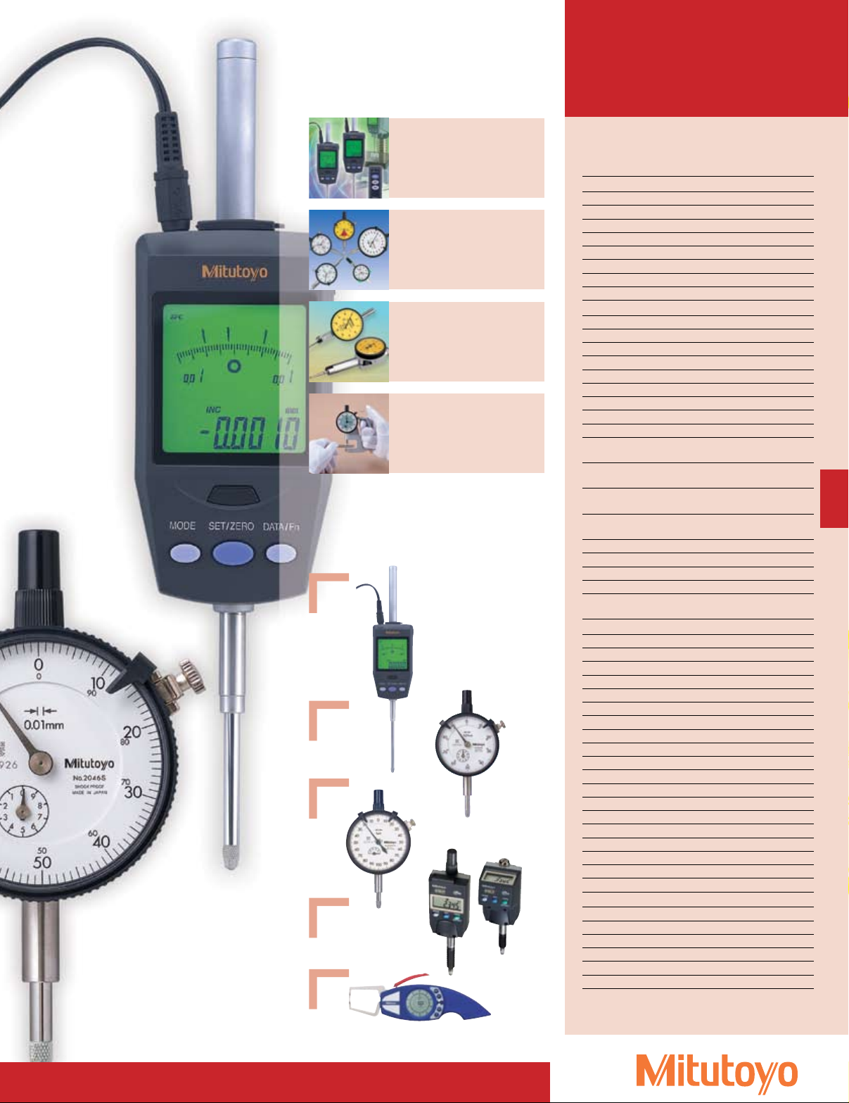
Digimatic Indicator
ABSOLUTE Digimatic Indicator ID-S F-2
ABSOLUTE Digimatic Indicator ID-U F-3
ABSOLUTE Digimatic Indicator ID-C F-4 – 9
ABSOLUTE Digimatic Indicator ID-H F-10
ABSOLUTE Digimatic Indicator ID-F F-11
ABSOLUTE Digimatic Indicator ID-N/B F-12
EC Counter F-13
Multi-Unit, Difference/Sum Unit F-13
Dial Indicator
Dial Indicators F-14
Dial Indicators F-15
Dial Indicators F-16 – 18
Dial Indicators F-19, 20, 22 – 26
Special Dial Indicators F-21
Dial Indicators F-27, 28
Dial Indicators F-29
Back Plunger Type Dial Indicator F-30, 31
Hicator, Signal Hicator F-32
Back, Contact Points
(Optional Accessories)
Spindle Lifting Lever and Cable
(Optional Accessories)
Color Spindle Caps
(Optional Accessories)
Limit Stickers
(Optional Accessories)
Dial Indicator Repair Tool Kit F-38
Dial Indicator Crystal Setter F-38
Dial Test Indicators F-39 – 43, 46
Pocket Type Dial Test Indicator F-44, 45
Contact Point and Clamp Holder
(Optional Accessories)
Dial Indicator Application
i-Checker F-48
UDT-2 Dial Gage Tester F-49
Calibration Tester F-49
Thickness Gages F-50 – 53
Light-Weight Dial Thickness Gage F-54
Pocket Thickness Gages F-54
Quick-Mini F-55
Digi-Derm F-56
MU-Gages F-57
Digimatic Caliper Gages F-58 – 62
Dial Tension Gage F-63
V-Block Set F-63
Magnetic V-Block F-63
Bench Gages F-64
Upright Gages F-65
Dial Snap Gages F-66
Snap Gages F-67
Female Screw Thread Comparator F-68
Dial Indicator & Magnetic Stand Set F-68
Stand
Magnetic Stand F-69
Dial Gage Stand F-70
Transfer Stand F-71
Precision Granite Stands F-72
Comparator Stand F-73
Heavy Duty Comparator Stand F-74
F-33 – 35
F-36
F-37
F-37
F-47
Caliper gage
F-1
i>À>ViÊÌÊ>Û`Ê
`ÀiVÌÊvÕiViÊvÊ
V>«}ÊvÀVi
>«}ÊÀ>}i
ä
£ä Óä Îä {ä xä Èä Çä nä ä £ää £Óä £{ä
£ä
£ä xä £ää Óxä xää Çxä £äää £Óxä £xää £Çxä Óäää
ä
£
Ó
Î
{
x
È
Ç
ä
À«Êi}ÌÊV®
/ÕÃ>`ÊÌiÃ
£ä
Óä
Îä
{ä
xä
ä
iÛ>ÌÊ®
ÀÀÀÊ®
,iÃÕÌÊvÊÀi«i>ÌÊ«>VÌÊÌiÃÌ
*ÌiÀÊ`iÛ>Ì
,iÃÕÌÊvÊi`ÕÀ>ViÊÌiÃÌ
Ü`iÀ>}iÊ>VVÕÀ>VÞ
7i}Ì
£xä}
`ÕÀ>ViÊÌiÃÌ}ÊÜÌÊV>
,Ì>ÌÊëii`\Ê£ÓäÀ«
Ó£ä-£äÊ`>Ê`V>ÌÀ
Ó£ä-£äÊ`>Ê`V>ÌÀ
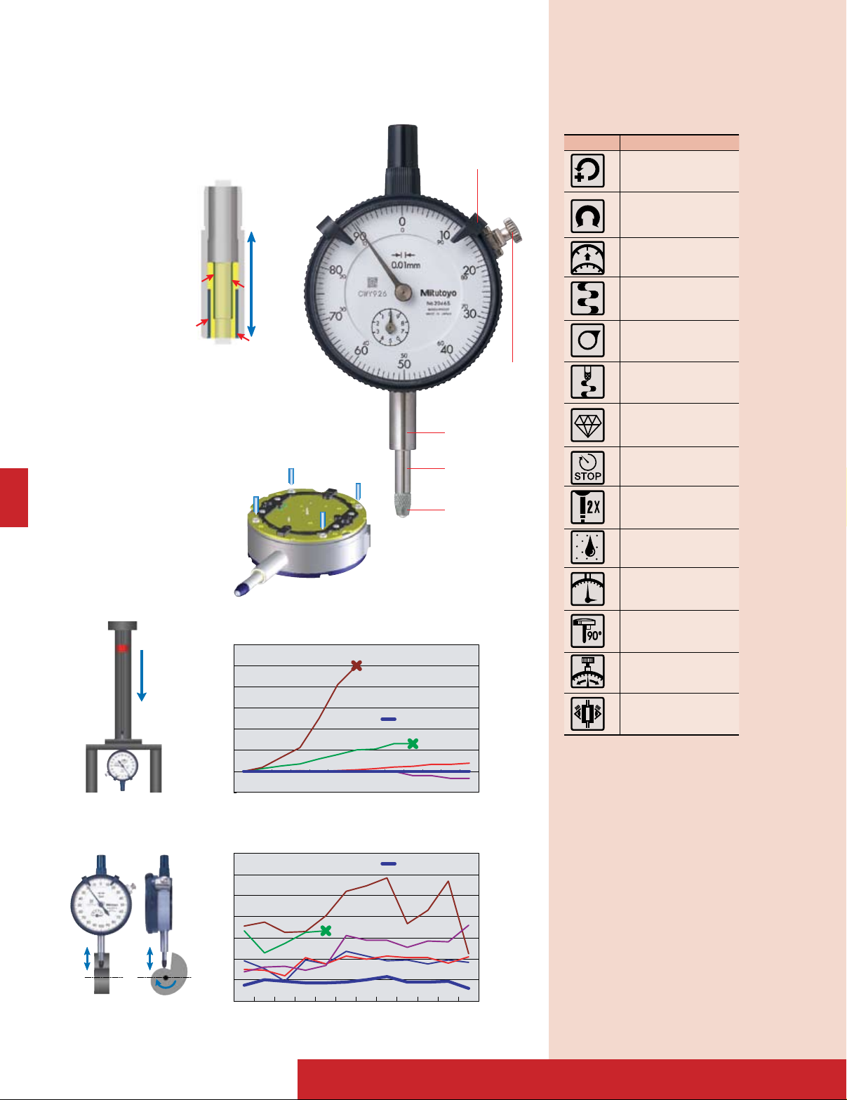
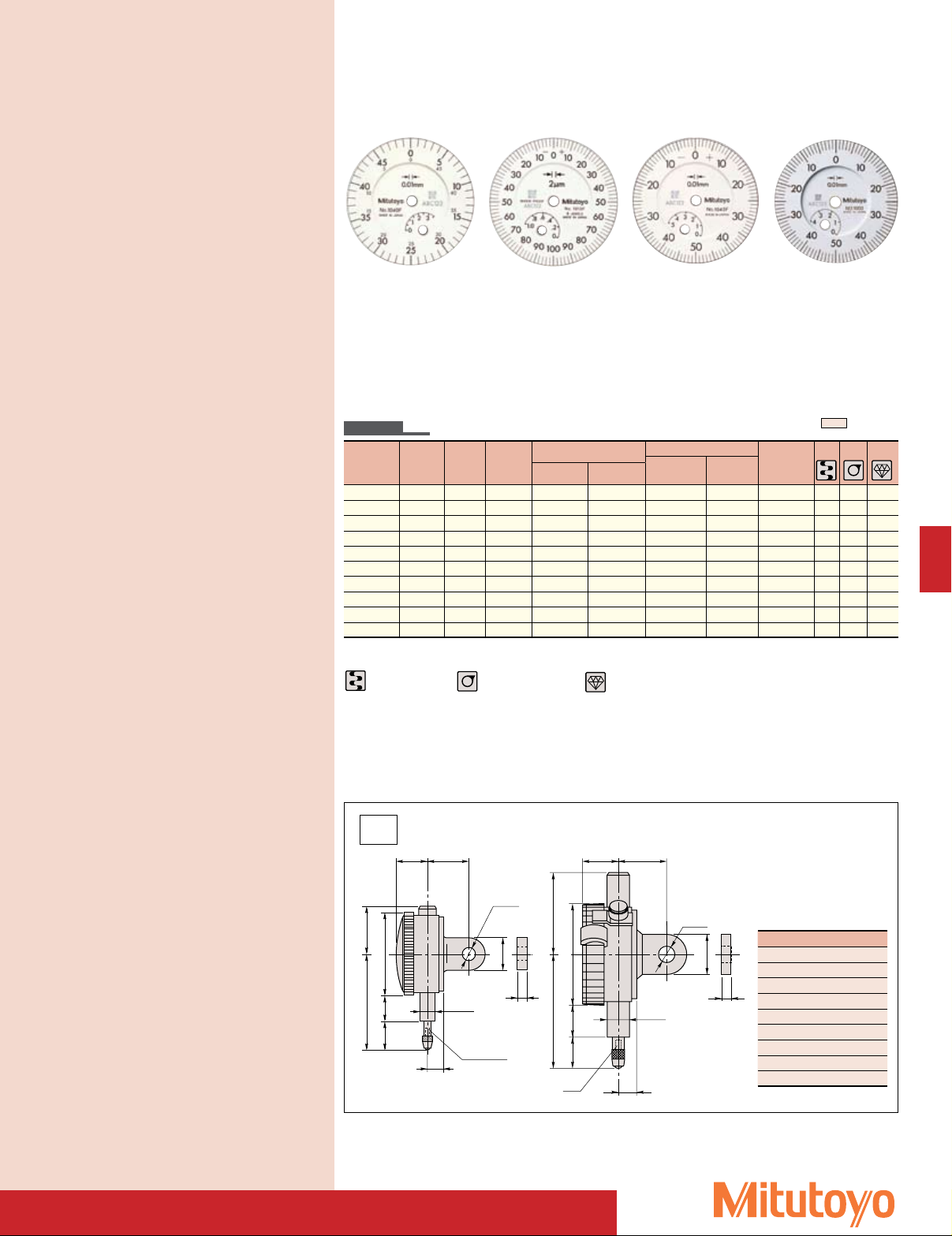
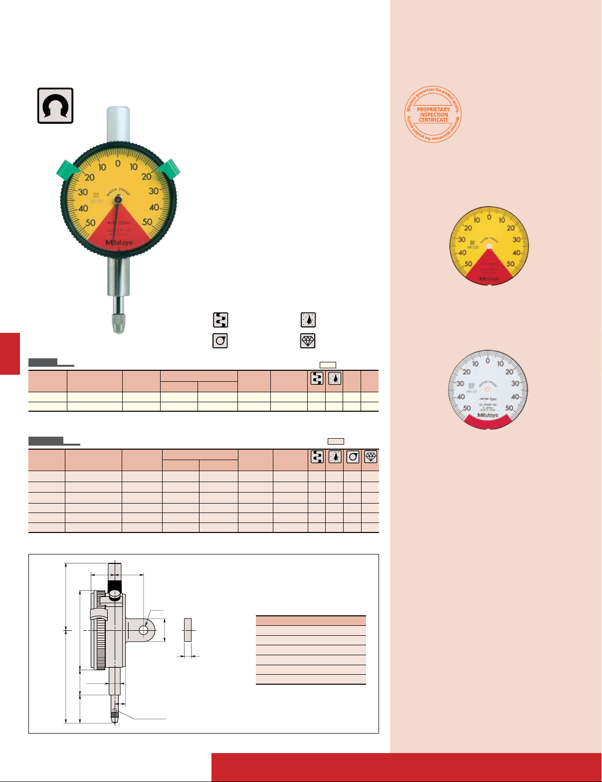
Dial Indicators
FEATURES: S Series
• Revolutionary stem-bush design for trouble
free stem clamping (longer clamping
range).
• No through screw-hole
on the frame for high
dust-resistance.
• Involute curved lifting lever for smooth
movement of spindle and dovetail joint for
tool-less connection.
• Grater rigidity in the bearing plate for
reducing the retracing error (20%) and
4-screw mounting for increasing impact
resistance.
Limit hand
Bezel clamp
Stem
Spindle
Contact point
Description of Icon
Icon Description
Reverse reading type
suitable for depth and step
measurement.
One revolution type for easy
and error-free reading
Double scale spacing type,
easy-on-the-eyes
Shockproof type
Waterproof type
With damper at lowest rest
point
Jeweled bearing type
Peak retaining type
Long stem type
F-14
Dustproof type
With coaxial revolution
counter
Back plunger type
Adjustable hand type
Double-face type
12.5
20
ø6.5
Thickness 5
ø8
0
-0.009
M2.5x0.45
7
A
B 15 ø31
16
30
.49" .75"
ø.26"
Thickness .25"
ø.375"
0
-.001
#4-48 Threads
.28"
A
B .59" ø1.22
.63"
1.18"
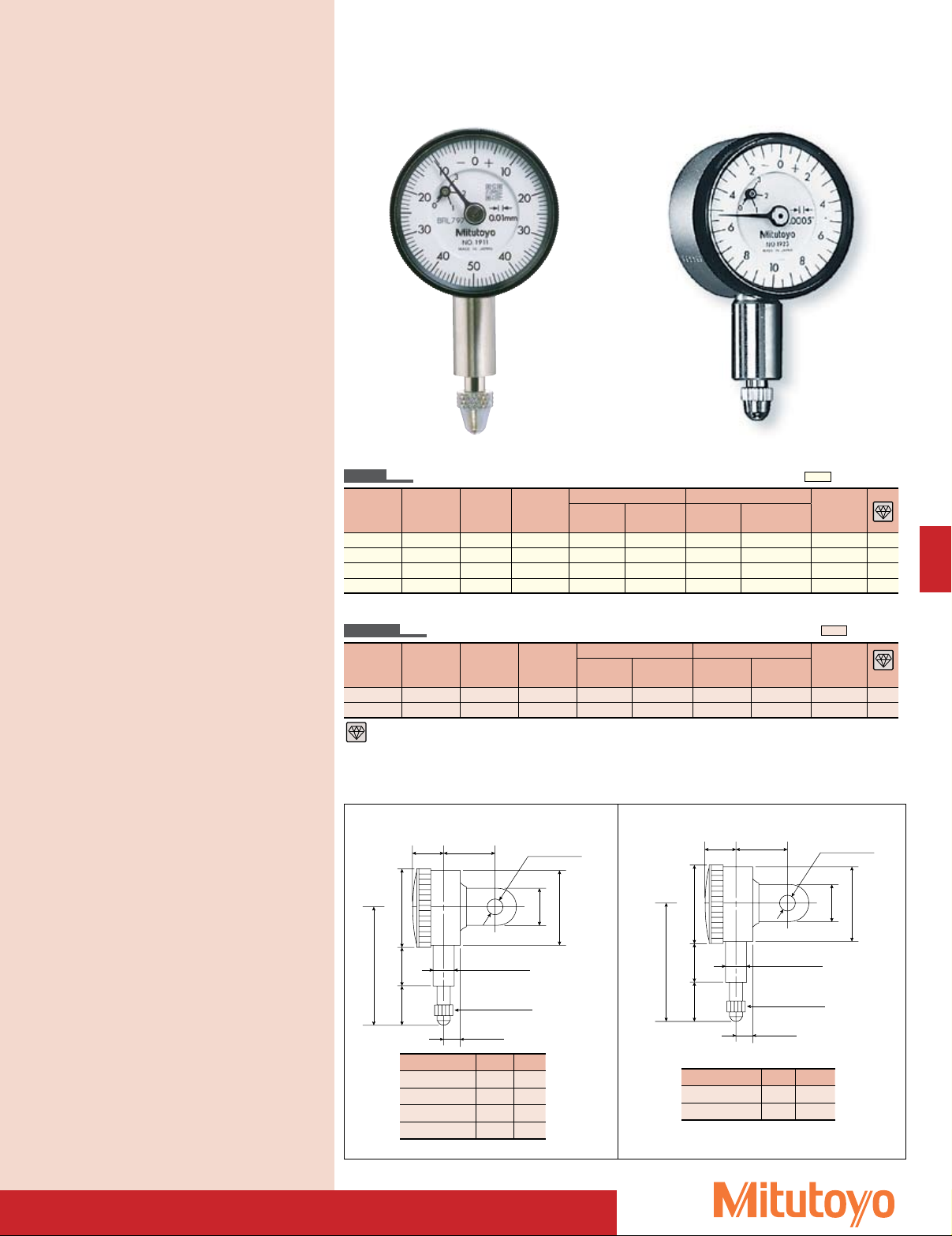
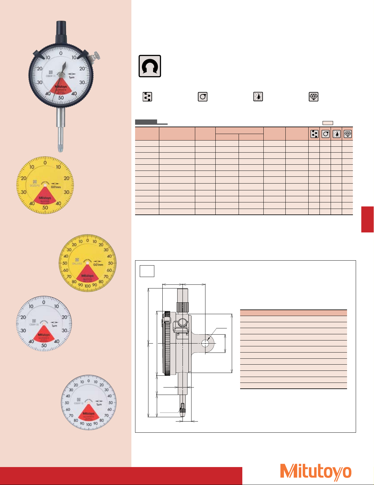
Dial Indicators
SERIES 0 - Compact type
1911
SPECIFICATIONS
Inch
Graduation Range Range/rev Dial reading
.0001” .01” .004” 0-2-0 1927-10 1927B-10 ±.0002” ±.0002”
.0001” .025” .01” 0-5-0 1925-10 1925B-10 ±.0002” ±.0002”
.0005” .05” .02” 0-10-0 1923 1923B ±.0005” ±.0005”
.001” .1” .04” 0-20-0 1921 1921B ±.001” ±.001”
Metric
Graduation Range Range/Rev Dial reading
0.002mm
0.01mm
Jeweled bearing type
0.5mm 0.2mm
2.5mm 1mm
Stem dia. 3/8", #4-48 UNF Thread
Order No. Accuracy
w/ lug Flat-back
Stem ø 8mm, M2.5 x 0.45 Thread
Order No. Accuracy
w/ lug Flat-back
0-100-0 1913-10 1913B-10 ±0.011mm ±0.011mm
0-50-0 1911 1911B ±0.011mm ±0.011mm
First 2.5
Rev
First 2.5
Rev
Overall
Accuracy
Overall
Accuracy
1923
ANSI/AGD type
Measuring
force
1.4N or less
1.4N or less
1.4N or less
1.4N or less
Measuring
force
1.4N or less
1.4N or less
4
4
—
—
ISO/JIS type
4
—
DIMENSIONS
Inch Model
Order Number A B
1927-10 1.46” .26”
1925-10 1.48” .28”
1923 1.51” .31”
1921 1.58” .37”
Unit: Inch Unit: mm
Metric Model
Order Number A B
1911 42 11.5
1913-10 39.5 9
F-15
Dial Indicators
#4-48UNF
16
ø41
13.3
AB
C
ø6.5
6.6
14.5 19
6.35
3/8”
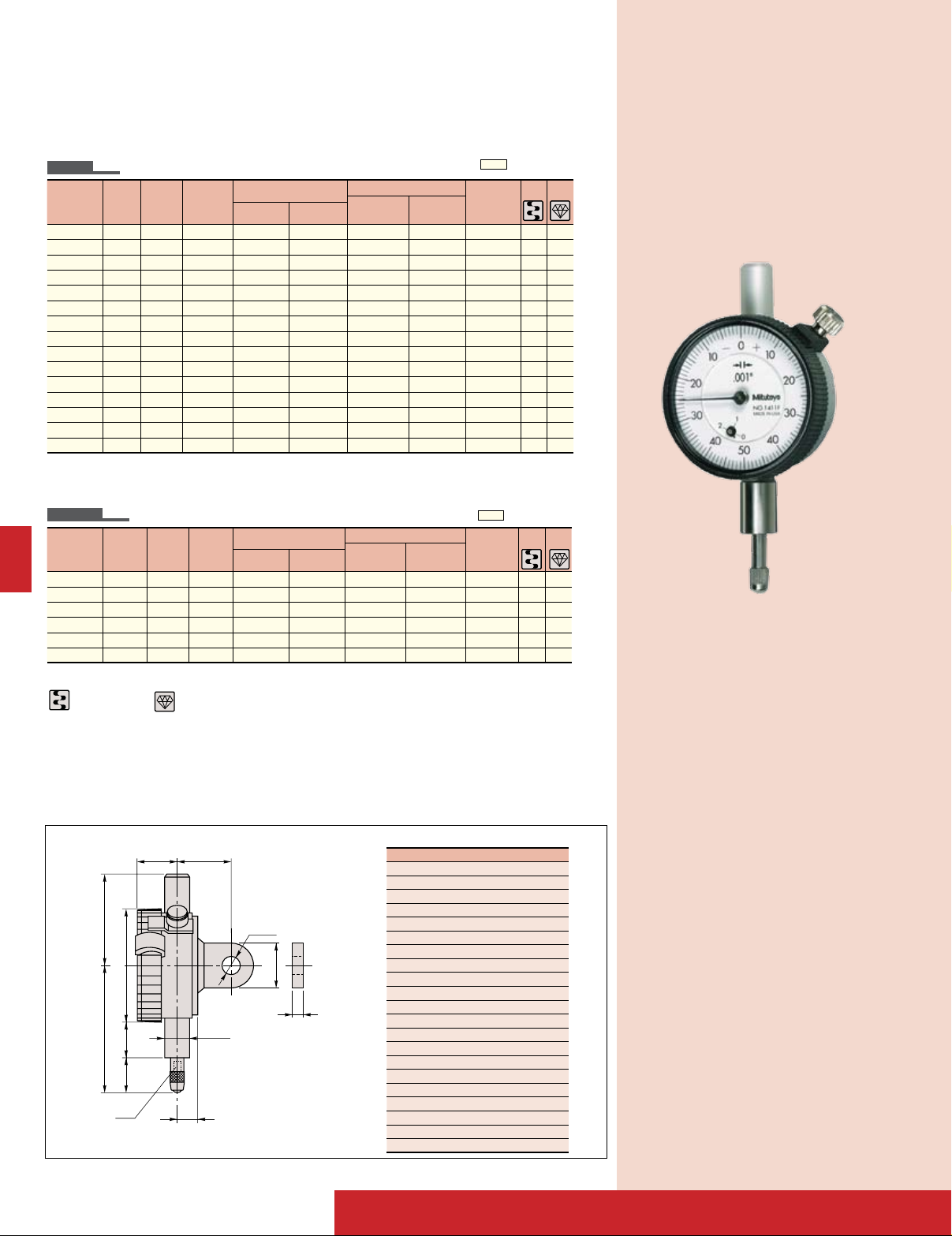
SERIES 1
SPECIFICATIONS
Inch
Graduation Range
.0001" .025" .01" 0-10 1802F-10 1802FB-10
.0001" .025" .01" 0-5-0 1803F-10 1803FB-10
.00025" .05" .02" 0-20 1470F 1470FB
.00025" .05" .02" 0-10-0 1471F 1471FB
.0005" .075" .03" 0-30 1570F-10 1570FB-10
.0005" .075" .03" 0-15-0 1571F-10 1571FB-10
.0005" .1" .04" 0-40 1670F 1670FB
.0005" .1" .04" 0-20-0 1671F 1671FB
.0005" .125" .05" 0-50 1506F 1506FB
.0005" .125" .05" 0-25-0 1507F 1507FB
.001" .125" .05" 0-50 1780F 1780FB
.001" .125" .025" 0-25-0 1781F 1781FB
.001" .25" .1" 0-100 1410F 1410FB
.001" .25" .1" 0-100 1410F-10 1410FB-10
.001" .25" .1" 0-50-0 1411F 1411FB
Metric
Graduation Range
0.002mm 0.5mm 0.2mm 0-20 1010F-11 1010FB-11
0.002mm 0.5mm 0.2mm 0-10-0 1011F-11 1011FB-11
0.01mm 2.5mm 1mm 0-100 1230F-01 1230FB-01
0.01mm 2.5mm 1mm 0-50-0 1231F-01 1231FB-01
0.01mm 5mm 1mm 0-100 1044F-01 1044FB-01
0.01mm 5mm 1mm 0-50-0 1045F-01 1045FB-01
Stem dia. 3/8" #4-48 UNF Thread
Dial
reading
Order No.
(W/Lug) (Flat-back)
Order No.
(W/Lug) (Flat-back)
Range
Dial
/ Rev
reading
Metric - ANSI Standard Stem dia. 3/8"#4-48 UNF Thread yellow dial face
Range
/Rev
ANSI/AGD type
Accuracy
First 2.5 Rev
Overall
Accuracy
Measuring
force
±.0001" ±.0001" 1.4N or less
±.0001" ±.0001" 1.4N or less
±.00025" ±.00025" 1.4N or less
±.00025" ±.00025" 1.4N or less
±.0005" ±.0005" 1.4N or less
±.0005" ±.0005" 1.4N or less
±.0005" ±.0005" 1.4N or less
±.0005" ±.0005" 1.4N or less
±.0005" ±.0005" 1.4N or less
±.0005" ±.0005" 1.4N or less
±.001" ±.001" 1.4N or less
±.001" ±.001" 1.4N or less
±.001" ±.001" 1.4N or less
±.001" ±.001" 1.4N or less
±.001" ±.001" 1.4N or less
ANSI/AGD type
Accuracy
First 2.5 Rev
Overall
Accuracy
Measuring
force
±0.002mm - 1.4N or less
±0.003mm - 1.4N or less
±0.01mm - 1.4N or less
±0.01mm - 1.4N or less
±0.01mm ±0.013mm 1.4N or less
±0.01mm ±0.013mm 1.4N or less
4 4
4 4
4
4
4
1411F
4 4
4 4
Shockproof type
DIMENSIONS
Jeweled bearing type
Unit: mm
Order No. A B C
1802F(B)-10 28.1 43.4 9.6
1803F(B)-10 28.1 43.4 9.6
1470F(B) 28.1 42.7 8.9
1471F(B) 28.1 42.7 8.9
1570F(B)-10 28.1 43.4 9.6
1571F(B)-10 28.1 43.4 9.6
1670F(B) 28.1 44.2 10.4
1671F(B) 28.1 44.2 10.4
1506F(B) 28.1 45.2 11.4
1507F(B) 28.1 45.2 11.4
1780F(B) 28.1 45.2 11.4
1781F(B) 28.1 45.2 11.4
1410F(B) 33.2 48.7 14.9
1410F(B)-10 33.2 48.7 14.9
1411F(B) 33.2 48.7 14.9
1010F(B)-11 28.1 43.4 9.6
1011F(B)-11 28.1 43.4 9.6
1230F(B)-01 28.1 44.2 10.4
1231F(B)-01 28.1 44.2 10.4
1044F(B)-01 33.2 46.7 12.9
1045F(B)-01 33.2 46.7 12.9
F-16
Ó°xä°{x
£ääÎ
£È
©{£
ÎÓ°x
©È°x
Ç
£{°x£Î Óä£x
x
£È
Óäΰx
©È°x
Ó°xÝä°{x
x°Î
°x£Ó ©ÎÈ
x
©n
Êä
ä°ää
©n
Êä
ä°ää
Dial Indicators
SERIES 1
1040F 1013F
Metric
Graduation Range
Stem ø 8mm M2.5 X 0.45 Thread
Dial
reading
Order No.
(W/Lug) (Flat-back)
Range
/ Rev
0.001mm 1mm 0.2mm 0-100-0 1109F 1109FB
0.002mm 1mm 0.2mm 0-100-0 1013F 1013FB
0.005mm 3.5mm 0.5mm 0-50 1124F 1124FB
0.01mm 3.5mm 0.5mm 0-50 1040F 1040FB
0.01mm 3.5mm 0.5mm 0-25-0 1041F 1041FB
0.01mm 4mm 1mm 0-50-0 1003B 1003B
0.01mm 5mm 1mm 0-100 1044F 1044FB
0.01mm 5mm 1mm 0-100 1044F-60 1044FB-60
0.01mm 5mm 1mm 0-100 1044F-10 1044FB-10
0.01mm 5mm 1mm 0-50 1045F 1045FB
Shockproof type
Waterproof type
Jeweled bearing type
1045F
Accuracy
First 2.5 Rev
Overall
Accuracy
Measuring
force
±0.001mm ±0.007mm 1.5N or less
±0.002mm ±0.01mm 1.5N or less
±0.005mm ±0.013mm 1.4N or less
±0.01mm ±0.013mm 1.5N or less
±0.01mm ±0.013mm 1.5N or less
±0.01mm ±0.013mm 1.5N or less
±0.01mm ±0.013mm 1.5N or less
±0.01mm ±0.013mm 2N or less
±0.01mm ±0.013mm .4N or less
±0.01mm ±0.013mm 1.4N or less
1003
ISO/JIS type
4 4
4 4
4
4
4
DIMENSIONS
ISO/JIS
Type
Order No. A B C
1040F 46 13 12.5
1041F 46 13 12.5
F-17
1044 47.5 13 14
1044F-10 47.5 13 14
1044F-60 57 11.5 25
1045F 47.5 13 14
1124F 46 13 12.5
1013F 49 13 15.5
1109F 49 13 15.5
Unit: mm
ø
41
32.5 (28.1)
B (13.3)
C (10.9)
A (44.7)
20
(19)
16
(3/8”)
M2.5×0.45
(# 4-48UNF)
5
(6.35)
ø
6.5
7
ø8
0
-0.009
Dial Indicators
Jeweled bearing type
Shockproof type
Waterproof type
Dustproof type
Jeweled bearing type
Waterproof type
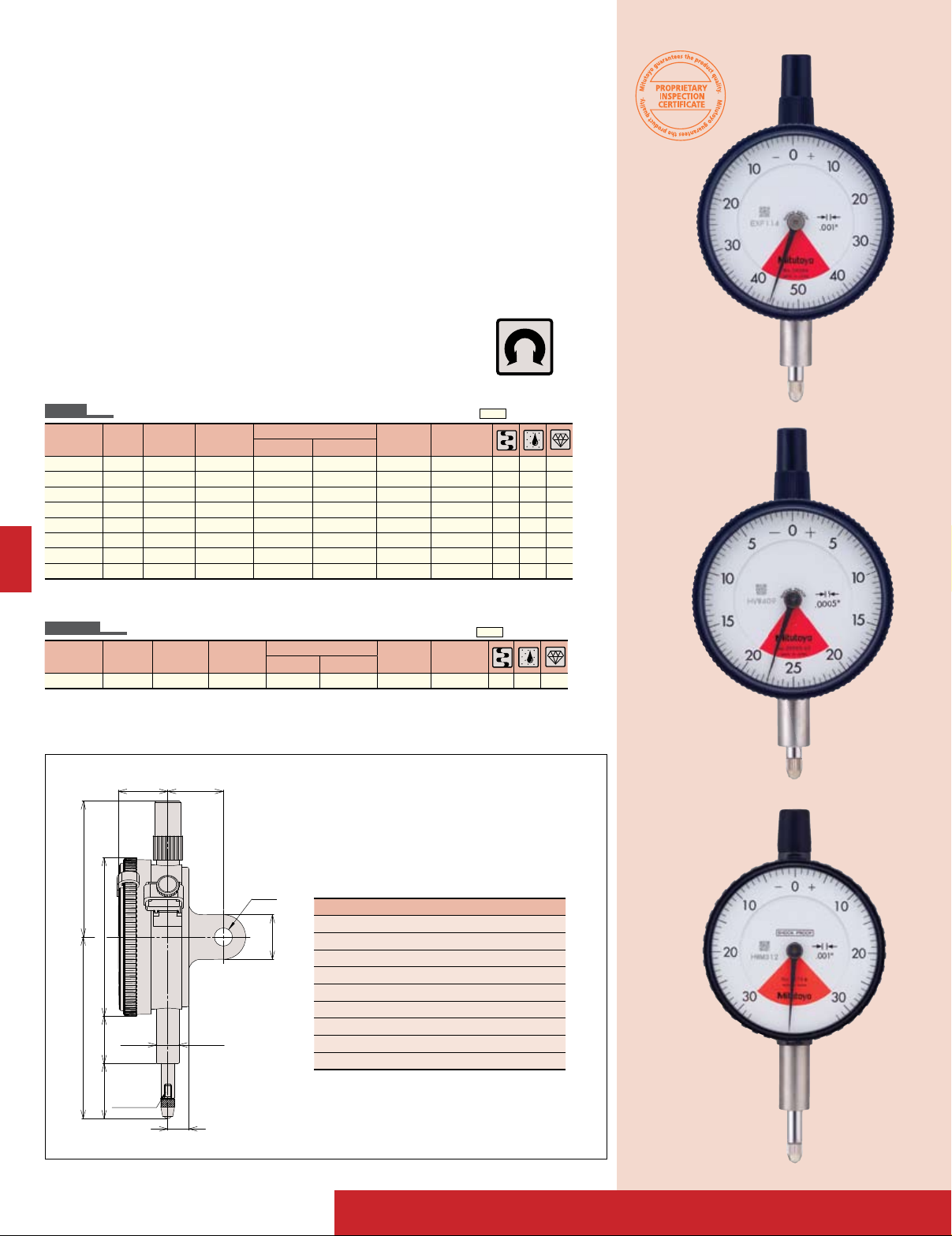
SERIES 1 — Compact One Revolution Type for Error-free Reading
Unlike many other dial indicators, the onerevolution dial indicator literally shows the
entire spindle travel or range as one sweep
One revolution type
of the hand, eliminating the possibility of
reading errors due to miscounting the multiple revolutions. With one-revolution dial
indicators, "within tolerance" and "out-oftolerance" can never misinterpreted
An unique shock-proof mechanism is
incorporated, providing improved immunity
to shock due to sudden spindle retraction
caused by high impact.
1929F-62
SPECIFICATIONS
Inch
Graduation
Range
(range/full stroke)
.0001” .006” / .0079” 3-0-3 1910F-72 1910FB-72 ±.0001”
.0005” .04” / .055” 20-0-20 1909F-62 1909FB-62 ±.0005”
Metric
Graduation
Range
(range/full stroke)
0.001mm 0.1mm / 0.14mm 50-0-50 1900F 1900FB ±0.005mm
0.001mm 0.1mm / 0.14mm 50-0-50 1900F-60 1900FB-60 ±0.006mm
0.001mm 0.1mm / 0.14mm 50-0-50 1900F-62 1900FB-62 ±0.006mm
0.01mm 1mm / 1.4mm 50-0-50 1929F 1929FB ±0.011mm
0.01mm 1mm / 1.4mm 50-0-50 1929F-60 1929FB-60 ±0.011mm
0.01mm 1mm / 1.4mm 50-0-50 1929F-62 1929FB-62 ±0.011mm
Stem dia. 3/8", #4-48 UNF Thread
Dial reading
Order No.
w/ lug Flat-back
Stem ø 8mm, M2.5 x 0.45 Thread
Dial reading
Order No.
w/ lug Flat-back
Accuracy
Accuracy
DIMENSIONS
ANSI/AGD type
Measuring
force
1.4N or less
1.4N or less
4 4
4 4
— —
— —
— —
ISO/JIS type
Measuring
force
1.5N or less4— —
1.5N or less4—
1.5N or less
4 4
4 4
—
1.4N or less4— — —
1.4N or less4—
1.4N or less
4 4
4
— —
Unit: mm
1929F
1929F-60
1929F-62
1900F
1900F-60
1900F-62
4
4
—
Optional Accessories
––––––: Backs (See page F-33.)
––––––: Contact points (See page F-34.)
F-18
Order No. A B C
1929F 47.5 13 14
1929F-60 55.5 11.5 23.5
1929F-62 47.5 13 14
1900F 53.5 16 17
1900F-60 54.5 11.5 22.5
1900F-62 53.5 16 17
( ): ANSI / AGD type
ø6.5
M2.5×0.45
16
D 20
øC
F E
B
7.6
øH
A
ø8
0
-0.009
Waterproof type
Jeweled bearing type
Shockproof type
Dustproof type
Dial Indicators
SERIES 2 — Standard One Revolution Type for Error-free Reading
One revolution type.
2929S
2929S-60
2929S-62
2900S-10
SPECIFICATIONS
Metric
Graduation
0.001mm 0.08mm / 0.1mm 40-0-40 2900S-10 2900SB-10 ±0.003mm
0.001mm 0.08mm / 0.1mm 40-0-40 2900S-70 2900SB-70 ±0.003mm
0.001mm 0.08mm / 0.1mm 40-0-40 2900S-72 2900SB-72 ±0.003mm
0.001mm 0.16mm / 0.2mm 80-0-80 2901S-10 2901SB-10 ±0.004mm
0.01mm 0.8mm / 1mm 40-0-40 2929S 2929SB ±0.009mm
0.01mm 0.8mm / 1mm 40-0-40 2929S-60 2929SB-60 ±0.009mm
0.01mm 0.8mm / 1mm 40-0-40 2929S-62 2929SB-62 ±0.009mm
0.01mm 1.6mm / 2mm 80-0-80 2959S 2959SB ±0.013mm
0.01mm 0.5mm / 0.7.mm 25-0-25 — 2971* ±0.010mm
0.01mm 1mm / 1.4mm 50-0-50 — 2972* ±0.012mm
0.02mm 1.6mm / 2mm 80-0-80 — 2973* ±0.016mm
0.1mm 4mm / 10mm 2-0-2 2928S 2928SB ±0.040mm
* Flat back type only. (Lug-on-center back is not available.)
Stem ø 8mm, M2.5 x 0.45 Thread
Range
(range/full stroke)
Dial
reading
Order No.
w/ lug Flat-back
Accuracy
DIMENSIONS
ISO/JIS
Type
ISO/JIS type
Measuring
force
1.4N or less4— —
2.0N or less
4 4
2.0N or less4—
1.4N or less4— —
—
4 4
4
4
4
2.0N or less4— — —
2.0N or less
4 4
2.0N or less4—
— —
4
—
1.4N or less4— — —
1.4N or less4—
1.4N or less4—
1.4N or less4—
—
4
—
4
—
4
1.4N or less4— — —
Unit: mm
2900S-10
2900S-70
2900S-72
Optional Accessories
––––––: Backs (See page F-33.)
––––––: Contact points (See page F-34.)
2959S
2901S-10
Order No. A B C D E F H
2971 43.2 65.6 55.6 16.2 21 16.8 55
2972 43.2 66.0 55.6 16.2 21 17.2 55
2973 43.2 66.3 55.6 16.2 21 17.5 55
2929S 48.8 65.2 57 17.7 12.3 29.2 52
2929S-62 48.8 65.2 57 17.7 16.9 19.8 52
2929S-60 48.8 70 57 17.7 12.3 29.2 52
2959S 48.8 65.2 57 17.7 16.9 19.8 52
2900S-10 48.8 66 57 17.7 16.9 20.6 52
2900S-72 48.8 66 57 17.7 16.9 20.6 52
2900S-70 48.8 67 57 17.7 12.3 26.2 52
2901S-10 48.8 66.1 57 17.7 16.9 20.7 52
2928S 48.8 65.2 57 17.7 16.9 19.8 52
F-19
Dial Indicators
ø.26”
#4-48 UNF
.63”
D
.75”
øC
E F
B
.3”
A
ø3/8”
SERIES 2 — Standard One Revolution Type for Error-free Reading
FEATURES
• An unique shock-proof mechanism
is incorporated, providing improved
immunity to shock due to sudden spindle
retraction caused by high impact.
• The crystal is hard coated for durability and
scratch resistance.
• Approximately 40% lighter than the
conventional dial indicator.
• Provided with an improved resistance to
shop floor contaminants such as water
and dust.
• Due to the spindle bushing being offset
from the stem, spindle movement will not
be hindered or jammed when clamping
along the stem.
• A pair of limit hands are provided for quick
and easy tolerance judgment (GO/±NG).
SPECIFICATIONS
Inch
Graduation Range
.0001” .008” .01” 4-0-4 2910S-10 2910SB-10 ±.0001”
.0001” .008” .01” 4-0-4 2910S-72 2910SB-72 ±.0001”
.0005” .04” .05” 20-0--20 2909S-62 2909SB-62 ±.0005”
.0005” .02” .028” 10-0-10 — 2976* ±.0005”
.0005” .04” .055” 20-0-20 — 2977* ±.0005”
.001” .06” .079” 30-0-30 — 2978* ±.001”
.001” .08” .1” 40-0-40 2908S 2908SB ±.001”
.001” .08” .1” 40-0-40 2908S-62 2908SB-62 ±.001”
*Flat back type only. (Lug-on-center back is not available.)
Stem 3/8" dia. , #4-48 UNF Thread
Range/full
stroke
Dial reading
Order No.
w/ lug Flat-back
Accuracy
One revolution type.
Measuring
force
1.8N or less
2.5N or less
2.5N or less
1.4N or less
1.4N or less
1.4N or less
1.8N or less
2.5N or less
2908S
ANSI/AGD type
4 4
4 4 4
4 4
4 4
4 4
4 4
4
4 4
Metric
Graduation Range
0.001mm 0.08mm 0.1mm 40-0-40 2900S-73 2900SB-73 ±0.003mm
*Flat back type only. (Lug-on-center back is not available.)
Stem 3/8" dia. , #4-48 UNF Thread Yellow Dial Face
Range/full
stroke)
Dial reading
Order No.
w/ lug Flat-back
DIMENSIONS
Order No. A B C D E F
2976 1.70 2.55 2.19 .64 .62 .83
2977 1.70 2.56 2.19 .64 .64 .83
2978 1.70 2.57 2.19 .64 .65 .83
2908S 1.92 2.08 2.24 .7 .43 .54
2908S-62 1.92 2.08 2.24 .7 .43 .54
2909S-62 1.92 2.04 2.24 .7 .36 .54
2910S-10 1.92 2.02 2.24 .7 .36 .54
2910S-72 1.92 2.02 2.24 .7 .36 .54
2900S-73 1.92 1.99 2.24 .7 .33 .54
Accuracy
Measuring
force
2.0N or less
ANSI/AGD type
4 4 4
2909S-62
Unit: inch
2978
F-20

ø6.5
( ): ANSI / AGD Type
M2.5×0.45M2.5×0.45 (#4-48 UNF)
19.5
(C)
16.9
(13.6)
ø57
ø57
ø57
20 (19)
2048S-10 2046S-80 2940S
17.7
7.6
16
47.4 (A)64.9 (B)
52
ø
ø6.5
M2.5×0.45
15.1
16.919.8
20
17.7
7.6
16
59.8
65.2
52
ø
19.3 16.9
18.1518.15
57.5
64.7
ø8
0
-0.009
ø8
0
-0.009
ø8
(3/8”)
0
-0.009
Special Dial Indicators
SERIES 2
Adjustable hand
2048S-10
Adjustable hand dial gauge
The hand position can be
adjusted independently of
the vertical movement of
the spindle by rotating the
top knob.
SPECIFICATIONS
Peak hold
2046S-80
Peak hold type dial gauge
A mechanism that stops the
pointer and the spindle at the
depressed position where the
Double-face type dial gauge
The displacement of the
spindle can be read from
either the front or rear face.
spindle is depressed makes
the pointer stop and display
the maximum value.
Inch
Graduation Range
.001” .25” .1" 0-100 2919S-10 2919SB-10 ±.001” ±.001"
.001” .25” .1" 0-50-0 2920S-10 2920SB-10 ±.001” ±.001"
.001” .5” .1" 0-100 2915S-10 2915SB-10 ±.001” ±.001"
.001” .5” .1" 0-50-0 2918S-10 2918SB-10 ±.001” ±.001"
Metric
Graduation Range
0.01mm 10mm 1mm 0-100 2048S-11 2048SB-11 ±13μm
Stem dia. 3/8" #4-48 UNF Thread
Range
/ rev
Stem dia. 3/8" #4-48 UNF Thread, Yellow Dial Face
Range
/ rev
Order No. Accuracy
Dial
reading
w/ lug Flat-back
Order No. Accuracy
Dial
reading
w/ lug Flat-back
First 2.5
Rev
First 2.5
Rev
Overall
Accuracy
Overall
±0.013mm
Double-face type
2940S
Measuring
force
1.8N or less
1.8N or less
1.8N or less
1.8N or less
4 4
4 4
4 4 4
4 4 4
Measuring
force
1.4N or less
ANSI/AGD type
ANSI/AGD type
4 4 4
Metric
Graduation Range
0.01mm 10mm 1mm 0-100 2048S-10 2048SB-10 ±0.015mm
0.01mm 10mm 1mm 0-100 2046S-80 2046SB-80 ±0.015mm
0.01mm 10mm 1mm 0-100 2940S — ±0.015mm
DIMENSIONS
Order No. A B C
2915S-10, 2918S-10 52.2 64.1 22
2919S-10, 2920S-10 52.2 57.7 15.6
2048S-11 47.7 59.5 17.4
Unit: mm
Stem ø 8mm, M2.5 x 0.45 Thread
Range
/Rev
Order No.
Dial
reading
w/ lug Flat-back
Accuracy
F-21
Measuring
force
1.4N or less
5.0N or less
3.0N or less
ISO/JIS type
4 4 4
4
4
Unit: mm

Dial Indicators
Waterproof type
Jeweled bearing type
Reverse reading type
Shockproof type
SERIES 2 — Standard Type, Inch Reading
SPECIFICATIONS
Inch
Graduation Range
.0001” .02” .008” 0-4-0 2937S-10 2937SB-10 ±.0001” ±.0001”
.0001” .02” .008” 0-8 2938S-10 2938SB-10 ±.0001” ±.0001”
.0001” .025” .01” 0-10 2802S-10 2802SB-10 ±.0001” ±.0001”
.0001” .025” .01” 0-10 2802S-70 2802SB-70 ±.0001” ±.0001”
.0001” .025” .01” 0-5-0 2803S-10 2803SB-10 ±.0001” ±.0001”
.0001” .025” .01” 0-5-0 2803S-70 2803SB-70 ±.0001” ±.0001”
.0001” .05” .01” 0-10 2804S-10 2804SB-10 ±.0001” ±.0002”
.0001” .05” .01” 0-5-0 2805S-10 2805SB-10 ±.0001” ±.0002”
.0001” .05” .01” 10-0 2905S-10 2905SB-10 ±.0001” ±.0002”
.0001” .05” .01” 0-5-0 2923S-10 2923SB-10 ±.0001” ±.0002”
.0001” .1” .01” 0-10 2806S-10 2806SB-10 ±.0001” ±.0003”
.0001” .1” .01” 0-10 2806S-70 2806SB-70 ±.0001” ±.0003”
.0001” .25” .01” 0-10 2356S-10 2356SB-10 ±.0001” ±.0005”
.0001” .5” .01” 0-10 2358S-10 2358SB-10 ±.0001” ±.0008”
.00025” .05” .02” 0-20 2470S-10 2470SB-10 ±.00025” ±.00025”
.00025” .05” .02” 0-10-0 2471S-10 2471SB-10 ±.00025” ±.00025”
.0005” .1” .04” 0-40 2670S 2670SB ±.0005” ±.0005”
.0005” .1” .04” 0-20-0 2671S 2671SB ±.0005” ±.0005”
.0005” .125” .05” 0-50 2506S 2506SB ±.0005” ±.0005”
.0005” .125” .05” 0-25-0 2507S 2507SB ±.0005” ±.0005”
.0005” .125” .05” 0-25-0 2922S 2922SB ±.0005” ±.0005”
.0005” .4” .04” 0-20-0 2675S 2675SB ±.0005” ±.0015”
.0005” .5” .05” 0-50 2514S 2514SB ±.0005” ±.0015”
.0005” .5” .05” 0-50 2514S-60 2514SB-60 ±.0005” ±.0015”
.0005” 1" .05” 0-50 2776S 2776SB ±.0005” ±.002”
.0005” .1" .05” 0-50 2776S-60 2776SB-60 ±.0005” ±.002”
.001” .125” .05” 0-50 2780S 2780SB ±.001” ±.001”
.001” .125” .05” 0-25-0 2781S 2781SB ±.001” ±.001”
.001” .25” .1” 0-100 2410S 2410SB ±.001” ±.001”
.001” .25” .1” 0-100 2410S-10 2410SB-10 ±.001” ±.001”
.001” .25” .1” 0-100 2410S-60 2410SB-60 ±.001” ±.001”
.001” .25” .1” 0-50-0 2411S 2411SB ±.001” ±.001”
.001” .25” .1” 0-50-0 2411S-10 2411SB-10 ±.001” ±.001”
.001” .25” .1” 0-100 2919S-10 2919SB-10 ±.001” ±.001”
.001” .25” .1” 0-50-0 2920S-10 2920SB-10 ±.001” ±.001”
.001” .5” .1” 0-100 2414S 2414SB ±.001” ±.001”
.001” .5” .1” 0-100 2414S-10 2414SB-10 ±.001” ±.001”
.001” .5” .1” 0-100 2414S-60 2414SB-60 ±.001” ±.001”
.001” .5” .1” 0-50-0 2415S 2415SB ±.001” ±.001”
.001” .5” .1” 0-50-0 2415S-10 2415SB-10 ±.001” ±.001”
.001” 1" .1” 0-100 2416S 2416SB
.001” 1" .1” 0-100
.001” 1" .1” 0-100 2416S-10 2416SB-10
.001” 1" .1” 0-100 2416S-60 2416SB-60
.001” 1" .1” 0-50-0 2417S 2417SB
.001” 1" .1” 100-0 2904S 2904SB
.001” 2" 1” 0-100 2424S-19 2424SB-19
.01” 1" 1” 0-1000 2204S 2204SB
* Black Face
Stem 3/8" dia. ø8mm #4-48 UNF Thread
Order No. Accuracy
Dial
Range
Reading
/ Rev
w/ lug Flat-back First 2.5 Rev Overall
2416S-06* 2416SB-06* ±.001” ±.002” 1.8N or less
±.001” ±.002” 1.8N or less
±.001” ±.002” 1.8N or less
±.001” ±.002” 2.5N or less
±.001” ±.002” 1.8N or less
±.001” ±.002” 1.8N or less
±.001” ±.003” 2.5N or less
±.005” ±.005” 1.8N or less
Measuring
force
2.0N or less
2.0N or less
2.5N or less
2.0N or less
2.5N or less
2.0N or less
2.0N or less
2.0N or less
2.0N or less
2.0N or less
2.0N or less
2.5N or less
2.0N or less
2.0N or less
1.8N or less
1.8N or less
1.8N or less
1.8N or less
1.8N or less
1.8N or less
1.8N or less
1.8N or less
1.8N or less
2.5N or less
1.8N or less
2.5N or less
1.8N or less
1.8N or less
1.8N or less
1.8N or less
2.5N or less
1.8N or less
1.8N or less
1.8N or less
1.8N or less
1.8N or less
1.8N or less
2.5N or less
1.8N or less
1.8N or less
ANSI/AGD type
4 4
4 4
4 4
4 4
4 4
4 4
4 4
4 4
4 4 4
4 4
4 4
4 4
4
4
4
4
4
4
4
4
4
4
4
4
4
4
4
4
4
4 4
2416S
2803S-10
F-22
Optional Accessories
––––––: Backs (See page F-33.)
––––––: Contact points (See page F-34.)

ø
6.5
#4-48UNF
16
17.7
19
7.6
57
D C
ø
52
AB
ø9.52
ø3/8”
0
-0.03
ø6.5
#4-48UNF
16
17.7
19 (20.9)
ø57
D C
B
7.6
(9.5)
ø52
A
ø9.52
0
-0.03
ø3/8”
( ): 2424S-19
2424S-19
Dial Indicators
SERIES 2 — Standard Type, Inch Reading
DIMENSIONS
Drawing A
Drawing B
Unit: mm
2 Group Inch
2506S
Order No. A B C D Drawing
2204S(B) 38.9 76.8 13.6 34.7 A
2356S(B)-10 48.8 57.2 13.6 15.1 B
2358S(B)-10 38.9 63.6 13.6 21.5 A
2410S(B) 48.8 57.8 13.6 15.7 B
2410S(B)-10 48.8 57.8 13.6 15.7 B
2410S(B)-60 48.8 62.7 10.6 23.6 B
2411S(B) 48.8 57.8 13.6 15.7 B
2411S(B)-10 48.8 57.8 13.6 15.7 B
2414S(B) 38.9 64.1 13.6 22 A
2414S(B)-10 38.9 64.1 13.6 22 A
2414S(B)-60 48.8 66 10.6 26.9 B
2415S(B) 38.9 64.1 13.6 22 A
2415S(B)-10 38.9 64.1 13.6 22 A
2415S(B)-60 48.8 66 10.6 26.9 B
2416S(B) 38.9 76.8 13.6 34.7 A
2416S(B)-06 38.9 76.8 13.6 34.7 A
2416S(B)-10 38.9 76.8 13.6 34.7 A
2416S(B)-60 66.8 87.2 10.6 48.1 B
2417S(B) 38.9 76.8 13.6 34.7 A
2424S(B)-19 118.5 142.5 54.3 59.7 B
2470S(B)-10 48.8 52.2 13.6 10.1 B
2471S(B)-10 48.8 52.2 13.6 10.1 B
2506S(B) 48.8 54.3 13.6 12.2 B
2507S(B) 48.8 54.3 13.6 12.2 B
2514S(B) 38.9 64.1 13.6 22 A
2923S-10
2514S(B)-60 48.8 66 10.6 26.9 B
2570S(B)-10 48.8 52.9 13.6 10.8 B
2571S(B)-10 48.8 52.9 13.6 10.8 B
Order No. A B C D Drawing
2576S(B)-70 48.8 63.5 10.6 24.4 B
2670S(B) 48.8 53.6 13.6 11.5 B
2671S(B) 48.8 53.6 13.6 11.5 B
2675S(B) 48.8 61.2 13.6 19.1 B
2776S(B) 38.9 76.8 13.6 34.7 A
2776S(B)-60 66.8 87.2 10.6 48.1 B
2780S(B) 48.8 54.3 13.6 12.2 B
2781S(B) 48.8 54.3 13.6 12.2 B
2802S(B)-10 48.8 51.4 13.6 9.3 B
2802S(B)-70 48.8 56.3 10.6 17.2 B
2803S(B)-10 48.8 51.4 13.6 9.3 B
2803S(B)-70 48.8 56.3 10.6 17.2 B
2804S(B)-10 48.8 51.7 13.6 9.6 B
2805S(B)-10 48.8 51.7 13.6 9.6 B
2806S(B)-10 48.8 53.4 13.6 11.3 B
2806S(B)-70 48.8 58.3 10.6 19.2 B
2904S(B) 38.9 76.8 13.6 34.7 A
2905S(B)-10 48.8 51.7 13.6 9.6 B
2914S(B) 38.9 64.1 13.6 22 A
2915S(B)-10 52.2 63.3 13.6 21.2 A
2918S(B)-10 52.2 63.3 13.6 21.2 A
2919S(B)-10 47.7 57.7 13.6 15.6 A
2920S(B)-10 47.7 57.7 13.6 15.6 A
2922S(B) 48.8 54.3 13.6 12.2 B
2923S(B)-10 48.8 51.7 13.6 9.6 B
2937S(B)-10 48.8 51.3 13.6 9.2 B
2938S(B)-10 48.8 51.3 13.6 9.2 B
F-23

Dial Indicators
Waterproof type
Jeweled bearing type
Reverse reading type
Shockproof type
Long stem type
w/ coaxial revolution
counter
w/ damper at
lowest rest point
Double scale spacing
type
SERIES 2 — Metric Standard Type
Series 2 dial indicators are Mitutoyo’s most
popular, and have the widest application.
FEATURES
• Standard 0.01mm graduation dial gauges
having an outer frame with an outside
diameter of 57mm. All types come with
limit pins and an outer frame clamp as
standard.
• The outer clamp and lifting lever (optional)
can be attached to either the right or left
side. These parts can be easily installed and
removed without tools.
• Secured adhesion between the outer frame
and crystal as well as the use of an O-ring
ensure countermeasures against water and
oil permeation via the front face.
• The stem spindle is made of high-strength
quench-hardened stainless steel which
resists strenuous use.
• A carbide contact point is used.
• The grand gear uses stainless steel that is
resistant to wear and deformation.
• Application of a hard coating on the
surface of the crystal makes the gauge
highly scratch- and chemical-resistant.
SPECIFICATIONS
Metric
Graduation Range
0.001mm
0.001mm
0.001mm
0.001mm
0.001mm
0.001mm
0.001mm
0.001mm
0.001mm
0.005mm
0.01mm
0.01mm
0.01mm
0.01mm
0.01mm
0.01mm
0.01mm
0.01mm
0.01mm
0.01mm
0.01mm
0.01mm
0.01mm
0.01mm
0.01mm
0.01mm
0.01mm
0.01mm
0.01mm
0.01mm
0.01mm
0.01mm
0.01mm
*Use in a vertical position only (contact point downward).
Stem dia. ø8mm M2.5 x 0.45 Thread
Range
Dial reading
/ Rev
1mm (0.1mm) 0-100
1mm (0.1mm) 0-100
1mm (0.2mm) 0-100-0
1mm (0.2mm) 0-100-0
1mm (0.2mm) 0-100-0
1mm (0.2mm) 0-100-0
2mm (0.2mm) 0-100-0
5mm (0.2mm) 0-100-100
5mm (0.2mm) 0-100-0
5mm (0.5mm) 0-50
5mm (1mm)
5mm (1mm)
5mm (1mm)
5mm (1mm)
10mm (1mm)
10mm (1mm)
10mm (1mm)
10mm (1mm)
10mm (1mm)
10mm (1mm)
10mm (1mm)
10mm (1mm)
10mm (1mm)
10mm (1mm)
10mm (1mm)
20mm (1mm)
20mm (1mm)
20mm (1mm)
20mm (1mm)
30mm (1mm)
30mm (1mm)
30mm (1mm)
30mm (1mm)
0-100 2044S 2044SB ±0.012mm
0-100 2044S-09 2044SB-09 ±0.013mm
0-100 2044S-60 2044SB-60 ±0.012mm
0-50-0 2045S 2045SB ±0.012mm
0-100 2046S 2046SB ±0.013mm
0-100 2046SY 2046SYB ±0.013mm
0-100 2046SH 2046SHB ±0.08mm
0-100 — 2046SLB ±0.013mm
0-100 2046S-09 2046SB-09 ±0.015mm
0-100 2046S-60 2046SB-60 ±0.013mm
0-100 2046S-69 2046SB-69 ±0.015mm
0-100 2046S-15 2046SB-15 ±0.013mm
0-100 2310S-10 2310SB-10 ±0.015mm
100-0 2902S 2902SB ±0.013mm
0-50-0 2047S 2047SB ±0.013mm
0-100 2050S 2050SB ±0.020mm
0-100 2050S-60 2050SB-60 ±0.020mm
0-100 2050S-19 2050SB-19 ±0.020mm
0-100 2320S-10 2320SB-10 ±0.020mm
0-100 2052S 2052SB ±0.025mm
0-100 2052S-19 2052SB-19 ±0.025mm
0-100 2330S-10 2330SB-10 ±0.025mm
100-0 2952S 2952SB ±0.025mm
Order No.
w/ lug Flat-back
2110S-10 2110SB-10
2110S-70 2110SB-70
2109S-10 2109SB-10
2109SH-10 2109SHB-10
— 2109SLB-10
2109S-70 2109SB-70
2113S-10 2113SB-10
2118S-10 2118SB-10
2119S-10 2119SB-10
2124S-10 2124SB-10
Accuracy
±0.005mm
±0.005mm
±0.005mm
±0.003mm
±0.005mm
±0.005mm
±0.007mm
±0.010mm
±0.010mm
±0.012mm
Measuring
force
1.5N or less
2.0N or less
1.5N or less
1.5N or less
1.5N or less
2.0N or less
1.5N or less
1.5N or less
1.5N or less
1.5N or less
1.4N or less
1.4N or less
2.5N or less
1.4N or less
1.4N or less
1.4N or less
1.4N or less
1.4N or less
1.4N or less
2.5N or less
2.5N or less
0.8N or less*
1.4N or less
1.4N or less
1.4N or less
2.0N or less
2.5N or less
2.0N or less
2.0N or less
2.5N or less
2.5N or less
2.5N or less
2.5N or less
ISO/JIS type
4 4 4
4 4 4 4
4 4
4 4
4 4 4
4 4 4
4 4
4
4
4
4
4
4
4
4
4
4 4
4
4 4
4
4
4 4 4
4 4 4
4 4 4
4 4 4
4 4
2046S
2046S-60
2046S
2046SH
2046S-09
2046S-15
2046S-80
2046SLB
2046SY
2046S-60
2046S-69
4
4
2047S
F-24

ø6.5
M2.5×0.45
16
17.7 20
ø57
C B
A
7.6
ø52
48.8
10
12.5
5
1.65
30°
ø8
0
-0.009
ø
6.5
M2.5 x 0.45
16
17.7
20
7.6
57
D C
ø
52
AB
ø8
0
-0.009
2902S
2310S-10
Dial Indicators
SERIES 2 — Metric Standard Type
DIMENSIONS
ISO/JIS
Type
Unit: mm
Order No. A B C
2124S-10 60.3 16.9 14.9
2110S-10 66.5 16.9 21.1
2110S-70 67.5 12.3 26.7
2109S-10 60.5 16.9 15.1
2109SH-10 60.5 16.9 15.1
2109SLB-10 80.5 36.9 15.1
2109S-70 65.3 12.3 24.5
2113S-10 61 16.9 15.6
2118S-10 60.3 16.9 14.9
2119S-10 60.3 16.9 14.9
2044S 65.2 16.9 19.8
2044S-09 65.2 16.9 19.8
2044S-60 70 12.3 29.2
2045S 65.2 16.9 19.8
2046S 65.2 16.9 19.8
2046SH 65.2 16.9 19.8
2046SLB 85.2 36.9 19.8
2046S-09 65.2 16.9 19.8
2046S-60 70 12.3 29.2
2046S-69 70 12.3 29.2
2046S-15 65.2 16.9 19.8
2310S-10 65.2 16.9 19.8
2902S 65.2 16.9 19.8
2047S 65.2 16.9 19.8
2044S
2044S-60
2044S-09
Optional Accessories
––––––: Backs (See page F-33.)
––––––: Contact points (See page F-34.)
ISO/JIS
Unit: mm
Type
Order No. A B C D
2050S 38.8 75.2 16.9 29.8
2045S
2050S-60 59.8 87.2 12.3 46.4
2050S-19 38.8 75.2 16.9 29.8
2320S-10 38.8 75.2 16.9 29.8
2052S 38.8 88.7 16.9 43.3
2052S-19 38.8 88.7 16.9 43.3
2330S-10 38.8 88.7 16.9 43.3
2952S 38.8 88.7 16.9 43.3
F-25

Dial Indicators
ø6.5
#4-48UNF
16
17.7 19
ø57
C
13.6
(10.6)
B
7.6
ø52
A
10
12.5
6.35
1.65
30°
ø9.52
(3/8”)
0
-0.03
( ): water proof type
SERIES 2 — ANSI / AGD Type Metric Dial Indicator
SPECIFICATIONS
Metric
Graduation Range
0.001mm 1mm 0.2mm 0-10-0 2109S-11 2109SB-11 ±0.003mm ±0.004mm 1.5N or less
0.001mm 5mm 0.2mm 0-10-0 2119S-11 2119SB-11 ±0.007mm ±0.01mm 1.5N or less
0.002mm 0.5mm 0.2mm 0-20 2010S-11 2010SB-11 ±0.003mm ±0.003mm 1.5N or less
0.002mm 0.5mm 0.2mm 0-20 2010S-71 2010SB-71 ±0.003mm ±0.003mm 2.5N or less
0.002mm 0.5mm 0.2mm 0-10-0 2011S-11 2011SB-11 ±0.003mm ±0.003mm 1.5N or less
0.002mm 0.5mm 0.2mm 0-10-0 2011S-71 2011SB-71 ±0.003mm ±0.003mm 2.5N or less
0.005mm 5mm 0.5mm 0-25-0 2125S-71 2125SB-71 ±0.01mm ±0.012mm 2.5N or less
0.01mm 2.5mm 1mm 0-100 2230S-01 2230SB-01 ±0.01mm ±0.01mm 1.4N or less
0.01mm 2.5mm 1mm 0-100 2231S-01 2231SB-01 ±0.01mm ±0.01mm 1.4N or less
0.01mm 5mm 1mm 0-100 2044S-01 2044SB-01 ±0.01mm ±0.01mm 1.4N or less
0.01mm 5mm 1mm 0-100 2044S-61 2044SB-61 ±0.01mm ±0.01mm 2.5N or less
0.01mm 10mm 1mm 0-100 2046S-01 2046SB-01 ±0.01mm ±0.013mm 1.4N or less
0.01mm 10mm 1mm 0-100 2046S-11 2046SB-11 ±0.01mm ±0.013mm 1.4N or less
0.01mm 10mm 1mm 0-100 2046S-61 2046SB-61 ±0.01mm ±0.013mm 2.5N or less
0.01mm 10mm 1mm 0-50-0 2047S-01 2047SB-01 ±0.01mm ±0.013mm 1.4N or less
0.01mm 10mm 1mm 100-0 2902S-01 2902SB-01 ±0.01mm ±0.013mm 1.4N or less
0.01mm 20mm 1mm 0-100 2050S-01 2050SB-01 ±0.01mm ±0.02mm 2.0N or less
0.01mm 20mm 1mm 0-100 2050S-11 2050SB-11 ±0.01mm ±0.02mm 2.0N or less
0.01mm 25mm 1mm 0-100 2056S-01 2056SB-01 ±0.01mm ±0.025mm 2.5N or less
Stem dia. 3/8", #4-48 UNF Thread Yellow Dial Face
Range /
Rev
Order No. Accuracy
Dial
reading
w/ lug Flat-back First 2.5 Rev Overall
Measuring
force
ANSI/AGD type
4 4
4
4 4
4 4
4 4
4 4
4 4
4
4
4
4
DIMENSIONS
Unit: mm
Order No. A B C
2109S-11 48.8 51.4 9.3
2119S-11 48.8 55.8 13.7
2010S-11 48.8 51.4 9.3
2010S-71 48.8 56.3 17.2
2011S-11 48.8 51.4 9.3
2011S-71 48.8 56.3 17.2
2125S-71 48.8 60.7 21.6
2230S-01 48.8 53.6 11.5
2231S-01 48.8 53.6 11.5
2044S-01 48.8 56.1 14.0
2044S-61 48.8 61.0 21.9
2046S-01 48.8 61.1 19.0
2046S-11 48.8 61.1 19.0
2046S-61 48.8 66.0 26.9
2047S-01 48.8 61.1 19.0
2902S-01 48.8 61.1 19.0
2050S-01 38.8 71.1 29.0
2050S-11 38.8 71.1 29.0
2056S-01 38.8 76.1 34.0
F-26

21
19.1
21.5
ø92
18.9
ø71
9
61.2
84
16
M2.5×0.45
4046S
M2.5×0.45
D
21 (19)
16
17.7
ø78
C
ø71
A
B
9
5
(6.35)
ø8
0
-0.009
ø8
0
-0.009
ø6.5
±0.1
M2.5×0.45
(#4-48 UNF) (#4-48 UNF)
D
21 (19)
16
17.7
ø78
C
ø71
A
B
9
(8.9) (8.9)
(3/8”) (3/8”)
5
(6.35)
ø6.5
±0.1
ø6.5
±0.1
ø8
0
-0.009
3046S
Dial Indicators
SERIES 3 — Large Dial Face and Long Stroke Type
• Dial gages with a large-diameter
(78mm / 3.07”) graduation face
to ease reading.
• All types come with limit pins and
an outer frame clamp as standard.
3058S-19
3047S
3050S
3052S-19
3109S-10
3416S
DIMENSIONS
Unit: mm
( ): ANSI / AGD Type
F-27
Order No. A B C D
3052S(B)-11 72.9 102.4 25.9 37.5
3058S(B)-11 81.9 147.1 50.6 57.5
3414S(B) 51.3 73.4 12.6 21.8
3415S(B) 51.3 73.4 12.6 21.8
3416S(B) 51.3 86.1 12.6 34.5
3417S(B) 51.3 86.1 12.6 34.5
3424S(B)-19 84 149.3 50.6 59.7
3426S(B)-19 120.9 198.1 73.9 85.2
3428S(B)-19 141.9 243.9 94.9 110.0
3570S(B)-10 61.2 62.1 12.6 10.5
3571S(B)-10 61.2 62.1 12.6 10.5
3780S(B) 61.2 63.9 12.6 12.3
3781S(B) 61.2 63.9 12.6 12.3
3802S(B)-10 61.2 59.7 12.6 8.1
3803S(B)-10 61.2 59.7 12.6 8.1
3046S(B) 61.2 75.5 15.9 20.6
3047S(B) 61.2 75.5 15.9 20.6
3050S(B) 52.6 94.0 25.9 29.1
3060S(B)-19 120.9 202.3 73.9 89.4
3062S(B)-19 141.9 243.3 94.9 109.4
3109S(B)-10 61.2 79.3 25.9 14.1

Dial Indicators
w/ coaxial revolution
Jeweled bearing type
Shockproof type
w/ damper at lowest
rest point
Waterproof type
Jeweled bearing type
Shockproof type
Dustproof type
Jeweled bearing type
Waterproof type
Jeweled bearing type
Shockproof type
Dustproof type
Jeweled bearing type
Waterproof type
Jeweled bearing type
Shockproof type
Dustproof type
Jeweled bearing type
SERIES 3 — Large Dial Face
SPECIFICATIONS
Inch
Graduation Range
Range
/rev
.0001” .025” .01” 0-10
.0001” .025” .01” 0-5-0
.0005” .075” .03” 0-30
.0005” .075” .03” 0-15-0
.001” .125” .05” 0-50
.001” .125” .05” 0-25-0
.001” .5” .1” ±0-100
.001” .5” .1” 0-50-0
.001” 1” .1” ±0-100
.001” 1” .1” 0-50-0
.001” 2” .1” ±0-100
.001” 3” .1” ±0-100
.001” 4” .1” ±0-100
Stem 3/8" DIA. #4-48 UNF Thread
Order No.
Dial
reading
W/ lug Flat-back
3802S-10 3802SB-10
3803S-10 3803SB-10
3570S-10 3570SB-10
3571S-10 3571SB-10
3780S 3780SB
3781S 3781SB
3414S 3414SB
3415S 3415SB
3416S 3416SB
3417S 3417SB
3424S-19 3424SB-19
3426S-19 3426SB-19
3428S-19 3428SB-19
Accuracy
First 2.5 Rev
Overall
accuracy
Measuring
force
±.0001” ±.0001” 2.0N or less
±.0001” ±.0001” 2.0N or less
±.0005” ±.0005” 1.8N or less
±.0005” ±.0005” 1.8N or less
±.001” ±.001” 1.8N or less
±.001” ±.001” 1.8N or less
±.001” ±.001” 1.8N or less
±.001” ±.001” 1.8N or less
±.001” ±.002” 1.8N or less
±.001” ±.002” 1.8N or less
±.001” ±.003” 3.0N or less
±.001” ±.005” 3.0N or less
±.001” ±.005” 3.2N or less
ANSI/AGD type
4 4
4 4
4
4
4 4 4
4 4 4
4 4 4
Metric
Graduation Range
Stem 3/8" DIA. #4-48 UNF Thread, Yellow dial face
Range
Dial
/rev
reading
0.01mm 30mm 1mm ±0-100
0.01mm 50mm 1mm ±0-100
Metric
Graduation Range
Stem ø 8mm M2.5x0.45 Thread
Range
Dial
/rev
reading
0.001mm 1mm 0.2mm 0-10-0
0.01mm 10mm 1mm 0-100
0.01mm 10mm 1mm 0-50-0
0.01mm 20mm 1mm 0-100
0.01mm 30mm 1mm 0-100
0.01mm 50mm 1mm 0-100
0.01mm 80mm 1mm 0-100
0.01mm 100mm 1mm 0-100
*use in a vertical position only
Order No.
W/ lug Flat-back
3052S-11 3052SB-11
3058S-11 3058SB-11
Accuracy
First 2.5 Rev
±0.01mm ±0.03mm 2.5N or less
±0.01mm ±0.04mm 3.0N or less
Order No.
W/ lug Flat-back
3109S-10 3109SB-10
3046S 3046SB
3047S 3047SB
3050S 3050SB
3052S-19 3052SB-19
3058S-19 3058SB-19
3060S-19* 3060SB-19*
3062S-19* 3062SB-19*
Overall
accuracy
Accuracy
Measuring
Force
Measuring
Force
±0.004mm 1.5N or less
±0.015mm 1.4N or less
±0.015mm 1.4N or less
±0.020mm 2.0N or less
±0.025mm 2.5N or less
±0.035mm 3.0N or less
±0.045mm 3.0N or less
±0.050mm 3.2N or less
ANSI/AGD type
4 4 4
4 4 4
ISO/JIS type
4 4
4
4 4 4
4 4 4
4 4 4
4 4 4
F-28

21
19.1
21.5
ø92
18.9
ø71
9
61.2
84
16
M2.5×0.45
4046S
M2.5×0.45
D
21 (19)
16
17.7
ø92
C
ø71
A
B
9
5
(6.35)
ø8
0
-0.009
ø8
0
-0.009
ø6.5
±0.1
M2.5×0.45
(#4-48 UNF) (#4-48 UNF)
D
21 (19)
16
17.7
ø92
C
ø71
A
B
9
(8.9) (8.9)
(3/8”) (3/8”)
5
(6.35)
ø6.5
±0.1
ø6.5
±0.1
ø8
0
-0.009
Dial Indicators
Waterproof type
Jeweled bearing type
Shockproof type
Dustproof type
Jeweled bearing type
Waterproof type
Jeweled bearing type
Shockproof type
Dustproof type
Jeweled bearing type
SERIES 4 — Large Dial Face
• Dial gauges with a large-diameter
(92mm / 3.62”) graduation face to ease
reading.
• All types come with limit pins and an
outer frame clamp as standard.
4046S
4887S-19
Inch
Graduation Range
.0001” .025” .01” 0-10
.0001” .025” .01” 0-5-0
.0005” .075” .03” 0-30
.001” .25” .1” ±0-100
.001” 3” .1” ±0-100
Metric
Graduation Range
0.01mm 10mm 1mm 0-100
DIMENSIONS
Stem 3/8" DIA. #4-48 UNF Thread
Range
/rev
Order No.
Dial
reading
W/ lug Flat-back
4802S-10 4802SB-10
4803S-10 4803SB-10
4570S-10 4570SB-10
4410S 4410SB
4887S-19 4887SB-19
Stem ø 8mm M2.5x0.45 Thread
Range
/rev
Order No.
Dial
reading
W/ lug Flat-back
4046S 4046SB
ANSI/AGD type
Accuracy
First 2.5 Rev
±.0001” ±.0001” 2.0N or less
±.0001” ±.0001” 2.0N or less
±.0005” ±.0005” 1.8N or less —
Overall
accuracy
Measuring
Force
4 4
4 4
4
—
—
—
±.001” ±.001” 1.8N or less — — —
±.001” ±.005” 3.0N or less
Accuracy
First 2.5 Rev
accuracy
Overall
Measuring
force
± 0.01mm ± 0.015mm 1.4N or less
Order No. A B C D
4046S(B) 61.2 84.0 18.9 19.1
4410S(B) 61.2 74.3 12.9 15.4
4570S(B)-10 61.2 69.4 12.9 10.5
4802S(B)-10 61.2 67 12.9 8.1
( ): ANSI / AGD Type
4803S(B)-10 61.2 67 12.9 8.1
4887S(B)-19 120.9 198.1 66.9 85.2
4 4 4
ISO/JIS type
4 4
Unit: mm
F-29

Back Plunger Type Dial Indicators
One revolution type
Shockproof type
Jeweled bearing type
SERIES 1 and 2
Mitutoyo's back plunger type dial indicators
are built with the measuring spindles on
the back of the units. This type of indicator
offers the same precision and durability
as all other Mitutoyo dial indicators, and
operates very effectively with optional
holding bars.
• Back plunger type dial gauges are suitable
for mounting onto leveling machine tool
tables or inspection jigs, and for use in small
spaces where the graduations of standard
dial gauges are difficult to see.
• Model No. 1960, which uses Mitutoyo's
proprietary shock-proofing mechanism, has
excellent durability and shock resistance.
SPECIFICATIONS
Inch
Graduation Range
.001” .04” .05”* 20-0-20 1961 ±.001” 1.4N or less
.001” .1” .1” 0-100 1156 ±.001” 2.1N or less
.001” .1” .1” 0-50-0 1157 ±.001” 2.1N or less
.001” .2” .05” 0-50 1166 ±.001” 1.4N or less
.001” .2” .05” 0-25-0 1167 ±.001” 1.4N or less
.001” .2” .05” 50-0 1168 ±.001” 1.4N or less
*Full stroke
Metric
Graduation Range
0.01mm 1mm 1.27mm* 50-0-50 1960 ±0.014mm 1.4N or less
0.01mm 5mm 1mm 0-100 1160 ±0.016mm 1.4N or less —
0.01mm 5mm 1mm 100-0 1162 ±0.016mm 1.4N or less
0.01mm 5mm 1mm 0-100 1180-6 ±0.016mm 1.5N or less with arm
0.01mm 5mm 1mm 0-100 1180-7 ±0.016mm 1.5N or less with arm
0.01mm 5mm 1mm 0-100 1180-8 ±0.016mm 1.5N or less with arm
Series 1
Stem 3/8" dia. , #4-48 UNF Thread
Range
/ Rev
Series 1
Range
/ Rev
Dial
reading
Stem ø8mm, M2.5x0.45 Thread
Dial
reading
Order No. Accuracy
Order No. Accuracy
Measuring
force
Measuring
force
4 4
4 4
ANSI/AGD type
4
Remarks
4
(ø6x42mm)
(ø6.35x42mm)
(ø8x42mm)
ISO/JIS type
—
—
Optional Accessories
136567: Holding bar (ø6mm, L=81mm)
21AAA166: Holding bar (ø6mm, L=42mm)
(Standard with 1180-6)
136568: Holding bar (ø8mm, L=81mm)
21AAA168: Holding bar (ø8mm, L=42mm)
(Standard with 1180-8)
124625: Holding bar (.25” DIA, L=3.19”)
21AAA167: Holding bar (.25” DIA, L=1.65”)
(Standard with 1180-7)
––––––: Backs (See page F-33.)
––––––: Contact points (See page F-34.)
Inch
Graduation Range
.0001” .008” .01” 4-0-4 2991 ±.0002” 1.5N or less
.0005” .04” .05” 20-0-20 2961 ±.0005” 1.8N or less
Metric
Graduation Range
0.001mm 0.14” 0.14” 50-0-50 2990 ±0.0065mm 1.5N or less
0.01mm 1.27” 1.27” 50-0-50 2960F ±0.014mm 1.4N or less
Series 2
Series 2
Stem 3/8" dia. , #4-48 UNF Thread
Range/full
stroke
Stem ø8mm, M2.5x0.45 Thread
Range
stroke
Dial reading Order No. Accuracy
/full
Dial reading Order No. Accuracy
Measuring
force
Measuring
force
F-30
ANSI/AGD type
4 4 4
4 4
ISO/JIS type
4 4 4
4 4

21.5AB
øD
C
ø39
ø4
L
ø35
22
Holding bar (optional)
M2.5x0.45 (#4-48 UNF)
ø8
(3/8”)
0
-0.009
M2.5×0.45
ø39
21.59.5
13.8
ø4
øD
L
Holding bar
27.8
ø35
E
ø55.6
12.8 23.7 28
M2.5x0.45
(#4-48 UNF)
(#4-48 UNF)
ø8
0
-0.009
(3/8”)
(3/8”)
ø8
0
-0.009
øD
ø58
4521.517.5
59
ø51
25
L
M2.5x0.45
Holding bar (optional)
( ): ANSI / AGD type
1180-6
1180-7
1180-8
Back Plunger Type Dial Indicators
ø.375"
ø.250"
(ø 6.35)
(ø9.52 )
0
-0.001
0
-0.009
3.86" (98)
1.63" (41.5)
3.19" (81)
#4-48 THREADS
.87"
(22)
1.85" (47)
SERIES 1 and 2
1180-6
Holding bar (optional)
1960
1156
DIMENSIONS
Order No. A B C
1160 25.0 13.8 43.3
1162 25.0 13.8 43.3
1166 25.0 13.0 42.5
1167 25.0 13.0 42.5
1168 25.0 13.0 42.5
1960 28.7 12.8 46.0
1961 25.0 10.9 40.4
Unit: inch (mm)
2960F
2991
Unit: mm
1156, 1157
2990
29060F
F-31

£
©xÈ
©Èä°ÇÓä
ÎÊ{ä°n®ÈÈ
£x°Ç
xÓ{Èä£
xÓ{ÈäÓ
xÓ{ÈäÎ
xÓ{xää
xÓ{xä£
©n
Êä
ä°ää
©n
Êä
ä°ää
ÈÈ {Ç
Ó°xÝä°{x
£
©Èä°ÇÓä
©xÈ
Hicators, Signal Hicators
SERIES 524 — High Accuracy One-Revolution Dial Indicator
FEATURES
The Hicator is Mitutoyo's ultra-sensitive,
one-revolution dial indicator. The spindle is
made of highly durable stainless steel, and
this device features jeweled bearings for
extreme sensitivity as well as a shock-proof
and dust-proof structure.
Hicator
524-501
SPECIFICATIONS
Metric
Graduation Order No.* Range Dial reading Spindle travel Accuracy Measuring force Remarks
0.001mm 524-501 ±0.05mm 50-0-50 3mm ±1μm 1.2N or less w/ spindle lifting cable
0.0005mm 524-500 ±0.03mm 30-0-30 3mm ±0.5μm 1.2N or less w/ spindle lifting cable
*Flat back
Hicator
• The maximum, minimum, or runout value
can be displayed during measurement.
• The Hicator is capable of probing measure-
ments up to 0.0005mm.
• Connected to an optional Signal Box, the
Signal Hicator can output limit signals to
perform GO/±NO-GO judgment.
• Splash-proof structure.
• Lug-on-center back is optional.
Signal Hicator
524-601
ISO/JIS type
Optional Accessories
524-001: Signal box (100V AC)
524-001A: Signal box (120V AC)
––––––: Backs (See page F-33.)
––––––: Contact points (See page F-34.)
Metric
Graduation Order No.* Range Dial reading Spindle stroke Accuracy Measuring force Remarks
0.01mm 524-603 ±0.5mm 50-0-50 3mm ±5μm 1.2N or less w/ 2m signal cable
0.002mm 524-602 ±0.1mm 100-0-100 3mm ±1.5μm 1.2N or less w/ 2m signal cable
0.001mm 524-601 ±0.05mm 50-0-50 3mm ±1μm 1.2N or less w/ 2m signal cable
*Flat back
Signal Hicator
DIMENSIONS
ISO/JIS
Type
F-32
ISO/JIS type
ABSOLUTE Digimatic Indicator ID-C
SERIES 543 — with Green/Red LED and
GO/NG Signal Output Function
Unit: mm
FEATURES
• With the max./min. value holding function, the signal ID-C
can output the signal of the GO/±NG judgment result
against the peak values set. Substitute for the mechanical/
electrical contact, the judgment is carried out by calculating
the measurement data obtained. This provides high
reliability with no deterioration of the contact point and
volume adjustment.

Backs
8
ø44
a
ø12.7
M6 X1 (#1/4 - 28UNF)
11.7
28
ø12.7
22.2
12.7
32
M6 X1 (#1/4 - 28UNF)
5.3(6.4)
50.2
7
18.5
ø7.1
ø10.5
38
25.5
38
16
12
ø6.5
ø20
45
°
45°
6.35
16
12
(11.5)
ø6.5
ø20
45
°
45
°
5 (6.35)
Unit: mm
Unit: mm
Unit: mm
Unit: mm
Unit: mm
Unit: mm
Unit: mm
Unit: mm
Unit: mm
6.4
60
°
30
9.7
A
From A
2.5
Optional Accessory for Digimatic and Dial Indicators
There are two ways to support Digimatic
and dial indicators; by either holding the
stem or the lug on the back of the indicator. The back of the indicator may need to
be replaced for special applications. A wide
variety of backs are available for Mitutoyo
Digimatic and dial indicators.
Application
SPECIFICATIONS
Description Order No.
Flat Back 191559:
Lug-on-Center Back 190561:
Magnetic Back — Special order 900928 900929
Back with Offset Lug — Special order 101167 100837
Series 0
(ø31mm)
1003
(ø36mm)
a=1.0
137906:
for 1003
a=1.0
Metric type
190139:
Inch type
137905:
for 1003
Series 1
(ø41mm)
101211: a=2.2
136872: for water-
proof type
191559: for 1911,
1913-10
101210: metric type
101307: inch type
190561: for 1911,
1913-10
Series 2
(ø57mm)
101039: a=2.5
21AZB231: for
water-proof
of S type
101040: metric
type
101306: inch
type
21AZB230: for
water-proof
of S type
Series 3, 4
(ø77, 91mm)
100836: a=3.0
100691: metric type
100797: inch type
Back with Post
Back with
Screw Mount
Adjustable Back — 136025: M6x1
— 193172 101169 100839
— 193173: M6x1,
193174:
#1/4-28UNF,
129721:
#1/4-28UNF
136023: M6x1
193174:
#1/4-28UNF
136026: M6x1
101168:
1/4-28UNF
136024: M6x1
100840:
#1/4-28UNF
136027: M6x1
100838:
#1/4-28UNF
Back with Dovetail — — 900008 Special order
Back with Adjustable
Bracket
— — 901963: Set No.
129902:
Dovetail
Rack Back
901964:
Dovetail bracket
for rack back
—
( ): ANSI / AGD Type
F-33

.16" Rad. (4 Rad.)
25
°
Contact Points
Optional Accessories for Digimatic and Dial Indicators and Linear Gages
Needle point, Carbide tipped
ø.118" (ø3mm)Ball Point
4-48UNF
L Carbbide Sapphire Ruby Plastic
.28" — — — 902018
.3" 131262 131263 131264 —
.6" 131265 131266 131267 —
1" 131268 131269 131270 —
M2.5 x 0.45mm
L Carbbide Sapphire Ruby Plastic
7.3mm 901312* — — 901994
8mm 120045 120046 120047 —
15mm 120049 120050 120051 —
25mm 120053 120054 120055 —
*Furnished with standard metric dial indicators.
Shell type point
4-48UNF
L Order No.
3/32"(.094") 193697
5/32"(.156") 101184
1/4"(.25") 21AAA031*
3/8"(.375") 21AAA032
1/2"(.5") 101185
5/8"(.625") 21AAA033
3/4"(.75") 101186
7/8"(.875") 21AAA034
1" 101187
1/4
1
"(1.25") 21AAA035
1/2
1
"(1.5")
3/4
1
"(1.75") 21AAA037
2" 21AAA038
1/4
2
"(2.25") 21AAA039
1/2
2
"(2.5") 21AAA040
3/4
2
"(2.75") 21AAA041
3" 21AAA042
*Furnished with standard Inch and Metric ANSI Dial Indicators.
21AAA036
ø.16 Ball Point
4-48UNF
Order No.
900032
M2.5 x 0.45mm
L Order No.
5mm 101386
10mm 101118
15mm 137393
20mm 101387
25mm 101388
ø1.8mm Ball Point
M2.5 x 0.45mm
101122
Needle point
4-48UNF
L Order No.
.6” 21AAA030
1” 21AAA046
11/2” 21AAA047
2” 21AAA048
M2.5 x 0.45mm
L Order No.
15mm 101121
17mm 137413
Flat Point
4-48UNF
D L Order No.
Ø1/2” 3/8” 101188
Ø3/8” 3/8” 101189
M2.5 x 0.45mm
D L Order No.
Ø10mm 10mm 101117
Flat Point,
Carbide Tip
4-48UNF
D d L Order No.
Ø.2” Ø.17” .2” 131259
Ø.27” Ø.25” .4” 131260
Ø.41” Ø.37” .4” 131261
M2.5 x 0.45mm
D d L Order No.
Ø5.2mm Ø4.3mm 5mm 120041
Ø7mm Ø6.5mm 10mm 120042
‚10.5mm Ø9.5mm 10mm 120043
Spherical Point,
Carbide Tip
4-48UNF
D d Radius L Order No.
ø.2" ø.17" .2" .2" 131273
ø.27" ø.16" .16" .4" 131274
ø.41" ø.37" .4" .4" 131275
M2.5 x 0.45mm
D d Radius L Order No.
ø5.2mm ø4.3mm 5mm 5mm 120058
ø7mm ø6.5mm 7mm 10mm 120059
ø10.5mm ø9.5mm 10mm 10mm 120060
4-48UNF
D L Order No.
ø.018" .12" 131281
ø.04" .12" 131280
ø.06" .5" 131279
ø.078" .04" 131271
M2.5 x 0.45mm
D L Order No.
ø0.45mm 2.5mm 120066
ø1mm 2.5mm 120065
ø1.5mm 13mm 120064
ø2mm 1mm 120056
ø2mm 8mm 137257
ø.2" (ø5mm) Flat Point
4-48UNF
L Order No.
5/16” 133017
1/2” 21AAA043
3/4 21AAA044
1 21AAA045
M2.5 x 0.45mm
L Order No.
8mm 131365
Knife edge point,
Carbide tipped
4-48UNF
Order No.
131282
M2.5 x 0.45mm
Order No.
120067
Spherical point
4-48UNF
D L Radius Order No.
ø.5" .125" .28" 101205
ø.375" .09375" .35" 101204
M2.5 x 0.4 5mm
D L Radius Order No.
ø10mm 5mm 7mm 101119
F-34

Contact Points
Optional Accessories for Digimatic and Dial Indicators and Linear Gages
Extension Rod
60˚ Conical point
4-48UNF
L Order No.
1/2” 101190
L Order No.
10mm 101120
90˚ Conical point
4-48UNF
L Order No.
1/4” 101191
Blade Point,
Carbide Tip
M2.5 x 0.45mm
M2.5 x 0.45mm
L Order No.
5mm 101385
90˚ Conical point, Carbide tipped
4-48UNF
L Order No.
.3” 131283
4-48UNF
L Order No.
.08” 131272
M2.5 x 0.45mm
L Order No.
2mm 120057
M2.5 x 0.45mm
L Order No.
8mm 120068
Roller Point
4-48UNF
L Order No.
1/2” 139167
1” 301655
2” 301657
4” 301659
Point Conversion
Order No.
21AAA011
Lever Point
M2.5 x 0.45mm
L Order No.
10mm 303611
20mm 303612
30mm 303613
100mm 303614
Order No.
21AAA012
4-48UNF
D T Order No.
.08” .016” 131276
.08” .024” 131277
.16” .04” 131278
M2.5 x 0.45mm
D T Order No.
2mm 0.4mm 120061
2mm 0.6mm 120062
4mm 1mm 120063
Interchangeable
Contact Point Set
(4-48 UNF)
Set Order No. 21AZA034
Individual No. Description
101184 Shell Type Point 5/32”
101185 Shell Type Point 1/2”
101186 Shell Type Point 3/4”
101187 Shell Type Point 1”
101188 Flat Point ø1/2”
101189 Flat Point ø3/8”
101190 60° Conical Point
101191 90° Conical Point
101204 Spherical Point ø3/8”
21AAA030 Needle Point .6”
4-48UNF
Order No.
901991
M2.5 x 0.45mm
Order No.
901954
Interchangeable
Carbide Contact Point Set
(4-48 UNF)
Set Order No. 21AZA035
Individual No. Description
131260 Flat Point ø1/4”
131274 Spherical Point ø1/4”
131279 Needle Point ø.06” 1/2” Long
131262 Ballpoint ø.118”
131271 Needle Point ø.078” .04” Long
4-48UNF
Order No.
900393
M2.5 x 0.45mm
Order No.
900391
Interchangeable Contact
Point Set (M2.5x0.45)
Set Order No. 7822
Individual No. Description
131365 Flat Point (ø5mm)
101117 Flat Point (ø10mm)
101121 Needle Point
101119 Spherical Point
101118 Shell Type Point
101387 Shell Type Point
F-35

-VÀiÜ
Ó°x®
-«`iÊvÌ}
>Li
-«`i
Spindle Lifting Lever and Cable
Optional Accessories for Digimatic and Dial Indicators
Spindle Lifting Lever
• The Spindle Lifting Lever is attached to
the top end of the spindle for improved
inspection efficiency when using a dial
indicator mounted on a stand.
21AZB149
Use for S type Series 2, 3, and 4 dial indicators
(up to 10mm/.4”).
21AZB150
Use for S type Series 2 and 3 dial indicators (from
10mm/.4” up to 20mm/.8”).
21AZB151
Lifting lever for S type thickness gage.
Application
Use for Series 1 dial indicators.(up 5mm / .25")
Set Order No. Lever Screw Screw Thread
21BZA610 900527 101047 4-48 UNF
21BZA205 900527 101171 M2.5 x 0.45
Use for Series 2 dial indicators (up to 10mm/.4”)
Set Order No. Lever Screw Screw Thread
902794 900525 101047 4-48 UNF
902011 900525 101171 M2.5 x 0.45
Spindle Lifting Cable
901975: with auto-stop function
540774: without auto-stop function
Lifting range: 10mm
Cable length: 300mm
Spindle Lifting Knob
137693
Applicable spindle diameter; 4.8mm
Use for Series 2 dial indicators (up to 10mm/.4”)
Set Order No. Lever Screw Screw Thread
21BZA613 21BZA612 101047 4-48 UNF
902100 21BZA612 101171 M2.5 x 0.45
Use for Series 2 dial indicators (up to 20mm/.8”)
and Series 3 and 4 dial indicators (up to 10mm/.4”)
Set Order No. Lever Screw Screw Thread
903425 903307 192753 4-48 UNF
903424 903307 192686 M2.5 x 0.45
F-36

Color Spindle Caps
Optional Accessories for Digimatic and Dial Indicators
8 colors of spindle caps are available for dial
indicators with a range of 10mm or less.
SPECIFICATIONS
Color Order No.
(normal)
Black 193051 193595
White 193051W 193595W
Red 193051R 193595R
Green 193051G 193595G
Blue 193051B 193595B
Yellow 193051Y 193595Y
Orange 193051D 193595D
Pink 193051P 193595P
Dark blue 193051S 193595S
Order No.
(water-resistant)
Limit Stickers
Optional Accessories for Digimatic and Dial Indicators
FEATURES
• Stuck on the dial face or crystal of a Series
2 dial indicator (55.6mm or 57mm bezel
dia.) to indicate tolerance limits.
136420: Red (10-sheet/set) 136421: Green (10-sheet/set) 136422: Yellow (10-sheet/set)
F-37

Dial Indicator Repair Tool Kit
Optional Accessories for Digimatic and Dial Indicators
Mitutoyo offers a tool set designed to let
you perform simple repairs to your Mitutoyo
dial indicator, and a device that lets you
reset the indicator crystals.
8
10
9
7
1 2 3
16 17 18
19 20
Order No. 7823
Set Configuration
(1) 901171: Molykote (lubricant)
(2)
(3)
(4)
(5)
(6)
(7)
(8)
(9)
(10)
4
6
14
13
5
15
(11)
(12)
(13)
(14)
(15)
(16)
(17)
(18)
(19)
(20)
(21)
Optional Accessories
For Hand Remover
126630: Interchangeable Pin, 0.8mm DIA.
126630B: Interchangeable Pin, 0.5mm DIA.
126630C: Interchangeable Pin, 1.6mm DIA.
901172: Lubricating oil
901173: Screwdriver (Phillips)
901174: Screwdriver (Phillips/flat blade)
129729: Tweezers
901175: Pin-vise
901176: Brush
901177: Brush
901177: Brush
901178: Hammer
129730: Spindle rest
129731: Pin rest
901179: Nippers
901180: Pliers
901181: Hand remover
129732: Pin remover
129733: Punch
129734: Bearing adjuster
129735: Pinion rest
129736: Reamer ø1
901182: Case
11
SPECIFICATIONS
Order No. Description
7823 Dial indicator repair tool kit
12
21
7823
Dial Indicator Crystal Setter
Optional Accessories for Digimatic and Dial Indicators
FEATURES
• Used for fitting a crystal on dial indicators,
dial test indicators, and dial calipers.
With 8 sizes of crystal setting pads
SPECIFICATIONS
Order No. Description
7000 Dial indicator crystal setter
7000
F-38
 Loading...