


U-WAVE
Wireless Data Collector
User’s Guide
Copyright ©2008 by Mitutoyo Corporation. All rights reserved. Printed in the USA.
For use with
MeasurLink
®

Table of Contents
TABLE OF CONTENTS .............................................................................................................................. 2
INTRODUCTION ......................................................................................................................................... 3
G
ETTING STARTED
P
RODUCT OVERVIEW
M
EASURLINK COLLECTING DATA FROM
Inspection Wizard Setup (Using Real-Time (PLUS)) ......................................................................... 5
Retake Last Measurement .................................................................................................................. 7
S
UPPORT CENTER – WORKSTATION CENTER (MEASURLINK
Workstation Center setup (In Support Center) ................................................................................... 8
Variable Inspection Routine – Mapping .......................................................................................... 10
S
YSTEM REQUIREMENTS
Desktop PC / MeasurLink Client ..................................................................................................... 11
S
UPPORT
INSTALLATION ........................................................................................................................................ 12
M
U-WAVE I
U-WAVE O
S
ETUP FOR
.................................................................................................................................................... 11
Direct U.S. Support .......................................................................................................................... 11
EASURLINK® REAL-TIME / REAL-TIME
U-WAVEPAK Installation on MeasurLink Real-Time ..................................................................... 13
U-WAVE Wireless Receiver ............................................................................................................. 18
U-WAVEPAK Setup ......................................................................................................................... 24
U-WAVE-R (Receiver) Setup ............................................................................................................ 26
U-WAVE –T (Transmitter) Setup ..................................................................................................... 28
....................................................................................................................................... 3
................................................................................................................................... 4
U-WAVE ..................................................................................... 5
) ...................................................................... 8
............................................................................................................................ 11
PLUS ........................................................................................ 12
NSTALLATION
RGANIZATION
U-WAVE
........................................................................................................................... 13
......................................................................................................................... 23
WITH MEASURLINK
®
............................................................................................... 24
2
MeasurLink
and U-WAVE
®

Introduction
Getting Started
This booklet is designed to be an installation and instruction guide for
MeasurLink® SPC software and the Mitutoyo U-WAVE wireless
system. Most of the instructions for installing the U-WAVE wireless
system are in the U-WAVE manual. This Users Guide includes the
instructions that are used for MeasurLink® SPC software and the UWAVE wireless gage multiplexer system.
In addition, there will be a brief mention of the MeasurLink® PDA Navi
program and how it can enhance the U-WAVE wireless system’s use
with MeasurLink® SPC software.
User’s Guide
3

Product Overview
Using MeasurLink® with:
U-WAVE is… Wireless data transmission
PDA Navi is… Wireless monitoring of trends and statistics
Together… Complete Mobility for collecting & monitoring
Mitutoyo’s U-WAVE wireless data collection hardware gives the inspector the capability of
remote data acquisition. The addition of MeasurLink® PDA Navi allows the inspector to view
trends and statistics for multiple MeasurLink stations while on the move.
4
MeasurLink
and U-WAVE
®

MeasurLink Collecting Data from U-WAVE
Inspection Wizard Setup (Using Real-Time (PLUS))
When it comes time to connect to the U-WAVE, the UWAVEPAK program provides the necessary connection
information.
To Use the Inspection Wizard in Real-Time (PLUS)
1. In Real Time / Real Time PLUS Click the Run menu and select
Inspection Wizard. The MeasurLink Quick Start tutorials show
how to setup parts in the Inspection Wizard and will not be
repeated here.
User’s Guide
5

2. U-WAVE uses the same mapping techniques as any other
RS232 device. Select the port that matches the virtual COM
Port created in U-WAVEPAK
3. The channel is the channel number selected for the gage.
In Inspection Wizard:
In U-WAVE:
6
MeasurLink
4. Select the U-WAVE device.
and U-WAVE
®

Retake Last Measurement
To use U-WAVE-T Device Retake function
1. Press and hold the data button for 5 seconds. The light will flash
red. Then release the button to send a remove data command.
Summary of data transmission:
• Press and release – Send data
• Press and hold 5 seconds – Retake
Only the most recent data value received by MeasurLink can
be removed when the Inspection Routine Option Collect
Method = By Part or By Feature.
When the Inspection Routine Option Collect Method =
Random more than one data value can be removed. Each
time the data button is held for the 5 seconds, the most
recent data value for the selected feature is removed.
Note: If purchased, the PDA Navi device offers additional
options for removing data using the U-WAVE-T device remove
data command.
User’s Guide
7
Support Center – Workstation Center
Workstation Center setup (In Support Center)
IMPORTANT: MeasurLink 6.1 (or higher) must be installed before
using U-WAVE. If the U-WAVE device is not available in the Device
Inventory, check the Help menu in Support Center then select About to
see the MeasurLink version installed.
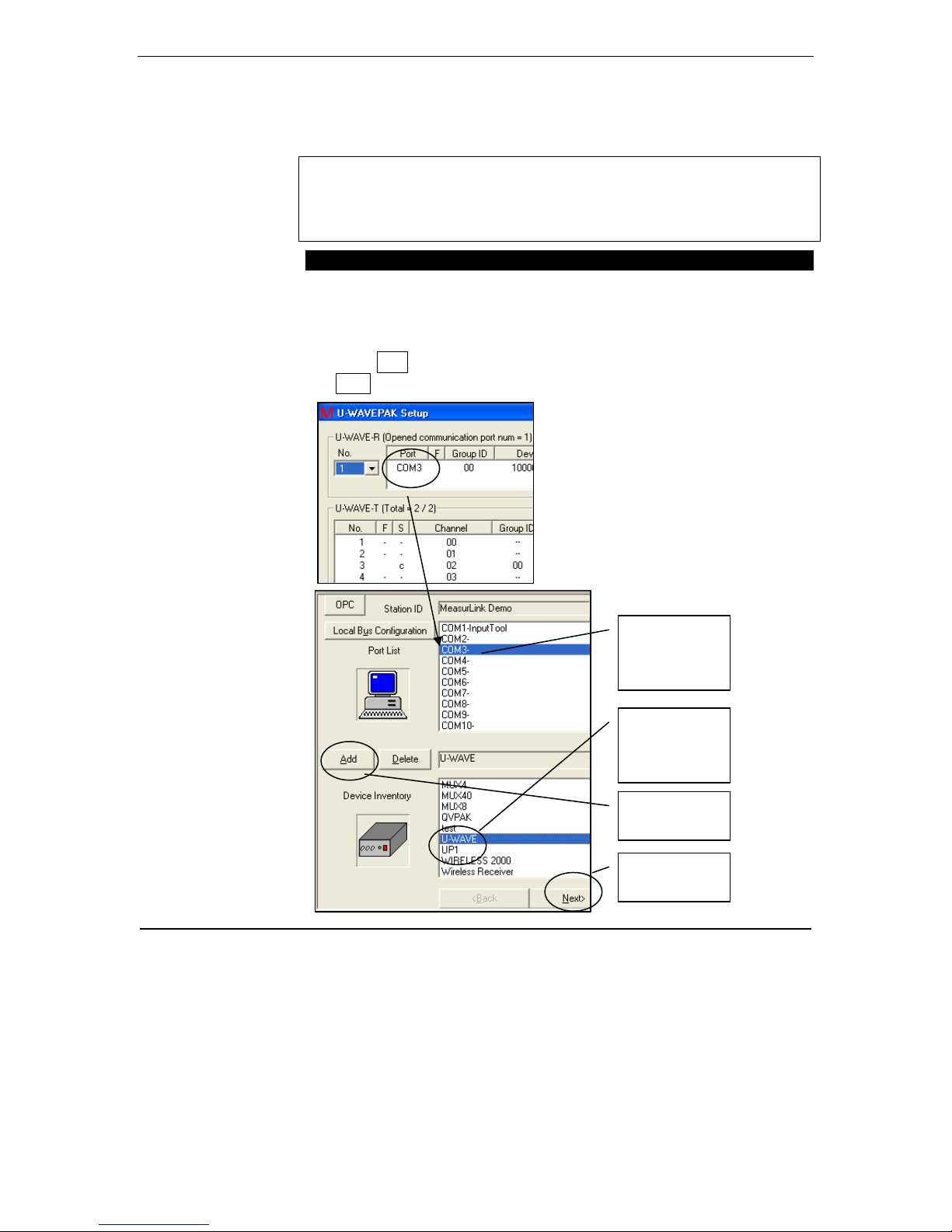
To Assign U-WAVE COM Port and Channels
1. Open Support Center, Workstation Center. Select the Com Port
created by U-WAVEPAK.
2. Select the U-WAVE device and Click add so the top box becomes
COM3 – U-WAVE in this example.
3. Click Add
4. Next
(MeasurLink)
8
MeasurLink
and U-WAVE
First,
Select the
COM Port
Second,
Select
U-WAVE
Third,
Click Add
Fourth,
Click Next
®

5. Select Channel that matches the channel number assigned to
C
lick Add
the gage in U-WAVEPAK.
6. Pick the gage that matches the gage sending the data. (Note:
MeasurLink will not restrict your use of any gage, but a good
reminder here prevents improper assignment of the channels in
the mapping step.)
7. Click Add
8. When all channels are assigned, click Exit.
Fifth,
Select Channel
(Note: Channel is
in Column 4 of
U-WAVEPAK)
Sixth,
Select Gage
Seventh,
User’s Guide
9

Variable Inspection Routine – Mapping
To Map U-WAVE Gage
The technique is the same as for any other direct gage input into
MeasurLink.
10
MeasurLink
and U-WAVE
®

System Requirements
Desktop PC / MeasurLink Client
Requirements for the MeasurLink Client can vary slightly depending on
the PDA NAVI system architecture used. Architecture diagrams are
provided in the Appendix section of this manual.
• MeasurLink Real-Time or Real-Time PLUS version 6.1 or higher.
• Microsoft Windows XP service pack 2 or higher
Support
Direct U.S. Support
Call 888 - Mitutoyo
User’s Guide
11

Installation
MeasurLink® Real-Time / Real-Time PLUS
MeasurLink Real-Time / Real-Time PLUS 6.1 should be installed on the
computer where you are adding the Mitutoyo U-WAVE wireless gage
multiplexer. If not, follow the instructions that come with the
MeasurLink Real-Time (PLUS) programs and perform a regular
installation. No special requirements are needed for the Mitutoyo UWAVE gage multiplexer.
If using an earlier version of the MeasurLink Real-Time (PLUS)
programs you must go to the MeasurLink Web site
www.measurlink.com
12
MeasurLink
Support > Down loads > register for the user ID and password > then
in the down loads section go to the Service Packs folder. Down load
(save) the MeasurLink 6.1.xx program, do not try and run it across the
internet. After the down load is finished, then run the update program at
the MeasurLink computer.
and U-WAVE
®

U-WAVE® Installation
U-WAVEPAK Installation on MeasurLink Real-Time
To Install U-WAVEPAK
1. Insert the U-WAVEPAK CD into the CD drive of the computer.
If Windows Explorer does not open to the CD disk, use Windows
Explorer to get to the C drive > Setup folder
User’s Guide
13

2. Double Click Setup.exe
3. Select English and click OK
4. Click on Next
14
MeasurLink
and U-WAVE
®
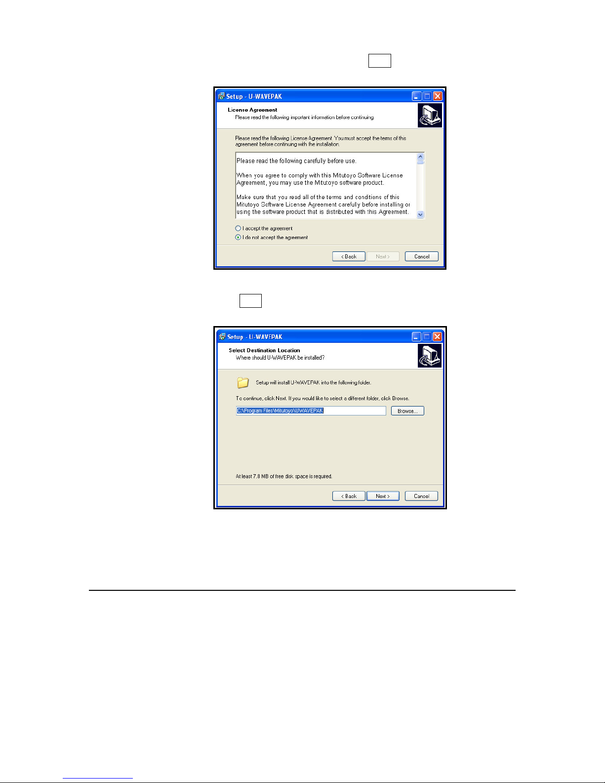
5. Read the License Agreement, and if you agree, select
I accept the agreement and select Next. (Otherwise cancel and
exit the setup.)
6. Click Next to accept the default location for the program installation
or Browse for another location.
User’s Guide
15

7. Select a name for the U-WAVE Start Menu Folder, Next
8. Add a check to create a U-WAVE icon on the desktop, Next
16
MeasurLink
and U-WAVE
®

9. Review the install parameters you selected and click Install.
10. Progress bar during the install.
User’s Guide
17

11. Click Finish. The installation of the software is complete.
12. Leave the CD in the CD drive.
U-WAVE Wireless Receiver
18
MeasurLink
To Install U-WAVE® Wireless Receiver
1. Plug the Wireless Receiver into a USB port on the computer.
2. Select No, not this time &click Next .
and U-WAVE
®
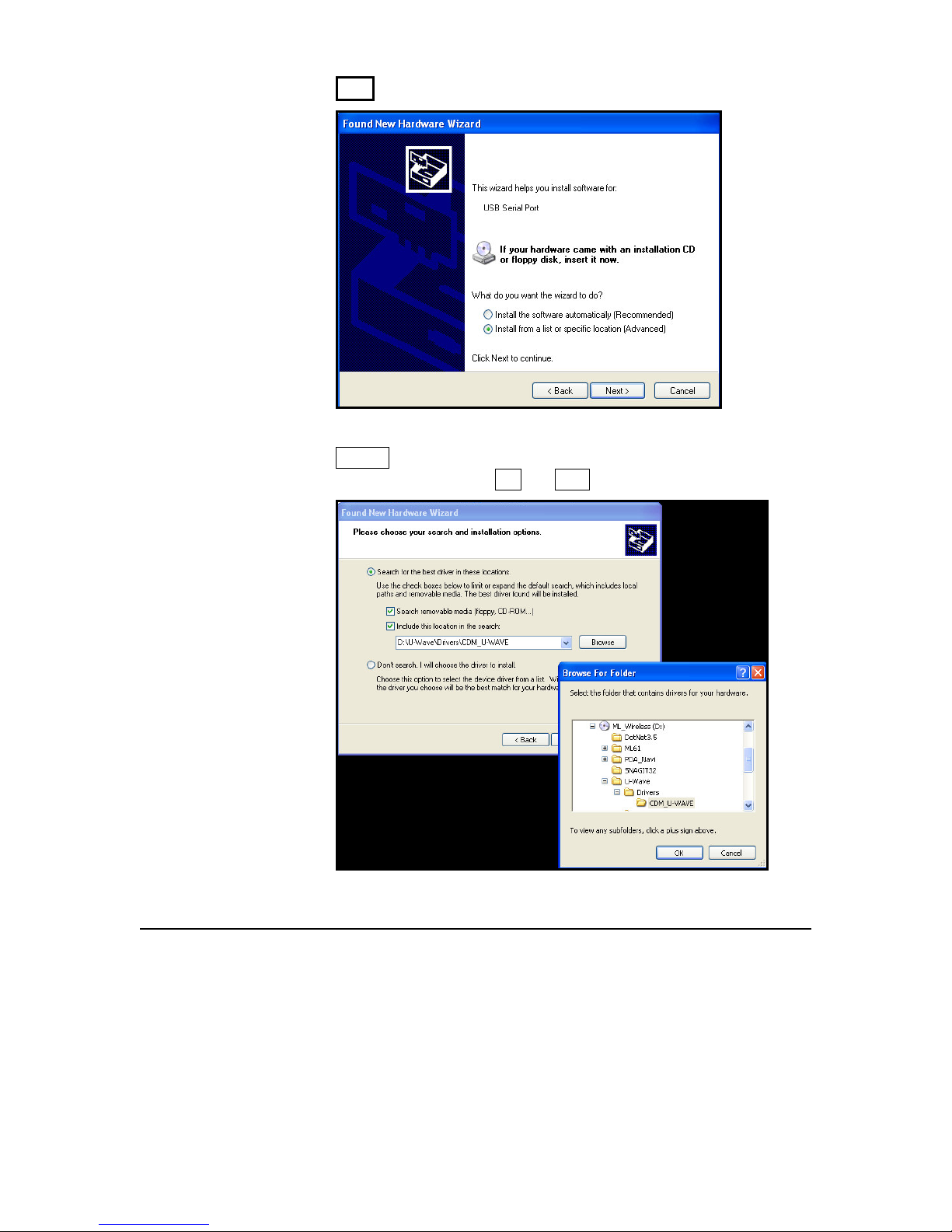
3. Select Install from a list or specific location (Advanced) & click
Next .
4. Browse out to the U-WAVE CD to the Drivers folder, select
COM_U-WAVE, then OK and Next.
User’s Guide
19
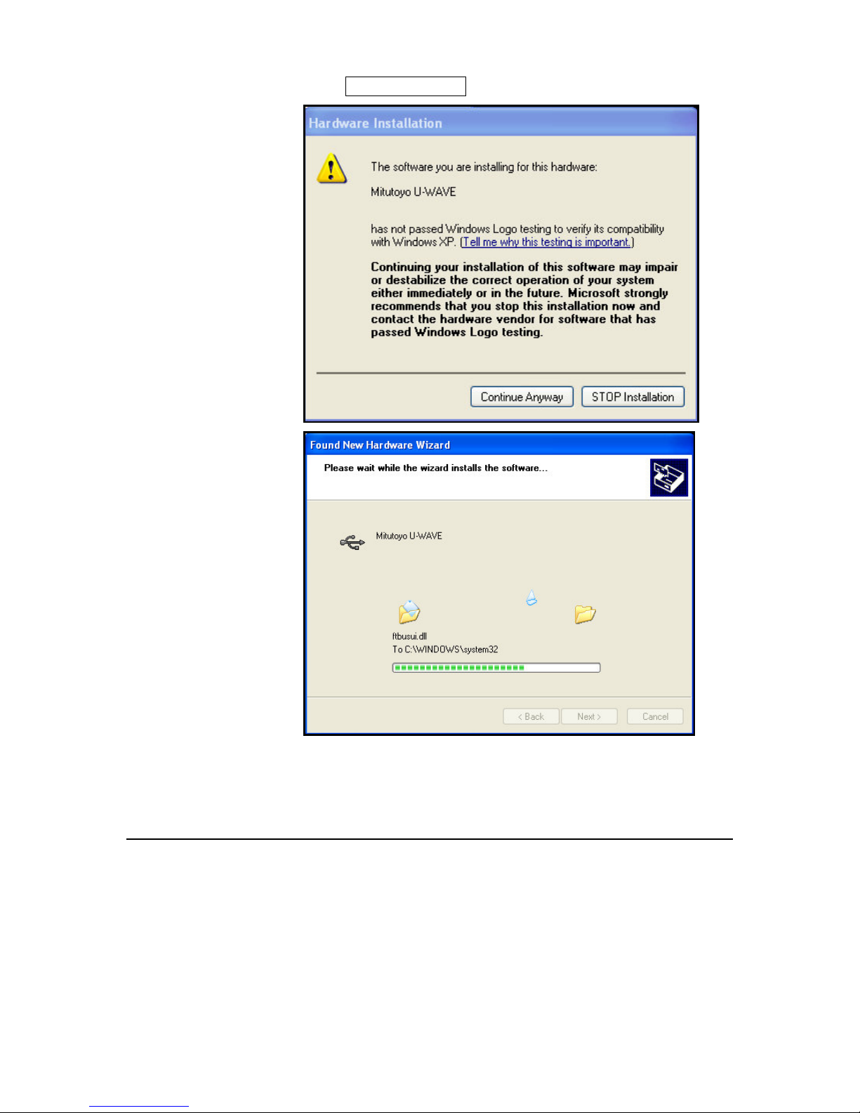
5. Select Continue Anyway.
20
MeasurLink
and U-WAVE
®

6. Driver software is being installed. Select
Finish.
7. NOTE: This New Hardware message will appear 3 times, once for
the U-WAVE device, once for the virtual com port software, and
once to create the U-WAVE com port assignment.
Only if New Hardware did not start automatically:
1. Click Start > Control Panel > Add Hardware and click
User’s Guide
Next
.
21

2. Select Search for and install the hardware automatically
(Recommended) and click
Next
. Otherwise refer to the U-WAVE
manual.
22
MeasurLink
and U-WAVE
®

U-WAVE® Organization
• Location of factory assigned IDs used in setup
• List of gages by Com port number and channel number used
by MeasurLink.
• U-WAVE-R wireless signals and gages sending data
User’s Guide
23

Setup for U-WAVE® with MeasurLink®
MeasurLink setup requires some additional steps after installing the UWAVE software and drivers.
U-WAVEPAK Setup
To Setup U-WAVEPAK
1. Start U-WAVEPAK program using the icon on the desktop if
requested (or use Start > All Programs > U-WAVEpak).
2. The first time this program is started, the following screen will be
displayed:
• Add check to Use the driver for Virtual Com Port
•
Leave
the check for When starting, this dialog is displayed
(later removal ok) & click
Add check to use the
driver
Leave check to display
at start (at least until
setup is complete)
OK.
24
MeasurLink
3. Click Setup Start.
Click Setup
Start
4. Complete the Virtual Com Port settings.
and U-WAVE
®

NOTE: Complete the Virtual Com Port settings in order shown below.
1. During the installation, Mitutoyo U-WAVE was assigned a com
port, select the Mitutoyo U-WAVE (COM_) line.
2. Set the Com port to match the one the installer selected.
3. Click the Add button – The com port parameters are always set
to Baud 57600, 0 (no parity), 8 data bits, 1 stop bit. To view the
wireless data using the Windows program Hyper Terminal, these
settings are required. MeasurLink 6.1 has a built-in device set
for these parameters.
4. Click OK.
This process will generally only be required once.
Fourth, Click
OK
Third, click
Add
Second, set
the com port
to match the
one from
below.
First, select
this line
User’s Guide
25

26
U-WAVE-R (Receiver) Setup
To Setup U-WAVE-R (Receiver)
1. If the U-WAVE-R box at the top of this dialog is empty, Click Edit
in the top right corner to add the U-WAVE-R device.
The factory assigned U-WAVE-R ID is the Device ID on the
U-WAVE-R setting information dialog.
MeasurLink
and U-WAVE
®
Click Edit to
add U-WAVER device
Factory assigned
U-WAVE-R
Device ID

2. The Device ID must match the ID on the U-WAVE-R device.
Accept all other default values and Click OK
Factory assigned
U-WAVE-R ID
(Shown in prior
picture)
DO
NOT
SELECT
INITIALIZE
BUTTON
User’s Guide
27
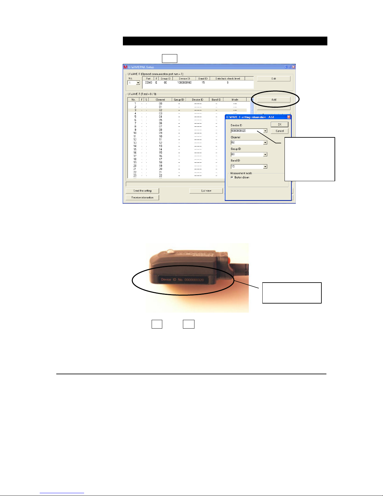
U-WAVE –T (Transmitter) Setup
To Setup U-WAVE-T (Transmitter)
1. Click the ADD button near the top right.
2. In the U-WAVE-T setting Information – Add dialog, type in the
Device ID found on the U-WAVE-T device. Change the Channel
number as needed, but leave all other defaults.
Factory assigned
U-WAVE-T ID
3. Click OK &then Yes to confirm processing.
Factory
assigned
U-WAVE-T
Device ID
(shown below)
28
MeasurLink
and U-WAVE
®

r = registered, but
not connected
Instructions to
connect the gage with
U-WAVE-T device
4. The r = registered with the U-WAVE-T device, but the gage is
not connected for transmitting data.
User’s Guide
29

c shows the
gage is now
connected
Value sent by
the gage
5. Connect a gage and turn on. Push the data button on the U-
WAVE-T (transmitter). There should be two beeps heard and a
green light visible two times. Check column S for the “r” (for
registered) to change to “c” for connected.
6. Only if the gage did not connect as expected, perform a scan.
Press and hold for 10 seconds the data button on the
U-WAVE-T. There should be a fast flashing red light followed
by a slower flashing red light. Check column S for “c” for
connected to be displayed.
7. If there are problems, see the U-WAVE manual about resetting
both the U-WAVE-R and the U-WAVE-T devices.
30
MeasurLink
8. Add additional gages as needed. When using two or more
U-WAVE-R devices (Receivers) on the same computer, the
Group ID is used to automatically connect the U-WAVE-T,
wireless transmitters with the U-WAVE-R.
and U-WAVE
®

Write down on
paper the Com
port assigned to
U-WAVE –R
Write down on
paper the channel
number assigned
to
U-WAVE-T
NOTE:
CHANNEL
COLUMN!
9. IMPORTANT: Write down the Com Port assigned to the UWAVE-R device and the channel number (in the 4th column)
assigned to the U-WAVE-T device. These will be used during
MeasurLink Setup.
10. Once all the gages have been assigned, exit from the setup and
exit from the U-WAVEPak program.
IMPORTANT: Exit is required from both setup and
U-WAVEPack to allow MeasurLink to capture data directly
from the wireless devices.
User’s Guide
31
 Loading...