

Page 1
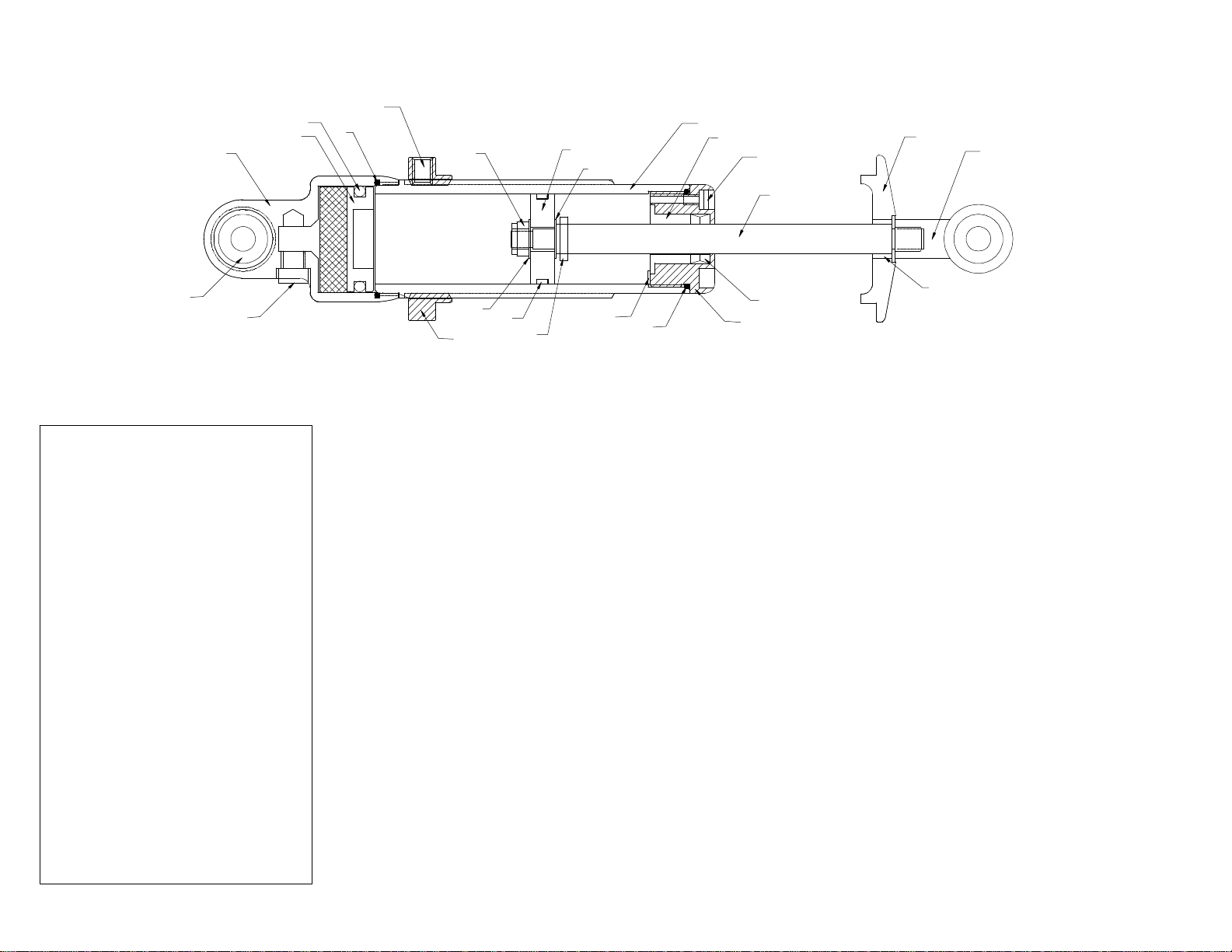
G-3 SHOCK ASSEMBLY
J
U
X
M
E
V
K
W
B
O
L
H
F
A
I
N
INDEX
A= 8551-110 Rod End
B= 8551-010 ShockBody
C= 8551-030 Shaft Guide (BARE)
D= 8551-060Adjustment Nut
E= 8551-020 SeperatorCap(Bare)
F= 8551-040 Spring Cone
G= 8551-050Cone Spacer
H= 8551-070 Shaft
I= 8551-120 SphericalBearing
J= 8551-200 #10 Set Screw
K= 8551-080 Control Piston
L= 8551-170 Bleed Screw
M= 8551-090Seperator Piston
N= 8551-290 Gas Port Plug
O= 8551-150BronzeBushing
P= 8551-140 U-Cup(2)
Q= 8551-160Bushing Retainer Screw
R= 8551-230 Shaft Guide O-Ring
S= 8551-220 Control PistonBand
T= 8551-270 Internal Bumper O-Ring
U= 8551-280 Seperator PistonO-Ring
V= 8551-260 1/4-28NylockNut
W= 8551-250 1/4" Washer (2)
X= 8551-240 SeperatorcapO-ring
W
S
D
T
Q
R
P
C
G
SHOCK REBUILDING
1. Clamp shock into vice using shock jaws (Part # 75570) with the rod end facing upward.
2. Remove the bleeder screw from the shaft guide.
3. Remove the shaft guide, rod and piston assembly from the shock body using the shock wrench (Part # 75575).
4. Remove the shock body from the vice and clamp the shaft assembly in the vice.
5. Remove the 1/4-28 nut from the shaft and pull off the piston, washers and shaft guide assembly.
6. Remove the bushing retainer screw, and using the end of the shaft (or something similar) push the bronze
bushing out from the bottom side of the shaft guide.
7. Remove the old u-cup seals and clean out the shaft guide using cleaner such as brake cleaner or solvent.
8. Insert new u-cup seals facing the proper direction (see drawing above).
9. Clean and reinstall existing bronze bushing (this very rarely wears out) and bushing retainer screw .
10. Change the o-ring on the outside of the shaft guide and reassemble shaft guide , piston, washers and nut back
onto the shaft.
11. Dispose of all remaining shock oil left in the shock body and clean the body internally to remove any contaminants.
12. Grip the shock body in the vice with the separator cap assembly facing upwards using shock body jaws (Part # 75572).
13. Using the slot in the shock wrench, remove the separator cap assembly (this part is loctited on so it may be difficulttoremove).
14. Push down the seperator piston and remove the internal o-ring (X) then remove the seperator piston.
Do not remove the black closed cell bladder under the seperator piston.
15. Change the o-ring on the separator piston and reassemble separator piston into the separator cap pushing it down enough to
install the new o-ring (x).
16. Clean all of the old loctite off of the threads of the shock body.
17. Put new loctite on the threads of the shock body and reinstall the separator cap assembly making sure not to get any loctite on
the inner surfaces of the shock.
18. Allow the loctite to dry for a minimum of 15 minutes, then turn the shock back over in the vice and grip with the shock jaws.
19. Fill the shock with oil to the bottom of the internal threads.
20. Place the drip cup onto the shock (part # 75566).
21. With the shaft fully extended out of the shaft guide, reinstall the shaft and shaft guide assembly making sure the shaft stays fully extended.
22. Tighten the shaft guide assembly with the shock wrench.
23. Reinstall the bleed screw.
24. Depress and extend the shaft several times and you will hear the air bubbles go away. Your shock is now ready to race.
 Loading...