

Page 1
(636) 745-7757
Fax: (636) 745-2874
Division of Mittler Corp.
P.O. Box 110 Foristell, Missouri 63348
10 Cooperative Way Wright City, MO 63390
400 Single Speed to Variable Speed Conversion
#400-202
1. Unpack the boxes and be sure all the parts are included. See the list at the end of these
instructions.
2. Unplug the machine from any power source. Remove the switch box from the base plate by
removing the cover and unscrewing from the base plate.
3. Remove the Love Joy Cover by removing the two screws. Then loosen the set screws on each
half of the Love Joy coupling.
4. With someone holding up the end of the motor remove the four (4) bolts holding the motor /
gearbox assembly to the mounting plate. Remove the complete motor, gearbox, cord & switch
assembly from the machine. Save the mounting bolts to remount the motor / gearbox.
5. Remove the Love Joy coupling half from the spindle shaft if it did not slide off in step 4.
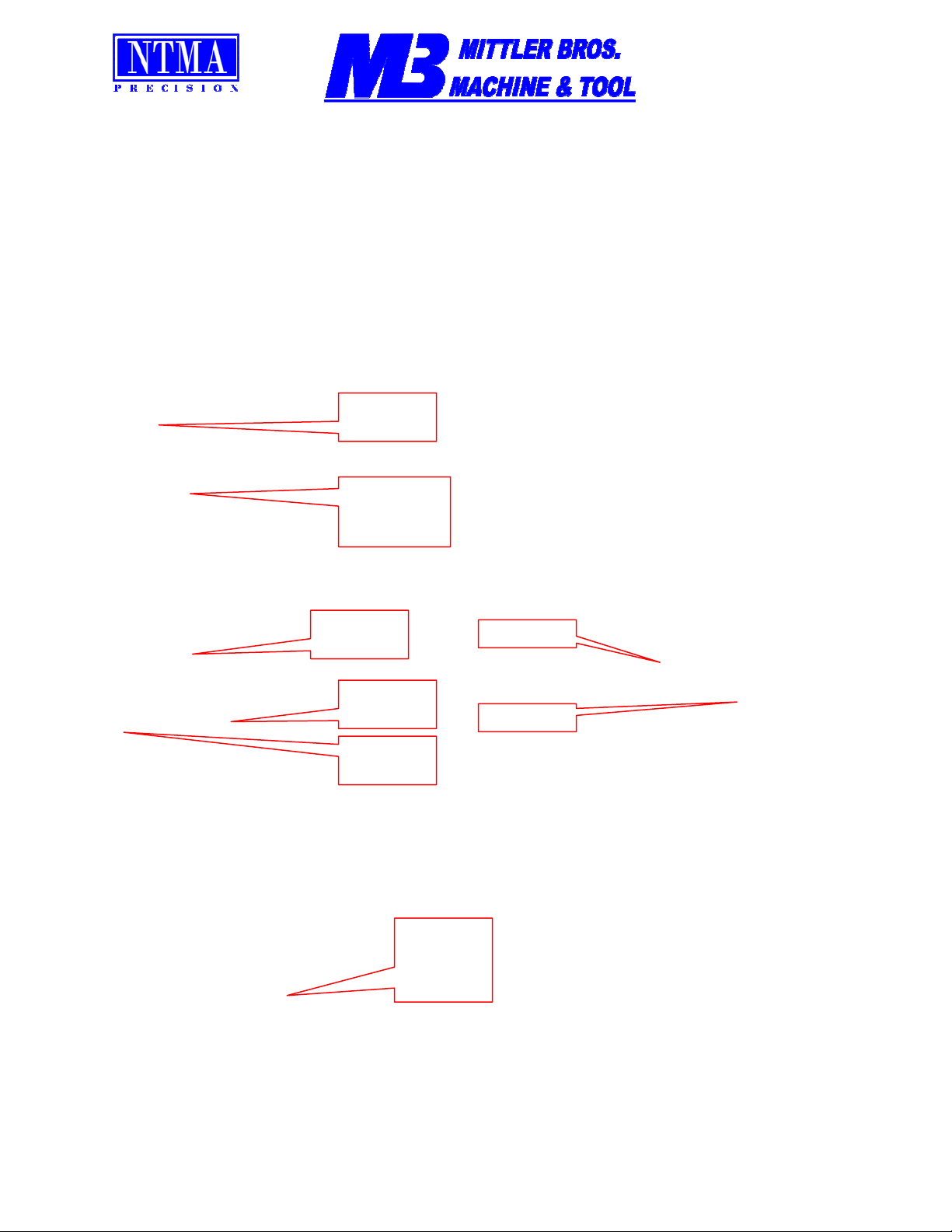
Remove
Cover
Unscrew
from Base
Plate
Love Joy
Cover
Remove
Screw
Remove
Screw
Set Screw
Set Screw
Mounting
Bolts. 2
on Each
Side
\\Mbserver01\engineering\Product\Product Documentation\400 Ultimate\VS Conversion Instructions.doc Rev1 12-16-2005
Page 2
6. Drill and tap two (2) holes, 5/16”-18, in the motor mounting plate as shown below. The holes
should be drilled 1” deep and then counter sunk a small amount to allow for the bolt heads.
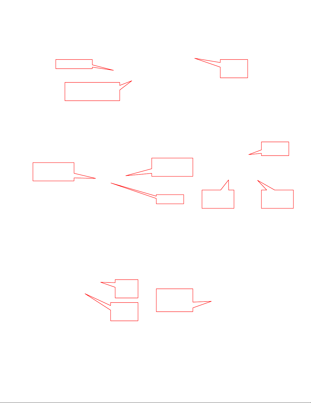
Motor Side
Spindle
Side
Drill & Tap 1” deep
for 5/16”-18
7. Slide the large bore (1”) Love Joy coupler half onto the spindle. Be sure the “fingers” are pointing
toward the motor location and that the key is installed in the key way. Do not tighten down set
screw at this time.
Spider
Gearbox Side
Small Bore
Spindle Side
Large Bore
Fingers
Small
3/4” Bore
Large
1” Bore
8. Assemble the motor to the gear box. Use supplied anti-seize from the gear box container and
lube the inside of the gearbox shaft where the motor slips in. Be sure the motor to gearbox
mounting flange on the gearbox has no bolts in it. Be sure the supplied key is in the motor shaft
and slide the motor and gearbox together. Make sure the motor is rotated so that the wire
connection box is on the side as shown. Install the four (4) bolts and lock washers by hand and
then tighten once you are sure that everything is lined up.
Gear
Box
Lube
Inside
Wire
Connection
Box
9. Slide the small bore (3/4”) Love Joy coupler half onto the gearbox shaft. Be sure the “fingers” are
pointing away from the gearbox and that the key is installed in the key way. Do not tighten down
set screw at this time. Slip the “spider” into the fingers of the coupler.
Page 3

10. Set the motor / gearbox assembly onto the mounting plate. While someone is holding the motor
end up install the mounting bolts finger tight. Use mounting holes farthest from the spindle as
shown below.
New
Mounting
Holes
Spindle
(Love Joy coupler removed)
Old
Mounting
Holes
11. Slip the two Love Joy coupler halves together with your fingers, being sure the spider is still
locked in the “fingers”. Tighten the set screws and snug up the motor / gearbox mounting bolts.
Set Screw
Set Screw
12. Install the new Love Joy cover using the old screws.
13. Bolt the control box mounting plate to the motor / gearbox mounting plate using the holes you
drilled earlier and the 5/16”-18 x ¾” FHCS.Put a drop of locktite on the bolt threads. Be sure the
long end of the plate is at the top.
Long End
Top
14. Mount the Speed Control box to the mounting plate using the supplied 1/4”-20 x ½” SHCS. This
step will require a long allen wrench to reach inside the control box.
Access
Mounting bolts
through slots
at 4 Places
Page 4

15. Attach the conduit elbow to the bottom of box by removing the nut, slipping the fitting through and
then installing and tightening the nut.
Conduit Nut
Conduit Elbow
Elbow Goes Here
16. Wire the control box to the motor as shown by the included wiring diagram. Use the supplied wire
nuts and then use electrical tape for added safety.
17. Wire the input cord correctly for the style and voltage you are using, refer to enclosed wiring
diagram.
18. Check all bolts for tightness and all electrical connections. Once you are sure everything is tight
and correct set the master switch to OFF and the run switch to STOP. Plug the power cord into
the receptacle.
Speed
Control
Knob
Run Switch
STOP
Master Switch
OFF
19. Turn the MASTER switch on and then turn the RUN switch on. Turn the speed control knob up
and down to cycle the motor. Listen for and clicking or odd sounds. If you here a clicking sound
you will need to loosen the spindle housing bolts and then retighten while the motor is running.
This will usually align the Love Joy and quiet the clicking.
KIT CONTENTS:
1ea. 400-503-M Motor
1ea. 400-503-G Gear Box
1ea. 400-035 Large Love Joy Coupling Cover (guard)
1ea. 400-507 Love Joy Coupler Half 3/4” ID
1ea. 400-508 Love Joy Coupler Half 1” ID
1ea. 400-509 Love Joy Coupler Spider
1ea. 400-039 Control Box Mounting Plate
1ea. Pre Wired Speed Control Box
2ea. 5/16”-18 x 3/4” FHCS
4ea. 1/4”-20 x 1/2” SHCS
1ea. Wire Diagram
1ea. Instruction Sheet Set
We appreciate your business and hope that you enjoy your new Mittler Bros. Product. If you have any
questions or concerns please feel free to call us at 1-800-467-2464 for help.
Page 5

 Loading...