

Page 1

Division of Mittler Corp.
P.O. Box 110 Foristell, Missouri 63348
10 Cooperative Way Wright City, MO 63390
3100-100 Universal Tool Stand
Assembly Instructions
Kit Includes:
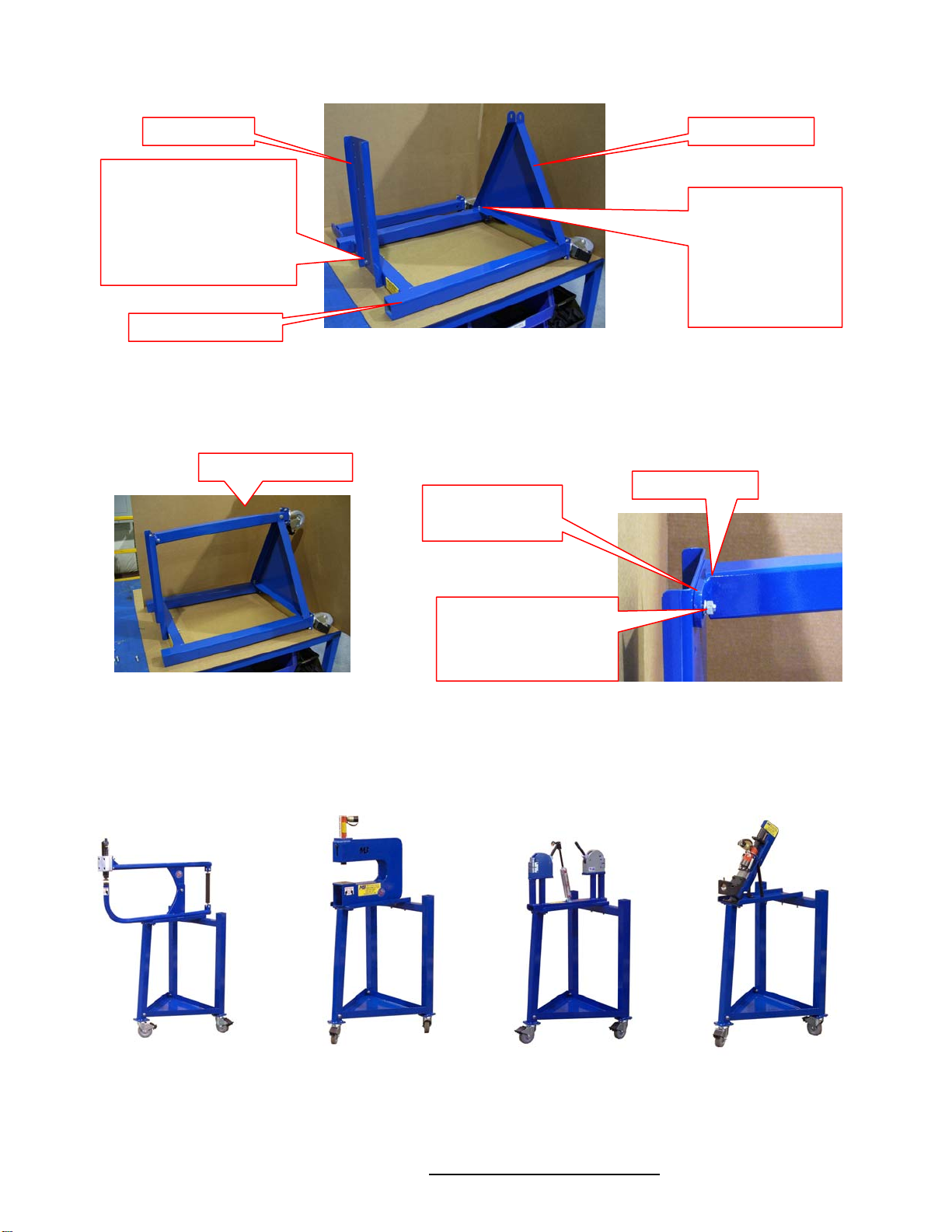
1 ea. Rear “H” frame
1 ea. Front Leg
1 ea. Top Tray
1 ea. Bottom Tray
18 ea. 5/16-18 x 1” Bolts
2 ea. 5/16” -18 x3” Bolts
20 ea. 5/16” Lock washers
1. Un-package the contents and verify that nothing is damaged or missing.
20 ea. 5/16” Nuts
16 ea. 5/16” Flat Washer
3 ea. Swivel Casters, Locking
3 ea. 3/8-16 x 3” Bolts
3 ea. 3/8” Nuts
3 ea. 3/8” Lock washers
6 ea. 3/8” Flat washers
1ea. Instruction Sheet
(636) 745-7757
Fax: (636) 745-2874
Check
Hardware
Bottom
Tray
3ea
Swivel
Casters
Rear “H” Frame
Top Tray
Front Leg
Lay the “H” Frame down like shown below. Attach the casters using the 5/16” x 1” bolts, lock washers & nuts. Bolt the
2.
remaining caster to the bottom of the front leg as shown. Be sure bolt are installed from the caster side.
Rear “H” Frame
Front Leg
3ea
Swivel
Casters
\\Mbserver01\Engineering\Product\Product Documentation\3100 Universal Tool Stand\Universal Stand Assm. Instructions.doc Rev1 417-2007
Use 5/16” x 1”
bolts, lock
washers & nuts.
Bolt Heads Must
be on Caster
Side
Page 2
y
3. Attach the bottom tray to the rear H frame using the 3/8” x 3” bolts, lock washers & nuts. Attach the top tray to “H”
frame using the 5/16” x 3” bolts, lock washers & nuts.
Top Tray
Use 5/16” x 3” Bolts,
Lock Washers & Nuts.
Put Flat Washers
Under Bolt Head &
Under Lock Washer &
Nut on Frame Side.
Rear “H” Frame
Bottom Tra
Use 3/8” x 3”
Bolts, Lock
Washers & Nuts.
Put a Flat
Washer, Lock
Washer & Nut on
Tray Side.
4. Install the Front Leg by slipping it between the the tabs on the bottom tray and inserting a 3/8” x 3” bolt through the
holes. Be sure that the mounting plate at the top is angled correctly as shown below. Use 5/16” x 1” bolts, lock
washers & nuts to attach the leg top plate to the Top Tray. Put the flat washers on the tray side & nuts on the frame
side.
Fully Assembled
5/16” x 1” Bolts
Lock Washers
Note Angle
Be Sure the Leg Top
Plate Is Installed so
the Leg is Angled
Forward.
5. Pre Drilled mounting holes allow a multitude of MB machines to be mounted without any drilling. Addtional machines
of yours may be mounted by drilling your own mounting holes. BE SURE STAND IS STABLE WHEN MACHINES
ARE MOUNTED. MACHINE DAMAGE AND / OR PERSONAL INJURY MAY OCCU R IF M ACHINES ARE
IMPROPERLLY MOUNTED. ALWAYS LOCK CASTER WHEN IN USE!
Thank You for Your Purchase.
We appreciate your business.
If have any questions, comments or suggestions please contact us.
1-800-467-2464 www.mittlerbros.com
 Loading...