

Page 1
- 1 -
Operating, Servicing, and Safety
Manual
Model # 2500
180° Hydraulic Bender
CAUTION: Read and Understand
These Operating, Servicing, and
Safety Instructions, Before Using
This Machine.
1-800-467-2464
10 Cooperative Way Wright City, MO 63390
P.O. Box 110 Foristell, MO 63348
1-636-745-7757 Fax 1-636-745-2874
www.mittlerbros.com
Page 2

- 2 -
Table of Contents
• Safety Pg.3
• Hydraulic Safety Precautions Pg.4
• Prep/ Set Up P g.4
• Bender Contents Pg.5
• Uncra te and Set Up Pg.6
• Hydraulic System Pg.7
• Getting Ready To Bend Pg.8-9
• Digital Readout Operation Pg.9
• Tubing Spring Back Pg.9
• Mathematics For Hyd. Tube Bender Pg.10-13
• Technical Diagram Pg.14-22
• Maintenance Pg.23-24
• Optional Equipment Pg. 25-28
Page 3

- 3 -
SAFETY
The purpose of the safety section of this manual is to inform operators and maintenance
personnel of the precautions to be taken while operating or servicing the machine. The following are
a few basic guidelines to follow, but as with any type of machinery good judgment and a safe
attitude should be applied at all times.
1 Always disconnect power, lock-out and tag-out machine per OSHA regulations before attempting to
service this machine.
2. Always wear safety glasses or other approved eye protection while operating or servicing the machine.
3. Keep all body parts and any foreign objects away from moving parts. Do not reach into the machine
without first disconnecting all power sources.
4. Do not attempt to override any safety device on the machine.
5. Do not operate the machine if it has been damaged or is not operating properly.
6. Do not wear jewelry (watches, rings, necklaces, etc.), or loose fitting clothing while operating or
servicing the machine.
7. The machine should only be operated or serviced by properly trained, authorized personnel.
8. Replacement parts should have the same specification and operation as the original parts on the
machine.
9. All guards and covers must be in place before operating the machine.
10. Before starting the machine be sure it is set up properly.
11. Make sure the machine is properly grounded.
12. The machine and work area should be kept neat and clean.
13. Do not operate or service any machine while under the influence of drugs or alcohol.
NOTE: THESE SAFETY RULES ARE FOR YOUR BENEFIT TO HELP PREVEN T I NJURY TO YOURSELF AND/OR
YOUR CO-WORKERS. REVIEW ALL SETUP AND OPER ATING P ROCEDURES, WHETHER COVERED OR NOT,
IN THIS MANUAL TO HELP INSURE SAFE OPERATION OF THE MACHINE.
Page 4

- 4 -
HYDRAULIC SAFETY PRECAUTIO NS
WARNING
General Operation
• All WARNING statements must be carefully observed to help prevent personal injury.
• Before operating the pump, all hose connections must be tightened with the proper tools. Do not over
tighten. Connections should only be tightened securely and leak-free. Over tightening can cause
premature thread failure or high pressure fittings to split at pressures lower than their rated capacities.
• Should a hydraulic hose ever rupture, burst, or need to be disconnected, immediately shut off the
pump and release all pressure. Never attempt to grasp a leaking pressurized hose with your hands.
The force of escaping hydraulic fluid could cause serious injury.
• Do not subject the hose to potential hazard such as fire, sharp surfaces, extreme heat or cold or
heavy impact. Do not allow the hose to be altered or kink, twist, curl, crush, cut, or bend so tightly that
the fluid flow within the hose is blocked or reduced. Periodically inspect the hose for wear, because
any of these condition’s can damage the hose and possibly result in personal injury.
• Do not use the hose to move attached equipment. Stress can damage hose and possibly cause
personal injury.
• Hose material and coupler seals must be compatible with the hydraulic fluid used. Hoses also must
not come in contact with corrosive materials such as creosote-impregnated objects and some paints.
Consult the manufacturer before painting a hose. Hose deterioration due to corrosive materials can
result in personal injury. Never paint the couplers.
• Inspect machine for wear, damage, and correct functio n be fore each use. Do not use machinery that
is not in proper working order, but repair or replace it as necessary.
• Replace worn or damaged safety decals.
• Modification of a product requires written Power Team authorization.
• Use only components with the same pressure rating when assembling a system or machine.
Pump
• Do not exceed the hydraulic pressure rating noted on the pump data plate or tamper with the internal
high pressure relief valve. Creating pressure beyond the rated pressure can result in personal injury.
• Before replenishing the fluid level, retract the system to prevent overfilling the pump reservoir. An
overfill can cause personal injury due to excess reservoir pressure create when cylinders are
retracted.
Air Supply
• Shut off and disconnect the air supply when the pump is not in use or before breaking any
connections in the system.
PREPARATION & SET-UP
Air Supply Hook-Up
Remove the thread protector from the air inlet of the pump. Select and install the threaded fittings which are
compatible with your air supply fittings. The air supply should be 20 CFM (.57 M3/min.) and 100 PSI (7 BAR)
at the pump to obtain the rated hydraulic pressure. Air pressure should be regulated to a maximum of 140
PSI (9 BAR). Secure your pump fitting to the air supply.
WARNING: If improperly used, pressurized equipment can be potentially hazardous. Therefore:
• Hydraulic connectio ns must be securely fastened before building pressure in the system.
• Release all system pressure before loosening any hydraulic connection in the system.
Venting the Reservoir
To improve hydraulic fluid delivery and increase useable hydraulic fluid capacity, remove shipping plug and
install filler/vent cap before using the pump.
Page 5

- 5 -
#2500 BENDER CONTENTS
• 1ea Main bender assembly mounted to stand
• 1ea Swivel work table
• 1ea Rectangle shaped shelf
• 1ea Angle shaped shelf
• 2ea Rigid casters
• 2ea Swivel Casters , Locking
• 16ea 5/16-18 x 3/4 Hex Bolt (for mounting casters)
• 16ea 5/16-18 Hex Nut (for mounting casters)
• 16ea 5/16 Lock washer ( for mounting casters )
• 16ea 5/16 Flat wash er (for mounting caster s )
• 5ea “U” spacers for pressure roller shaft, 1” thick
• 1ea #2500-300 Small adj us table Saddle
• 1ea #2500-301 Medium adjustable Saddle
• 1ea Operating, Ser vicing, and Safety Manual
Page 6
- 6 -
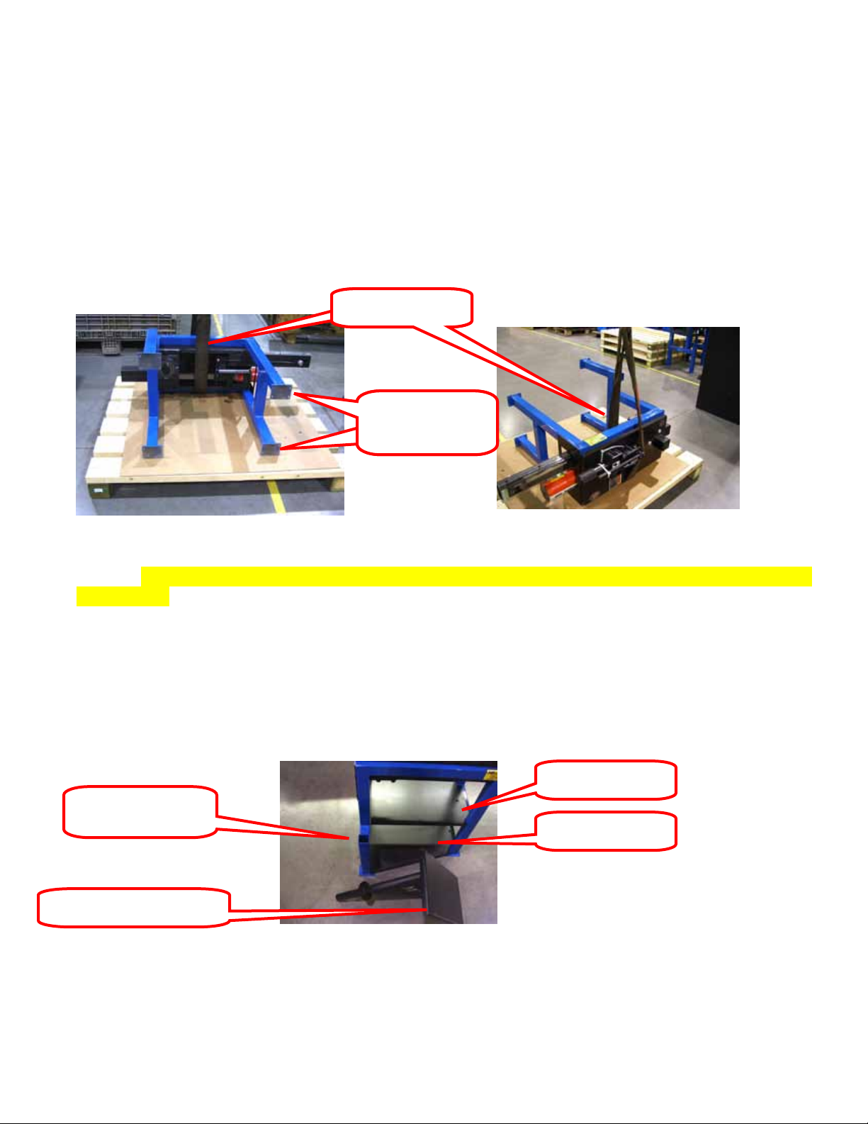
#2 Swivel
End
#2 Swivel
End
#3 Sling Position #3 Sling Position
#4 Upper Shelf
#4 Lower Shelf
#5 Swivel Work table
#5 Swivel Work
UNCRATE & SETUP
1. Remove shrink wrap and upper crating structure. Remove the two black shelves and work table from
the skid. Locate the box that contains the casters.
2. Attach the casters to the mounting plates using the supplied hardware. The swivel casters should be
mounted on the same end of the machine as the hydraulic cylinder and digital readout.
Casters This
Casters This
3. Once the casters are installed, use a sling positioned as shown above, to lift the machine onto the
casters. CAUTION: MACHINE IS HEAVY AND MAY CAUSE DAMAGE OR INJURY IF CARE IS
NOT USED.
4. Install the bottom shelf (with angled side) onto the bottom of the frame. It will rest on the caster
mounting plates. The bent sides point up. Install the upper shelf (rectangle shaped) next. This one
also should have the bent sides pointing up. You will have to tilt the shelves to fit in between the legs
and then lay them flat.
.
table goes in here
5. Slip the swivel work table into the open end of the square tube leg
Page 7
- 7 -
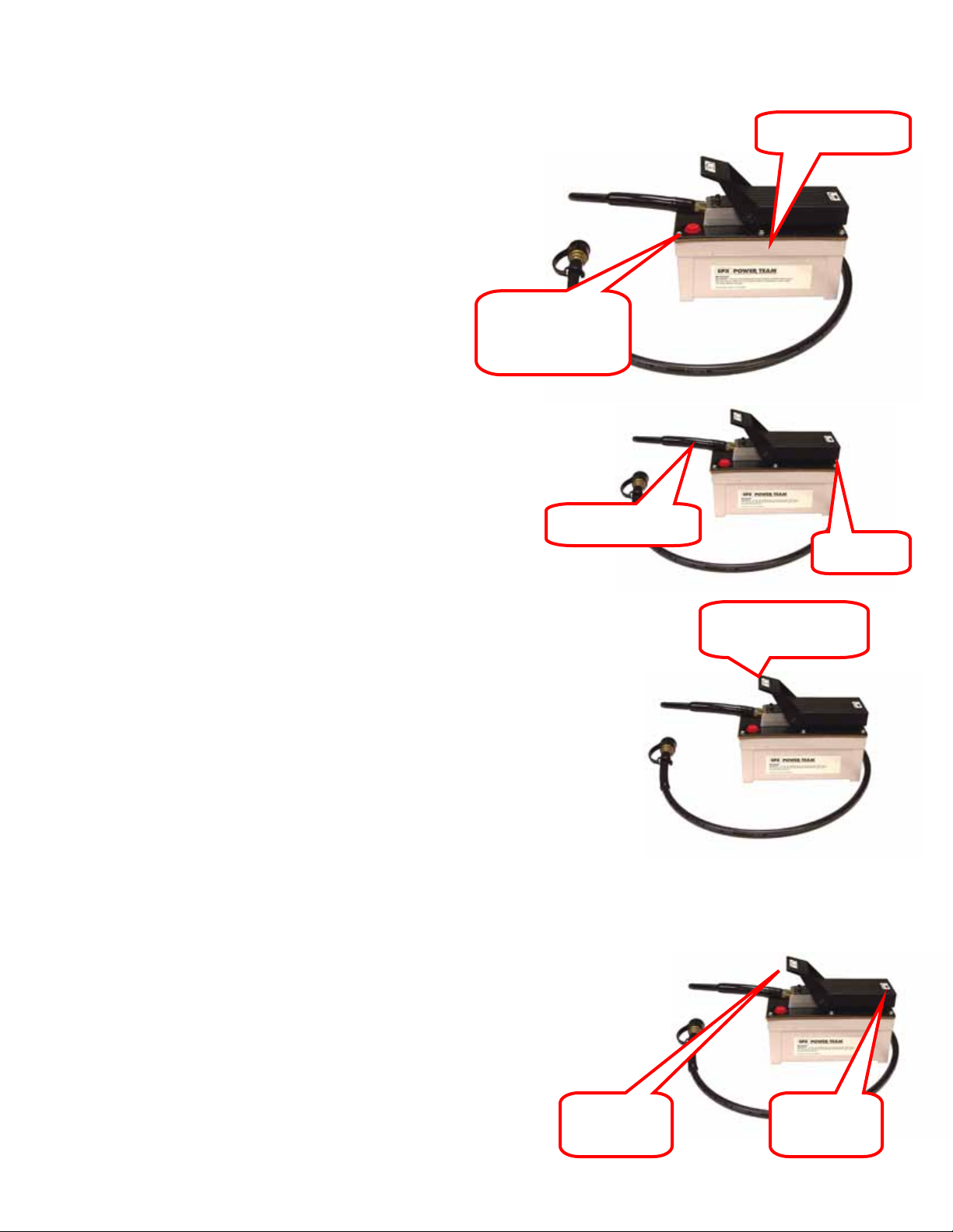
RED Plug should
Pump Assembly
Hydraulic Hose
Air Hose
Push Down to
HYDRAULIC SYSTEM
1. Remove the RED Plug in the pump assembly and
replace with the supplied BLACK plug. This is
the reservoir venting system and damage or
inoperability may result if not changed out.
2. Attach the hydraulic hose to the pump. Attach an air line
fitting for your shop air to other end of the pump. Be sure
to use a quality thread sealer on both connections
3. Push the pump foot pedal to the release position (TOE END)
to relieve all internal pressure. Push the MALE hose end,
from the pump, into the FEMALE Cylinder fitting & then
thread the retainer collar hand tight. This procedure will insure
that the male & female fittings positively seat against each
other, eliminating any poss i bil i ty of air locking. Failing to
follow this procedure may cause the cylinder to not retract
and / or leak.
4. BLEED THE CYLINDER; Connect a compressed air supply
(90PSI) to the pump. Elevate the pump and hose above the
cylinder. Push the hydraulic pump pedal HEEL END to actuate
the cylinder. Run the cylinder out about half way. Release the
pump by pressing on the TOE END of the pedal. Repeat this
process three or four times or until the ram cylinder movement is
smooth.
be changed to
BLACK Plug
Release Pressure
TOE END
Retract
HEEL END
Pump
Page 8
- 8 -
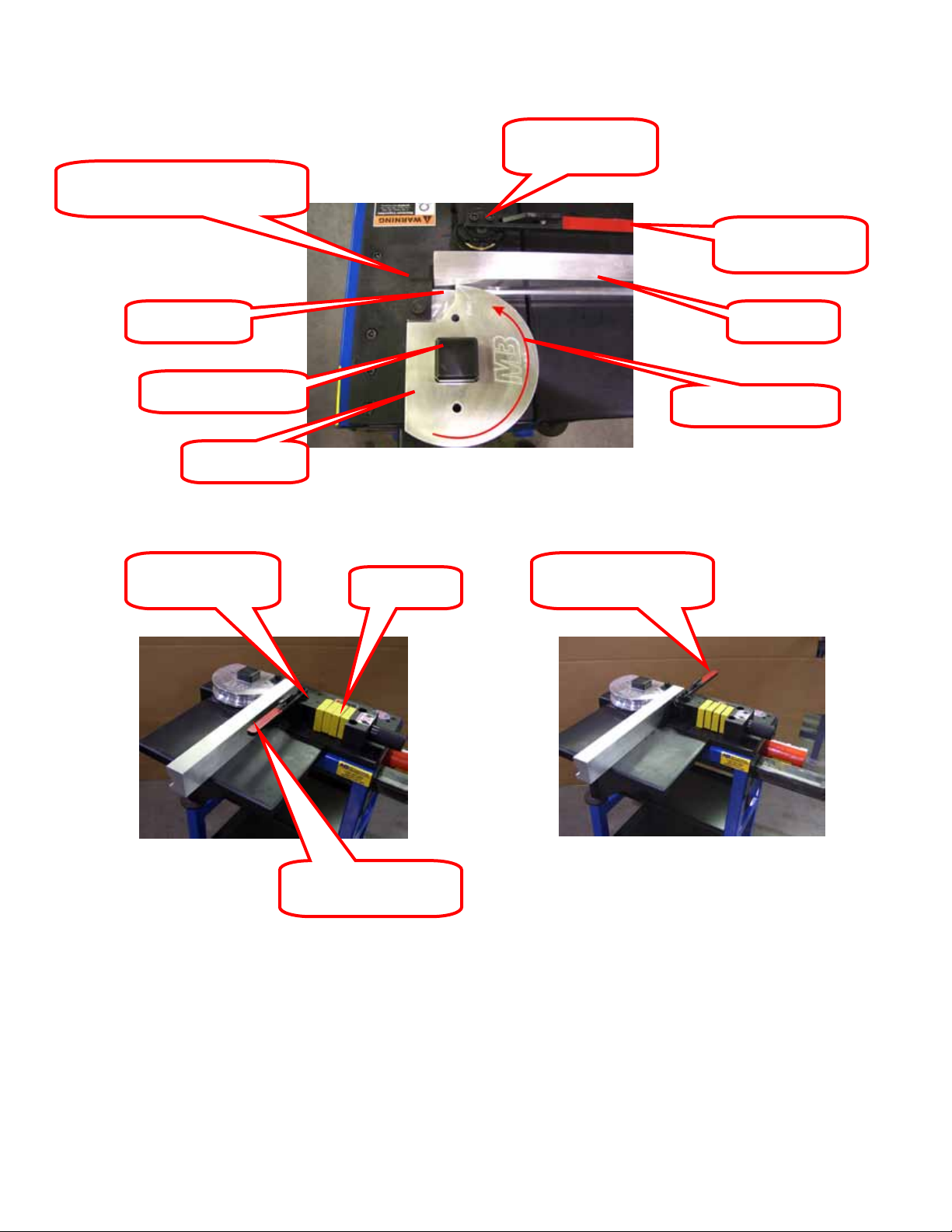
U Saddle & Pin Assembly or
Pressure Roller
Pressure Roller
Pressure Roller in
Pressure Roller
Pressure Roller in
Adjustable Saddle Assembly
Start Mark
Square Drive Shaft
Bender Shoe
Assembly
GETTING READY TO BEND
Assembly
Rotation Direction
“U” Shims
Bend Position
Released Position
Release Handle
Follow Bar
1. Slide the main Bender Shoe over the Square Drive Shaft. Be sure that the MB and
START are facing up and that they are positioned as shown above. The START
engraving should be closest to the P r es su re R ol ler Assembly.
2. Position the Pressure Roller Assembly to the correct position by adding or subtracting
“U” shims until the follow bar is almost touching the bender shoe, Be Sure the Pressure
Release Handle Is in the Bend Position as Shown.
Page 9

- 9 -
ON / Zero
Inch / MM
3. Move the Pressure Release Handle to the RELEASED position and place the tubing
(which has already been marked with the bend start points) into the Bender Shoe with
the first bend start mark aligned with the START arrow on the Bender Shoe. Slip the
“U” Saddle or Adjustable Saddle over the tubing and the Bender Shoe. Align the
holes and install the pin, if using the adjustable saddle, tig hten down the clamp knob.
CAUTION: THE PIN MUST BE COMPLETELY THROUGH BOTH SIDES OF THE “U”
SADDLE! FAILURE TO HAVE PIN COMPLETELY INSTALLED MAY RESULT IN
EQUIPMENT DAMAGE AND / OR PERSONEL INJURY!
4. Align the front edge of the Follow Bar with the START arrow on the Bender Shoe. Be
sure the start mark on the tubing is still lined up with the START arrow as well. Run the
Pressure Roller Adjusting Shaft up to the Follow Bar.
5. PRESSURE ROLLER A DJUST MEN T : Move the Pressure Roller Release Handle into
the BEND position being sure that it locks into place.
6. Start bending by stepping on the foot pedal. Go slowly and stop as soon as all of the
slack in the shoe, follow bar & pressure roller is taken up.
DIGITAL READOUT OPE RATI O N
1. Turn “ON” the Digital Readout Assembly.
2. Press the ”in/mm” button so that the “mm” scale is
readable. NOTE: Using the “mm” scale will provide a
one degree of bend readout for each “mm” of indicator
travel, for example, a 45mm reading is equivalent to 45°
of bend.
3. Press the “zero” button when you have taken all of the
slack up (step 6 above). This will give you an accurate degree reading.
TUBING SPRING BACK
The tubing material, wall thickness and amount of bend angle will all influence the amount
of spring-back that mu s t be allowed for.
It is best to test a sample piece of tubing to determine the “spring-back’ before making
your first bend with the type tubing material, wall thickness, and bend angle. Example:
Make a 90-degree bend (digital readout reading 90-degrees) and remove from the shoe.
Position the bent tube on the flat table top of bender with bent angle pointing up and
measure the angle of the bend. If the bend is 87-degr ees, the n 3-degrees of spring-back
needs to be included, thus bending to 93-degrees will produce a 90-degr ee finis h ed ben d.
PLEASE CONTACT US IF YOU NEED FURTHER ASSISTANCE.
Button
Button
Page 10

- 10 -
CORRECTED MATHEMATICAL FORMULA
FOR HYDRAULIC TUBING BENDER
The following formula should be used to determine the start point for each required bend.
The example will be for a Double Bevel Bend
L1 = 26 25 degree angle
L2 = 15 65 degree angle
L3 = 39 65 degree angle
L4 = 15 25 degree angle
L5 = 26
Bend #1 Start Point:
L1 – ½ developed length (DL25) – ½ (Gain)
26” – ½ (3.064”) – ½ (.050)
26” – 1.532” - .025” = 24.448
Bend #2 Start Point:
L1 + L2 – Gain 1 – ½ (DL65) – ½ (Gain 2)
26 + 15 - .050 –1/2 (7.941) – ½ (.973”)
26 + 15 - .050 – 3.9705 - .48895 = 36.491
Bend #3 Start Point:
L1 + L2 + L3 – Gain 1 – Gain 2 – ½ (DL65) – ½ (Gain 3)
26 + 15 + 39 - .050” - .978 – ½(7.941) – ½ (.972”)
26 + 15 + 39 - .050” -.978 – 3.9705 - 0.486 = 74.515
Bend #4 Start Point:
L1 + L2 + L3 + L4 – Gain 1 – Gain 2 – Gain 3 – ½ (DL25) – ½ (Gain 4)
26 + 15 + 39 + 15 -.050 - .978 - .978 –1/2 (3.054) – ½ (0.497)
26 + 15 + 39 + 15 - .050 - .978 - .978 – 1.527 – 0.025 = 91.442
___________________________________________________
___________________________________________________
___________________________________________________
___________________________________________________
___________________________________________________
_________________________________________ __________
Page 11

- 11 -
Degree of
Bend
1
.0000
31
.0136
61
.1134
2
.0000
32
.0150
62
.1196
3
.0000
33
.0165
63
.1260
4
.0000
34
.0181
64
.1327
5
.0000
35
.0197
65
.1397
6
.0001
36
.0215
66
.1469
7
.0001
37
.0234
67
.1544
8
.0003
38
.0254
68
.1622
9
.0003
39
.0276
69
.1703
10
.0005
40
.0298
70
.1787
11
.0006
41
.0322
71
.1874
12
.0008
42
.0347
72
.1964
13
.0010
43
.0373
73
.2058
14
.0013
44
.0400
74
.2156
15
.0015
45
.0430
75
.2257
16
.0018
46
.0461
76
.2361
17
.0022
47
.0493
77
.2470
18
.0026
48
.0527
78
.2582
19
.0031
49
.0562
79
.2699
20
.0036
50
.0600
80
.2891
21
.0042
51
.0637
81
.2944
22
.0048
52
.0679
82
.3074
23
.0055
53
.0721
83
.3208
24
.0062
54
.0766
84
.3347
25
.0071
55
.0812
85
.3491
26
.0079
56
.0860
86
.3640
27
.0090
57
.0911
87
.3795
28
.0100
58
.0963
88
.3955
29
.0111
59
.1018
89
.4121
30
.0126
60
.1075
90
.4292
Degree of
Bend
Multiplier
GAIN FACTORS
Degree of
Bend
Multiplier
Multiplier
GAIN = GAIN FACTOR FOR DEGREE OF BEND X RADIUS
EXAMPLE:
FIND THE GAIN FOR AN 85 DEGREE BEND
USING A 7 INCH RADIUS
GAIN = .3491 X 7 = 2.4437 OR 2 7/16
__________________________________________________________________________________
Page 12

- 12 -
Degree
Bend
Degree
Bend
1
57.30
25
2.37
2
28.65
26
2.28
3
19.11
27
2.20
4
14.33
28
2.13
5
11.47
29
2.06
6
9.57
30
2.00
7
8.21
31
1.94
8
7.18
32
1.89
9
6.39
33
1.84
10
5.76
34
1.79
11
5.24
35
1.74
12
4.81
36
1.70
13
4.45
37
1.66
14
4.13
38
1.62
15
3.86
39
1.59
16
3.63
40
1.56
17
3.42
41
1.52
18
3.24
42
1.49
19
3.07
43
1.46
20
2.92
44
1.44
21
2.79
45
1.41
22
2.67
46
1.39
23
2.56
47
1.37
24
2.46
48
1.35
TABLE FOR OFFSET MULTIPLIER
of
Multiplier
of
Multiplier
DISTANCE BETWEEN BENDS = OFFSET MULTIPLIER FOR DEGREE x OFFSET HEIGHT
EXAMPLE:
FI ND THE DISTANCE BETWEEN BENDS FOR A
15 INCH OFFSET USING 25 DEGREE BENDS.
DISTANCE BETWEEN BENDS = 2.37 X 15 = 35.55 OR 35 9/16
______________________________________________
______________________________________________
______________________________________________
______________________________________________
Page 13

- 13 -
DEVELOPED LENGTH
DEVELOPED LENGTH = .0175 X DEGREE OF BEND X RADIUS
EXAMPLE:
FIND THE DEVELOPED LENGTH OF A 70 DEGREE
BEND USING AN 8 INCH RADIUS.
DEVELOPED LENGTH = .0175 X 70 X 8 = 9.80 OR 9 13/16
_______________________________________________________________________
____________________________________________________________________________
____________________________________________________________________________
____________________________________________________________________________
____________________________________________________________________________
____________________________________________________________________________
____________________________________________________________________________
____________________________________________________________________________
____________________________________________________________________________
____________________________________________________________________________
____________________________________________________________________________
____________________________________________________________________________
____________________________________________________________________________
____________________________________________________________________________
____________________________________________________________________________
____________________________________________________________________________
____________________________________________________________________________
Page 14

- 14 -
Page 15

- 15 -
Page 16

- 16 -
Page 17

- 17 -
Page 18

- 18 -
Page 19

- 19 -
Page 20

- 20 -
\
Page 21

- 21 -
Page 22

- 22 -
Page 23

- 23 -
Lower Grease
Upper Grease
BLACK Fill / Vent
MAINTANANCE
WARNING
Be sure the cylinder is completely retracted and that the hydraulic
pump is disconnected before servicing this machine.
• There are two bearing blocks that are greaseable. These
can be accessed from under the top by looking in from the
opening. The lower fitting is visible and the upper fitting is up
between the frame rails of the bender. A few pumps of high
quality grease every month is recommended for average
use. If you are using the bender on a more aggressive
schedule, shorten the intervals between greasing.
• Using the same grease that you use for the bearings brush a
small amount on the rack teeth when ever the bearings are
greased. If the rack teeth seem dirty or gritty clean them before
applying the grease.
Recommended Hydraulic Oil: AW46 with Foam Suppressant
Digital Read Out Assembly Battery: SR44 1.5 Vol
Fitting
Plug
Grease on
Rack Teeth
Fitting
Page 24

- 24 -
Air Hydraulic Pump
Electric Hydraulic Pump
The fluid level should be 1/2 inch (12.7 mm) from the filler /
vent cap with all cylinders retracted.
The fluid level should be 1-3/4 inch (44.5 mm) from the filler /
vent cap with all cylinders retracted.
SPX Power Team
Enerpac
Use: AW 46 - Non Foaming Hydraulic Fluid
Use: ISO 7 HF 101 Gal
Mobil DTE 24 Hydraulic Oil is Compatible with Enerpac Components
MAINTENANCE
Inspecting The Hydraulic Fluid Level
Check the fluid level in the reservoir after every 10 hours of use. Drain and replenish the reservoir with Power Team
hydraulic fluid after every 300 hours of use approximately.
For pumps with a 105 cubic inch (1.71) reservoir capacity
For Machines With:
Orange & White Cylinder with Black Letters
White & Black Pump
or
Flame Out # 220 Fire Resistant Hydraulic Fluid
Refilling The Reservoir
If additional fluid must be added to reservoir, use only manufacturer suggested hydraulic fluid.
Clean the entire area around the filler plug before adding fluid to the reservoir.
Remove the filler plug and insert a clean funnel with filter.
The cylinder must be fully retracted and the air supply disconnected when adding the fluid to the reservoir.
For pumps with a 2 gallon (7.61) reservoir capacity
Yellow Cylinder with Black Letters
Yellow & Black Pump
or
ISO 32 HF 100 Qt.
or
Page 25

- 25 -
ROUND TUBE SIZE
2500-S08
2500-S07
2500-S06
2500-S05
2500-S04
2500-S03
2500-S02
2500-S01
2500-S00
SQUARE
TUBE SIZE
2500-S11
2500-S10
2500-S12
OPTIONAL EQUIPMENT
HYDRAULIC 180° TUBE BENDER SHOE LI S T
C/L RADIUS PART #
3/4” 4” 2500-S09
1” 4”
1-1/8” 4”
1-1/4” 5”
1-3/8” 5”
1-1/2” 6”
1-5/8” 7”
1-3/4” 7”
1-3/4” 8”
2” 8”
3/4” 4”
1” 4”
1-1/8” 4”
1-1/4” 5” 2500-S13
1-1/2” 6” 2500-S14
1-3/4” 7” 2500-S15
1-3/4” 8” 2500-S16
2” 8” 2500-S18
PIPE SIZE
1” 5” 2500-S30
1-1/4” 6” 2500-S31
1-1/2” 8” 2500-S32
Page 26

- 26 -
Adjustable Saddles for 90° & 180° Hydraulic Bender s
Saddle eliminates the need fo r individual saddles for each tubing size.
Two sizes handle 5/8” to 1-3/4” Round & Square Tubing.
Advantages
• Securely holds each tube, eliminates tube creep
• Easy Release “V” Block eliminates Stuck Saddle from tube spring back
• Easier Bend-to-Bend Alignment with light pressure on tube
2500-300
2500-301
2500-302
Adjustable Saddle, Small 5/8" to 1-3/8"
Adjustable Saddle, Medium 1-1/2 to 1-3/4
Adjustable Saddle, Large 2" OD
Pumps
900-504-6
900-508-6
Air Hydraulic Pump, 6' Hose & Fitting
Electric Hydraulic Pump, Hose & Fittings 6'
Bend Aligner
End material waste and slow trial & error fabrication. Excellent addition if you have our BEND
CALCULATOR PRO software. This great accessory assures precise axial alignment of notches
and bends. Add the finishing touch to your Ultimate Notcher and your Bender!
Notch & Bend Aligner Complete w/ SmartTool……….
Bend Aligner Mount Only…………………………….…1800-A
1800-STA
 Loading...