

Page 1

10 Cooperative Way Wright City, MO 63390
(636) 745-7757
Division of Mittler Corp.
P.O. Box 110 Foristell, Missouri 63348
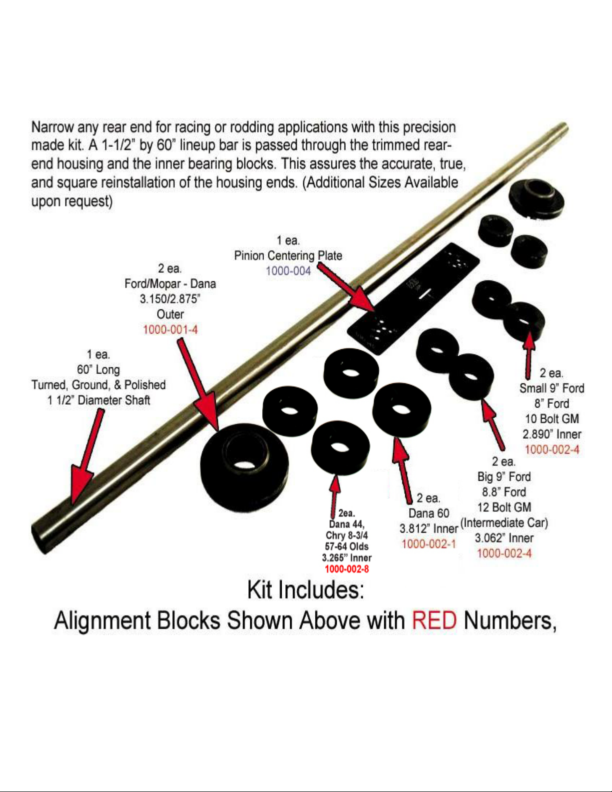
1000-RENK1 REAR END NARROWING KIT
USE OF THIS TOOL REQUIRES BASIC MATH AND WELDING SKILLS
Kit Contents
1ea 1000-001-2 Alignment Shaft - 60" long x 1-1/2" OD
1pr. 1000-001-4 Outer Line Up Ford / Dana
1pr. 1000-001-5 Outer Line Up GM / Ford
1pr. 1000-002-1 Dana 60 Inner Puck 3.812"
1pr. 1000-002-4 Big 9” Ford / GM 12 Bolt Inner Pucks
1pr. 1000-002-2 Small 9” Ford / GM 10 Bolt Inner Pucks
1pr. 1000-002-8 Dana 44 / Chrysler 8-3/4 / 57-64 Olds Inner Pucks
1ea. 1000-004 Pinion Centerline Gauge
SAFETY
• Wear protective clothing suitable for welding.
• Use a welding helmet with the correct shade of filter lens.
• Be sure housings are properly cleaned and degreased to remove flammables.
• Welding sparks can cause fires or explosions. Have a fire extinguisher nearby.
• Breathing welding fumes can be hazardous to your health. Be sure to have adequate ventilation.
PREPERATION
Fax: (636) 745-2874
1. Disassemble and clean housing. Use a good grease cutting solvent to remove the lube residue.
Follow this with warm soapy water, such as from the car wash.
a. On “Drop Out” style housings, such as 9” Ford, you must remove the “Drop Out” and then
clean the housing as described above. We recommend that you get a used “Drop Out”
from a junk yard and use this for your fixture case. This way you will only have minimal
work to re-setup your gears. Place the appropriate pucks into the carrier bearing locations.
Screw the bearing cap bolts finger tight. Slip the bar through the assembly and then tighten
the cap bolts. Remove the shaft.
b. On “One Piece” style housings, such as 12 Bolt & Dana, you will have to remove the ring
gear carrier assembly, be sure to keep track of any shims. With the ring gear carrier
assembly removed clean the housing as described above. Place the appropriate pucks
into the carrier bearing location. Screw the bearing cap bolts finger tight. Slide the bar
through the housing assembly and then tighten the cap bolts.
2. Determine the desired width, pinion offset and cut locations using the supplied work sheet. You
might want to make copies of the work sheet for future jobs. There is an example on the back of
the work sheet. This is a very critical step and care should be taken to get it right. Measure as
many times as needed to be sure that you have all the correct numbers before moving to the next
step.
N:\Product\Product Documentation\1000 Rear End\Narrowing Kit Instructions\1000-RENK1 Instructions.doc Rev1 3-01-2006
Page 2
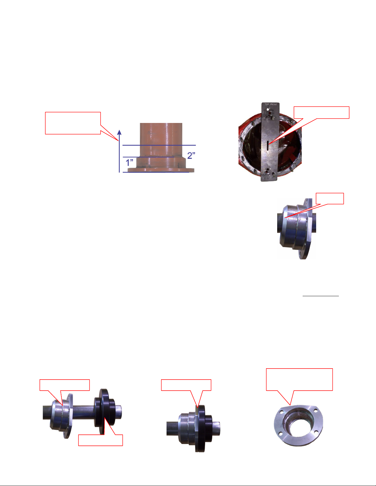
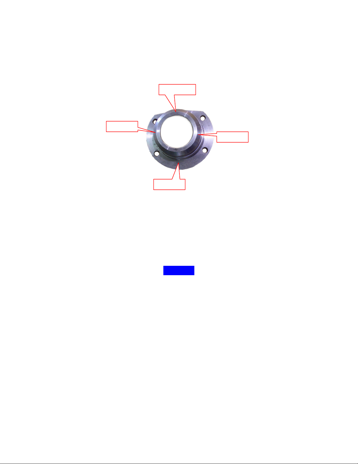
Pinion Centerline
Housing End
Bevel
Outer Puck
Slip Together
CUTTING
3. After you have determine the desired width, pinion offset and cut locations using the supplied
work sheet you are ready to cut the ends off of your housing. We recommend cutting the
exsisting ends off close to the bearing end between 1” & 2” back from the flange. If there are
seals in the end be sure to cut behind them. The best cuts will be made with a HORIZANTAL
BAND SAW or a CHOP SAW.
Cut 1” or 2” back
from end.
4. Bevel the housing tubes and the housing ends. This will assure a
quality weld joint. The amount of bevel will be determined by the
welding method, MIG or TIG. MIG will require a larger bevel than TIG.
POSITIONING
5. Slide the bar into the housing and through the inner alignment pucks. Be careful not to jam the
bar into the pucks as this may knock them loose or out of alignment. On “Drop Out” style
housings, be sure the carrier assembly is bolted into the housing with a gasket.
6. Slide the housing end onto the shaft followed by the appropriate outer line up puck. Slip the puck
into the housing end and then slide the assembly up to the end of the tube. Be sure to orient the
housing end correctly in relation to the housing. Check that the bolt pattern is aligned correctly for
the brakes you will be using.
Check Bolt Pattern
Check For Top
Page 3
4th Tack
3rd Tack
2nd Tack
1st Tack
WELDING
7. After you are sure that you have the correct dimensions and have the ends oriented correctly they
can be tack welded. We recommend that you tack them in at least 4 places. The tacks should be
located at 90° to each other. Tack both ends of the housing.
8. Double check all your measurements. When you are satisfied that every thing is correct go ahead
and finish weld the ends. We recommend that you weld ¼ of the way around at a time; weld from
tack 1 to tack 3 then tack 4 to tack 2. Move to the other housing end and follow the same
sequence. Now go back to the first end and weld from tack 1 to tack 4 and then tack 2 to tack 3
then move to the other end and complete the welding following the same sequence.
NOTICE
If you are going to be welding on brackets, back braces or other items we strongly suggest that
all of this welding be done prior to putting the housing ends on. By leaving the ends to the last
any heat induced warpage will be compensated for when the ends are installed. This will give
you best possible results and the straightest housing.
9. After all welding is complete let the housing cool to room temperature before handling. DO NOT
artificially cool the welds with water, air or any other method. Cooling to quickly may cause
weld cracking and result in failure.
We appreciate your business and hope that you enjoy your new Mittler Bros. Product. If you have any
questions or concerns please feel free to call us at 1-800-467-2464 for help.
Page 4
Page 5

Page 6

Page 7

Customer:
P
E
0 J2
2
- 0 6
3
2
-
Date:
1-800-467-2464
www.mittlerbros.com
0
.
1
ev.
R
t 0
k Shee
or
W
g Kit
n
rowi
a
N
\
d
En
r
a
0 r
0 Re
1
\
n
n 0
e tatio
cu
o
D
uct
rod
P
ct m
du \
P o
\ r
:
E
Housing Type ____________________________
Tubing End To Tubing End
Housing End To Housing End
Pinion Offset
To Driver Side
Axle Face to Axle Face
e
n
rlin
o
i
in
nte
P
e
C
Pinion Offset To
Passenger Side
Housing End
Thickness
Notes:______________________________________________
Axle Stand Out
Housing End Style ____________________________
Housing End Number ____________________________
Housing End Thickness ____________________________
____________________________________________________
____________________________________________________
____________________________________________________
Page 8

Customer:
Sample
Date:
1-800-467-2464
www.mittlerbros.com
25”
P
E
0 J2
2
- 0 6
3
2
-
0
.
1
ev.
R
t 0
k Shee
or
W
g Kit
n
rowi
a
N
\
d
En
r
a
0 r
0 Re
1
\
n
n 0
e tatio
cu
o
D
uct
rod
P
ct m
du \
P o
\ r
:
E
Housing Type ____________________________
Housing End Style ____________________________
22-1/2”
20-1/2”
Pinion Offset
To Driver Side
Tubing End To Tubing End
Housing End To Housing End
Axle Face to Axle Face
9” Ford
Old Style Big Ford
20-1/2”
e
n
rlin
o
i
in
nte
P
e
C
Pinion Offset To
Passenger Side
18-1/2”
1”
39”
43”
48”
Notes:______________________________________________
1” Pinion offset makes 2” difference
____________________________________________________
23”
Housing End
Thickness
2”
Axle Stand Out
2-1/2”
Housing End Number ____________________________
Housing End Thickness ____________________________
1000-253
2”
in measurement from pinion center
____________________________________________________
to either end
____________________________________________________
 Loading...