

Page 1

EN
Operating Manual
1 Usage
The anchor device (tripod DB UNI, DB MID, DB MINI, DB 500) is a part of the personal safety
equipment to protect against falling. It is used as an anchor point type B according to DIN EN 795. The
anchor device is authorised for use by a maximum of 2 persons. The catch systems to secure people
may only be attached to the provided anchor points (ring eyes on the tripod head). The two silvercoloured eyes on the bottom of the tripod head are for 2 people and the three yellow eyes to the side
of the tripod head are approved for one person. The tripod can only be used on a stable surface. The
anchor device may only be used for load lifting equipment. The equipment may only be used with a
catch belt according to EN 361. The connection between the anchor point and the personal safety
equipment must be via a connection element according to EN 362. For catch systems, it is extremely
important that the required clearance is ensured at the work are under the user before each use so
that, in the event of a fall, no impact onto the ground or another obstacle is possible. To rescue people
from shafts, containers or other lower level work levels, a rescue lifting device can be attached on the
tripod head or using an adapter DB on a leg of the tripod according to EN1496 such as LiftEvac,
Unidrive, MRG9 easy, MRG9easy+ or MRG9 lift. The rope of the rescue lifter is guided downward via
a guide roller attached to the silver-coloured anchor eye of the tripod head.
2 Technical specifications
Tripod DB UNI
- Completely demountable using a plug-in system
- Flexibly installable in 2 sizes (complete or half height)
- All legs can be telescoped in 5 stages
- 5 usable attachment eyelets on the tripod head
- Model with 3 folding feet or 3 round feet with ball joint
- 2 sets of guy ropes for complete or half installation height
- Height complete 215 – 240 cm, height half 120 – 145 cm
- Installation diameter complete 260 cm, half 140 cm
- Weight complete height 20.8 kg (with folding foot), 23.2 kg (with round foot)
- Weight complete height 13.1 kg (with folding foot), 15.6 kg (with round foot)
Tripod DB MID
- Completely demountable using a plug-in system
- All legs can be telescoped in 5 stages
- 5 usable attachment eyelets on the tripod head
- Model with 3 folding feet or 3 round feet with ball joint
- 1 set of guy ropes
- Height 120 – 145 cm
- Installation diameter 140 cm
- Weight 13.1 kg (with folding foot), 15.6 kg (with round foot)
Tripod DB MINI
- Completely demountable using a plug-in system
- All legs can be telescoped in 5 stages
- 5 usable attachment eyelets on the tripod head
- Model with 3 round feet with ball joint
- 1 set of guy ropes
- Height 86 – 114 cm
- Installation diameter 100 cm
- Weight 13.4 kg
Tripod DB 500
- Completely demountable using a plug-in system
Page 2

- All legs can be telescoped in 5 stages
- 5 usable attachment eyelets on the tripod head
- Model with 3 folding feet
- 1 set of guy ropes
- Height 215 cm
- Installation diameter 260 cm
- Weight 19.8 kg
3 Installation
3.1 Version Tripod DB UNI and DB 500
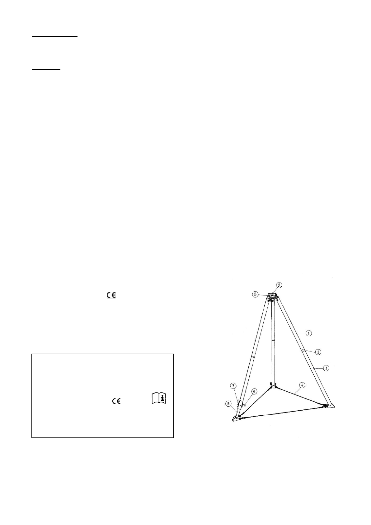
The tube tops item 1 (position numbers cf. Figure 1) are attached using the lock pin with a yellow
anchor eye item 8 on the tripod head item 9. Insert the tube bottoms item 3 into the tube top item 1 and
lock it with a spring catch item 2. Insert the telescopic foot or the telescopic feet item into the tube
bottoms and lock with the lock pin item 6 and spring catch item 7 in the desired position. Connect the
feet of the tripod to the wire cables item 4. Spread out the tripod until the wire cables item 4 are
tensioned. Alternative to the wire cables, the tripod legs can also be connected with special connection
tubes and clamps. A major prerequisite for the secure function of the anchor device is the safety of the
tripod. Uneven surfaces can be compensated for with the adjustment foot (feet) item 5. To do this,
slacken the wire pin item 7, remove the lock pin item 6 and bring the adjustment tube into the
appropriate position. Here a bore in the tube of the adjustment foot must be flush with the bore in the
bottom of the tube. Now insert the lock pin and secure with the wire pin while pulling outward. When
erecting the tripod, it should be ensured that the standing feet are lying flat on the ground with its
standing surface. For the round feet, ensure when erecting that the ball joints are not tensioned. The
ball joints are only to be tensioned when the standing areas of the round feet are lying flat on the
ground.
For the tripod DB UNI, the adjustment feet can also be inserted without the tube bottoms directly into
the tube tops and secured with lock pins and wire pins. As a result, the tripod can be used with one
half installation height.
3.2 Version of tripod DB UNI and DB 500
The tube tops item 1 (position numbers cf. Figure 1) are attached using the lock pin with a yellow
anchor eye item 8 on the tripod head item 9. Insert the telescopic foot or the telescopic feet item into
the tube bottoms and lock with the lock pin item 6 and spring catch item 7 in the desired position.
Connect the feet of the tripod to the wire cables item 4. Spread out the tripod until the wire cables item
4 are tensioned. Alternative to the wire cables, the tripod legs can also be connected with special
connection tubes and clamps. A major prerequisite for the secure function of the anchor device is the
safety of the tripod. Uneven surfaces can be compensated for with the adjustment feet item 5. To do
this, slacken the wire pin item 7, remove the lock pin item 6 and bring the adjustment tube into the
appropriate position. Here a bore in the tube of the adjustment foot must be flush with the bore in the
bottom of the tube. Now insert the lock pin and secure with the wire pin while pulling outward. When
erecting the tripod, it should be ensured that the standing feet are lying flat on the ground with its
standing surface. For the round feet, ensure when erecting that the ball joints are not tensioned. The
ball joints are only to be tensioned when the standing areas of the round feet are lying flat on the
ground.
The following applies to all versions of the tripod.
The arrest system for the fall protection of one person and/or the rescue device can now be attached
to the respective attachment eyelet of the tripod-head. As an alternative the rescue device can be
attached to one of the tripod’s legs by means of an adapter. To this end proceed as follows:
Unscrew the bolt with the black handle from the adaptor. Insert the descent device certified for use with
the adaptor with the shackle (without the snaphook) in the aperture of the adaptor, re-introduce the bolt
into the adaptor passing it through the shackle and screw it tightly in the baseplate again. The descent
device has thus been attached to the adaptor. The adaptor can be equipped with either 2 clamps or 2
screw terminals .
Procedure for the use of the clamps: open the clamps by unclasping and position on a leg of the tripod,
first close the middle clamp around the leg of the tripod, then position the upper clamp over the middle
clamp and close. The upper clamp is attached to an eyebolt which can rotate in the opened position.
Turning this element can adjust the clamping force. By turning right the force is increased and by
turning left the force is reduced. The clamps must close securely and the adaptor must be positioned
firmly on the tripod’s leg.
Page 3

Procedure for the use of the screw terminals: open the clamps by unclasping and position on a leg of
the tripod, put the movable clamp around the leg and close by means of the hinged rotating handle. In
this position the half-moon bolt should rest on the movable clamp. Fasten the clamps by turning the
rotating handles to the right. The adaptor must be positioned firmly on the tripod’s leg.
Pass the rope of the rescue device through the pulley and attach the pulley to the silver colored
attachment eye on the tripod’s head. The rope can now be passed downward through the pulley.
Here please follow the operating manuals of the products used.
If the anchor device is used as a part of the catch system, the user must be equipped with a means
that limits the maximum dynamic forces that affect the user during the catch process to a maximum of
6 kN. For safety, it is essential that the position of the anchor device and the type of the work model be
selected in such a way that a free fall and the fall height are limited to a minimum. Connection devices
with a fall insulator must be connected in such a way that the function of the fall insulator is not impeded.
Protect cables and belts from sharp-edged objects, welding sparks, chemicals or other destructive or
damaging hazards. Before initial usage, become familiar with the function. Before and during usage,
consider how any rescue actions that may be necessary can be performed safely, quickly and
effectively. The anchor device may only be installed and used by trained and/or otherwise specialized
personnel. The anchor device may only be used within the scope of the specified terms of use and for
the intended purpose. A rescue action plan must be in place in which all of the emergencies possible
during work are taken into account. Health restrictions such as cardio and circulation problems, taking
medication etc. can negatively impact the user when working at heights. With a combination of machine
parts for a system, it should always be ensured that the functions of the individual equipment parts are
not impeded. If the anchor device is sold to another country, the reseller must provide a manual for the
usage, service and regular inspection in the national language.
4 Meaning of the designation
The user must read and following the operating manual!
Anchor device type B Type of the anchor device according to DIN EN 795:2012
Tripod DB UNI, DB MID, Type designation of the anchor device
DB MINI, DB 500
Mittelmann Sicherheitstechnik Manufacturer instructions
GmbH & Co. KG
Bessemerstraße 25
42551 Velbert
www.mittelmann.com Internet address of the manufacturer
Serial no. xxxxx Product serial number
2 people Number of persons who can be secured simultaneously
on the anchor device.
Year of manufacture: XX/XXXX Manufactured in the month/year
DIN EN795:2012 Number and year of the document that corresponds to the
equipment
CEN/TS 16415:2017 Recommendations for the use of anchor devices at the same
time for several persons
0158 Identification number of the monitoring entity
4 Material specifications
The tripod is composed of aluminium, steel and stainless steel.
5 Service and storage
After finishing work, clean and dry the anchor device and store in ventilated and shaded rooms.
During transport of the anchor device, it should be stored in a suitable transport container (e.g.
equipment bag).
Avoid contact with acids, caustic liquids and oils. If unavoidable, clean with a lot of water (40°C) as
quickly as possible. Always dry in a natural manner, never near fire or other heat sources.
For questions on disinfecting the anchor device, please contact the manufacturer.
Attention: Strictly observe the cleaning instructions!!
Page 4
6 Service life
The service life of the anchor device depends on the respective terms of usage. The technically
seamless state of the complete anchor device is decisive for the usage period.
7 Check
Before beginning work, check the anchor device for wear or damages. Check for the proper function
of the anchor device. Check the legibility of the label. The anchor device should be labelled with the
date of the next or last inspection.
If there are any doubts on the secure status of the system or the components, they should be replaced
immediately. This must be performed by the manufacturer or another specialist.
Inspection of certain equipment parts intended for emergencies can be omitted before usage if they
are inspected by specialized personnel and then packed and sealed.
If necessary, have a check performed at least once a year by the manufacturer or a specialist. The
annual inspection by the manufacturer or a specialist is essential because the safety of the user
depends on the effectiveness and service life of the equipment. The checks are to be performed with
strict compliance with the manufacturer instructions.
Attention: Damaged equipment may not be used.
Systems put under stress from falls are to be removed from usage and are to be returned to the
manufacturer or an authorized repair shop for service and a new inspection. It may only be used
following written permission by a specialist.
Attention: No changes or enhancements may be made to the product without the prior
written permission of the manufacturer.
Maintenance may only be performed by the manufacturer or by a repair shop
authorised by the manufacturer in coordination with the processes indicated by
the manufacturer.
The operating manual / test log must be used for each anchor device. It must be kept with the
equipment.
Please always follow the operating instructions of the products that are used in conjunction with the
anchor device as well as the generally applicable accident prevention regulations.
Involved notified entity: DEKRA Testing and
Certification GmbH 0158
Dinnendahlstraße 9
44809 Bochum
Illustration of the label:
Figure 1
Dreibaum DB UNI, DB MID, DB MINI, DB 500
Tripod DB UNI, DB MID, DB MINI, DB 500
Anschlageinrichtung Typ B EN795:2012
Anchor device type B CEN/TS 16415:2017
2 Personen Baujahr: xx/xxxx
2 persons Year of manufacture
Serial no.: xxxxxxxxxx 0158
Serial number
Mittelmann Sicherheitstechnik GmbH & Co. KG
Bessemerstraße 25, 42551 Velbert
www.mittelmann.com
Page 5
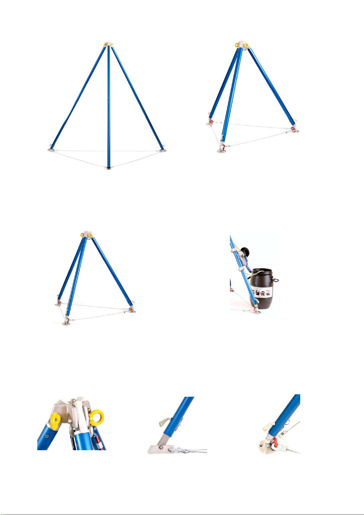
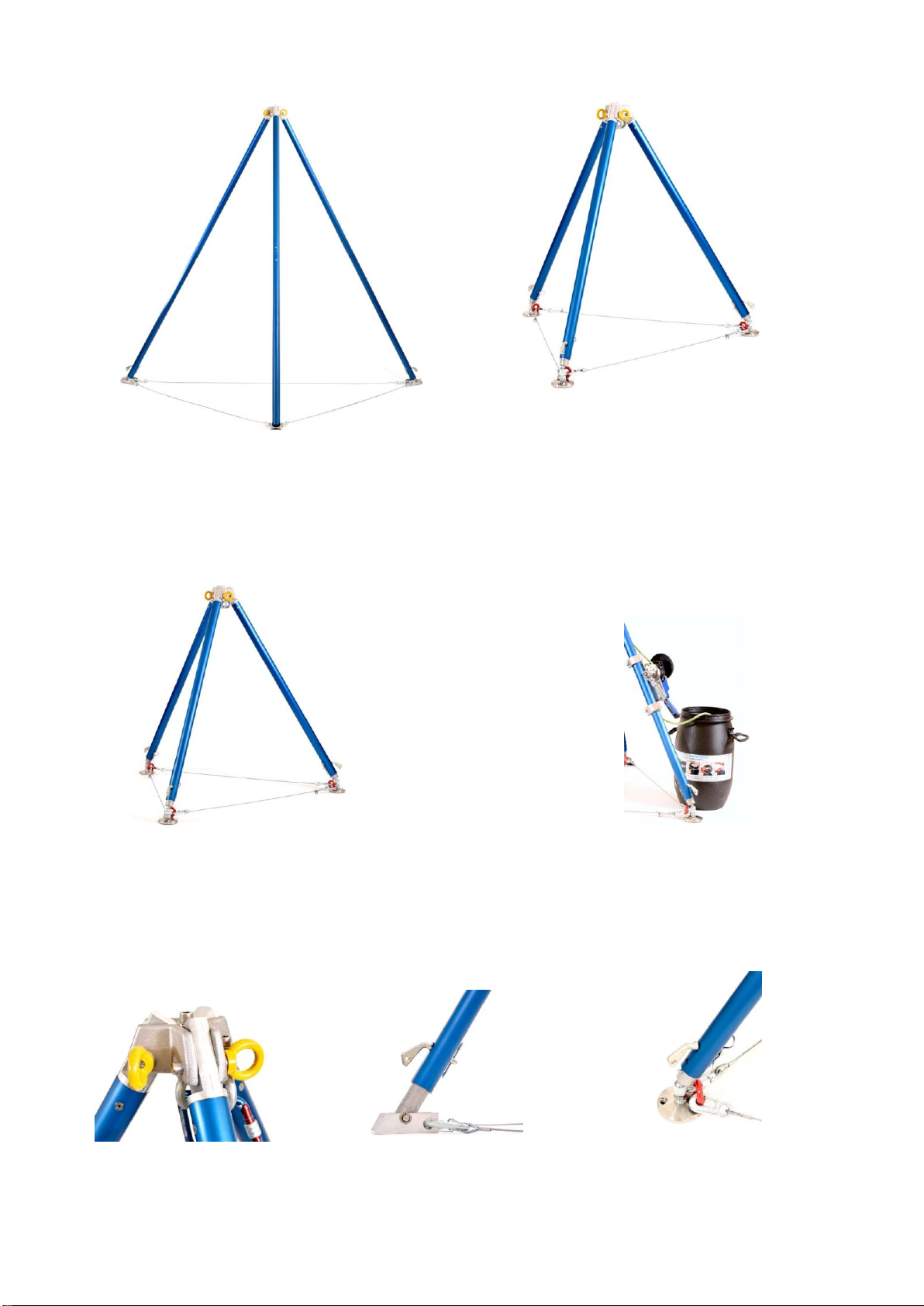
Tripod DB UNI (3 legs telescopable) Tripod DB MID
Tripod DB 500 (1 leg telescopable) Figure 3
Figure 2
Tripod DB MINI Tripod with adapter for rescue device
Figure 4 Figure 5
Tripod head Folding foot Round foot
Figure 6 Figure 7 Figure 8
Page 6
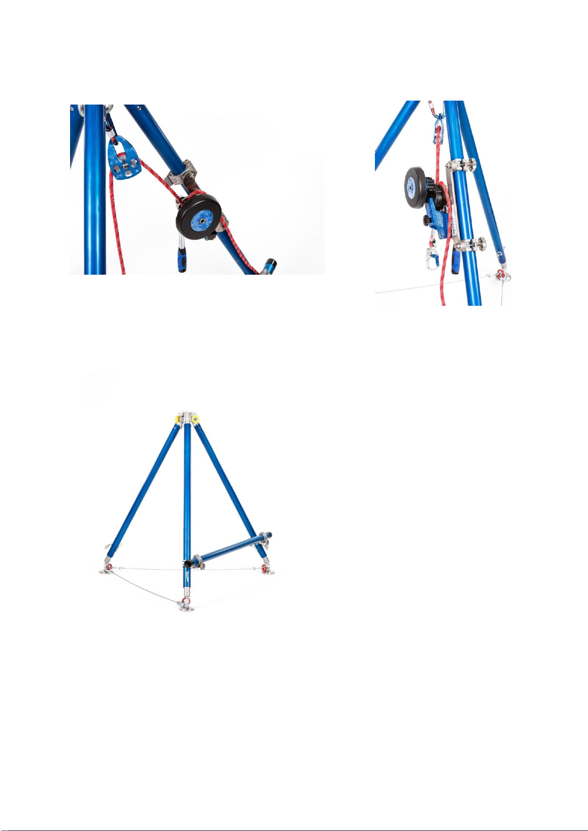
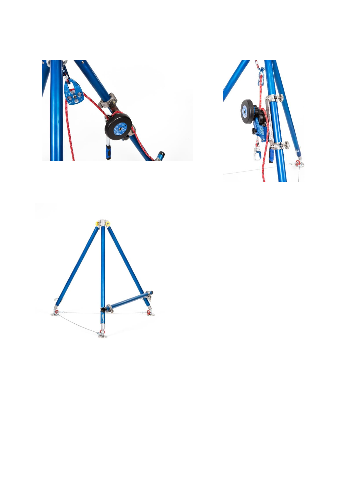
Adapter with clamps Adapter with screw terminals
Figure 9 Figure 10
Tripod with transverse pipes
Figure 11
Last update: 12.12.2018
Page 7

SV
Bruksanvisning
1. Användning
Förankringsanordningen (tripod UNI, DB MID, DB MINI, DB 500) är en del av den personliga
fallskyddsutrustningen. Den används som förankringspunkt av typ B enligt DIN EN 795. Förankringen
är godkänd för användning av högst 2 personer. Fallskydd för säkring av flera personer får endast
fästas i de medföljande förankringspunkterna (ringbultarna på tripodens huvud). De två silverfärgade
ringarna längst ned på tripoden är avsedda för 2 personer och de tre gula ringarna på tripodens sida
är godkända för en person. Tripoden får endast användas på stadigt underlag. Förankringen får
endast användas för lastutrustning. Utrustningen får endast användas med fallskyddslinor som
överensstämmer med EN 361. Kopplingen mellan förankringen och den personliga
skyddsutrustningen måste överensstämma med EN 362. När det gäller fallskydd är det extremt
viktigt att man, innan arbetet inleds, kontrollerar att den fria höjden är tillräcklig så att användaren inte
kan slå i marken eller andra föremål vid ett eventuellt fall. För evakuering av personer från schakt,
containrar eller andra arbetsplatser på lägre höjd kan en räddningsanordning fästas i tripodens huvud
eller, med en DB-adapter, på tripodens ben i enlighet med EN1496, t.ex. LiftEvac, UniDrive, MRG9
easy, MrG9easy+ eller MRG9 lift. Räddningsrepet matas ned via ett block som fästs i den
silverfärgade förankringsöglan på tripodens huvud.
2. Tekniska specifikationer
Tripod DB UNI
- Kan demonteras helt med ett plugin-system
- Flexibel installation i 2 olika storlekar (full eller halv höjd)
- Alla ben är 5-delade teleskopben
- 5 fästöglor på tripodens huvud
- Modell med 3 vikbara fötter eller 3 runda fötter med kulleder
- 2 uppsättningar staglinor för installation i halv eller full höjd
- Full höjd: 215–240 cm, halv höjd 120–145 cm
- Diameter full höjd: 260 cm; halv höjd: 140 cm
- Vikt full höjd: 20,8 kg (med vikbara fötter), 23,2 kg (med runda fötter)
- Vikt full höjd: 13,1 kg (med vikbara fötter), 15,6 kg (med runda fötter)
Tripod DB MID
- Kan demonteras helt med ett plugin-system
- Alla ben är 5-delade teleskopben
- 5 fästöglor på tripodens huvud
- Modell med 3 vikbara fötter eller 3 runda fötter med kulleder
- 1 uppsättning staglinor
- Höjd 120–145 cm
- Diameter 140 cm
- Vikt 13,1 kg (med vikbara fötter), 15,6 kg (med runda fötter)
Tripod DB MINI
- Kan demonteras helt med ett plugin-system
- Alla ben är 5-delade teleskopben
- 5 fästöglor på tripodens huvud
- Modell med 3 runda fötter med kulleder
- 1 uppsättning staglinor
- Höjd 86–114 cm
- Diameter 100 cm
- Vikt 13,4 kg
Tripod DB 500
- Kan demonteras helt med ett plugin-system
Page 8

- Alla ben är 5-delade teleskopben
- 5 fästöglor på tripodens huvud
- Modell med 3 vikbara fötter
- 1 uppsättning staglinor
- Höjd 215 cm
- Diameter 260 cm
- Vikt 19,8 kg
3. Installation
3.1 Tripodversion DB UNI och DB 500
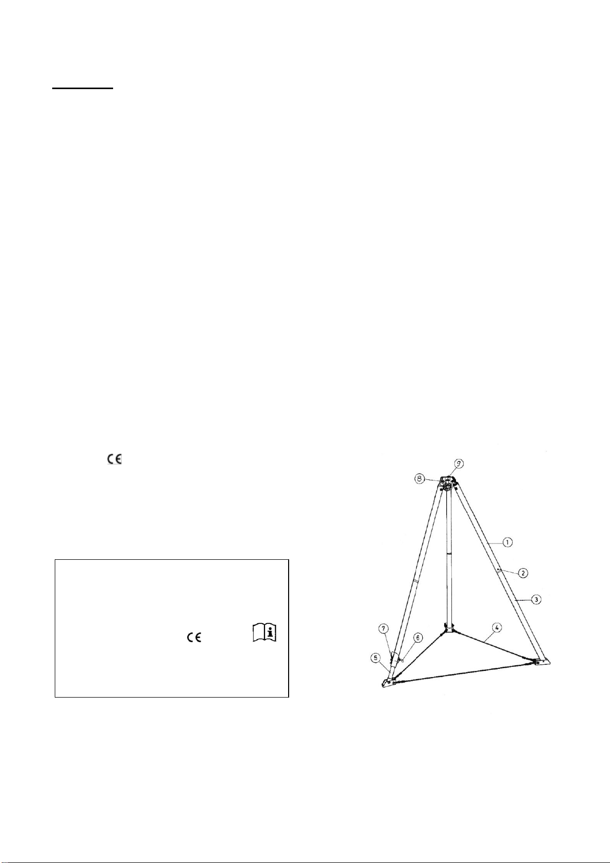
De övre rördelarna nr 1 (för komponentnummer, se Bild 1) fästs med låssprinten med gul
förankringsögla nr 8 på tripodens huvud nr 9. För in de nedre rördelarna nr 3 i de övre rördelarna nr 1
och lås med fjäderlås nr 2. För in teleskopfoten eller teleskopfötterna i de nedre rördelarna och lås
med låssprint nr 6 och fjäderlås nr 7 i önskat läge. Koppla fast tripodens fötter i vajrarna nr 4. Sära på
tripodens ben tills vajrarna nr 4 är spända. Istället för att kopplas till vajrarna kan tripodens ben fästas
med särskilda kopplingsrör och klämmor. En viktig förutsättning för att förankringen ska fungera
tillförlitligt är tripodens säkerhet. Om underlaget är ojämnt kan detta kompenseras med justeringsfot
(-fötter) nr 5. Gör så här: Lossa vajerstift nr 7, ta bort låssprint nr 6 och sätt justeringsröret i rätt läge.
Ett hål i justeringsfotens rör måste passas in mot hålet på rörets nedre del. Sätt i låssprinten och fäst
med vajerstiftet samtidigt som du drar utåt. När du reser tripoden måste du se till att fötternas stödyta
ligger plant mot underlaget. Om tripoden har rundade fötter måste du se till att kullederna inte är
sträckta när du reser den. Kullederna ska endast sträckas när de rundade fötternas stödyta ligger
plant mot underlaget.
På tripodmodell DB UNI kan justeringsfötterna också föras in direkt i de övre rördelarna utan de
nedre rördelarna och fästas med låssprintar och vajerstift. På så sätt kan tripoden användas i halv
installationshöjd.
3.2 Tripodversion DB UNI och DB 500
De övre rördelarna nr 1 (för komponentnummer, se Bild 1) fästs med låssprinten med gul
förankringsögla nr 8 på tripodens huvud nr 9. För in teleskopfoten eller teleskopfötterna i de nedre
rördelarna och lås med låssprint nr 6 och fjäderlås nr 7 i önskat läge. Koppla fast tripodens fötter i
vajrarna nr 4. Sära på tripodens ben tills vajrarna nr 4 är spända. Istället för att kopplas till vajrarna
kan tripodens ben fästas med särskilda kopplingsrör och klämmor. En viktig förutsättning för att
förankringen ska fungera tillförlitligt är tripodens säkerhet. Om underlaget är ojämnt kan detta
kompenseras med justeringsfötter nr 5. Gör så här: Lossa vajerstift nr 7, ta bort låssprint nr 6 och sätt
justeringsröret i rätt läge. Ett hål i justeringsfotens rör måste passas in mot hålet på rörets nedre del.
Sätt i låssprinten och fäst med vajerstiftet samtidigt som du drar utåt. När du reser tripoden måste du
se till att fötternas stödyta ligger plant mot underlaget. Om tripoden har rundade fötter måste du se till
att kullederna inte är sträckta när du reser den. Kullederna ska endast sträckas när de rundade
fötternas stödyta ligger plant mot underlaget.
Följande gäller alla tripodversioner:
Falldämparen/fallskyddet för en person och/eller räddningsanordningen kan nu fästas i respektive
fästögla på tripodens huvud. Alternativt kan räddningsanordningen fästas i ett av tripodens ben med
hjälp av en adapter. Gör så här:
Lossa skruven med det svarta handtaget på adaptern. För in en firningsanordning som är certifierad
för användning med adaptern med schackeln (utan hake) i adapterns öppning. Fäst skruven i
adaptern igen genom att föra den genom schackeln och skruva fast den ordentligt i bottenplattan
igen. Firningsanordningen är nu fäst i adaptern. Adaptern kan förses med 2 klämfästen eller 2
skruvfästen.
Så här använder du klämfästen: Öppna klämfästena och placera dem runt ett av tripodens ben.
Stäng först det mellersta klämfästet runt tripodens ben. Sätt sedan det övre klämfästet över det
mellersta klämfästet och stäng det. Det övre klämfästet har en öglebult som kan rotera i öppet läge.
Genom att vrida på denna kan du reglera klämkraften. Om du vrider den åt höger ökar kraften och
om du vrider den åt vänster minskar kraften. Klämfästena måste stängas helt och adaptern måste
fästas ordentligt på tripodens ben.
Så här använder du skruvfästen: Öppna fästena och placera dem på ett av tripodens ben. Sätt den
flyttbara klämman runt benet och stäng den med det gångjärnsförsedda vridhandtaget. I denna
position ska den halvmåneformade bulten vila på den flyttbara klämman. Fäst klämmorna genom att
vrida vridhandtaget åt höger. Adaptern måste fästas ordentligt på tripodens ben.
Page 9

Dra räddningsrepet genom blocket och fäst blocket i den silverfärgade fästöglan på tripodens huvud.
Repet kan nu matas ned genom blocket.
Följ bruksanvisningarna för de produkter som används.
Om förankringen används som en del av fallskyddet måste användaren ha en anordning som
begränsar den maximala dynamiska belastning som användaren kan utsättas för vid ett eventuellt fall
till 6 kN. Av säkerhetsskäl är det viktigt att förankringens placering och den valda arbetsmodellen
minimerar det fria fallet och fallhöjden. Kopplingsanordningar med falldämpare ska kopplas in på ett
sådant sätt att falldämparens funktion inte begränsas. Vajrar och linor ska skyddas mot vassa
föremål, svetsloppor, kemikalier och andra skadliga föremål och faror. Bekanta dig med systemets
funktion före det första användningstillfället. Fundera hur eventuella nödvändiga räddningsaktioner
kan utföras säkert, snabbt och effektivt före och under användning. Förankringen får endast
installeras och användas av utbildad och/eller på annat sätt specialiserad personal. Förankringen får
endast användas enligt fastställda användningsvillkor och för avsett syfte. En räddningsplan måste
finnas på plats som beaktar alla nödsituationer som kan uppstå under arbetet. Hälsorelaterade
faktorer som hjärt- och cirkulationsproblem, medicinering etc. kan ha negativ inverkan på användaren
vid arbete på hög höjd. Med en kombination av maskindelar för ett system bör du alltid kontrollera att
de enskilda utrustningskomponenternas funktioner inte hindras. Om förankringen säljs till ett annat
land måste återförsäljaren tillhandahålla instruktioner för användning, underhåll och regelbunden
kontroll på det nationella språket.
4. Beteckningens innebörd
Användaren måste läsa och följa bruksanvisningen!
Förankringsanordning typ B Typ av förankringsanordning enligt DIN EN 795:2012
Tripod DB UNI, DB MID, Förankringens typbeteckning
DB MINI, DB 500
Mittelmann Sicherheitstechnik Tillverkarens anvisningar
GmbH & Co. KG
Bessemerstraße 25
42551 Velbert, Tyskland
www.mittelmann.com Tillverkarens webbplats
Serienr xxxxx Produktens serienummer
2 personer Antal personer som kan säkras samtidigt
i förankringen.
Tillverkningsår: XX/XXXX Tillverkad månad/år
DIN EN795:2012 Nummer och årtal för det dokument som avser utrustningen.
CEN/TS 16415:2017 Rekommendationer avseende användning av
förankringsanordningar för flera personer samtidigt
0158 Tillsynsorganets id-nummer
4. Materialspecifikationer
Tripoden är tillverkad i aluminium, stål och rostfritt stål.
5. Underhåll och förvaring
Efter avslutat arbete ska förankringen rengöras och torkas och sedan förvaras i ett välventilerad och
solskyddat utrymme.
När förankringen transporteras ska den förvaras i en lämplig transportbehållare (t.ex. en
utrustningspåse).
Undvik kontakt med syror, frätande vätskor och oljor. Om det inte kan undvikas ska utrustningen
rengöras med rikligt med vatten (40 °C) så snabbt som möjligt. Låt alltid förankringen självtorka; lägg
den aldrig nära eld eller andra värmekällor.
Kontakta tillverkaren om du har frågor kring desinficering av förankringen.
Obs! Följ rengöringsanvisningarna noggrant!
6. Brukbarhetstid
Page 10
Förankringens brukbarhetstid beror på användningsförhållandena. Förankringsanordningens
tekniska helhetsstatus avgör hur länge den kan användas.
7. Kontroll
Innan arbetet påbörjas ska förankringen kontrolleras med avseende på slitage och skador.
Kontrollera att förankringen fungerar som den ska. Kontrollera att etiketten är läsbar. Förankringen
ska vara märkt med datum för nästa eller senaste inspektion.
Vid eventuell osäkerhet kring systemets eller komponenternas säkerhetsstatus ska de bytas ut
omedelbart. Det måste göras av tillverkaren eller en annan specialist.
Vissa utrustningskomponenter för nödsituationer behöver inte kontrolleras före användning om de
har kontrollerats av specialiserad personal och därefter förpackats och förslutits.
Om nödvändigt ska utrustningen kontrolleras minst en gång per år av tillverkaren eller en specialist.
Tillverkarens eller specialistens årliga inspektion är mycket viktig eftersom användarens säkerhet är
avhängig utrustningens effektivitet och brukbarhetstid. Kontrollerna ska utföras exakt enligt
tillverkarens instruktioner.
Obs! Skadad utrustning får inte användas.
System som har belastats genom fall ska tas ur bruk och returneras till tillverkaren eller en
auktoriserad verkstad för underhåll och inspektion. De får endast användas enligt skriftligt tillstånd
från en specialist.
Obs! Inga ändringar eller förbättringar för göras på produkten utan föregående
skriftligt tillstånd från tillverkaren.
Underhåll får endast utföras av tillverkaren eller en verkstad som har
auktoriserats av tillverkaren i enlighet med de processer som tillverkaren har
fastställt.
Bruksanvisningen/testloggen ska användas för alla förankringar. Den måste förvaras tillsammans
med utrustningen.
Följ alltid bruksanvisningarna för produkter som används tillsammans med förankringen samt allmänt
tillämpliga rutiner för olycksförebyggande.
Berört anmält organ: DEKRA Testing and Certification
GmbH 0158
Dinnendahlstraße 9
44809 Bochum, Tyskland
Etikett på produkten:
Bild 1
Dreibaum DB UNI, DB MID, DB MINI, DB 500
Tripod DB UNI, DB MID, DB MINI, DB 500
Anschlageinrichtung Typ B EN795:2012
Förankringsanordning typ B CEN/TS
16415:2017
2 Personen Baujahr: xx/xxxx
2 personer Tillverkningsår
Serienr: xxxxxxxxxx 0158
Serienummer
Mittelmann Sicherheitstechnik GmbH & Co. KG
Bessemerstraße 25, 42551 Velbert, Tyskland
Page 11
Tripod DB UNI (tre teleskopben) Tripod DB MID
Tripod DB 500 (1 teleskopben) Bild 3
Bild 2
Tripod DB MINI Tripod med adapter för räddningsanordning
Bild 4 Bild 5
Tripodens huvud Vikbar fot Rund fot
Bild 6 Bild 7 Bild 8
Page 12
Adapter med klämfästen Adapter med skruvfästen
Bild 9 Bild 10
Tripod med tvärgående rör
Bild 11
Senast uppdaterad: 12.12.2018
 Loading...