

Page 1
MELSEC-QS CC-Link IE Field Network Master/
Local Module
User's Manual
-QS0J71GF11-T2
Page 2

Page 3
SAFETY PRECAUTIONS
WARNING
CAUTION
Indicates that incorrect handling may cause hazardous conditions,
resulting in death or severe injury.
Indicates that incorrect handling may cause hazardous conditions,
resulting in minor or moderate injury or property damage.
(Read these precautions before using this product.)
Before using this product, please read this manual and the relevant manuals carefully and pay full attention
to safety to handle the product correctly.
The precautions given in this manual are concerned with this product only. For the safety precautions of the
programmable controller system, refer to the user's manual for the CPU module used.
In this manual, the safety precautions are classified into two levels: " WARNING" and " CAUTION".
Under some circumstances, failure to observe the precautions given under " CAUTION" may lead to
serious consequences.
Observe the precautions of both levels because they are important for personal and system safety.
Make sure that the end users read this manual and then keep the manual in a safe place for future
reference.
[Design Precautions]
WARNING
● When a safety programmable controller detects an error in an external power supply or a failure in
programmable controller main module, it turns off all the outputs. Create an external circuit to securely
stop the power of hazard by turning off the outputs. Incorrect configuration may result in an accident.
● To inhibit restart without manual operation after safety functions was performed and outputs were
turned off, create an interlock program which uses a reset button for restart.
● If CC-Link IE Field Network error has been detected, create a sequence program that turns off the
outputs in the program. If the CC-Link IE Field Network is restored with the outputs on, it may
suddenly operate and result in an accident.
[Design Precautions]
CAUTION
● Do not bunch the wires of external devices or communication cables together with the main circuit or
power lines, or install them close to each other. They should be installed 100 mm (3.94 inch) or more
from each other. Not doing so could result in noise that would cause malfunctions.
1
Page 4
[Installation Precautions]
CAUTION
● Use a safety programmable controller in the environment that meets the general specifications
described in the QSCPU User's Manual (Hardware Design, Maintenance and Inspection). Using this
programmable controller in an environment outside the range of the general specifications could
result in electric shock, fire, erroneous operation, and damage to or deterioration of the product.
● While pressing the installation lever located at the bottom of module, insert the module fixing tab into
the fixing hole in the base unit until it stops. Then, securely mount the module with the fixing hole as a
supporting point. Incorrect loading of the module can cause a failure or drop. Secure the module to
the base unit with screws. Tighten the screw in the specified torque range. If the screws are too loose,
it may cause a drop of the screw or module. Overtightening may cause a drop due to the damage of
the screw or module.
● Completely turn off the external supply power used in the system before mounting or removing the
module. Not doing so could result in damage to the product.
● Do not directly touch the module's conductive parts or electronic components. Doing so may cause
malfunctions or a failure.
[Wiring Precautions]
WARNING
● Be sure to shut off all phases of the external supply power used by the system before wiring. Not
completely turning off all power could result in electric shock or damage to the product.
● When energizing or operating the module after installation or wiring, be sure to close the attached
terminal cover. Not doing so may result in electric shock.
2
Page 5

[Wiring Precautions]
CAUTION
● Tighten a module fixing screw within the specified torque range. If the module fixing screw is too
loose, it may cause a drop of the screw or module. Overtightening the screw may cause a drop due to
the damage of the screw or module.
● Be sure there are no foreign substances such as sawdust or wiring debris inside the module. Such
debris could cause a fire, failure, or malfunctions.
● The module has an ingress prevention label on its top to prevent foreign matter, such as wire chips,
from entering the module during wiring. Do not peel this label during wiring. Before starting system
operation, be sure to peel this label because of heat dissipation.
● Be sure to fix the communication cables or power cables by ducts or clamps when connecting them to
the module. Failure to do so may cause damage of the module or cables due to a wobble,
unintentional shifting, or accidental pull of the cables, or malfunctions due to poor contact of the cable.
● When removing the connected communication cables or power cables, do not pull the cable with
grasping the cable part. Pulling the cable connected to a module may result in malfunctions or
damage of the module or cable.
● For the cables to be used in CC-Link IE Field Network, use the ones specified by the manufacturer.
Otherwise, the performance of CC-Link IE Field Network is not guaranteed. As to the maximum
overall cable length and station - to station cable length, follow the specifications described in the
MELSEC-QS CC-Link IE Field Network Master/Local Module User's Manual. If not following the
specification, the normal data transmission is not guaranteed.
3
Page 6
[Startup and Maintenance Precautions]
WARNING
● Turn off all phases of the external supply power used in the system when cleaning the module or
retightening the module fixing screws. Not doing so could result in electric shock.
Tighten a fixing screw within the specified torque range. If the module fixing screw is too loose, it may
cause a drop of the screw or module. Overtightening the screw may cause a drop due to the damage
of the screw or module.
[Startup and Maintenance Precautions]
CAUTION
● Do not disassemble or modify the modules. Doing so could cause a failure, malfunctions, injury, or
fire. If the product is repaired or remodeled by other than the specified FA centers or us, the warranty
is not covered.
● Completely turn off the external supply power used in the system before mounting or removing the
module. Not doing so may result in a failure or malfunctions of the module.
● Restrict the mounting/removal of a module, base unit, and terminal block up to 50 times
(IEC61131-2 compliant), after the first use of the product.
Failure to do so may cause the module to malfunction due to poor contact of connector.
● Before touching the module, always touch grounded metal, etc. to discharge static electricity from
human body, etc. Not doing so may result in a failure or malfunctions of the module.
[Disposal Precautions]
CAUTION
● When disposing of this product, treat it as industrial waste. When disposing of batteries, separate
them from other wastes according to the local regulations. (For details of the Battery Directive in EU
member states, refer to the QSCPU User's Manual (Hardware Design, Maintenance and Inspection).)
4
Page 7

CONDITIONS OF USE FOR THE PRODUCT
(1) Although MELCO has obtained the certification for Product's compliance to the international safety
standards IEC61508, EN954-1/ISO13849-1 from TUV Rheinland, this fact does not guarantee that
Product will be free from any malfunction or failure. The user of this Product shall comply with any
and all applicable safety standard, regulation or law and take appropriate safety measures for the
system in which the Product is installed or used and shall take the second or third safety measures
other than the Product. MELCO is not liable for damages that could have been prevented by
compliance with any applicable safety standard, regulation or law.
(2) MELCO prohibits the use of Products with or in any application involving, and MELCO shall not be
liable for a default, a liability for defect warranty, a quality assurance, negligence or other tort and a
product liability in these applications.
(a) power plants,
(b) trains, railway systems, airplanes, airline operations, other transportation systems,
(c) hospitals, medical care, dialysis and life support facilities or equipment,
(d) amusement equipments,
(e) incineration and fuel devices,
(f) handling of nuclear or hazardous materials or chemicals,
(g) mining and drilling,
(h) and other applications where the level of risk to human life, health or property are elevated.
5
Page 8

INTRODUCTION
Thank you for purchasing the Mitsubishi MELSEC-QS series programmable controllers.
This manual describes the overview of the CC-Link IE Field Network, and operating procedure, system configuration,
parameter setting, functions, programming, and troubleshooting of the QS0J71GF11-T2, CC-Link IE Field Network
master/local module (hereafter abbreviated as master/local module).
Before using this product, please read this manual and the relevant manuals carefully and develop familiarity with the
functions and performance of the MELSEC-QS series programmable controller to handle the product correctly.
When applying the program examples introduced in this manual to the actual system, ensure the applicability and
confirm that it will not cause system control problems.
Please make sure that the end users read this manual.
COMPLIANCE WITH THE EMC, LOW VOLTAGE, AND
MACHINERY DIRECTIVES
(1) Method of ensuring compliance
To ensure that Mitsubishi programmable controllers maintain EMC, Low Voltage, and Machinery Directives when
incorporated into other machinery or equipment, certain measures may be necessary. Please refer to one of the
following manuals.
• QSCPU User's Manual (Hardware Design, Maintenance and Inspection)
• Safety Guidelines
(This manual is included with the base unit.)
The CE mark on the side of the programmable controller indicates compliance with EMC, Low Voltage, and
Machinery Directives.
(2) For the product
This product complies with the EMC, Low Voltage, and Machinery Directives. Before using this product, please
read this manual, the relevant manuals, the manuals for standard programmable controllers, and the safety
standards carefully and pay full attention to safety to handle the product correctly.
The descriptions are based on the requirements of the Directives and the harmonized standards. However, they
do not guarantee that the entire machinery constructed according to the descriptions complies with the EMC,
Low Voltage, and Machinery Directives.
The manufacture of the machinery must determine the testing method for compliance and declare conformity to
the EMC, Low Voltage, and Machinery Directives.
6
Page 9

RELEVANT MANUALS
(1) Introduction Manual
Read the following manual before designing and constructing a safety system.
Manual name
<manual number (model code)>
Safety Application Guide
<SH-080613ENG, 13JR90>
(2) CC-Link IE Field Network (relevant) manuals
When using CC-Link IE Field Network for the first time, refer to this manual. The following table lists and
describes CC-Link IE Field Network manuals.
Description
Explains the overview, construction method, laying and wiring
examples, and application programs of the safety-related system.
Manual name
<manual number (model code)>
MELSEC-Q CC-Link IE Field Network Master/Local Module
User's Manual
<SH-080917ENG, 13JZ47>
MELSEC-L CC-Link IE Field Network Master/Local Module User’s
Manual
<SH-080972ENG, 13JZ54>
MELSEC-L CC-Link IE Field Network Head Module User's
Manual
<SH-080919ENG, 13JZ48>
CC-Link IE Field Network Ethernet Adapter Module User's Manual
<SH-080939ENG, 13JZ50>
CC-Link IE Field Network Interface Board User's Manual (For
SW1DNC-CCIEF-B)
<SH-080980ENG, 13JZ58>
(3) CPU module user's manual
Manual name
<manual number (model code)>
QSCPU User's Manual (Hardware Design, Maintenance and
Inspection)
<SH-080626ENG, 13JR92>
QSCPU User's Manual (Function Explanation, Program
Fundamentals)
<SH-080627ENG, 13JR93>
QSCPU Programming Manual (Common Instructions)
<SH-080628ENG, 13JW01>
Description
Overview of CC-Link IE Field Network, and specifications, procedures
before operation, system configuration, installation, wiring, settings,
functions, programming, and troubleshooting of the MELSEC-Q series
master/local module
Overview of CC-Link IE Field Network, and specifications, procedures
before operation, system configuration, installation, wiring, settings,
functions, programming, and troubleshooting of the MELSEC-L series
master/local module
Specifications, procedures before operation, system configuration,
installation, wiring, settings, and troubleshooting of the head module
Specifications, procedures before operation, system configuration,
installation, wiring, settings, and troubleshooting of the Ethernet
adapter module
Specifications, procedures before operation, system configuration,
settings, functions, programming, and troubleshooting of the CC-Link
IE Field Network interface board
Description
Explains the specifications of the QSCPU, safety power supply
module, safety base unit, etc.
Explains the functions, programming methods, devices, etc. that are
necessary to create programs with the QSCPU.
Explains how to use the sequence instructions, basic instructions,
application instructions, and QSCPU dedicated instructions.
7
Page 10

(4) Operating manual
Manual name
<manual number (model code)>
GX Developer Version 8 Operating Manual
<SH-080373E, 13JU41>
GX Developer Version 8 Operating Manual (Safety Programmable
Controller)
<SH-080576ENG, 13JU53>
Description
Explains the online functions of GX Developer, such as the
programming, printout, monitoring, and debugging methods.
Explains the functions of GX Developer that are added or changed to
support the safety programmable controller.
8
Page 11

Memo
9
Page 12

CONTENTS
CONTENTS
SAFETY PRECAUTIONS . . . . . . . . . . . . . . . . . . . . . . . . . . . . . . . . . . . . . . . . . . . . . . . . . . . . . . . . . . . . . 1
CONDITIONS OF USE FOR THE PRODUCT . . . . . . . . . . . . . . . . . . . . . . . . . . . . . . . . . . . . . . . . . . . . . 5
INTRODUCTION . . . . . . . . . . . . . . . . . . . . . . . . . . . . . . . . . . . . . . . . . . . . . . . . . . . . . . . . . . . . . . . . . . . . 6
COMPLIANCE WITH THE EMC, LOW VOLTAGE, AND MACHINERY DIRECTIVES . . . . . . . . . . . . . . . 6
RELEVANT MANUALS . . . . . . . . . . . . . . . . . . . . . . . . . . . . . . . . . . . . . . . . . . . . . . . . . . . . . . . . . . . . . . . 7
MANUAL PAGE ORGANIZATION. . . . . . . . . . . . . . . . . . . . . . . . . . . . . . . . . . . . . . . . . . . . . . . . . . . . . . 14
TERM. . . . . . . . . . . . . . . . . . . . . . . . . . . . . . . . . . . . . . . . . . . . . . . . . . . . . . . . . . . . . . . . . . . . . . . . . . . . 15
PACKING LIST . . . . . . . . . . . . . . . . . . . . . . . . . . . . . . . . . . . . . . . . . . . . . . . . . . . . . . . . . . . . . . . . . . . . 18
CHAPTER 1 CC-Link IE FIELD NETWORK 19
1.1 CC-Link IE Field Network . . . . . . . . . . . . . . . . . . . . . . . . . . . . . . . . . . . . . . . . . . . . . . . . . . . . . 19
1.2 Master/Local Modules. . . . . . . . . . . . . . . . . . . . . . . . . . . . . . . . . . . . . . . . . . . . . . . . . . . . . . . . 22
CHAPTER 2 PART NAMES 30
CHAPTER 3 SPECIFICATIONS 33
3.1 General Specifications . . . . . . . . . . . . . . . . . . . . . . . . . . . . . . . . . . . . . . . . . . . . . . . . . . . . . . . 33
3.2 Performance Specifications . . . . . . . . . . . . . . . . . . . . . . . . . . . . . . . . . . . . . . . . . . . . . . . . . . . 33
3.3 Function List . . . . . . . . . . . . . . . . . . . . . . . . . . . . . . . . . . . . . . . . . . . . . . . . . . . . . . . . . . . . . . . 35
3.3.1 Using the master/local module as a master station (safety station) . . . . . . . . . . . . . . . . . . . . 35
3.3.2 Using the master/local module as a local station . . . . . . . . . . . . . . . . . . . . . . . . . . . . . . . . . . 38
3.4 List of I/O Signals . . . . . . . . . . . . . . . . . . . . . . . . . . . . . . . . . . . . . . . . . . . . . . . . . . . . . . . . . . .40
3.5 List of Buffer Memory Addresses . . . . . . . . . . . . . . . . . . . . . . . . . . . . . . . . . . . . . . . . . . . . . . . 42
CHAPTER 4 PROCEDURES BEFORE OPERATION 45
CHAPTER 5 SYSTEM CONFIGURATION 47
5.1 CC-Link IE Field Network Configuration . . . . . . . . . . . . . . . . . . . . . . . . . . . . . . . . . . . . . . . . . . 47
5.1.1 Single network system . . . . . . . . . . . . . . . . . . . . . . . . . . . . . . . . . . . . . . . . . . . . . . . . . . . . . . 47
5.1.2 Multi-network system . . . . . . . . . . . . . . . . . . . . . . . . . . . . . . . . . . . . . . . . . . . . . . . . . . . . . . . 55
5.2 Network Components . . . . . . . . . . . . . . . . . . . . . . . . . . . . . . . . . . . . . . . . . . . . . . . . . . . . . . . .56
5.2.1 Cables . . . . . . . . . . . . . . . . . . . . . . . . . . . . . . . . . . . . . . . . . . . . . . . . . . . . . . . . . . . . . . . . . . 56
5.2.2 Hubs. . . . . . . . . . . . . . . . . . . . . . . . . . . . . . . . . . . . . . . . . . . . . . . . . . . . . . . . . . . . . . . . . . . . 57
5.3 Applicable Systems . . . . . . . . . . . . . . . . . . . . . . . . . . . . . . . . . . . . . . . . . . . . . . . . . . . . . . . . . 58
CHAPTER 6 INSTALLATION AND WIRING 59
6.1 Installation. . . . . . . . . . . . . . . . . . . . . . . . . . . . . . . . . . . . . . . . . . . . . . . . . . . . . . . . . . . . . . . . . 59
6.2 Tests Before Wiring. . . . . . . . . . . . . . . . . . . . . . . . . . . . . . . . . . . . . . . . . . . . . . . . . . . . . . . . . . 60
6.2.1 Hardware test. . . . . . . . . . . . . . . . . . . . . . . . . . . . . . . . . . . . . . . . . . . . . . . . . . . . . . . . . . . . . 60
6.2.2 Self-loopback test. . . . . . . . . . . . . . . . . . . . . . . . . . . . . . . . . . . . . . . . . . . . . . . . . . . . . . . . . . 62
6.3 Wiring . . . . . . . . . . . . . . . . . . . . . . . . . . . . . . . . . . . . . . . . . . . . . . . . . . . . . . . . . . . . . . . . . . . . 64
6.4 Tests After Wiring . . . . . . . . . . . . . . . . . . . . . . . . . . . . . . . . . . . . . . . . . . . . . . . . . . . . . . . . . . . 67
6.4.1 Loop test . . . . . . . . . . . . . . . . . . . . . . . . . . . . . . . . . . . . . . . . . . . . . . . . . . . . . . . . . . . . . . . . 67
6.4.2 Cable test . . . . . . . . . . . . . . . . . . . . . . . . . . . . . . . . . . . . . . . . . . . . . . . . . . . . . . . . . . . . . . . . 74
6.4.3 Communication test . . . . . . . . . . . . . . . . . . . . . . . . . . . . . . . . . . . . . . . . . . . . . . . . . . . . . . . . 75
10
Page 13

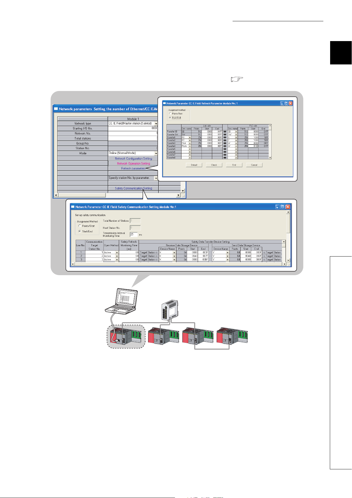
CHAPTER 7 PARAMETER SETTING 77
7.1 Parameter List . . . . . . . . . . . . . . . . . . . . . . . . . . . . . . . . . . . . . . . . . . . . . . . . . . . . . . . . . . . . . 77
7.2 Network Setting . . . . . . . . . . . . . . . . . . . . . . . . . . . . . . . . . . . . . . . . . . . . . . . . . . . . . . . . . . . . 79
7.3 Network Configuration Setting . . . . . . . . . . . . . . . . . . . . . . . . . . . . . . . . . . . . . . . . . . . . . . . . . 81
7.4 Network Operation Setting . . . . . . . . . . . . . . . . . . . . . . . . . . . . . . . . . . . . . . . . . . . . . . . . . . . . 85
7.5 Refresh Parameters . . . . . . . . . . . . . . . . . . . . . . . . . . . . . . . . . . . . . . . . . . . . . . . . . . . . . . . . . 86
7.6 Safety Communication Setting . . . . . . . . . . . . . . . . . . . . . . . . . . . . . . . . . . . . . . . . . . . . . . . . . 90
7.7 Routing Parameters . . . . . . . . . . . . . . . . . . . . . . . . . . . . . . . . . . . . . . . . . . . . . . . . . . . . . . . . . 92
CHAPTER 8 FUNCTIONS 96
8.1 Safety Communication Function. . . . . . . . . . . . . . . . . . . . . . . . . . . . . . . . . . . . . . . . . . . . . . . . 96
8.1.1 Communication with safety stations. . . . . . . . . . . . . . . . . . . . . . . . . . . . . . . . . . . . . . . . . . . . 96
8.1.2 Error log registration function . . . . . . . . . . . . . . . . . . . . . . . . . . . . . . . . . . . . . . . . . . . . . . . . . 99
8.1.3 Safety station interlock function . . . . . . . . . . . . . . . . . . . . . . . . . . . . . . . . . . . . . . . . . . . . . . 100
8.2 Cyclic Transmission . . . . . . . . . . . . . . . . . . . . . . . . . . . . . . . . . . . . . . . . . . . . . . . . . . . . . . . . 102
8.2.1 Data flow and link device assignment . . . . . . . . . . . . . . . . . . . . . . . . . . . . . . . . . . . . . . . . . 103
8.2.2 Link refresh . . . . . . . . . . . . . . . . . . . . . . . . . . . . . . . . . . . . . . . . . . . . . . . . . . . . . . . . . . . . . 104
8.2.3 Assurance of cyclic data integrity. . . . . . . . . . . . . . . . . . . . . . . . . . . . . . . . . . . . . . . . . . . . . 106
8.2.4 Scan synchronization specification . . . . . . . . . . . . . . . . . . . . . . . . . . . . . . . . . . . . . . . . . . . 112
8.2.5 Input status setting in case of failure. . . . . . . . . . . . . . . . . . . . . . . . . . . . . . . . . . . . . . . . . . 113
8.2.6 Output status setting for CPU module STOP. . . . . . . . . . . . . . . . . . . . . . . . . . . . . . . . . . . . 115
8.2.7 Cyclic transmission stop and restart . . . . . . . . . . . . . . . . . . . . . . . . . . . . . . . . . . . . . . . . . . 116
8.3 Transient Transmission. . . . . . . . . . . . . . . . . . . . . . . . . . . . . . . . . . . . . . . . . . . . . . . . . . . . . .117
8.3.1 Communication within the same network. . . . . . . . . . . . . . . . . . . . . . . . . . . . . . . . . . . . . . . 117
8.3.2 Communication with different networks . . . . . . . . . . . . . . . . . . . . . . . . . . . . . . . . . . . . . . . . 118
8.4 Reserved station specification and reserved station function disable . . . . . . . . . . . . . . . . . .119
8.5 Error Invalid Station and Temporary Error Invalid Station Setting Function . . . . . . . . . . . . . .120
8.6 Loopback Function . . . . . . . . . . . . . . . . . . . . . . . . . . . . . . . . . . . . . . . . . . . . . . . . . . . . . . . . .121
CHAPTER 9 CC-Link IE FIELD NETWORK DIAGNOSTICS 124
9.1 Diagnostic Items. . . . . . . . . . . . . . . . . . . . . . . . . . . . . . . . . . . . . . . . . . . . . . . . . . . . . . . . . . .124
9.2 Starting Diagnostics . . . . . . . . . . . . . . . . . . . . . . . . . . . . . . . . . . . . . . . . . . . . . . . . . . . . . . . .127
9.3 Diagnostic Window. . . . . . . . . . . . . . . . . . . . . . . . . . . . . . . . . . . . . . . . . . . . . . . . . . . . . . . . .130
9.4 Link Start/Stop. . . . . . . . . . . . . . . . . . . . . . . . . . . . . . . . . . . . . . . . . . . . . . . . . . . . . . . . . . . . .138
9.5 Network Event History . . . . . . . . . . . . . . . . . . . . . . . . . . . . . . . . . . . . . . . . . . . . . . . . . . . . . .140
9.6 Canceling/Restoring Reserved Station Setting . . . . . . . . . . . . . . . . . . . . . . . . . . . . . . . . . . . .142
9.7 Setting/Canceling Temporary Error Invalid Station . . . . . . . . . . . . . . . . . . . . . . . . . . . . . . . . .146
9.8 Remote Operation . . . . . . . . . . . . . . . . . . . . . . . . . . . . . . . . . . . . . . . . . . . . . . . . . . . . . . . . . 151
CHAPTER 10 DEDICATED INSTRUCTIONS 152
10.1 List of Dedicated Instructions . . . . . . . . . . . . . . . . . . . . . . . . . . . . . . . . . . . . . . . . . . . . . . . . .152
10.2 Precautions for Dedicated Instructions . . . . . . . . . . . . . . . . . . . . . . . . . . . . . . . . . . . . . . . . . .155
10.2.1 Precautions for link dedicated instructions. . . . . . . . . . . . . . . . . . . . . . . . . . . . . . . . . . . . . . 155
11
Page 14

10.3 Understanding the Documentation on Dedicated Instructions . . . . . . . . . . . . . . . . . . . . . . . . 158
10.4 JP/GP.READ (Reading Data from the Programmable Controller on Another Station) . . . . . .160
10.5 JP/GP.SREAD (Reading Data from the Programmable Controller on Another Station) . . . . . 168
10.6 JP/GP.WRITE (Writing Data to the Programmable Controller on Another Station) . . . . . . . .175
10.7 JP/GP.SWRITE (Writing Data to the Programmable Controller on Another Station) . . . . . . .187
10.8 JP/GP.REQ (Reading/Writing Clock Data) . . . . . . . . . . . . . . . . . . . . . . . . . . . . . . . . . . . . . . .194
CHAPTER 11 PROGRAMMING 209
11.1 Precautions for Programming . . . . . . . . . . . . . . . . . . . . . . . . . . . . . . . . . . . . . . . . . . . . . . . . .209
11.2 Communication Example of when Safety Stations and a Standard Station are Used . . . . . .211
11.2.1 System configuration example . . . . . . . . . . . . . . . . . . . . . . . . . . . . . . . . . . . . . . . . . . . . . . . 211
11.2.2 Master station (standard station) settings . . . . . . . . . . . . . . . . . . . . . . . . . . . . . . . . . . . . . . 213
11.2.3 Local station (safety station) settings . . . . . . . . . . . . . . . . . . . . . . . . . . . . . . . . . . . . . . . . . . 215
11.2.4 Checking the network status . . . . . . . . . . . . . . . . . . . . . . . . . . . . . . . . . . . . . . . . . . . . . . . . 218
11.2.5 Program example. . . . . . . . . . . . . . . . . . . . . . . . . . . . . . . . . . . . . . . . . . . . . . . . . . . . . . . . . 219
11.3 Using Link Special Relay (SB) and Link Special Register (SW) . . . . . . . . . . . . . . . . . . . . . . . 221
CHAPTER 12 TROUBLESHOOTING 235
12.1 Before Troubleshooting . . . . . . . . . . . . . . . . . . . . . . . . . . . . . . . . . . . . . . . . . . . . . . . . . . . . .235
12.2 Troubleshooting Procedure . . . . . . . . . . . . . . . . . . . . . . . . . . . . . . . . . . . . . . . . . . . . . . . . . .235
12.3 Checking the LEDs . . . . . . . . . . . . . . . . . . . . . . . . . . . . . . . . . . . . . . . . . . . . . . . . . . . . . . . . .239
12.4 Troubleshooting by Symptom . . . . . . . . . . . . . . . . . . . . . . . . . . . . . . . . . . . . . . . . . . . . . . . . .242
12.4.1 Safety communication cannot be established . . . . . . . . . . . . . . . . . . . . . . . . . . . . . . . . . . . 242
12.4.2 Cyclic transmission cannot be performed . . . . . . . . . . . . . . . . . . . . . . . . . . . . . . . . . . . . . . 243
12.4.3 Transient transmission cannot be performed. . . . . . . . . . . . . . . . . . . . . . . . . . . . . . . . . . . . 244
12.4.4 Station is disconnected from the network. . . . . . . . . . . . . . . . . . . . . . . . . . . . . . . . . . . . . . . 244
12.4.5 Station is repeatedly disconnected and reconnected . . . . . . . . . . . . . . . . . . . . . . . . . . . . . 245
12.4.6 Communication is unstable . . . . . . . . . . . . . . . . . . . . . . . . . . . . . . . . . . . . . . . . . . . . . . . . . 245
12.5 Error Code List . . . . . . . . . . . . . . . . . . . . . . . . . . . . . . . . . . . . . . . . . . . . . . . . . . . . . . . . . . . .246
12.6 Checking the Master/Local Module Status by System Monitor. . . . . . . . . . . . . . . . . . . . . . . .261
APPENDICES 264
Appendix 1 Details of I/O Signals. . . . . . . . . . . . . . . . . . . . . . . . . . . . . . . . . . . . . . . . . . . . . . . . . . .264
Appendix 1.1 Module failure (X0) . . . . . . . . . . . . . . . . . . . . . . . . . . . . . . . . . . . . . . . . . . 264
Appendix 1.2 Own station data link status (X1) . . . . . . . . . . . . . . . . . . . . . . . . . . . . . . . . . 264
Appendix 1.3 Other stations data link status (X3) . . . . . . . . . . . . . . . . . . . . . . . . . . . . . . . 265
Appendix 1.4 Module ready (XF) . . . . . . . . . . . . . . . . . . . . . . . . . . . . . . . . . . . . . . . . . . 265
Appendix 2 Details of Buffer Memory Addresses. . . . . . . . . . . . . . . . . . . . . . . . . . . . . . . . . . . . . . . 266
Appendix 2.1 Link device area (buffer memory address: 0 to 18975 (0H to 4A1FH)) . . . . . . . . . 266
Appendix 2.2 RX offset/size information (buffer memory address: 19456 to 19695 (4C00H to 4CEFH))
. . . . . . . . . . . . . . . . . . . . . . . . . . . . . . . . . . . . . . . . . . . . . . . . . . . . . . . 269
Appendix 2.3 RY offset/size information (buffer memory address: 19712 to 19951 (4D00H to 4DEFH))
. . . . . . . . . . . . . . . . . . . . . . . . . . . . . . . . . . . . . . . . . . . . . . . . . . . . . . . 269
Appendix 2.4 RWw offset/size information (buffer memory address: 19968 to 20207 (4E00H to
)) . . . . . . . . . . . . . . . . . . . . . . . . . . . . . . . . . . . . . . . . . . . . . . . . . 270
4EEF
H
12
Page 15

Appendix 2.5 RWr offset/size information (buffer memory address: 20224 to 20463 (4F00H to
)) . . . . . . . . . . . . . . . . . . . . . . . . . . . . . . . . . . . . . . . . . . . . . . . . . 270
4FEF
H
Appendix 2.6 Own station information (buffer memory address: 20512 to 20536 (5020H to 5038H))
. . . . . . . . . . . . . . . . . . . . . . . . . . . . . . . . . . . . . . . . . . . . . . . . . . . . . . . 271
Appendix 2.7 Other station information (buffer memory address: 20544 to 24383 (5040H to 5F3FH))
. . . . . . . . . . . . . . . . . . . . . . . . . . . . . . . . . . . . . . . . . . . . . . . . . . . . . . . 272
Appendix 3 Link Special Relay (SB) List . . . . . . . . . . . . . . . . . . . . . . . . . . . . . . . . . . . . . . . . . . . . .273
Appendix 4 Link Special Register (SW) List. . . . . . . . . . . . . . . . . . . . . . . . . . . . . . . . . . . . . . . . . . . 286
Appendix 5 Processing Time . . . . . . . . . . . . . . . . . . . . . . . . . . . . . . . . . . . . . . . . . . . . . . . . . . . . . .302
Appendix 5.1 Link refresh time . . . . . . . . . . . . . . . . . . . . . . . . . . . . . . . . . . . . . . . . . . . 302
Appendix 5.2 Link scan time . . . . . . . . . . . . . . . . . . . . . . . . . . . . . . . . . . . . . . . . . . . . . 303
Appendix 5.3 Cyclic transmission delay time . . . . . . . . . . . . . . . . . . . . . . . . . . . . . . . . . . 304
Appendix 5.4 Transmission interval monitoring time . . . . . . . . . . . . . . . . . . . . . . . . . . . . . 308
Appendix 5.5 Safety refresh monitoring time . . . . . . . . . . . . . . . . . . . . . . . . . . . . . . . . . . 309
Appendix 5.6 Transmission delay time of dedicated instructions . . . . . . . . . . . . . . . . . . . . . 310
Appendix 6 New and Improved Functions . . . . . . . . . . . . . . . . . . . . . . . . . . . . . . . . . . . . . . . . . . . .312
Appendix 7 Comparison with an Existing Product . . . . . . . . . . . . . . . . . . . . . . . . . . . . . . . . . . . . . .313
Appendix 7.1 Comparison between the CC-Link Safety master module and the master/local
. . . . . . . . . . . . . . . . . . . . . . . . . . . . . . . . . . . . . . . . . . . . . . . . . . 313
module
Appendix 7.2 Comparison between the Q series master/local module and the master/local module
. . . . . . . . . . . . . . . . . . . . . . . . . . . . . . . . . . . . . . . . . . . . . . . . . . . . . . . 317
Appendix 8 Precautions for When Connecting the MELSEC iQ-R Series Module . . . . . . . . . . . . .320
Appendix 9 Checking the Serial Number and Function Version . . . . . . . . . . . . . . . . . . . . . . . . . . .321
Appendix 10 External Dimension Diagram . . . . . . . . . . . . . . . . . . . . . . . . . . . . . . . . . . . . . . . . . . . .323
INDEX 325
REVISIONS . . . . . . . . . . . . . . . . . . . . . . . . . . . . . . . . . . . . . . . . . . . . . . . . . . . . . . . . . . . . . . . . . . . . . . 328
WARRANTY . . . . . . . . . . . . . . . . . . . . . . . . . . . . . . . . . . . . . . . . . . . . . . . . . . . . . . . . . . . . . . . . . . . . . 329
13
Page 16
MANUAL PAGE ORGANIZATION
The section of
the current page is shown.
The chapter of
the current page is shown.
"" is used for
window names and items.
[ ] is used for items
in the menu bar and
the project window.
shows operating
procedures.
shows reference
manuals.
shows notes that
require attention.
shows mouse
operations.
*1
shows
reference pages.
shows setting or
operating examples.
Ex.
shows useful
information.
[Online] [Write to PLC...]
Select [Online] on the menu bar,
and then select [Write to PLC...].
Menu bar
Ex.
Ex.
[PLC parameter]
In the Project data list, expand [Parameter] and
select [PLC parameter].
Project data list
Project data list [Parameter]
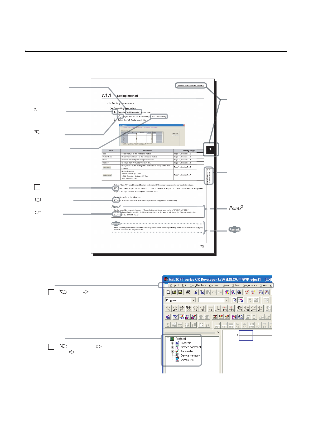
In this manual, pages are organized and the symbols are used as shown below.
The following illustration is for explanation purpose only, and should not be referred to as an actual documentation.
14
*1 The mouse operation example is provided below.
Page 17

TERM
Unless otherwise specified, this manual uses the following terms.
Ter m Description
Safety programmable controller
Standard programmable controller
QSCPU Another term for the MELSEC-QS series CPU module
LCPU Another term for the MELSEC-L series CPU module
QCPU Another term for the MELSEC-Q series CPU module
QnACPU Another term for the MELSEC-QnA series CPU module
ACPU Another term for the MELSEC-A series CPU module
System A CPU A CPU module where the system A connector of a tracking cable is connected in a redundant system
System B CPU A CPU module where the system B connector of a tracking cable is connected in a redundant system
Control system CPU A CPU module that controls operations in a redundant system
Standby system CPU A CPU module that stands by in case the control system fails in a redundant system
Control CPU
Programming tool A generic term for GX Works2 and GX Developer
GX Developer
GX Works2
CC-Link IE Field Network A high-speed and large-capacity open field network that is based on Ethernet (1000BASE-T)
CC-Link
Safety CPU module The abbreviation for the QS001CPU safety CPU module
Master/local module
Q series master/local module The abbreviation for the QJ71GF11-T2 CC-Link IE Field Network master/local module
L series master/local module The abbreviation for the LJ71GF11-T2 CC-Link IE Field Network master/local module
CC-Link Safety master module The abbreviation for the QS0J61BT12 CC-Link Safety system master module
Head module The abbreviation for the LJ72GF15-T2 CC-Link IE Field Network head module
Ethernet adapter module The abbreviation for the NZ2GF-ETB CC-Link IE Field Network Ethernet adapter module
CC-Link IE Field Network interface board The abbreviation for the Q81BD-J71GF11-T2 CC-Link IE Field Network interface board
Network module
Intelligent function module
Safety data Data exchanged through safety communication
Safety connection A connection established for safety communication
Safety communication A function to exchange safety data between safety stations on the same network
Standard communication A generic term for cyclic transmission and transient transmission
Cyclic transmission
Transient transmission
Safety station A generic term for a station that performs safety communication and standard communication
Standard station A generic term for a station that performs standard communication
A generic term for a safety CPU module, a safety power supply module, a safety main base unit, a CC-Link Safety
master module, CC-Link Safety remote I/O modules, and a master/local module
A generic term for MELSEC-Q series, MELSEC-L series, MELSEC-QnA series, MELSEC-A series, and MELSECFX series modules (This term is used to distinguish a programmable controller that uses these modules from a
safety programmable controller.)
A CPU module that controls connected I/O modules and intelligent function modules. In a multiple CPU system,
there are multiple CPU modules and each connected module can be controlled by a different CPU module.
The product name of the software package for the MELSEC programmable controllers
A field network system where data processing for control and information can be simultaneously performed at high
speed
The abbreviation for the QS0J71GF11-T2 CC-Link IE Field Network master/local module. This module supports
safety functions.
A generic term for the following modules:
• Module on CC-Link IE Field Network
• CC-Link IE Controller Network module
• Ethernet interface module
• MELSECNET/H module
• MELSECNET/10 module
A MELSEC-Q/L series module that has functions other than input and output, such as an A/D converter module
and D/A converter module
A function by which data are periodically exchanged among stations on the same network using link devices (RX,
RY, RWw, and RWr)
A function of communication with another station, which is used when requested by a dedicated instruction
or a programming tool
15
Page 18
Term Description
A station that controls the entire network. Only one master station can be used in a network.
This station serves as a safety station or a standard station, and can perform cyclic transmission and transient
Master station
Local station
Remote I/O station A station that exchanges I/O signals (bit data) with the master station by cyclic transmission
Remote device station
Intelligent device station
Slave station A generic term for a local station, remote I/O station, remote device station, and intelligent device station
Reserved station A station reserved for future use. This station is not actually connected, but counted as a connected station.
Relay station
Data link Generic term for cyclic transmission and transient transmission
Seamless communication
Routing
Dedicated instruction An instruction that simplifies programming for using functions of intelligent function modules
Link dedicated instruction
Return Processing that restarts data link when a station recovers from an error
Disconnection Processing that stops data link if a data link error occurs
Loopback
Device A device (X, Y, M, D, or others) in a CPU module
Link device A device (RX, RY, RWr, or RWw) in a module on CC-Link IE Field Network
Remote input (RX)
Remote output (RY)
Remote register (RWr)
Remote register (RWw)
Link special relay (SB) Bit data that indicates the operating status and data link status of a module on CC-Link IE Field Network
Link special register (SW) Word data that indicates the operating status and data link status of a module on CC-Link IE Field Network
Link scan (Link scan time)
Link refresh
Baton pass A token to send data over a network
Buffer memory
transmission with all stations.
When set as a safety station, the station can perform safety communication with another safety station on the
same network.
A station that serves as a safety station or a standard station. This station can perform cyclic transmission and
transient transmission with the master station and other local stations.
When set as a safety station, the station can perform safety communication with another safety station on the
same network. The station is controlled by programs in the CPU module or other equivalent modules on the
station.
A station that exchanges I/O signals (bit data) and I/O data (word data) with another station by cyclic transmission.
This station responds to a transient transmission request from another station.
A station that exchanges I/O signals (bit data) and I/O data (word data) with another station by cyclic transmission.
This station responds to a transient transmission request from another station and also issues a transient
transmission request to another station.
A station that includes two or more network modules. Data are passed through this station to stations on other
networks.
Communication that allows users to access a different kind of networks without having to consider the differences
as if data were exchanged within one single network.
A process of selecting paths for communication with other networks.
CC-Link IE Field Network requires communication paths to be preset using routing parameters to communicate
with stations on different networks.
A dedicated instruction used for transient transmission with a programmable controller on another station.
This instruction allows a master/local module to communicate with programmable controllers on the same network
(CC-Link IE Field Network) and on other networks (Ethernet, CC-Link IE Controller Network, and MELSECNET/H).
A function that disconnects the station in which an error has occurred, and continues data link with the stations that
are operating normally. Stations connected after the faulty station can also continue data link.
Bit data input from a slave station to the master station (For some areas in a local station, data are input in the
opposite direction.)
Page 103, Section 8.2.1
Bit data output from the master station to a slave station (For some areas in a local station, data are output in the
opposite direction.)
Page 103, Section 8.2.1
Word data input from a slave station to the master station (For some areas in a local station, data are input in the
opposite direction.)
Page 103, Section 8.2.1
Word data output from the master station to a slave station (For some areas in a local station, data are output in the
opposite direction.)
Page 103, Section 8.2.1
Time required for all the stations on the network to transmit data. The link scan time depends on data volume and
the number of transient transmission requests.
Data transfer between a link device in a module on CC-Link IE Field Network and a device in a CPU module. Link
refresh is performed in the END processing of the CPU module's sequence scan.
A memory in an intelligent function module, where data (such as setting values and monitoring values) exchanged
with a CPU module are stored
16
Page 19

Ter m Description
Buffer memory address
RAS
READ The abbreviation for JP.READ and GP.READ
SREAD The abbreviation for JP.SREAD and GP.SREAD
WRITE The abbreviation for JP.WRITE and GP.WRITE
SWRITE The abbreviation for JP.SWRITE and GP.SWRITE
REQ The abbreviation for JP.REQ and GP.REQ
An address that indicates the storage location of data assigned to the buffer memory in an intelligent function
module
The abbreviation for Reliability, Availability, and Serviceability. This term refers to usability of automated
equipment.
17
Page 20
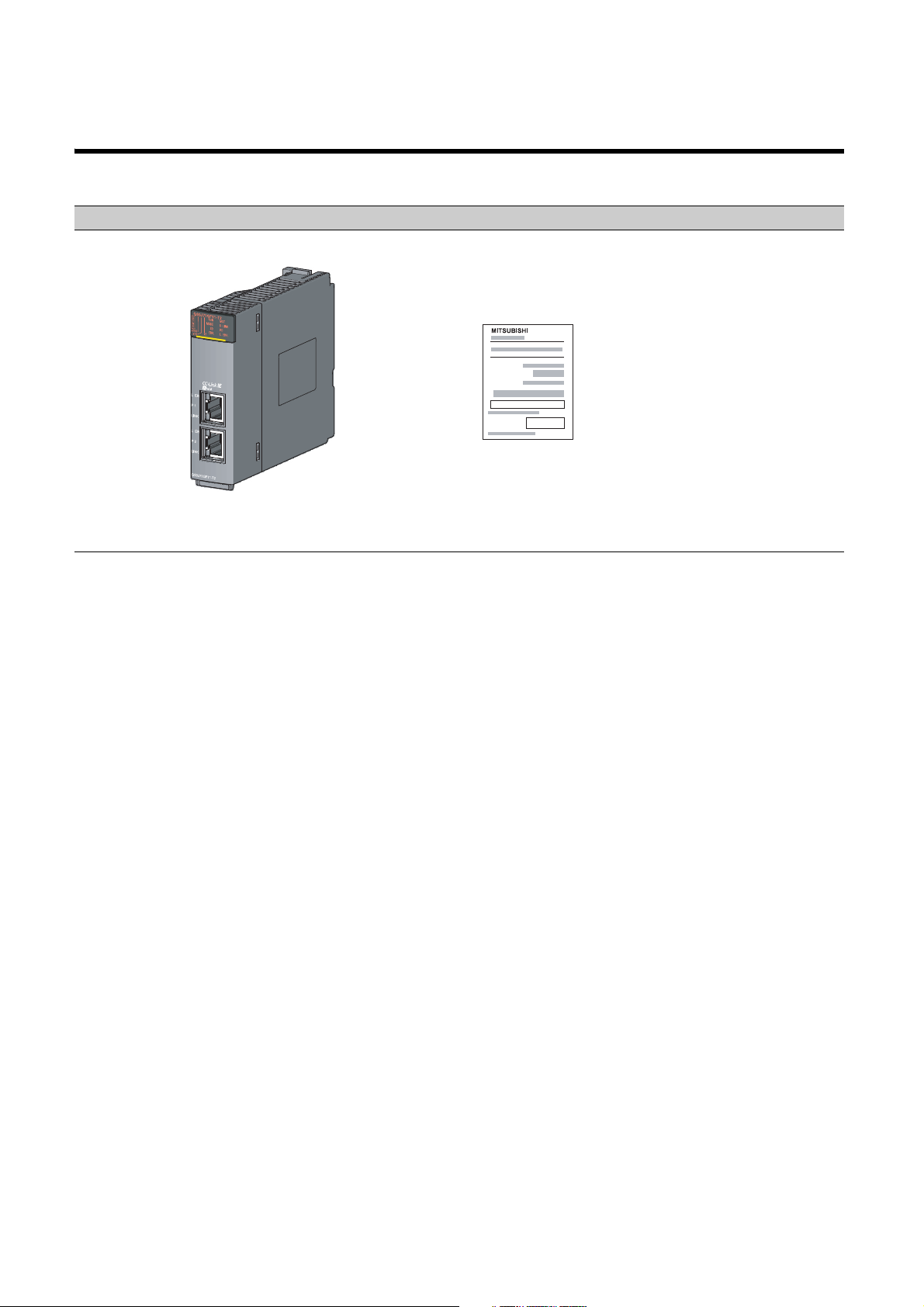
PACKING LIST
QS0J71GF11-T2
MELSEC-QS CC-Link IE Field Network
Master/Local Module
User's Manual (Hardware)
The following items are included in the package of this product. Before use, check that all the items are included.
QS0J71GF11-T2
18
Page 21
CHAPTER 1 CC-Link IE FIELD NETWORK
Master
station
(safety station)
Local
station
(safety station)
Safety CPU
module
Device
Device
Safety CPU
module
Device
Device
Master station
(safety station)
Local station
(safety station)
1) Safety connection
establishment
2) Safety data transfer
3) Safety data transfer
After safety connection
is established, data
is communicated.
CHAPTER 1 CC-Link IE FIELD NETWORK
1.1 CC-Link IE Field Network
CC-Link IE Field Network is a high-speed and large-capacity open field network that is based on Ethernet
(1000BASE-T).
(1) Data communication
High-speed and large-capacity data communication is available between a master station and slave stations on
CC-Link IE Field Network. A safety station can operate safety communication and standard communication
simultaneously.
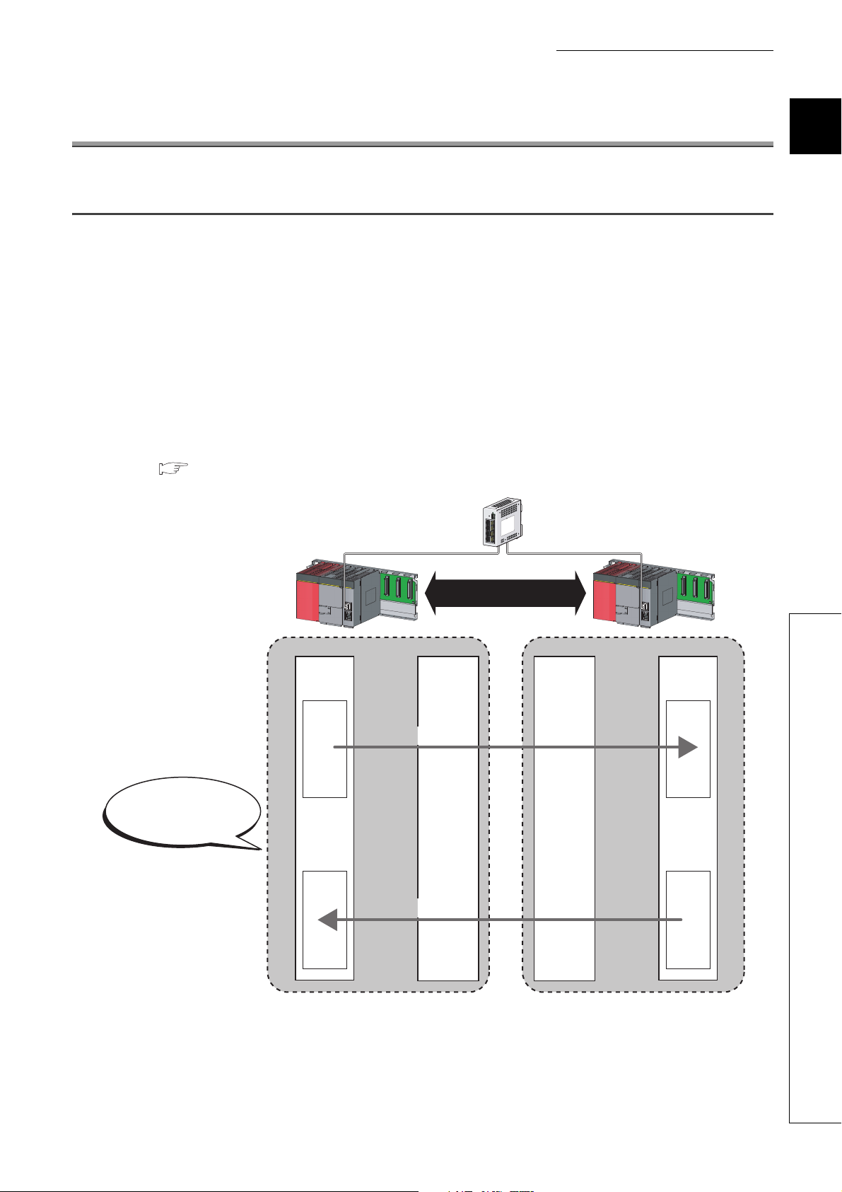
(a) Safety communication
Data communication ensuring high safety (safety communication) can be performed.
Data is communicated after a safety connection is established between safety stations on the same network.
( Page 96, Section 8.1)
1
1.1 CC-Link IE Field Network
19
Page 22
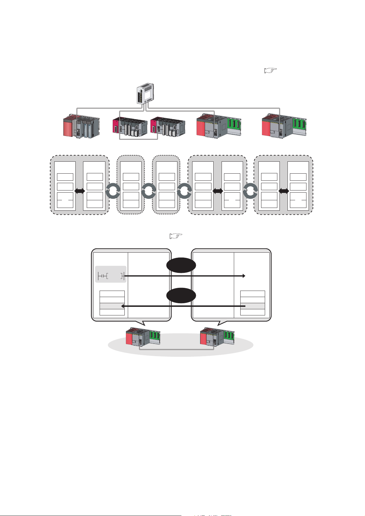
(b) Standard communication
Master
station
(standard station)
CPU module
X
Y
W
RX
RY
RWw
RWr
Local station
(safety station)
Safety
CPU module
Y
X
W
RY
RX
RWr
RWw
RX
RY
RWw
RWr
RX
RY
RWw
RWr
Intelligent
device station
Intelligent
device station
Master station
(standard station)
Local station
(safety station)
Local station
(safety station)
Safety
CPU module
Y
X
W
RY
RX
RWr
RWw
Local station
(safety station)
Intelligent
device station
Intelligent
device station
• Periodic communication (cyclic transmission)
Data is periodically communicated among stations within the same network. ( Page 102, Section 8.2)
• Non-periodic communication (transient transmission)
Data is communicated upon request. ( Page 117, Section 8.3)
Safety
CPU module
Command
Instruction
Device
1234
H
Master station
(safety station)
Read
request
Response
data
Local station
(safety station)
Safety
CPU module
Device
1234
H
20
Page 23

CHAPTER 1 CC-Link IE FIELD NETWORK
Line topology Line topology Line topology
Star topology
(2) 1Gbps communication speed
1Gbps communication speed allows high-speed communication. Also, the takt time can be reduced due to the
improved performance of communication response.
(3) Use of Ethernet cable
A 1000BASE-T-compliant Ethernet is used for the connection interface. The wiring cost can be reduced because
1000BASE-T-compliant Ethernet cables are commercially available. ( Page 56, Section 5.2)
1000BASE-T
(4) Flexible wiring for system arrangements
The network can be wired into star topology, line topology, and ring topology. ( Page 47, Section 5.1.1)
For star topology, a 1000BASE-T compliant switching hub can be used. ( Page 57, Section 5.2.2)
Wiring is highly flexible because a network can consist of a combination of star and line topologies. For example,
the control panels can be connected through a star topology and the production lines through a line topology.
1
1.1 CC-Link IE Field Network
21
Page 24
1.2 Master/Local Modules
Adding a
station
Adding a
station
Safety
station
Safety
station
Standard
station
Standard
station
Safety communication
A master/local module is used to connect a safety programmable controller to CC-Link IE Field Network.
The module is used being mounted on a safety base unit.
The module can be used as the following stations on CC-Link IE Field Network.
• Master station (safety station)
• Local station (safety station)
• Local station (standard station)
(1) Communication that ensures safety (safety communication)
Data communication ensuring high safety (safety communication) can be performed.
Data is communicated after a safety connection is established between safety stations on the same network.
( Page 96, Section 8.1)
(a) Safety stations added on CC-Link IE Field Network
Safety programmable controllers and standard programmable controllers can co-exist on the same network. A
network system with high safety can be easily established by adding safety stations on an existing CC-Link IE
Field Network. ( Page 47, Section 5.1.1)
22
The master/local module has acquired certification of the highest safety level (SIL3 of IEC 61508, Category 4 of EN 654-1,
and Category 4 performance level
"e" of EN ISO 13849-1) applicable to programmable controllers.
Page 25
CHAPTER 1 CC-Link IE FIELD NETWORK
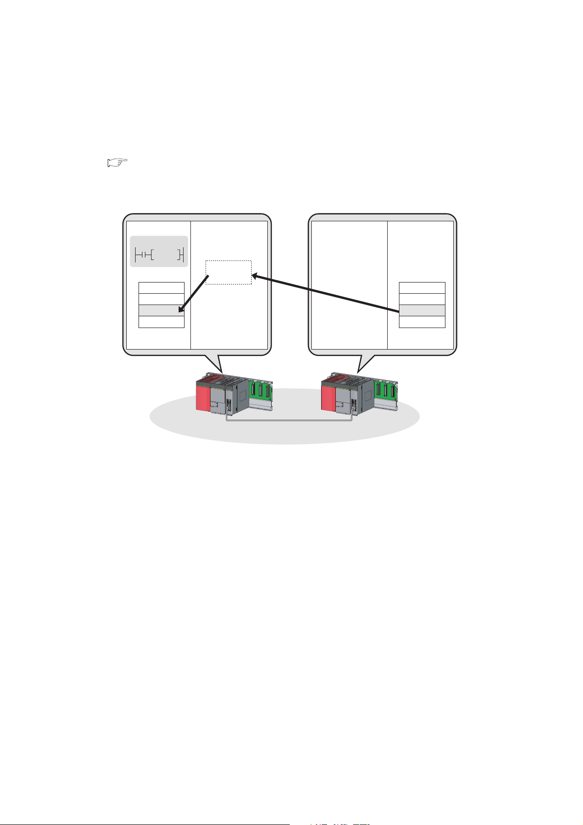
(2) High-speed periodic communication (cyclic transmission)
Since transmission delay time is short, delay caused by the network does not need to be considered (if the link
scan time of each master/local module is shorter than the scan time of the safety CPU module).
Command
High speed
Master/local modules can perform cyclic transmissions in combination with the following functions:
( Page 35, Section 3.3)
• Auto transfer of data between the link devices in the master/local module and the devices in the safety CPU
module
• Cyclic data assurance in units of 32 bits or per station
• Status setting (hold or clear) of input data of standard communication to which a data link error has occurred
• Station reservation for future connection, and others
1
1.2 Master/Local Modules
23
Page 26
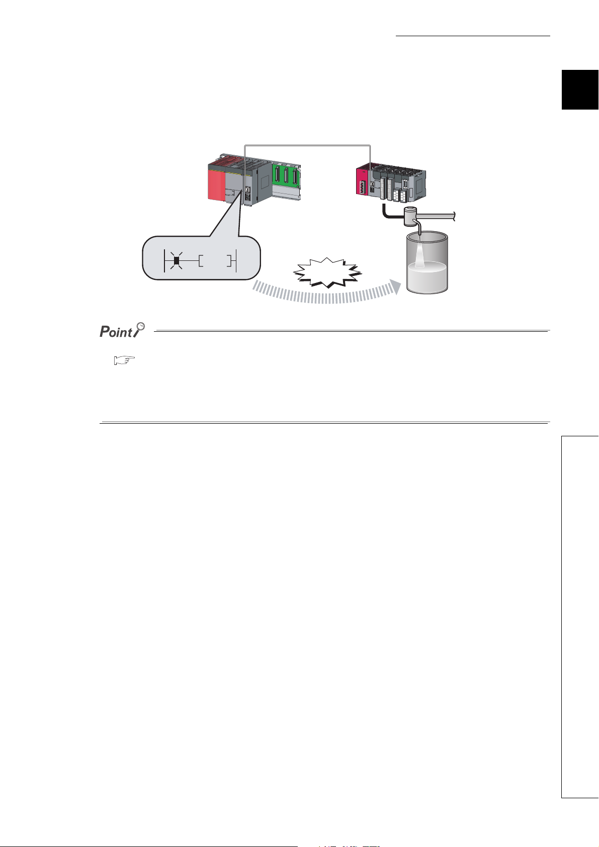
(3) Non-periodic communication (transient transmission) with programmable
Command
READ
Device Device
1234
H
1234
H
Safety CPU module Safety CPU module
Master station
(safety station)
Local station
(safety station)
controllers on other stations
(a) Reading or writing data
A master/local module can access programmable controllers on other stations by dedicated instructions.
( Page 152, Section 10.1)
Seamless access of programmable controllers on other networks such as Ethernet, CC-Link IE Controller
Network, MELSECNET/H, and MELSECNET/10 is also possible.
24
Page 27
CHAPTER 1 CC-Link IE FIELD NETWORK
(4) Settings and diagnostics by GX Developer
(a) Setting parameters
Parameters for master/local modules can be set using GX Developer. ( Page 77, CHAPTER 7)
1
1.2 Master/Local Modules
25
Page 28
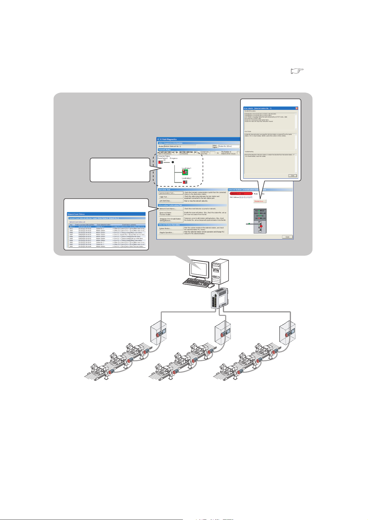
(b) Checking CC-Link IE Field Network status graphically
Displays error details
Displays the network event history
Displays the status of
CC-Link IE Field Network
CC-Link IE Field Network status can be checked using GX Developer. Error locations, error causes, and event
history are displayed on the window. This allows the system to quickly recover from errors. ( Page 124,
CHAPTER 9)
26
Page 29
CHAPTER 1 CC-Link IE FIELD NETWORK
GX Developer
CC-Link IE Field Network
CC-Link IE Controller Network
Network No. 2
Network No. 1
(Relay station)
Seamless
access
Systems on other networks
can be tested or monitored.
(c) Seamless access to other networks
GX Developer can seamlessly access (test or monitor) systems composed of CC-Link IE Field Network and
other networks. The accessible networks are Ethernet, CC-Link IE Controller Network, MELSECNET/H,
MELSECNET/10, and CC-Link.
Seamless access enables the user to change the access target without modifying the connection between the
personal computer and programmable controller.
For details on access range, refer to the following.
QSCPU User’s Manual (Function Explanation, Program Fundamentals)
1
1.2 Master/Local Modules
27
Page 30
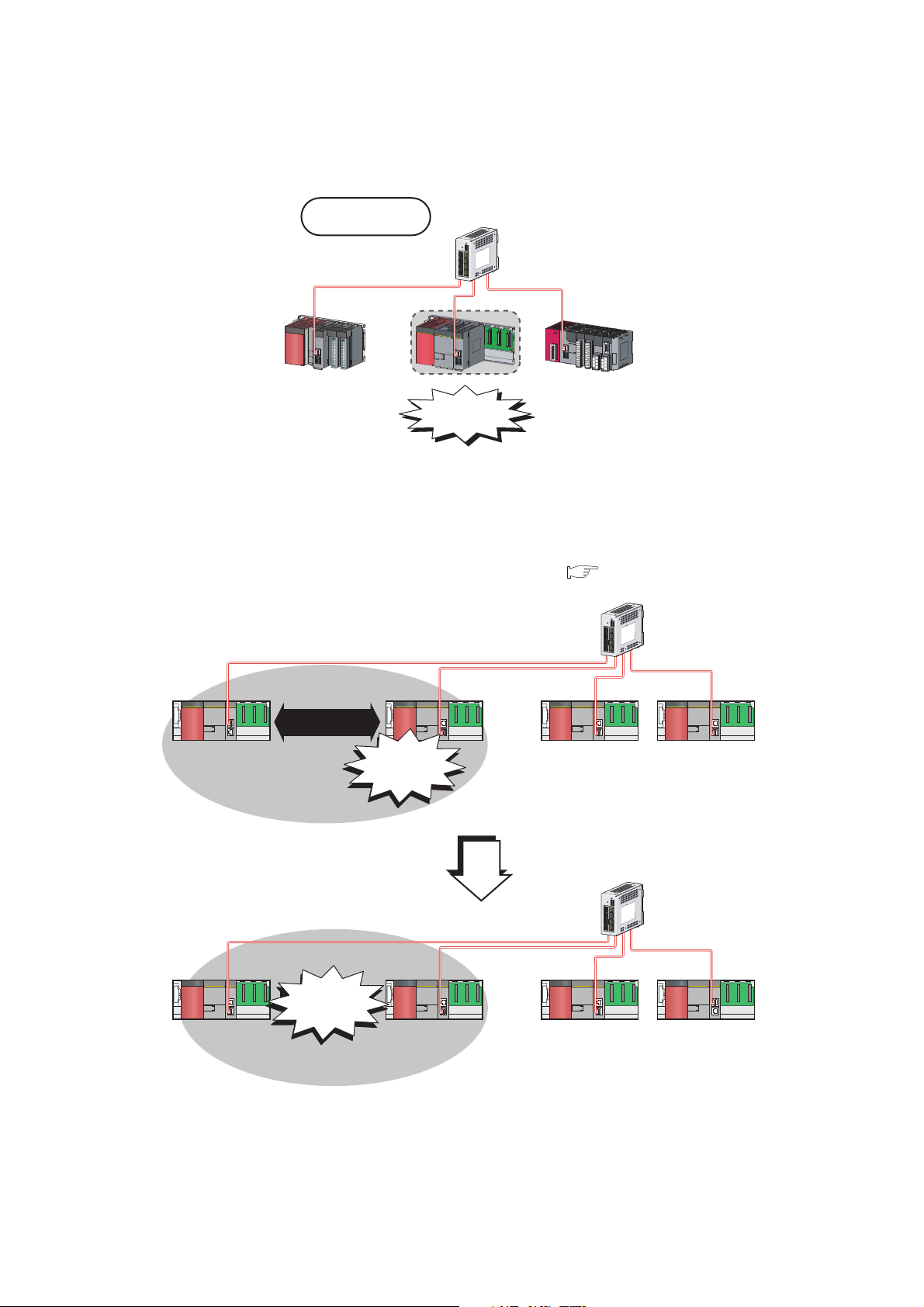
(5) Replacing CC-Link IE Field Network devices without stopping the system
Master station
(safety station)
Station No. 0
Local station
(standard station)
Station No. 1
Local station
(safety station)
Station No. 3
Local station
(standard station)
Station No. 2
Error
Master station
(safety station)
Station No. 0
Local station
(standard station)
Station No. 1
Local station
(safety station)
Station No. 3
Local station
(standard station)
Station No. 2
Communication
disconnection
and interlock
Safety
communication
For star topology, slave stations can be replaced without powering off the whole system.
Star topology
Replacement
(6) RAS function when a communication error occurs
(a) During safety communication
When a communication error occurs between safety stations, communication is automatically disconnected in
order to prevent incorrect input/output from/to the faulty station. ( Page 100, Section 8.1.3)
28
Page 31

CHAPTER 1 CC-Link IE FIELD NETWORK
Master station
(safety station)
Station No. 0
Local station
(standard station)
Station No. 1
Local station
(safety station)
Station No. 3
Local station
(standard station)
Station No. 2
Disconnection
Master station
(safety station)
Station No. 0
Local station
(standard station)
Station No. 1
Local station
(safety station)
Station No. 3
Local station
(standard station)
Station No. 2
Master station
(safety station)
Station No. 0
Local station
(standard station)
Station No. 1
Local station
(safety station)
Station No. 3
Local station
(standard station)
Station No. 2
Error
Standard
communication
Standard
communication
Communication is
automatically
disconnected.
Reconnection
When
recovered
from fault
(b) During standard communication
When a communication error occurs, communication is automatically disconnected in order to prevent
incorrect input/output from/to the faulty station. When the disconnected station gets back to normal operation, it
automatically returns to the network and resumes data link. ( Page 35, Section 3.3.1)
1
1.2 Master/Local Modules
29
Page 32

CHAPTER 2 PART NAMES
1)
2)
3)
This chapter describes the names of each part of the master/local modules.
No. Name Application
RUN LED Indicates the operating status.
ON Operates normally.
OFF A hardware failure or a watchdog timer error has occurred.
MST LED Indicates the station type.
ON Operates as a master station (safety station).
OFF Operates as a local station.
MODE LED Indicates the mode.
ON In online mode.
Flashing In test mode (The module is performing a hardware test, self-loopback test, or loop test.)
1)
D LINK LED Indicates the status of the data link.
SD LED Displays the sending status of data.
RD LED Displays the reception status of data.
OFF In offline mode. (Data link not performed)
ON Data link in operation (cyclic transmission in progress)
Flashing Data link in operation (cyclic transmission stopped)
OFF Data link not performed (disconnected)
ON Sending data.
OFF Data not sent.
ON Receiving data.
OFF Data not received.
30
Page 33

No. Name Application
Ex.
ERR. LED
ON
Flashing A data link faulty station was detected.
OFF Working normally.
L ERR. LED
1)
ON
OFF
ST.NO. Displays the station number of the master/local module.
Indicates the error status of the master/local module. The description of the errors can be confirmed in CC-
Link IE Field Network diagnostics. ( Page 124, CHAPTER 9)
One of the following errors has occurred:
• A stop error occurs in the safety CPU module.
• An error was detected in all stations.
• Modules with same station number exist on the network.
• A network parameter is corrupted.
• The network parameter does not match the installation status. (Reserved station specification, number of
connected stations, network number etc.)
Indicates the error status of the received data and the circuit. When the L ERR. LED is on, you can check
the L ER LED for "P1" or "P2" to see on which port the error was detected.
The description of the errors can be confirmed in CC-Link IE Field Network diagnostics. ( Page 124,
CHAPTER 9)
This LED automatically turns off when the module has received normal data and loopback is completed in
ring topology.
• The module has received abnormal data.
• The module is performing loopback.
• The module has received normal data.
• The module is not performing loopback.
Displays the station number.
CHAPTER 2 PART NAMES
2
Station No. 15
1
1
ON
100
10
OFF Operates as a master station (safety station). (station No. 0)
PORT1 connector for CC-Link IE Field Network (RJ45 connector)
P1
L ER
LED
2)
LINK
LED
P2
L ER LED
LINK LED
3)
Serial number display Displays the serial number printed on the rating plate.
ON
OFF
ON Linkup in progress.
OFF Linkdown in progress.
Connect an Ethernet cable. ( Page 64, Section 6.3)
There are no restrictions on the connection order of the cables for the "P1" connector and "P2" connector.
• The module has received abnormal data.
• The module is performing loopback.
• The module has received normal data.
• The module is not performing loopback.
PORT2 connector for CC-Link IE Field Network (RJ45 connector)
Connect an Ethernet cable. ( Page 64, Section 6.3)
There are no restrictions on the connection order of the cables for the "P1" connector and "P2" connector.
(Same as the "P1" connector)
4
1
10 5+=15
31
Page 34

Remark
For LED indication when the master/local module is in test mode (when the module performs hardware test, self-loopback
test, or loop test), refer to the following.
● Hardware test: Page 60, Section 6.2.1
● Self-loopback test: Page 62, Section 6.2.2
● Loop test: Page 67, Section 6.4.1
32
Page 35

CHAPTER 3 SPECIFICATIONS
CHAPTER 3 SPECIFICATIONS
This chapter describes the specifications, function list, I/O signal, and buffer memory of the master/local module.
3.1 General Specifications
For the general specifications of the master/local module, refer to the following.
QSCPU User's Manual (Hardware Design and Maintenance and Inspection)
3.2 Performance Specifications
Item Specifications
Master station (safety
Number of connectable
stations per network
Number of connectable safety stations per network 32 stations
Maximum number of networks 239
Maximum number of
safety connections per
station
Number of safety inputs/outputs per safety
connection
Maximum link points per network
Maximum link points per
station
station)
Local station (standard
station)
Asynchronous mode 31 connections
Synchronous mode 8 connections
Input 8 words
Output 8 words
RX 16384 points, 2KB
RY 16384 points, 2KB
RWr 8192 points, 16KB
RWw 8192 points, 16KB
RX 16384 points, 2KB
Master station
(safety station)
Local station
RY 16384 points, 2KB
RWr 8192 points, 16KB
RWw 8192 points, 16KB
RX 2048 points, 256 bytes
RY 2048 points, 256 bytes
*1
RWr
RWw
1 station
(Up to 120 slave stations can be connected to the master station (safety station).)
120 stations
1024 points, 2048 bytes
1024 points, 2048 bytes
*2
*2
3
3.1 General Specifications
33
Page 36

Item Specifications
Communication speed 1Gbps
Network topology
Connection cable
Maximum station-to-station
Ethernet
Communication method Token passing method
Number of occupied I/O points 32 points (I/O assignment: Intelligent 32 points)
Internal current consumption (5VDC) 0.85A
External dimensions 98(H) × 27.4(W) × 115(D) [mm]
Weight 0.18kg
*1 The maximum number of points for one master station is listed. A local station can receive data from other stations in
*2 256 points and 512 bytes when "Online (High Speed Mode)" is set
distance
Overall cable distance
Number of cascade
connections
addition to this number of points. ( Page 96, Section 8.1.1)
Line topology, star topology (Coexistence of line topology and star topology is
possible.), and ring topology
An Ethernet cable that meets the 1000BASE-T standard: Category 5e or higher
(double shielded, STP), straight cable ( Page 56, Section 5.2.1)
100m max. (Compliant with ANSI/TIA/EIA-568-B (Category 5e))
( Page 66, Section 6.3 (2))
• Line topology: 12000m
(when cables are connected to 1 master station and 120 slave stations)
• Star topology: Depends on the system configuration.
• Ring topology: 12100m
(when cables are connected to 1 master station and 120 slave stations)
Up to 20
34
Page 37

CHAPTER 3 SPECIFICATIONS
3.3 Function List
3.3.1 Using the master/local module as a master station (safety
station)
(1) Safety communication function
Function Description Reference
Communication with safety stations
Error log registration function
Safety station interlock function
Communication starts among safety stations on the same network
after safety connections are established.
Information on errors occurred in safety stations and errors
occurred in communications among safety stations are transferred
to the safety CPU module and registered as error logs.
If an error occurs in safety communication, this function cuts off the
safety communication and prevents automatic resumption of the
communication.
(2) Cyclic transmission
Function Description Reference
Communication
with other
stations
Device and link
device access
Mode selection for cyclic transmission
Assurance of cyclic data integrity
Scan synchronization specification
Input status setting for data link faulty
station
Output status setting for CPU STOP
Cyclic transmission stop and restart
Communication by
RX and RY
Communication by
RWr and RWw
Link refresh
The master station (safety station) communicates I/O data in units
of bits with other stations.
The master station (safety station) communicates I/O data in units
of words with other stations.
Transfer between the link device of the master/local module and the
device of the safety CPU module is performed automatically.
This mode is selected for optimizing the performance of cyclic
transmission based on the cyclic transmission and transient
transmission frequency.
The mode can be selected from "Online (Normal mode)" and
"Online (High-speed mode)".
The cyclic data integrity is assured in units of 32 bits or station-
based units.
Link scan is set to asynchronous or synchronous with the sequence
scan of the safety CPU module.
Select whether the input data from another station where the data
link error occurred is cleared or held.
When the safety CPU module mounted with a master/local module
is set to STOP, whether cyclic data output is held or cleared can be
selected.
During debugging and other operations, cyclic transmission is
stopped. (Data reception from the slave station and data
transmission from own stations are stopped.) Also, the stopped
cyclic transmission is restarted.
Transient transmission is not stopped.
Page 96, Section 8.1.1
Page 99, Section 8.1.2
Page 100, Section 8.1.3
Page 81, Section 7.3
Page 103, Section 8.2.1
Page 86, Section 7.5
Page 104, Section 8.2.2
Page 79, Section 7.2 (1)
Page 106, Section 8.2.3
Page 112, Section 8.2.4
Page 113, Section 8.2.5
Page 115, Section 8.2.6
Page 116, Section 8.2.7
Page 138, Section 9.4
3
3.3 Function List
3.3.1 Using the master/local module as a master station (safety station)
35
Page 38

(3) Transient transmission
Function Description Reference
Communication within the same
network
Communication with different networks
(4) RAS function
Function Description Reference
Slave station disconnection
Automatic return
Loopback function
Transient transmission is performed to other stations using
dedicated instructions and GX Developer.
By setting the routing parameters (communication path) using GX
Developer in advance, transient transmission can be performed to
stations on different networks through dedicated instructions or GX
Developer. Seamless communication is available with the following
networks.
• Ethernet
• CC-Link IE Controller Network
• MELSECNET/H
• MELSECNET/10
• CC-Link (when using GX Developer)
Only the slave station where an error occurs is disconnected, and
data link continues with the stations that are operating normally.
In a line topology, all stations connected after the faulty station are
disconnected.
When the station disconnected from the network due to a data link
failure recovers, it automatically returns to the network and restarts
data link (for standard communication only).
Only the station where an error occurs is disconnected, and data
link continues with the stations that are operating normally.
All stations after the faulty station are disconnected in line topology.
By using the loopback function with ring topology, data link
continues with the stations that are operating normally.
Page 152, CHAPTER 10
Page 92, Section 7.7
Page 118, Section 8.3.2
Page 121, Section 8.6
(5) Diagnostic function
Function Description Reference
CC-Link IE Field Network diagnostics
Individual unit
diagnostics
Own network
diagnostics
Other network
diagnostics
Hardware test Check the internal hardware of the master/local module. Page 60, Section 6.2.1
Self-loopback test
Loop test
Cable test Check the connection status of the Ethernet cable. Page 74, Section 6.4.2
Communication test
The status of CC-Link IE Field Network can be checked by GX
Developer. The faulty area, cause of the fault and its corrective
action, and event history can be checked in GX Developer.
Check the communication circuit of the transmission system of the
master/local module.
Check the network circuit status and parameter setting status of
each station.
Check whether the communication path for transient transmission
from the own station to the target station is correct.
Page 124, CHAPTER 9
Page 62, Section 6.2.2
Page 67, Section 6.4.1
Page 75, Section 6.4.3
36
Page 39

(6) Other functions
Function Description Reference
Reserved station specification
Temporary cancel of the reserved
station setting
Error invalid station and temporary error
invalid station setting
CHAPTER 3 SPECIFICATIONS
The reserved stations are included in the number of stations that
will be connected to the network in the future without actually
connecting them. Reserved stations are not detected as faulty
stations even though they are not actually connected.
Reserved station specification can be temporarily cancelled without
changing the parameters.
Prevent the master station from detecting a slave station as a faulty
station even if the slave station is disconnected during data link.
This can be used when replacing a slave station during data link, for
instance.
Page 119, Section 8.4
Page 142, Section 9.6
3
Page 120, Section 8.5
Page 146, Section 9.7
3.3 Function List
3.3.1 Using the master/local module as a master station (safety station)
37
Page 40

3.3.2 Using the master/local module as a local station
(1) Safety communication function (using the master/local module as a local
station (safety station))
Function Description Reference
Communication with safety stations
Error log registration function
Safety station interlock function
(2) Cyclic transmission
Function Description Reference
Communication
with other
stations
Device and link
device access
Assurance of cyclic data integrity
Input status setting for data link faulty
station
Output status setting for CPU STOP
Cyclic transmission stop and restart
Communication by
RX and RY
Communication by
RWr and RWw
Link refresh
Communication starts among safety stations on the same network
after safety connections are established.
Information on errors occurred in safety stations and errors
occurred in communications among safety stations are transferred
to the safety CPU module and registered as error logs.
If an error occurs in safety communication, this function cuts off the
safety communication and prevents automatic resumption of the
communication.
I/O data in bit units is communicated between the local station and
other stations.
I/O data in word units is communicated between the local station
and other stations.
Transfer between the link device of the master/local module and the
device of the safety CPU module is performed automatically.
The cyclic data integrity is assured in units of 32 bits or station-
based units.
Select whether the input data from another station where the data
link error occurred is cleared or held.
When the safety CPU module mounted with a master/local module
is set to STOP, whether cyclic data output is held or cleared can be
selected.
During debugging and other operations, cyclic transmission is
stopped. (Data reception from the slave station and data
transmission from own stations are stopped.) Also, the stopped
cyclic transmission is restarted.
Transient transmission is not stopped.
Page 96, Section 8.1.1
Page 99, Section 8.1.2
Page 100, Section 8.1.3
Page 81, Section 7.3
Page 103, Section 8.2.1
Page 86, Section 7.5
Page 104, Section 8.2.2
Page 106, Section 8.2.3
Page 113, Section 8.2.5
Page 115, Section 8.2.6
Page 116, Section 8.2.7
Page 138, Section 9.4
38
Page 41

(3) Transient transmission
Function Description Reference
Communication within the same network
Communication with different networks
(4) Diagnostic function
Function Description Reference
CC-Link IE Field Network diagnostics
Individual unit
diagnostics
Own network
diagnostics
Other network
diagnostics
Hardware test Check the internal hardware of the master/local module. Page 60, Section 6.2.1
Self-loopback test
Loop test
Cable test Check the connection status of the Ethernet cable. Page 74, Section 6.4.2
Communication test
CHAPTER 3 SPECIFICATIONS
Transient transmission is performed to other stations using
dedicated instructions and GX Developer.
By setting the routing parameters (communication path) using GX
Developer in advance, transient transmission can be performed to
stations on different networks through dedicated instructions or GX
Developer. Seamless communication is available with the following
networks.
• Ethernet
• CC-Link IE Controller Network
• MELSECNET/H
• MELSECNET/10
• CC-Link (when using GX Developer)
The status of CC-Link IE Field Network can be checked by GX
Developer. The faulty area, cause of the fault and its corrective
action, and event history can be checked in GX Developer.
Check the communication circuit of the transmission system of the
master/local module.
Check the network circuit status and parameter setting status of
each station.
Check whether the communication path for transient transmission
from the own station to the target station is correct.
Page 152, CHAPTER 10
Page 92, Section 7.7
Page 118, Section 8.3.2
Page 124, CHAPTER 9
Page 62, Section 6.2.2
Page 67, Section 6.4.1
Page 75, Section 6.4.3
3.3.2 Using the master/local module as a local station
3
3.3 Function List
39
Page 42

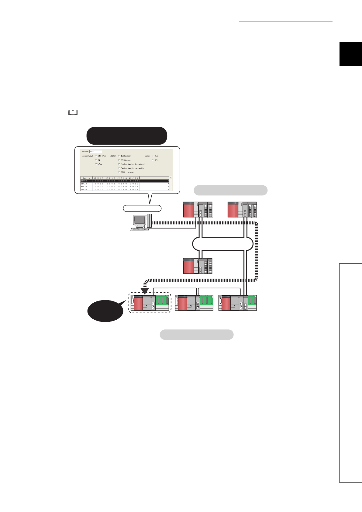
3.4 List of I/O Signals
This section lists I/O signals for the safety CPU module.
The I/O signal assignment of when the start I/O number of the master/local module is "0000" (the module is mounted
to the 0 slot of the safety main base unit) is shown below.
The device X is an input signal from the master/local module to the safety CPU module. The device Y is an output
signal from the safety CPU module to the master/local module.
Signal direction: Master/local module Safety CPU
module
Signal direction: Safety CPU module Master/local
module
Device number Signal name Device number Signal name
X0 Module failure Y0
X1 Own station data link status Y1
X2 Use prohibited Y2
X3 Other stations data link status Y3
X4
X5 Y5
X6 Y6
X7 Y7
X8 Y8
X9 Y9
XA YA
XB YB
XC YC
XD YD
XE YE
XF Module ready YF
X10
X11 Y11
X12 Y12
X13 Y13
X14 Y14
X15 Y15
X16 Y16
X17 Y17
X18 Y18
X19 Y19
X1A Y1A
X1B Y1B
X1C Y1C
X1D Y1D
X1E Y1E
X1F Y1F
Use prohibited
Use prohibited
Y4
Y10
Use prohibited
40
Page 43

CHAPTER 3 SPECIFICATIONS
● Do not use (turn on) any "use prohibited" signals as an input or output signal to the safety CPU module.
Doing so may cause malfunction of the programmable controller system.
● For details on the I/O signals, refer to "I/O Signals". ( Page 264, Appendix 1)
3
3.4 List of I/O Signals
41
Page 44

3.5 List of Buffer Memory Addresses
The buffer memory is used to exchange data between the master/local module and the safety CPU module.
The buffer memory values are defaulted when the power is turned off or the safety CPU module is reset.
Address
(Decimal
Name
(Hexadecimal))
0 to 1023
(0 to 3FF
)
H
1024 to 2047
to 7FFH)
(400
H
2048 to 10239
to 27FFH)
(800
H
10240 to 18431
(2800
to 47FFH)
H
Link device area
18432 to 18463
to 481FH)
(4800
H
18464 to 18975
to 4A1FH)
(4820
H
18976 to 19455
to 4BFFH)
(4A20
H
System area
19456
)
(4C00
H
19457
)
(4C01
H
to to
RX offset/size information
19694
(4CEE
)
H
19695
)
(4CEF
H
19696 to 19711
to 4CFFH)
(4CF0
H
System area
19712
)
(4D00
H
19713
)
(4D01
H
to to
RY offset/size information
19950
(4DEE
)
H
19951
)
(4DEF
H
19952 to 19967
to 4DFFH)
(4DF0
H
System area
Remote input (RX)
Remote output (RY)
Remote register (RWw)
Remote register (RWr) Read
Link special relay (SB)
Link special register (SW)
Station No. 1 RX offset
Station No. 1 RX size
Station No. 120 RX offset
Station No. 120 RX size
Station No. 1 RY offset
Station No. 1 RY size
Station No. 120 RY offset
Station No. 120 RY size
Initial
value
Read, write Refer to
Read, write
0
• 18432 to 18433 for
read and write
• 18434 to 18463 for
read only
• 18464 to 18495 for
read and write
• 18496 to 18975 for
read only
0 Read
0 Read
Read
Page 266,
Appendix 2.1
Page 269,
Appendix 2.2
Page 269,
Appendix 2.3
42
Page 45

CHAPTER 3 SPECIFICATIONS
Address
(Decimal
Name
(Hexadecimal))
19968
)
(4E00
H
19969
)
(4E01
H
to to
20206
(4EEE
)
H
20207
)
(4EEF
H
20208 to 20223
to 4EFFH)
(4EF0
H
20224
)
(4F00
H
20225
)
(4F01
H
to to
20462
(4FEE
)
H
20463
)
(4FEF
H
20464 to 20511
to 501FH)
(4FF0
H
20512
)
(5020
H
20513
)
(5021
H
20514
)
(5022
H
20515
)
(5023
H
20516 to 20519
to 5027H)
(5024
H
20520
)
(5028
H
20521
)
(5029
H
20522
)
(502A
H
20523
)
(502B
H
20524
)
(502C
H
20525 to 20534
to 5036H)
(502D
H
20535 to 20536
to 5038H)
(5037
H
RWw offset/size information
System area
RWr offset/size information
System area
Own station (network card)
information
System area
Own station (controller)
information
Initial
value
Station No. 1 RWw offset
Station No. 1 RWw size
0 Read
Station No. 120 RWw offset
Station No. 120 RWw size
Station No. 1 RWr offset
Station No. 1 RWr size
0 Read
Station No. 120 RWr offset
Station No. 120 RWr size
Manufacturer code 0
Model type 1
Model code 6 or 7
Ver sio n *1
Controller information
valid/invalid flag
Manufacturer code
Model type
Model code
Ver sio n
Model name string
Vendor-specific device
information
0 Read, write
Read, write Refer to
Page 270,
Appendix 2.4
Page 270,
Appendix 2.5
Read
Page 271,
Appendix 2.6
Page 271,
Appendix 2.6
3
3.5 List of Buffer Memory Addresses
43
Page 46

Address
(Decimal
(Hexadecimal))
20537 to 20538
to 503AH)
(5039
H
20544
)
(5040
H
20545
)
(5041
H
20546
H)
(5042
20547
(5043
H)
20548 to 20551
to 5047H)
(5044
H
20552
)
(5048
H
20553
)
(5049
H
20554
)
(504A
H
20555
)
(504B
H
20556
)
(504C
H
20557 to 20566
to 5056H)
(504D
H
20567 to 20568
to 5058H)
(5057
H
20569 to 20575
(5059
to 505FH)
H
20576 to 24383
to 5F3FH)
(5060
H
24384 to 31767
to 7FFFH)
(5F40
H
*1 Since the version of a master/local module is stored, the initial value depends on the master/local module used.
Name
Initial
value
Read, write Refer to
System area
Manufacturer code
Other station (network card)
information (station No. 1)
Model type
0 Read
Model code
Page 272,
Appendix 2.7
Versi on
System area
Controller information
valid/invalid flag
Manufacturer code
Model type
Page 272,
Appendix 2.7
Other station (controller
information) (station No. 1)
Model code
Versi on
0 Read
Model name string
Vendor-specific device
information
System area
Other station information
(station No. 2 to No. 120)
Same as other station information (station No. 1)
System area
44
Do not write data to "System area".
Doing so may cause malfunction of the programmable controller system.
Page 47

CHAPTER 4 PROCEDURES BEFORE OPERATION
Remark
Check box
Consider the system configuration and link device assignments.
System consideration
Installation
Mount the master/local module to the safety main base unit.
Safety CPU operation mode check
Check that the safety CPU module is in test mode (the TEST LED
of the safety CPU module is on) after power-on.
Unit test
Perform a unit test on each module.
Wiring
Cable check
Perform a cable test on the master/local module.
To the next page
Connect an Ethernet cable to each module.
Page 47, CHAPTER 5
Page 96, Section 8.1.1
Page 103, Section 8.2.1
QSCPU User's Manual
(Hardware Design,
Maintenance and Inspection)
Page 64, Section 6.3
Page 59, Section 6.1
Page 60, Section 6.2
Manual for slave stations
Page 74, Section 6.4.2
CHAPTER 4 PROCEDURES BEFORE OPERATION
This chapter lists the procedures to be performed before operation of CC-Link IE Field Network.
The programming chapter in this manual provides examples for each procedure (from “System consideration” to “Debug”)
described below. ( Page 209, CHAPTER 11)
4
45
Page 48

Check box
Set the parameters for each module.
Configuration
Create a program.
Programming
Debug the program by using CC-Link IE Field Network diagnostics.
Debug
Change the safety CPU operation mode to safety mode using
GX Developer.
Safety CPU operation mode change
(to safety mode)
Network diagnostics
Perform a loop test on the master station, and check if it can properly
communicate by the configured parameters.
Page 77, CHAPTER 7
Page 67, Section 6.4.1
Page 209, CHAPTER 11
Page 124, CHAPTER 9
QSCPU User's Manual
(Hardware Design,
Maintenance and Inspection)
46
Page 49

CHAPTER 5 SYSTEM CONFIGURATION
Local station
(safety station)
Switching hub
Ethernet cable
(1000BASE-T)
Master station
(safety station)
Up to 31 stations1 station
CHAPTER 5 SYSTEM CONFIGURATION
5.1 CC-Link IE Field Network Configuration
This section describes CC-Link IE Field Network configurations.
The master/local module operates as the following station in CC-Link IE Field Network:
• Master station (safety station)
• Local station (safety station)
• Local station (standard station)
5.1.1 Single network system
(1) Overall system configuration
Single network system is a system that consists of a master station and slave stations connected by Ethernet
cables.
(a) Configuring a system using safety stations only
One master station (safety station) and up to 31 local stations (safety stations) can be connected.
5
5.1 CC-Link IE Field Network Configuration
5.1.1 Single network system
47
Page 50

(b) Configuring a system using safety stations and standard stations
Local station (safety station)
Local station
(standard station)
Switching hub
Ethernet cable
(1000BASE-T)
Master station
(standard station)
Up to 32 stations
Slave station
Up to 120 stations
1 station
One master station (standard station) and up to 120 slave stations can be connected per network. Up to 32
safety stations can be connected per network.
When a safety station is set as a master station, the following restrictions apply:
• Some dedicated instructions cannot be used. ( Page 317, Appendix 7.2)
• Interlink transmission is not available.
The maximum number of safety connections per master/local module is as follows:
• Asynchronous mode: 31 connections
• Synchronous mode: 8 connections
48
Page 51

CHAPTER 5 SYSTEM CONFIGURATION
Star topology Line topology
Star and line topologies mixed
Switching hub
Switching hub Switching hub
Ring topology
(2) Network configuration
(a) Network topology
The network can be wired into star topology, line topology, and ring topology.
A network can consist of a combination of star and line topologies, but the ring topology cannot be combined
with star or line topology.
5
Item Description
The network is configured into a star using a switching hub and Ethernet cables.
Slave stations can be easily added to the network using this topology. (Add slave stations
Star topology
Line topology
one by one. If multiple slave stations are added at a time, all stations on the network will be
reconnected. Therefore, an error may momentarily occur in all the stations.)
Data link continues with the stations that are operating normally.
The network is configured into a line by connecting the modules with Ethernet cables, but
without a switching hub. If an error occurs, stations after the faulty station will be
disconnected.
Master station (safety station)
(Station No. 0)
*1
Line topology
Stations after the faulty station are disconnected.
5.1 CC-Link IE Field Network Configuration
5.1.1 Single network system
Fault
49
Page 52

Remark
Item Description
Station No. 1
Station No. 0
(
Master station
)
(safety station)
Station No. 3 Station No. 2
Switching hub
Up to 20-layer
cascade connection
The network is configured into a ring using Ethernet cables.
Data link continues with the stations that are operating normally.
*1
Ring topology
Master station (safety station)
Ring topology
*1 Add/remove slave stations one by one. If multiple slave stations are added/removed at a time, all stations on the network
will be reconnected, and an error may momentarily occur in all the stations.
(Station No. 0)
Fault
The system will continue data link among
normal stations only.
(b) Station number and connection position
Modules can be connected in any order regardless of the station number.
(c) Cascade connection
Up to 20-layer connection is available for the cascade connection.
50
For wiring method, refer to Page 64, Section 6.3.
Page 53

CHAPTER 5 SYSTEM CONFIGURATION
Switching hub
Cannot connect both Ethernet ports
to the switching hub.
Switching hub
(3) Precautions
(a) Connecting devices to the same network
Do not connect Ethernet devices (e.g. personal computer) other than CC-Link IE Field Network devices to the
switching hub used by CC-Link IE Field Network. Doing so will cause timeout in the master station, resulting in
disconnection of all the stations.
(b) Configuration in which data link cannot be performed (incorrectly configured ring
topology)
Do not wire devices as shown below. Doing so will cause an error in all stations and data link cannot be performed.
• Connecting both PORT1 and PORT2 to the switching hub
Ex.
5
• Ring topology through a switching hub
Ex.
5.1 CC-Link IE Field Network Configuration
5.1.1 Single network system
51
Page 54

(c) Ring topology
Master station (safety station)
No loopback is detected. No loopback is detected.
Station in Offline mode
Master station (safety station)
No loopback is detected. No loopback is detected.
Station in Offline mode
Fault
To configure a ring topology, select "Use" under "Loopback Function Setting" in the network parameter window
for the master station. ( Page 81, Section 7.3)
(d) Using a switching hub to configure a ring topology
If ring topology is configured by connecting two stations through two of the switching hub's ports, the following
problems may arise:
• If an Ethernet cable is disconnected, loopback cannot be detected.
• If a station is disconnected due to failure or power-off, data link will stop.
Therefore, do not use a switching hub to configure the ring topology.
Switching hub
(e) Offline mode station in ring topology
In the following cases, the master station or the station connected to the offline mode station cannot detect
loopback.
• One of the Ethernet cables connected to the offline mode station is disconnected.
• A station connected to the offline mode station is disconnected.
To detect loopback, set the offline mode station as a reserved station.
When the offline mode station is disconnected, loopback can be detected.
A station during the RESET status and a station with no station number setting operate as an offline mode station does.
52
Page 55

CHAPTER 5 SYSTEM CONFIGURATION
(f) Connecting/disconnecting a cable and powering off/on a device
When the operations listed below are performed, all stations on the network may be reconnected.
At that time, a data link error or a baton pass error may momentarily occur in all the stations, and outputs of the
connected slave stations may turn off.
Network configuration Operation
• Powering a slave station or switching hub off and on
• Connecting/disconnecting an Ethernet cable connected to the switching hub
• Disconnecting an Ethernet cable from a slave station and connecting it to another
Star topology
Line topology, ring topology
slave station or the switching hub
• Disconnecting more than nine stations, or half the number of slave stations or more in
the system
• Changing the network topology when adding a slave station
• Simultaneously powering off/on systems on multiple stations
• Simultaneously connecting/disconnecting Ethernet cables to/from multiple stations
(When a data link faulty station returns, a data link error will occur in all the stations.)
• Disconnecting more than nine stations, or half the number of slave stations or more in
the system
• Changing the network topology when adding a slave station
5
Momentary
error in all
the stations
Insertion/removal
or power-off/power-on
To hold the outputs as a measure when a data link error occurs, configure the following settings:
• Master/local module
Set input data to be used from the faulty station.
Project data list [Parameter] [Network param] [Ethernet/CC IE/MELSECNET]
button
Note that data input by safety communication is cleared even if the above setting is configured.
5.1 CC-Link IE Field Network Configuration
5.1.1 Single network system
53
Page 56

(g) Connected station numbers
Station No. 0 Station No. 1 Station No. 1 Station No. 2
(Data link may stop.)
Duplication
Do not duplicate station numbers. Data link may be stopped when the station number is duplicated.
(h) Power-on order
To avoid incorrect input from slave stations, power on slave stations before the master station.
(i) Submaster function
A master/local module cannot be used as a submaster station.
In addition, if a safety station is used in a system which includes a submaster station, an error may occur in
safety communications when the control is switched between a master station and a submaster station.
54
Page 57

CHAPTER 5 SYSTEM CONFIGURATION
CC-Link IE
Controller Network
Network No. 2
CC-Link IE
Field Network
Network No. 1
(Relay station)
5.1.2 Multi-network system
The multi-network system is a system in which multiple networks are connected by some relay stations. Up to 239
networks can be connected.
5
● Only one master/local module can be mounted on a safety base unit. Therefore, a safety programmable controller cannot
● Safety communications can be achieved among safety stations on the same network.
● Cyclic transmission communication is available only in the same network.
● Transient transmission communication is available with other networks as well as the same network. Communications
relay more than one CC-Link IE Field Network. To relay more than one CC-Link IE Field Network systems, use a
standard programmable controller.
can be made with stations up to eight networks apart (number of relay stations: 7). ( Page 154, Section 10.1 (1) (b))
5.1 CC-Link IE Field Network Configuration
5.1.2 Multi-network system
55
Page 58

5.2 Network Components
Remark
CC-Link IE Field Network consists of components such as cables and hubs.
5.2.1 Cables
For wiring, use the 1000BASE-T compliant Ethernet cables.
Ethernet cable Connector Type
Category 5e or higher
(Double shielded/STP) Straight cable
● For CC-Link IE Field Network wiring, use the recommended wiring components by CC-Link Partner Association.
● Cables for CC-Link IE Controller Network cannot be used for CC-Link IE Field Network.
(1) Product
Cables for CC-Link IE Field Network are available from Mitsubishi Electric System & Service Co., Ltd. (Catalogs
for cable are also available.)
Also, the connector processing of cable length is available for your preference. Please consult your local
Mitsubishi Electric System & Service Co., Ltd.
Typ e Model (manufacturer)
CC-Link IE Field Network cable SC-E5EW series (Mitsubishi Electric System & Service Co., Ltd.)
RJ45 connector
The following conditioning cables:
• IEEE802.3 (1000BASE-T)
• ANSI/TIA/EIA-568-B (Category 5e)
● Cable types
The following cable types are available depending on the operating environment:
• Standard type: Cables for inside the control panel and indoor connection
• L type: Cables for outdoor connection
Cables and relay adapters of flame retardant or waterproof type are also available. Please contact your Mitsubishi
Electric System & Service Co., Ltd.
56
Page 59

5.2.2 Hubs
Use hubs that meet all the conditions listed below:
• Compliance with the IEEE802.3 (1000BASE-T)
• Support of the auto MDI/MDI-X function
• Support of the auto-negotiation function
• Switching hub (layer 2 switch)
Operation is not guaranteed if the hubs do not meet these conditions.
*1 A repeater hub is not available.
(1) Mitsubishi product
Type Model name
Industrial switching hub NZ2EHG-T8
*1
CHAPTER 5 SYSTEM CONFIGURATION
5
5.2.2 Hubs
5.2 Network Components
57
Page 60

5.3 Applicable Systems
Master/local module
Programming tool available for
master/local modules
Applicable CPU modules, and the
number of mountable modules
Page 58, Section 5.3 (1)
Page 58, Section 5.3 (2)
This section describes MELSEC-QS series systems that include the master/local module.
(1) Applicable safety CPU modules and the number of mountable modules
(a) Safety CPU module
The following safety CPU module is applicable to the master/local module.
Safety CPU module Serial number (first five digits)
QS001CPU 13042 or later
(b) Number of mountable modules
For the number of mountable modules, refer to the following.
QSCPU User's Manual (Hardware Design, Maintenance and Inspection)
(c) Mounting to a MELSECNET/H remote I/O station
The master/local module cannot be mounted to any MELSECNET/H remote I/O stations. Mount the module on
a safety base unit on which a safety CPU module is mounted.
(2) Applicable programming tool
GX Developer is required for setting and diagnosing master/local modules.
GX Works2 cannot be used.
Software Vers ion
GX Developer Version 8.98C or later
(3) Module replacement
Replacing the module before the following time elapses is recommended.
Module Replacement time
Master/local module 10 years
58
Page 61

CHAPTER 6 INSTALLATION AND WIRING
CHAPTER 6 INSTALLATION AND WIRING
This chapter describes the installation and wiring of a master/local module.
6.1 Installation
This section describes the installation of a master/local module.
(1) Handling precautions
The following is a list of precautions for handling the master/local module:
• Do not drop or apply strong shock to the module case since it is made from resin. Doing so may cause
failure.
• Do not remove the printed-circuit board of the module from the case. Doing so may cause failure.
• Prevent foreign matter such as dust or wire chips from entering the module. Such foreign matter can cause a
fire, failure, or malfunction.
• A protective film is attached to the top of the module to prevent foreign matter, such as wire chips, from
entering the module during wiring. Do not remove the film during wiring. Remove it for heat dissipation
before system operation.
• Before handling the module, touch a grounded metal object to discharge the static electricity from the human
body. Failure to do so may cause the module to fail or malfunction.
• Tighten the screws such as module fixing screws within the following range.
Screw Tightening torque range
Module fixing screw (M3 × 12) 0.36 to 0.48N•m
6
6.1 Installation
• To mount the module, while pressing the module mounting lever located in the lower part of the module, fully
insert the module fixing projection(s) into the hole(s) in the base unit and press the module until it snaps into
place. Be sure to tighten the module fixing screw within the specified tightening torque range.
Incorrect mounting may cause malfunction, failure or drop of the module.
(2) Installation environment
For details on installation environment, refer to the following.
QSCPU User's Manual (Hardware Design, Maintenance and Inspection)
59
Page 62

6.2 Tests Before Wiring
Select "H/W test".
Select one from the followings:
"CC IE Field (Master station [Safety])",
"CC IE Field (Local station [Safety])",
or "CC IE Field (Local station)".
RUN
SD
ERR.
MST
D LINK
RD
L ERR.
1
2
4
8
MODE
100
10
1
S
T
N
O
.
.
1
2
4
8
1
: ON
: Flashing
This section describes module tests that should be performed before network wiring.
6.2.1 Hardware test
Hardware test checks the hardware inside the master/local modules.
(1) Procedure
1. Mount the master/local module on the safety base
unit, and connect GX Developer to the safety CPU
module.
An Ethernet cable is not connected to the master/local
modules.
2. Set network parameters in GX Developer as
shown in the figure to left.
or powering off on
Project data list [Parameter] [Network
param] [Ethernet/CC IE/MELSECNET]
3. Write the network parameters set in GX Developer
to the safety CPU module.
[Online] [Write to PLC]
4. Reset the safety CPU module or power off and on
the system.
5. Hardware test begins.
The MODE LED of master/local modules flashes, and
each of the ×1 LED repeatedly turns on and off (1 2
4 8 1 • • •).
60
Page 63

CHAPTER 6 INSTALLATION AND WIRING
Remark
RUN
SD
ERR.
MST
D LINK
RD
L ERR.
1
2
4
8
MODE
S
T
N
O
.
.
1
2
4
8
1
RUN
SD
ERR.
MST
D LINK
RD
L ERR.
1
2
4
8
MODE
S
T
N
O
.
.
1
2
4
8
1
100
10
1
100
10
1
: ON
When completed
: Flashing
: ON
When failed
: Flashing
6. D LINK LED turns on when the test is completed.
• When completed
The ×1 LED turns off.
• When failed
Any one of the ×1 LEDs turns on, and the ERR. LED turns
on.
When the test fails, the possible cause is hardware failure
of the master/local modules. Please consult your local
Mitsubishi service center or representative with the
detailed problem description.
6
The test status and result can be checked through monitoring the link special relays on GX Developer.
Item Description
When completed
When failed
• Hardware test completion status (SB0090): ON
• Hardware test normal/abnormal end (SB0091): OFF
• Hardware test completion status (SB0090): ON
• Hardware test normal/abnormal end (SB0091): ON
(2) Precautions
(a) Settings
Do not enter values for "Network Configuration Setting" and "Refresh parameters". When link refresh is
executed during a hardware test, the test may fail.
(b) Operations
Do not access the buffer memory through the program during the hardware test. Doing so may cause the test
to fail.
6.2 Tests Before Wiring
6.2.1 Hardware test
61
Page 64

6.2.2 Self-loopback test
Select "Self-loopback test".
Select one from the followings:
"CC IE Field (Master station [Safety])",
"CC IE Field (Local station [Safety])",
or "CC IE Field (Local station)".
Ethernet cable
or powering off on
Self-loopback test checks the communication circuit of the master/local module.
When conducting the self-loopback test, use a normal Ethernet cable. ( Page 56, Section 5.2)
1. Mount the master/local module on the safety
2. Set network parameters in GX Developer as
base unit, and connect GX Developer to the
safety CPU module.
shown in the figure to left.
Project data list [Parameter] [Network
param] [Ethernet/CC IE/MELSECNET]
3. Write the network parameters set in GX
Developer to the safety CPU module.
[Online] [Write to PLC]
4. Connect PORT1 and PORT2 of the master/local
modules with an Ethernet cable. ( Page 64,
Section 6.3)
5. Reset the safety CPU module or power off and on
the system.
62
Page 65

CHAPTER 6 INSTALLATION AND WIRING
Remark
RUN
SD
ERR.
LINK
P1
L ER
MST
D LINK
RD
L ERR.
1
2
4
8
MODE
S
T
N
O
.
.
1
2
4
8
1
LINK
P2
L ER
100
10
1
: ON
: Flashing
RUN
SD
ERR.
MST
D LINK
RD
L ERR.
1
2
4
8
MODE
S
T
N
O
.
.
1
2
4
8
1
RUN
SD
ERR.
MST
D LINK
RD
L ERR.
1
2
4
8
MODE
S
T
N
O
.
.
1
2
4
8
1
100
10
1
100
10
1
: ON
When completed
: Flashing
: ON
When failed
: Flashing
6. Self-loopback test begins.
The MODE LED of master/local modules flashes,
and each of the ×10 LED repeatedly turns on and off
(1 2 4 8 1 • • •).
Also, the SD LED, RD LED, and LINK LED turn on.
7. D LINK LED turns on, and SD LED and RD LED
turn off when the test is completed.
• When completed
The ×10 LED turns off.
• When failed
Any one of the ×10 LEDs turns on, and the ERR. LED
turns on. If the test fails, replace the Ethernet cable and
execute the test again. If the test fails again, the
possible cause is hardware failure of the master/local
modules. Please consult your local Mitsubishi service
center or representative with the detailed problem
description.
6
The test status and result can be checked through monitoring the link special relays on GX Developer.
Item Description
When completed
When failed
• Self-loopback test completion status (SB0092): ON
• Self-loopback test normal/abnormal end (SB0093): OFF
• Self-loopback test completion status (SB0092): ON
• Self-loopback test normal/abnormal end (SB0093): ON
6.2 Tests Before Wiring
6.2.2 Self-loopback test
63
Page 66

6.3 Wiring
This section describes the cable wiring and precautions. For network configuration, cables, and hubs used for the
wiring, refer to the system configuration. ( Page 47, CHAPTER 5)
(1) Ethernet cable connection
(a) Connecting the cable
1. Power off the master/local module and the
connected device.
2. Push the Ethernet cable connector into the
master/local module until it clicks. Pay attention to
the connector's direction.
3. Power on the master/local module and the
connected device.
4. Check whether the LINK LED of the port connected
L ER
P1
LINK
with an Ethernet cable is on.
The time between the power-on and the LINK LED
turning on may vary. The LINK LED usually turns on in a
few seconds. Note, however, that the time may be
extended further if the linkup process is repeated
depending on the status of the device on the line.
If the LINK LED does not turn on, refer to the
troubleshooting section and take corrective actions.
( Page 239, Section 12.3)
64
Page 67

CHAPTER 6 INSTALLATION AND WIRING
PORT1 and PORT2 need not to be distinguished.
• When only one connector is used in star topology, either PORT1 or PORT2 is applicable.
L ER
P1
LINK
L ER
P2
LINK
QS0J71GF11-T2
Either one can be used.
• When using two connectors for line topology and ring topology, an Ethernet cable can be connected to the
connectors in any combination. For example, the cable can be connected between PORT1s or between PORT1
and PORT2.
Connection between
PORT1s or PORT2s
L ER
P1
LINK
L ER
P2
LINK
QS0J71GF11-T2 QS0J71GF11-T2 QS0J71GF11-T2
L ER
P1
LINK
L ER
P2
LINK
L ER
P1
LINK
L ER
P2
LINK
(b) Disconnecting the cable
Connection between
PORT1 and PORT2
L ER
P1
LINK
L ER
P2
LINK
QS0J71GF11-T2 QS0J71GF11-T2 QS0J71GF11-T2
L ER
P1
LINK
L ER
P2
LINK
L ER
P1
LINK
L ER
P2
LINK
1. Power off the system.
2. Press the latch down and unplug the Ethernet cable.
6
6.3 Wiring
65
Page 68

(2) Precautions
This section describes wiring precautions.
(a) Handling
• Place the Ethernet cable in a duct or clamp them. If not, dangling cable may swing or inadvertently be pulled,
resulting in damage to the module or cables or malfunction due to poor contact.
• Do not touch the core of the cable-side or module-side connector, and protect it from dirt or dust. If oil from
your hand, dirt or dust is attached to the core, it can increase transmission loss, arising a problem in data
link.
• Check the following:
• Is any Ethernet cable disconnected?
• Is any of the Ethernet cables shorted?
• Are the connectors securely connected?
(b) Broken cable latch
Do not use Ethernet cables with broken latches. Doing so may cause the cable to unplug or malfunction.
(c) Connecting and disconnecting the Ethernet cable
Hold the connector part when connecting and disconnecting the Ethernet cable. Pulling a cable connected to
the module may damage the module or cable, or result in malfunction due to poor contact.
(d) Connectors without Ethernet cable
Attached connector cover should be placed to prevent foreign matter such as dirt or dust.
(e) Maximum station-to-station distance (maximum cable length)
The maximum station-to-station distance is 100m. However, the distance may be shorter depending on the
operating environment of the cable. For details, contact your cable manufacturer.
(f) Bend radius
The bend radius of the Ethernet cable is limited. For details, see the specifications of the Ethernet cable to be
used.
(g) Network configuration
For wiring, check Page 49, Section 5.1.1 (2) and Page 51, Section 5.1.1 (3) to prevent incorrect wiring
66
Page 69

CHAPTER 6 INSTALLATION AND WIRING
Master station
(safety station)
Local station
(safety station)
Local station
(safety station)
Local station
(safety station)
6.4 Tests After Wiring
This section describes loop and cable tests that should be performed after network wiring.
Perform these tests to the actual operating network configuration.
6.4.1 Loop test
The loop test checks each station's network line and parameter setting status to verify whether the network is
operating correctly.
The test completes approximately in 10 seconds.
Start testing from the master station. To use a standard programmable controller for the master station, refer to the
following manual.
User’s manual for the CC-Link IE Field Network master/local module used
The test allows checking of the following items:
Item Description
Master station duplication check Checks if the master station is duplicated.
Station number duplication check Checks if stations on the network are duplicated.
Out-of-range station No. check
Reserved station specification
check
Consistency check of the number
of connected stations
Station type check
Loopback check
Checks if the number of connected slave stations exceeds the number of slave stations
set to the master station.
Checks if the specified reserved stations are actually connected.
Consistency check for the number of total slave stations set by parameters and actual
connected slave stations.
Consistency check for the station type of slave stations set in master stations and actual
connected station type.
Detects whether loopback is being performed when "Use" is selected under "Loopback
Function Setting" in the network parameter window for the master station.
(1) Performing a loop test
This section describes the procedure using the following system configuration example.
6
6.4 Tests After Wiring
6.4.1 Loop test
67
Page 70

(a) Preparing for a loop test
Remark
Select "Online."
In the case of a local station (safety station)
Select
"CC IE Field (Local
station [Safety])".
Ex.
Master station
(safety station)
After wiring, set the local stations (safety stations) to online mode before executing the loop test.
1. Connect GX Developer to the CPU module.
2. Set the local stations (safety stations) to online
mode by GX Developer.
Local station (safety station)
3. Reset the slave stations or power off and on to
set the mode to online.
For slave stations other than the local station where the master/local module is mounted, also set their mode to online. For
the setting method of slave stations, refer to the manual of the slave station used.
68
Page 71

(b) Procedure
Master station
(safety station)
Select "Loop test".
Select
"CC IE Field (Master
station [Safety])".
or powering off on
RUN
SD
ERR.
MST
D LINK
RD
L ERR.
MODE
S
T
N
O
.
.
1
1
2
4
8
1
2
4
8
RUN
SD
ERR.
MST
D LINK
RD
L ERR.
MODE
S
T
N
O
.
.
1
1
2
4
8
1
2
4
8
100
10
1
100
10
1
: ON
Local station (safety station)
Master station (safety station)
: Flashing
Perform a loop test from the master station (safety station).
CHAPTER 6 INSTALLATION AND WIRING
1. Connect GX Developer to the safety CPU module.
2. Set network parameters in GX Developer as
shown in the figure to left.
6
Project data list [Parameter] [Network
param] [Ethernet/CC IE/MELSECNET]
3. Configure the network configuration setting in the
network parameter. ( Page 81, Section 7.3)
Project data list [Parameter] [Network
param] [Ethernet/CC IE/MELSECNET]
6.4 Tests After Wiring
6.4.1 Loop test
button
4. Write the network parameters set in GX Developer
to the safety CPU module.
[Online] [Write to PLC]
5. Reset the safety CPU module or power off and on
the system.
6. Loop test begins.
• Master station (safety station)
The MODE and D LINK LEDs flash. Also, each of the
×10 LED and ×1 LED repeatedly turns on and off (1 2
4 8 1 • • •).
However, if errors are detected, the test is immediately
terminated (failure).
• Local station (safety station)
Data link stops on all stations. Also, the MODE, D LINK,
and ×100 LEDs flash.
69
Page 72

RUN
SD
ERR.
MST
D LINK
RD
L ERR.
1
2
4
8
MODE
S
T
N
O
.
.
1
2
4
8
1
RUN
SD
ERR.
MST
D LINK
RD
L ERR.
1
2
4
8
MODE
S
T
N
O
.
.
1
2
4
8
1
100
10
1
100
10
1
: ON
When completed
: Flashing
: ON
When failed
: Flashing
Select "Online
(Normal Mode)"
or "Online
(High Speed Mode)".
7. Check the test result with LEDs of the master
station (safety station). D LINK LED turns on when
the test is completed.
• When completed
The ×10 and ×1 LEDs turn off.
• When failed
Any one of the ×10 and ×1 LEDs turns on, and the ERR.
LED turns on. Error details can be specified depending
on the lighting status of ×10 and ×1 LEDs.
Master station duplication
1
1
Station No. duplication
2
2
Invalid station No.
4
4
Reserved station specification error
8
8
(A station that exists on the network is set
1
10
as a reserved station in the master station.)
Loopback stations exist.
Station type setting error
Inconsistent number of total slave
stations
All stations faulty
Identify the error location through GX Developer or
link special register (SW), and take actions.
( Page 72, Section 6.4.1 (2))
8. When the loop test is completed, slave stations
will be in online mode.
Set the master station (safety station) to "Online
(Normal Mode)" or "Online (High Speed Mode)"
through the network parameter.
70
Write the network
parameters to the
Safety CPU module.
or Power OFF ON
During the loop test, data link stops on all stations.
Page 73

CHAPTER 6 INSTALLATION AND WIRING
Remark
The test status and result can be viewed through monitoring the link special relays on GX Developer.
Item Description
When completed
When failed
• Loop test completion status (SB0094): ON
• Loop test normal/abnormal end (SB0095): OFF
• Loop test completion status (SB0094): ON
• Loop test normal/abnormal end (SB0095): ON
6
6.4 Tests After Wiring
6.4.1 Loop test
71
Page 74

(2) Actions if the loop test fails
Click
or powering off on
(a) Checking by GX Developer
In the CC-Link IE Field Network diagnostics, identify the error location and take action. Then, execute the loop
test again.
1. Open the "CC IE Field Diagnostics" window.
[Diagnostics] [CC IE Field diagnostics]
2. The error location is displayed on top of the
diagnostic window.
3. Click the error location.
4. Click the button on the bottom right of the window
to display the error descriptions.
5. Reset the safety CPU module on the master station
(safety station) or power off and on the system to
retry the loop test.
With CC-Link IE Field Network diagnostics, a station where network number mismatch, master station duplication, station
number duplication, or station type error occurs cannot be selected. Check the error details by directly connecting GX
Developer to the faulty station and displaying the system monitor window. ( Page 261, Section 12.6)
72
Page 75

CHAPTER 6 INSTALLATION AND WIRING
(b) Checking by link special register (SW)
Identify the error location by link special register (SW) and take actions. After the actions, execute the loop test
again.
1. Check the error locations and descriptions by link special register (SW), and take actions.
Error cause Action
Master station duplication, station number
duplication, out-of-range station No.,
reserved station specification, or station
type
All station errors or inconsistent number of
connected stations
Loopback stations exist.
Parameter error status (each station) (SW0170 to SW0177) checks error
locations.
Take corrective actions by checking error codes on Parameter setting status
(SW004C). ( Page 246, Section 12.5)
Identify the error stations on baton pass status (each station) (SW00A0 to
SW00A7). The following actions are taken on error stations.
• Replace the Ethernet cable.
• Adjust the total number of slave stations set to the master station (safety
station) to the number of connected slave stations.
• Check if the station set in the network configuration setting of GX Developer
matches with the connected station.
• Set the station number for the station where a station number is not set.
• Replace the master/local modules.
The network is not configured in ring topology or is incorrectly configured.
( Page 49, Section 5.1.1 (2))
Check connection status of stations between the stations specified at Loopback
station number 1 (SW0070) and Loopback station number 2 (SW0071), and
connected Ethernet cables.
To use a network configuration other than the ring topology, clear the "Use"
checkbox under "Loopback Function Setting" in the network parameter window
for the master station (safety station).
2. Reset the safety CPU module on the master station (safety station) or power off and on the system
to retry the loop test.
6
6.4 Tests After Wiring
6.4.1 Loop test
73
Page 76

6.4.2 Cable test
Station No. 0 Station No. 1 Station No. 2 Station No. 3
Cable test checks if the Ethernet cables are properly connected.
Only the Ethernet cable connected to the PORT1 or PORT2 of the target station is tested. For the whole network
status, perform the loop test. ( Page 67, Section 6.4.1)
1. Connect GX Developer to the safety CPU
module.
2. Open the "Cable Test" window.
[Diagnostics] [CC IE Field diagnostics]
button
3. Enter a station number and click the
button to operate the test. If an error occurs, take
corrective actions according to the error
message.
74
Page 77

CHAPTER 6 INSTALLATION AND WIRING
Communication
target
Own station
(request source)
CC-Link IE
Field Network
CC-Link IE
Field Network
CC-Link IE
Field Network
Station
No. 2
Station
No. 1
Station
No. 3
Station
No. 0
Station
No. 0
Station
No. 2
Station
No. 4
Station
No. 0
(Relay
station 1)
Station
No. 2
Station
No. 3
(Relay
station 2)
Station
No. 1
Network No. 1 Network No. 3
Network No. 2
Routing parameters for stations of network No. 1
No setting is required for station
No. 3 because data are transmitted
via the station itself.
Routing parameters for stations of network No. 2
Routing parameters for stations of network No. 3
No setting is required for station
No. 3 because data are transmitted
via the station itself.
No setting is required for station
No. 0 because data are transmitted
via the station itself.
No setting is required for station
No. 2 because data are transmitted
via the station itself.
6.4.3 Communication test
Communication test checks if transient transmission data can be properly routed from the own station to the
communication target.
Take the following system configuration as an example of communication test procedure.
6
CC-Link IE
Field Network
Own station
(request source)
Station
No. 2
Network No. 1 Network No. 3
Station
No. 1
Station
No. 0
Station
No. 3
GX Developer
(Relay
station 1)
Station
No. 0
Network No. 2
CC-Link IE
Field Network
Station
No. 1
(Relay
station 2)
Station
No. 2
CC-Link IE
Field Network
Station
No. 0
Station
No. 3
Communication
target
Station
No. 2
Station
No. 4
1. Connect GX Developer to the safety CPU module.
2. Set routing parameters in GX Develoepr as shown in
the figure to left. ( Page 92, Section 7.7)
Project data list [Parameter] [Network
param] [Ethernet/CC IE/MELSECNET]
button
75
6.4 Tests After Wiring
6.4.3 Communication test
Page 78

3. Write the network parameters set in GX Developer
or powering off on
Own station
(request source)
Station
No. 0
Station
No. 1
Station
No. 2
Receiving
(relay) station
Sending
(relay) station
Station
No. 0
Network No. 1
Network No. 2
to the safety CPU module.
[Online] [Write to PLC]
4. Reset the safety CPU module or power off and on
the system.
5. Open the "Communication Test" window and enter
values for "Target Station" and "Communication
Data Setting".
[Diagnostics] [CC IE Field diagnostics]
button
6. Click the button to perform the
communication test. If an error occurs, take actions
according to the error message.
76
When conducting the test on relay stations, set the receiving (relay) station in "Target Station". Setting the sending (relay)
station will cause an error.
Page 79

CHAPTER 7 PARAMETER SETTING
1
2
3
5
6
4
1
CHAPTER 7 PARAMETER SETTING
This chapter describes CC-Link IE Field Network parameters.
The network parameters are set for either the master station or slave stations.
This manual describes network parameters for master/local modules. For slave station settings, refer to the manuals
for the slave stations used.
7.1 Parameter List
The following table lists CC-Link IE Field Network parameters.
(1) Parameters set for a master/local module
The following table lists parameters that need to be set for safety and standard communications.
7
7.1 Parameter List
: Always, : When required, : Cannot be set
Setting
Master
Item
Network type
Starting I/O No.
Network No.
Network setting
Total stations
Station No.
Mode
station
(safety
station)
Local
station
(safety
station)
Local
station
(standard
station)
Reference
Page 79, Section
7.2
77
Page 80

Network Configuration
2
3
4
5
6
Setting
Network Operation
Setting
Refresh parameters
Safety Communication
Setting
Routing parameters
*1 This parameter needs to be set for standard communication (needs not to be set for safety communication).
Setting
Master
Item
station
(safety
station)
Station No.
Station Type
RX/RY Setting
RWw/RWr Setting
Reserved/Error Invalid Station
Alias
Comment
Supplementary
Setting
Parameter Name
Data Link Faulty Station Setting
Output Setting During CPU STOP
Communication Target Station No.
Open Method
Transmission Interval Monitoring Time
Safety Refresh Monitoring Time
Safety Data Transfer Device Setting
*1
*1
Link Scan Mode
Setting
Loopback Function
Setting
Block Data
Assurance per
Station
Local
station
(safety
station)
Local
station
(standard
station)
Page 81, Section
7.3
Page 85, Section
7.4
Page 86, Section
7.5
Page 90, Section
7.6
Page 92, Section
7.7
Reference
Always set parameters. Failure to do so will cause "NETWORK PARAMETER ERROR" in the safety CPU module.
78
Page 81

7.2 Network Setting
Set the network number, station number, and other parameters for the master/local module.
(1) Setting procedure
1. Open the setting window in GX Developer.
Project data list [Parameter] [Network param] [Ethernet/CC IE/MELSECNET]
2. Set parameters in the window.
3. Click the button.
CHAPTER 7 PARAMETER SETTING
Item Description Setting range
Select whether to use the master/local module as a master station
Network type
Starting I/O No.
Network No. Enter the network number of the master/local module. 1 to 239 (Default: Blank)
Total stations
Station No.
(safety station) or a local station.
Only one master station (safety station) can be set for one network.
Enter the start I/O number of the master/local module in increments of
16 points.
Enter the number of slave stations connected to the master station
(safety station) including reserved slave stations.
This setting is available when "CC IE Field (Master Station [Safety])" is
selected in "Network type".
Enter the station number of the master/local module. Set a station
number different from those used in the same network.
Note that the master station (safety station) number is fixed at "0".
• CC IE Field (Master station [Safety])
• CC IE Field (Local station [Safety])
• CC IE Field (Local station)
(Default: Blank)
Within the number of I/O points of the
safety CPU module (Default: Blank)
1 to 120 (Default: Blank)
• Master station (safety station): Fixed
at "0".
• Local station: 1 to 120
(Default: Blank)
7
7.2 Network Setting
79
Page 82

Mode
Mode Description
Online (Normal Mode)
This mode performs cyclic transmission and
transient transmission without losing their inherent
speed performance. This mode is suitable for a
system that performs I/O control and analog
control, and transmits large amount of data for
management, monitoring, and diagnostics by
transient transmission.
Use this mode for general applications.
Online (High Speed
Mode)
This mode preferentially performs cyclic
transmission for high-speed communications.
Note that the maximum number of points assigned
to RWw/RWr is 256 points per local station.
In this mode, the processing speed of transient
transmission is slower than in "Online (Normal
Mode)".
Offline
Select this mode to disconnect the master/local
module from the network for stopping data link with
other stations.
H/W test
Select this mode to perform a hardware test.
( Page 60, Section 6.2.1)
Self-loopback test
Select this mode to perform a self-loopback test.
( Page 62, Section 6.2.2)
Loop test
Select this mode to perform a loop test.
( Page 67, Section 6.4.1)
Mode Description
Online
Select this mode to connect the master/local
module to the network for performing data link with
other stations.
Offline
Select this mode to disconnect the master/local
module from the network for stopping data link with
other stations.
H/W test
Select this mode to perform a hardware test.
( Page 60, Section 6.2.1)
Self-loopback test
Select this mode to perform a self-loopback test.
( Page 62, Section 6.2.2)
Item Description Setting range
Select a master station (safety station) mode.
Two online modes are available. Select an online mode according to
the system.
• Online (Normal Mode)
• Online (High Speed Mode)
•Offline
• H/W test
• Self-loopback test
• Loop test
(Default: Online (Normal Mode))
(2) Setting example
80
For setting example, refer to Page 209, CHAPTER 11.
Select a local station mode.
•Online
•Offline
• H/W test
• Self-loopback test
(Default: Online)
Page 83

CHAPTER 7 PARAMETER SETTING
7.3 Network Configuration Setting
Set parameters of slave stations (the number of points and assignment of link devices) in the master station (safety
station). Also, set link scan mode and block data assurance per station.
This setting is available when "CC IE Field (Master Station [Safety])" is selected in network setting.
(1) Setting procedure
1. Configure network setting. ( Page 79, Section 7.2)
2. Open the setting window in GX Developer.
Project data list [Parameter] [Network param] [Ethernet/CC IE/MELSECNET]
button
3. Set parameters in the window.
4. Click the button.
Item Description Setting range
Assignment Method
Number of PLCs
Station No.
Station Type
Select a link device assignment method.
• Points/Start: Enter the points and start numbers of link devices.
• Start/End: Enter the start and end numbers of link devices.
Displays the number of slave stations set for "Total Stations" in
network setting.
Enter the number of a slave station connected to the network.
Station numbers can be set at random (cannot be duplicated).
Select a slave station type. Select the station type same as that of the
slave station connected to the network.
• Points/Start
• Start/End
(Default: Start/End)
1 to 120
(Starting from 1 (default), numbers are
displayed by the value set in "Total
stations" in network setting.)
• Remote I/O Station
• Remote Device Station
• Intelligent Device Station
• Local Station
(Default: Intelligent Device Station)
7.3 Network Configuration Setting
7
81
Page 84

Item Description Setting range
Station Type
Setting
range
Local Station, Intelligent
Device Station
16 to 2048
Remote Device Station 16 to 128
Remote I/O Station 16 to 64
Station Type
Setting
range
Local Station, Intelligent
Device Station
4 to 1024
Remote Device Station 4 to 64
Remote I/O Station
Cannot be
set.
RX/RY Setting
Set assignment for RX/RY for each slave station. ( Page 103,
Section 8.2.1)
Enter values in increments of 16 points (Start: 0
F
).
H
, End:
H
• Points:
RWw/RWr Setting
Set assignment for RWw/RWr in increments of 4 points for each slave
station. ( Page 103, Section 8.2.1)
Link devices of the master/local module to be transferred by link
refresh and the transfer target safety CPU module devices are
Refresh Device
displayed.
This item is displayed when refresh parameters have been set.
( Page 86, Section 7.5)
Set this item to reserve the slave station or to set the slave station as
an error invalid station. ( Page 119, Section 8.4, Page 120,
Section 8.5)
• No Setting
The slave station is connected to the network.
• Reserved Station
The slave station is reserved for future expansion. By reserving a
slave station, link device assignment will not change even if the
Reserved/Error Invalid
Station
slave station is added or the reservation is cancelled. Therefore, the
program needs not to be modified. Physical connection of the slave
station is not required.
• Invalid Station
Even if a slave station is disconnected during data link, the master
station (safety station) will not detect the slave station as a faulty
station. However, if a local station (safety station) set as an error
invalid station or a temporary error invalid station is disconnected,
an error will occur in safety communication with the disconnected
station.
Alias Enter the name of a device on the slave station if required.
Comment Enter the comment of the slave station if required.
• Device number: 0 to 3FFF
(Default: Blank)
• Points:
• Device number: 0 to 1FFF
(Default: Blank)
• No Setting
• Reserved Station
• Invalid Station
(Default: Blank)
Up to 8 characters
(Default: Blank)
Up to 32 characters
(Default: Blank)
H
H
82
Page 85

CHAPTER 7 PARAMETER SETTING
(1) Link Scan Mode Setting
Item Description
Asynchronous
Link scan is performed asynchronously with the
sequence scan of the safety CPU module.
Select this item to shorten input transmission delay
time when sequence scan takes much time than link
scan. Note that output transmission delay time will
become longer.
Constant Scan
Cyclic transmission is performed punctually. Link scan
time will be the constant link scan time set in this
setting.
However, when the actual link scan time is longer than
the specified link scan time, cyclic transmission is
performed by actual link scan time.
While constant link scan is used to keep link scan time
constant, the transmission delay time is not kept
constant by this function. To keep transmission delay
time constant, select "Synchronous".
Synchronous
Link scan is performed synchronously with the
sequence scan of the safety CPU module. Select this
item in the following cases:
• To shorten output transmission delay time (Note
that when sequence scan takes much time than link
scan, input transmission delay time will become
longer.)
• To keep transmission delay time constant
*1
Item Description Setting range
Set link scan mode and block data assurance per station.
button
*1 The sequence scan must be constant as well.
Set "Constant Scanning" in the "PLC RAS" of the
PLC Parameter window.
(2) Loopback Function Setting
Select whether to use the loopback function. ( Page 121,
Section 8.6) To configure a network in ring topology, select the
checkbox.
(3) Block Data Assurance per Station
Select whether to assure data integrity on a station basis in link
refresh between the safety CPU module and the master/local
module. ( Page 106, Section 8.2.3)
• Link Scan Mode Setting:
Asynchronous, Synchronous
(Default: Asynchronous)
• Loopback Function Setting:
Selected (Use)/not selected
(Default: Not selected)
• Block Data Assurance per Station:
Selected (Assure Block Data)/not
selected
(Default: Selected)
7.3 Network Configuration Setting
7
83
Page 86

button
Item Description
Start station
Enter the start station number of slave stations for which
link devices are equally assigned.
End station
Enter the end station number of slave stations for which
link devices are equally assigned.
Star t N o.
Enter the start number of link devices to be equally
assigned.
Total points
assigned
Enter the total points of link devices to be equally
assigned.
Item Description Setting range
Equally assign link devices to slave stations with preset conditions.
• Start station: 1 to the end slave
station number
• End station: Number set to "Start
station" to the end slave station
Assign the same link device points to all slave stations. Enter the
points in the field right next to the button.
number
• Start No.: Same values set in "RX/RY
Setting" and "RWw/RWr Setting"
• Total points assigned: Same values
set in "RX/RY Setting" and
"RWw/RWr Setting"
(Default: Blank)
button
Points entered in this field will be reflected to the "Points" of "RX/RY
Setting".
Half of the points entered in this field will be reflected to the "Points" of
"RWw/RWr Setting".
(2) Precautions
When "Synchronous" is set under "Link Scan Mode Setting" of "Supplementary Setting", observe the following.
• Change the program or the system configuration so that the sequence scan time of the safety CPU module
may be within 200ms. Failure to do so may cause disconnection of slave stations.
• Set the sequence scan time of safety CPU modules on local stations (safety stations) so that it may be
longer than or equal to the link scan time.
If the sequence scan time is shorter than the link scan time, an error occurs in safety communication. To
avoid this, set the constant scan time of the safety CPU modules on the local stations (safety stations).
For how to calculate link scan time, refer to Page 303, Appendix 5.2.
For how to set the constant scan time of a safety CPU module, refer to the following.
QSCPU User’s Manual (Function Explanation, Program Fundamentals)
(3) Setting example
For setting example, refer to Page 209, CHAPTER 11.
84
Page 87

7.4 Network Operation Setting
Set operating status of a network if a data link error occurs or the safety CPU module is set to STOP.
1. Configure network setting. ( Page 79, Section 7.2)
2. Open the setting window in GX Developer.
Project data list [Parameter] [Network param] [Ethernet/CC IE/MELSECNET]
button
3. Set parameters in the window.
CHAPTER 7 PARAMETER SETTING
Item Description Setting range
Parameter Name Enter the name of network operation setting parameters if desired. Up to 8 characters
Data Link Faulty Station
Setting
Output Setting During
CPU STOP
Select whether to hold or clear data input by standard communication
from the slave station where a data link error has occurred.
( Page 113, Section 8.2.5)
Data input by safety communication will be cleared regardless of this
setting and safety CPU operation mode.
Select whether to hold or clear cyclic data output when the safety CPU
module mounted with the master/local module is set to STOP.
( Page 115, Section 8.2.6)
• Turn OFF or 0 Clear Input Data
(RX/RY)
• Hold Input Data (RX/RY)
(Default: Turn OFF or 0 Clear Input
Data (RX/RY))
•Hold
• Clear (ALL OFF)
(Default: Hold)
7
7.4 Network Operation Setting
85
Page 88

7.5 Refresh Parameters
Set the ranges of link devices of the master/local module and safety CPU module devices for which link refresh is to be
performed.
(1) Setting procedure
1. Configure network setting. ( Page 79, Section 7.2)
2. Open the setting window in GX Developer.
Project data list [Parameter] [Network param] [Ethernet/CC IE/MELSECNET]
button
3. Set parameters in the window.
4. Click the button.
Item Description Setting range
Assignment method
Select a link device assignment method.
• Points/Start: Enter the points and start numbers of link devices.
• Start/End: Enter the start and end numbers of link devices.
• Points/Start
• Start/End
(Default: Start/End)
86
Page 89

CHAPTER 7 PARAMETER SETTING
Ex.
0000
H
Device
name
(SB)
Transfer
SB
Transfer
SW
01FFH
Master/local module Safety CPU module
0000H
01FFH
0000H
01FFH
0000H
01FFH
Device
name
(SW)
Device
name
(SB)
Device
name
(SW)
Item Description Setting range
Select link refresh ranges of SB and SW. Link refresh range can be
set for both "Transfer SB" and "Transfer SW" by 1. ( Page 104,
Section 8.2.2)
(1) Transfer SB
• Link side: Fixed at "SB".
• PLC side: M, B, D, W, SB
Transfer SB
Transfer
SW
Transfer 1
to 8
Dev. name
Points,
Start, End
Dev. name
Points,
Start, End
Select link refresh ranges of RX, RY, RWr, and RWw. Link refresh
ranges can be set up to 8. ( Page 104, Section 8.2.2)
Ex.
0000
00FF
0000
00FF
0000
00FF
0000
00FF
H
Device
name
(RX)
H
H
Device
name
(RY)
H
H
Device
name
(RWr)
H
H
Device
name
(RWw)
H
Transfer
1
Transfer
2
Transfer
3
Transfer
4
Device
name
(X)
Device
name
(Y)
Device
name
(W)
Device
name
(W)
1000
10FF
1000
10FF
0000
00FF
0100
01FF
H
H
H
H
H
H
H
H
(2) Transfer SW
• Link side: Fixed at "SW".
• PLC side: M, B, D, W, SW
(Default: Blank)
• Link side: 0 to 1FF
H
• PLC side: Within device range of
safety CPU module
(Default: Blank)
Set bit devices in increments of 16
points and word devices in increments
of 4 points.
• Link side: RX, RY, RWr, RWw
• PLC side:
When RX is set to “Link Side”:
X, M, B, D, W
When RY is set to “Link Side”:
Y, M, B, T, C, ST, D, W
When RWr is set to “Link Side”:
M, B, D, W
When RWw is set to “Link Side”:
M, B, T, C, ST, D, W
(Default: Blank)
• Link side:
0 to 3FFF
0 to 1FFF
for RX/RY
H
for RWr/RWw
H
• PLC side: Within device range of
safety CPU module
(Default: Blank)
Set bit devices in increments of 16
points and word devices in increments
of 4 points.
7
7.5 Refresh Parameters
button
Reset refresh parameters to default.
Master/local module Safety CPU module
87
Page 90

(2) Checking method
1) Click
2) Set
"Device (PLC side)",
"Device (Link side)", and
"Display magnification".
3) The assignment
image is displayed.
1. Clicking the button in the "Network parameters Setting the number of Ethernet/CC
IE/MELSECNET cards." window will open the "assignment image" window.
( Page 79, Section 7.2)
2. Select a device to be displayed and the magnification ratio in the window, and check the image of
refresh parameter assignment.
88
3. A red part in the CPU side device indicates that the device in the red part overlaps with the device
set for another refresh parameter. Correct the refresh parameters.
Page 91

CHAPTER 7 PARAMETER SETTING
(3) Precautions
(a) Device set to "Device (PLC side)"
Set a device range that differs from the one used for the following:
• Refresh parameters for other network modules
• Auto refresh parameters for CC-Link Safety master module
• I/O numbers used for network modules
(b) Link refresh range
Set only link devices used in the safety CPU module for link refresh range. Doing so will reduce link refresh
points, resulting in a shorter link refresh time.
(c) Changing link device assignment in the "Network Configuration Setting" window
Correct the link refresh ranges of refresh parameters.
(4) Setting example
For setting example, refer to Page 209, CHAPTER 11.
7
7.5 Refresh Parameters
89
Page 92

7.6 Safety Communication Setting
Set safety communication parameters for stations that perform safety communication.
This setting can be configured when "CC IE Field (Master station [Safety])" and "CC IE Field (Local station [Safety])"
are set in network setting.
(1) Setting procedure
1. Open the setting window in GX Developer.
Project data list [Parameter] [Network param] [Ethernet/CC IE/MELSECNET]
button
2. Set parameters in the window.
3. Click the button.
Item Description Setting range
Assignment Method
Total Number of Stations
Host Station No.
90
Select how to assign safety CPU module devices.
• Points/Start: Set devices by the number of device points and the
start number.
• Start/End: Set devices by the start and last device numbers.
When “CC IE Field (Master station [Safety])” is selected in network
setting, the number of slave stations set in “Total stations” is
displayed.
When “CC IE Field (Local station [Safety])” is selected in network
setting, the number of slave stations is not displayed.
When “CC IE Field (Master station [Safety])” is selected in network
setting, “0” is displayed.
When “CC IE Field (Local station [Safety])” is selected in network
setting, own station number set to “Station No.” in network setting is
displayed.
• Points/Start
• Start/End
(Default: Start/End)
Page 93

Item Description Setting range
Device Range
Bit devices 16 to 128
Word devices 1 to 8
Device Range
Bit devices 16 to 128
Word devices 1 to 8
Device range of the
safety CPU module
Start
End
Transmission Interval
Monitoring Time
Communication Target Station
No.
Open Method
Safety Refresh Monitoring
Time (m s)
In each safety connection, batch-set monitoring time for a receiving
station to detect safety communication errors.
( Page 308, Appendix 5.4)
Set the communication target’s station number.
Select how to establish safety connection.
• Active: Establishes safety connection from the own station.
• Passive: Establishes safety connection upon request from the
communication target station.
In each safety connection, set monitoring time for a receiving station
to detect safety communication errors.
Set this item for the Active side of the stations that perform safety
communication. ( Page 309, Appendix 5.5)
Set a CPU module device where safety data are stored.
CHAPTER 7 PARAMETER SETTING
1 to 1000
(Default: 25)
• Master station (safety station):
1 to 120
• Local station: 0 to 120
(Default: Blank)
•Active
•Passive
(Default: Active)
2 to 2000
(Default: 60)
Safety Data
Transfer Device
Setting
Receive
Data
Storage
Device
Send Data
Storage
Device
Ex.
0000
H
Device
name
007F
H
Safety CPU module
(own station)
(X)
Safety data
reception
(communication target station)
Device
Safety CPU module
Set a CPU module device from where safety data are sent.
Ex.
0000
H
001F
H
Device
name
(Y)
Safety data
transmission
Device
• Device Name: X, M, B, D, W
• Points:
Start
End
Device range of the
safety CPU module
(Default: Blank)
Set bit devices in units of 16
points and word devices in units
of 1 points.
• Device Name: Y, M, B, T, C,
ST, D, W
• Points:
7
7.6 Safety Communication Setting
button
Safety CPU module
(own station)
Safety CPU module
(communication target station)
Batch-set “Safety Refresh Monitoring Time”. ( Page 309,
Appendix 5.5)
Enter the time in the area right to the
button.
(Default: Blank)
Set bit devices in units of 16
points and word devices in units
of 1 points.
2 to 2000 (Default: Blank)
91
Page 94

7.7 Routing Parameters
Ex.
Set communication paths for transient transmission between a station in the own network and stations in other
networks.
(1) Setting procedure
1. Open the setting window in GX Developer.
Project data list [Parameter] [Network param] [Ethernet/CC IE/MELSECNET]
button
2. Set parameters in the window.
3. Click the button.
Item Description Setting range
Set a relay station through which data are sent to stations in other networks by
transient transmission in the own network. Up to 8 communication paths can
be set.
Target network No.
Set routing parameters as shown below.
Setting to transmit data to network number ● by transient transmission
To go to network No. , data passes through station No. of its own network No. .
Relay network No. 1 to 239 (Default: Blank)
No routing parameter setting is required for
network No. because the module of
network No. is mounted on the relay station.
Station that needs
routing parameters
Relay station No. 0 to 120 (Default: Blank)
Network No.
(Relay station)
Network No.
*1
1 to 239 (Default: Blank)
92
Page 95

CHAPTER 7 PARAMETER SETTING
1
121
*1 Routing parameters need not to be set for stations for which routing parameters are not available (e.g. station including
a head module). The station communicates with other networks according to routing parameters set to the master
station.
● Transient transmission range
Communications can be made with stations up to eight networks apart (number of relay stations: 7).
● Setting for stations that do not perform transient transmission to other networks
Routing parameters are not required for stations that do not perform transient transmission to other networks; however,
setting the same routing parameters to all stations is recommended.
Station which does not perform
transient transmission
Network No.
(Relay station)
Network No.
It is recommended to set the same routing parameters as for .
and can communicate by the same routing parameters,
since they pass through the same relay station.
Note that routing parameters need not to be set for stations for which routing parameters are not available (e.g. station
including a head module). The station communicates with other networks according to routing parameters set to the
master station.
(2) Checking method
To check whether routing parameters have been correctly set and transient transmission can be performed,
perform a communication test from CC-Link IE Field Network diagnostics. ( Page 75, Section 6.4.3)
(3) Precautions
(a) Different control CPUs are set to the network modules on a relay station in a
multiple CPU system
Set the same routing parameters to all the control CPUs.
7
7.7 Routing Parameters
2
Set the same routing parameters.
2
Control CPU setting
93
Page 96

(b) When multiple master/local modules with the same network number are connected
Station
No.0
Slot No. 0 1 2
Station
No.1
Station
No.2
Station
No.3
CPU
module
Station
No.0
Network No.1
Set "1" in "Relay Station No.".
Network No.2
to one system
Set the station number of a module with the smallest slot number in "Relay Station No.".
In a multiple CPU system, set the station number of a module with the smallest slot number, regardless of the
CPU number of the control CPU.
94
Page 97

(4) Setting example
Relay
station 1
Relay
station 2
Request
target
Request
source
Station Transient transmission (request) Transient transmission (response)
331
Relay
network No.
Goes through station No. 3 of
network No. 1 to reach network No. 3.
342
Target
network No.
Goes through station No. 4 of
network No. 2 to reach network No. 3.
Passes data to the request target
on network No. 3.
112
Goes through station No. 1 of
network No. 2 to reach network No. 1.
Passes data to the request source
on network No. 1.
Automatically passes data to
the relay station.
(Setting for relay station 2)(Setting for request target)
Network No. 1
CC-Link IE Field Network
Master station
Station
No. 0
Station
No. 5
Station
No. 1
Station
No. 4
Station
No. 2
Station
No. 3
Station
No. 1
Station
No. 4
Station
No. 5
Station
No. 4
Station
No. 1
Station
No. 2
Station
No. 3
(Request source)
Network No. 3
(Request target)
(Relay station 2)(Relay station 1)
(Setting for relay station 1)
Station
No. 2
Station
No. 3
Station
No. 1
Station
No. 3
Station
No. 1
Station
No. 4
Station
No. 4
Station
No. 5
Station
No. 4
Station
No. 5
Station
No. 2
Station
No. 3
Network No. 2
Station
No. 2
Relay
station
No.
Relay
network No.
Target
network No.
Relay
station
No.
Relay
network No.
Target
network No.
Relay
station
No.
The following shows an example to perform transient transmission from the station number 2 in the network
number 1 to the station number 4 in the network number 3.
CHAPTER 7 PARAMETER SETTING
7
7.7 Routing Parameters
95
Page 98

CHAPTER 8 FUNCTIONS
This chapter explains the functions of the master/local module.
8.1 Safety Communication Function
This section explains functions related to safety communication.
8.1.1 Communication with safety stations
One-on-one safety communication is available periodically between safety stations on the same network. The
following devices are used for data communication: X, Y, M, B, D, W, T, ST, and C.
96
Page 99

CHAPTER 8 FUNCTIONS
2
1 3
4
Master
station
(safety station)
Local
station
(safety station)
Safety CPU
module
Device
ENDENDEND
Device
Sequence
scan
M0
Y
Station No. 0
Safety CPU
module
Device
Device
Sequence
scan
ENDENDEND
M0
Y
Station No. 1
Safety connection
establishment
Safety data transfer
Safety data transfer
1
2
3
4
(1) Safety communication flow
After a safety connection is established, safety data is sent periodically from safety stations on both stations.
The device status in the safety CPU module on a station (sending side) is stored into a device in the safety CPU
module on the other station (receiving side). The figure below is an example of safety communication between a
master station (safety station) and a local station (safety station). Safety communication between local stations
(safety station) is also the same.
• Output from a master station (safety station)
The device in the safety CPU module on a master station (safety station) turns on.
The device status in the safety CPU module on the master station (safety station) is stored into the
device in the safety CPU module on the local station (safety station) by safety data transfer.
• Output from a local station (safety station)
The device in the safety CPU module on a local station (safety station) turns on.
The device status in the safety CPU module on the local station (safety station) is stored into the
device in the safety CPU module on the master station (safety station) by safety data transfer.
8.1.1 Communication with safety stations
8
8.1 Safety Communication Function
97
Page 100

(2) Setting method
Assign devices to be used for safety communication in the safety communication setting.
( Page 90, Section 7.6)
Devices used for safety communication are highlighted in yellow or green in ladder programs on GX Developer.
( GX Developer Version 8 Operating Manual (Safety Programmable Controller))
The following figure is an example of a ladder program with a device highlighted in yellow.
Highlighted in yellow
● If an error occurs in safety communication, safety data from a station with an error is cleared.
● A safety connection can be established only while baton bass is performed after configuring the safety communication
setting of both stations (sending side and receiving side).Note that stations not set to the network configuration setting of
the master station and reserved stations cannot establish a safety connection. Check whether a safety connection is
established or not at special registers (SD1420 to SD1427) (Safety refresh communication status of each safety station)
and a special relay (SM1421) (Safety refresh communication status of safety master station).
( QSCPU User’s Manual (Function Explanation, Program Fundamentals))
● The following data can be held only when the safety CPU mode is set to the test mode: output data of safety
communication when the safety CPU module is on the STOP status. ( Page 115, Section 8.2.6)
98
 Loading...