

Page 1

CC-Link IE Field Network Ethernet Adapter Module
User's Manual
-NZ2GF-ETB
Page 2

Page 3
SAFETY PRECAUTIONS
(Read these precautions before using this product.)
Before using this product, please read this manual and the relevant manuals carefully and pay full attention
to safety to handle the product correctly.
In this manual, the safety precautions are classified into two levels: " WARNING" and " CAUTION".
WARNING
CAUTION
Under some circumstances, failure to observe the precautions given under " CAUTION" may lead to
serious consequences.
Observe the precautions of both levels because they are important for personal and system safety.
Make sure that the end users read this manual and then keep the manual in a safe place for future
reference.
Indicates that incorrect handling may cause hazardous conditions,
resulting in death or severe injury.
Indicates that incorrect handling may cause hazardous conditions,
resulting in minor or moderate injury or property damage.
[Design Precautions]
WARNING
● Configure safety circuits external to the Ethernet adapter module to ensure that the entire system
operates safely even when a fault occurs in the external power supply or the Ethernet adapter
module. Failure to do so may result in an accident due to an incorrect output or malfunction.
The Ethernet adapter module will stop its operation if it detects an error such as a watchdog timer
error by the self-diagnostic function.
● When changing data from a peripheral device connected to the Ethernet adapter module during
operation, configure an interlock circuit in the program of another station to ensure that the entire
system will always operate safely.
For other controls to a running programmable controller on another station (such as program
modification or operating status change) or the operating status change of the Ethernet adapter
module, read relevant manuals carefully and ensure the safety before the operation. Especially, in the
case of a control from an external device to a remote programmable controller on another station,
immediate action cannot be taken for a problem on the programmable controller due to a
communication failure. To prevent this, configure an interlock circuit on the program on another
station, and determine corrective actions to be taken between the external device and the
programmable controller in case of a communication failure.
● Do not write any data to the "system area" and "write-protect area" (R) of the buffer memory in the
Ethernet adapter module. Doing so may cause malfunction of the Ethernet adapter module.
1
Page 4
[Design Precautions]
CAUTION
● Do not install the communication cables together with the main circuit lines or power cables. Keep a
distance of 100mm or more between them. Failure to do so may result in malfunction due to noise.
[Installation Precautions]
CAUTION
● Use the Ethernet adapter module in an environment that meets the general specifications in this
manual. Failure to do so may result in electric shock, fire, malfunction, or damage to or deterioration of
the product.
● Do not directly touch any conductive parts and electric components of the Ethernet adapter module.
Doing so can cause malfunction or failure of the Ethernet adapter module.
[Wiring Precautions]
WARNING
● Shut off the external power supply (all phases) used in the system before wiring. Failure to do so may
result in electric shock or cause the Ethernet adapter module to fail or malfunction.
● After wiring, attach the included terminal cover to the module before turning it on for operation. Failure
to do so may result in electric shock.
[Wiring Precautions]
CAUTION
● Individually ground the FG and LG terminals of the programmable controller with a ground resistance
of 100 or less. Failure to so may result in electric shock or malfunction.
● Use applicable solderless terminals and tighten them within the specified torque range. If any spade
solderless terminal is used, it may be disconnected when a terminal block screw comes loose,
resulting in failure.
● Check the rated voltage and terminal layout before wiring to the Ethernet adapter module, and
connect the cables correctly. Connecting a power supply with a different voltage rating or incorrect
wiring may cause a fire or failure.
● Securely connect the connector to the Ethernet adapter module.
● Do not install the communication cables together with the main circuit lines or power cables. Failure to
do so may result in malfunction due to noise.
● Place the cables connected to the Ethernet adapter module in a duct or clamp them. If not, dangling
cable may swing or inadvertently be pulled, resulting in damage to the Ethernet adapter module or
cables or malfunction due to poor contact.
2
Page 5

[Wiring Precautions]
CAUTION
● Tighten the terminal block screw within the specified torque range. Undertightening can cause short
circuit, fire or malfunction. Overtightening can damage the screw and/or Ethernet adapter module,
resulting in drop, short circuit, or malfunction.
● When disconnecting the cable from the Ethernet adapter module, do not pull the cable by the cable
part. For the cable with connector, hold the connector part of the cable. Pulling the cable connected to
the Ethernet adapter module may result in malfunction or damage to the module or cable.
● Prevent foreign matter such as dust or wire chips from entering the Ethernet adapter module. Such
foreign matter can cause a fire, failure, or malfunction.
● A protective film is attached to the top of the Ethernet adapter module to prevent foreign matter, such
as wire chips, from entering the module during wiring. Do not remove the film during wiring. Remove it
for heat dissipation before system operation.
● The Ethernet adapter module must be installed in a control panel. Connect the main power supply
through a relay terminal block. Wiring and replacement of the Ethernet adapter module must be
performed by qualified maintenance personnel with knowledge of protection against electric shock.
For wiring methods, refer to "Wiring" in this manual.
[Startup and Maintenance Precautions]
WARNING
● Do not touch any terminal while power is on. Doing so will cause electric shock or malfunction.
● Shut off the external power supply for the system in all phases before cleaning the module or
retightening the terminal block screw. Failure to do so may result in electric shock.
[Startup and Maintenance Precautions]
CAUTION
● Before performing online operations (especially, program modification, forced output, and operating
status change) for the running Ethernet adapter module or programmable controller module on
another station from the peripheral device connected, read relevant manuals carefully and ensure the
safety. Improper operation may damage machines or cause accidents.
● Do not disassemble or modify the Ethernet adapter module. Doing so may cause failure, malfunction,
injury, or a fire.
● Use any radio communication device such as a cellular phone or PHS (Personal Handy-phone
System) more than 25cm away in all directions from the Ethernet adapter module. Failure to do so
may cause malfunction.
● Tighten the terminal block screw within the specified torque range. Undertightening can cause drop of
the component or wire, short circuit, or malfunction. Overtightening can damage the screw and/or
module, resulting in drop, short circuit, or malfunction.
● Before handling the Ethernet adapter module, touch a conducting object such as a grounded metal to
discharge the static electricity from the human body. Failure to do so may cause the Ethernet adapter
module to fail or malfunction.
3
Page 6

[Disposal Precautions]
CAUTION
● When disposing of this product, treat it as industrial waste.
4
Page 7

CONDITIONS OF USE FOR THE PRODUCT
(1) Mitsubishi programmable controller ("the PRODUCT") shall be used in conditions;
i) where any problem, fault or failure occurring in the PRODUCT, if any, shall not lead to any major
or serious accident; and
ii) where the backup and fail-safe function are systematically or automatically provided outside of
the PRODUCT for the case of any problem, fault or failure occurring in the PRODUCT.
(2) The PRODUCT has been designed and manufactured for the purpose of being used in general
industries.
MITSUBISHI SHALL HAVE NO RESPONSIBILITY OR LIABILITY (INCLUDING, BUT NOT
LIMITED TO ANY AND ALL RESPONSIBILITY OR LIABILITY BASED ON CONTRACT,
WARRANTY, TORT, PRODUCT LIABILITY) FOR ANY INJURY OR DEATH TO PERSONS OR
LOSS OR DAMAGE TO PROPERTY CAUSED BY the PRODUCT THAT ARE OPERATED OR
USED IN APPLICATION NOT INTENDED OR EXCLUDED BY INSTRUCTIONS, PRECAUTIONS,
OR WARNING CONTAINED IN MITSUBISHI'S USER, INSTRUCTION AND/OR SAFETY
MANUALS, TECHNICAL BULLETINS AND GUIDELINES FOR the PRODUCT.
("Prohibited Application")
Prohibited Applications include, but not limited to, the use of the PRODUCT in;
• Nuclear Power Plants and any other power plants operated by Power companies, and/or any
other cases in which the public could be affected if any problem or fault occurs in the PRODUCT.
• Railway companies or Public service purposes, and/or any other cases in which establishment of
a special quality assurance system is required by the Purchaser or End User.
• Aircraft or Aerospace, Medical applications, Train equipment, transport equipment such as
Elevator and Escalator, Incineration and Fuel devices, Vehicles, Manned transportation,
Equipment for Recreation and Amusement, and Safety devices, handling of Nuclear or
Hazardous Materials or Chemicals, Mining and Drilling, and/or other applications where there is a
significant risk of injury to the public or property.
Notwithstanding the above, restrictions Mitsubishi may in its sole discretion, authorize use of the
PRODUCT in one or more of the Prohibited Applications, provided that the usage of the PRODUCT
is limited only for the specific applications agreed to by Mitsubishi and provided further that no
special quality assurance or fail-safe, redundant or other safety features which exceed the general
specifications of the PRODUCTs are required. For details, please contact the Mitsubishi
representative in your region.
5
Page 8

INTRODUCTION
Thank you for purchasing the CC-Link IE Field Network Ethernet adapter module (hereinafter abbreviated as the
Ethernet adapter module).
This manual describes the operating procedure, system configuration, parameter setting, functions, and
troubleshooting of the Ethernet adapter module.
Before using this product, please read this manual and the relevant manuals carefully and develop familiarity with the
functions and performance of the Ethernet adapter module to handle it correctly.
When applying the program examples introduced in this manual to the actual system, ensure the applicability and
confirm that it will not cause system control problems.
Please make sure that the end users read this manual.
6
Page 9

RELEVANT MANUALS
(1) CC-Link IE Field Network related manual
When using CC-Link IE Field Network for the first time, refer to the CC-Link IE Field Network Master/Local
Module User's Manual. The following shows the system of CC-Link IE Field Network manuals.
Manual name
<manual number, model code>
MELSEC-Q CC-Link IE Field Network Master/Local Module
User's Manual
<SH-080917ENG, 13JZ47>
MELSEC-L CC-Link IE Field Network Master/Local Module User’s
Manual
<SH-080972ENG, 13JZ54>
MELSEC-QS CC-Link IE Field Network Master/Local Module
User's Manual
<SH-080969ENG, 13JZ53>
CC-Link IE Field Network Interface Board User's Manual (For
SW1DNC-CCIEF-B)
<SH-080980ENG, 13JZ58>
(2) Ethernet related manual
For communications using SLMP, refer to the following manual.
Manual name
<manual number, model code>
SLMP Reference Manual
<SH-080956ENG, 13JV23>
Description
Overview of CC-Link IE Field Network, and specifications, procedures
before operation, system configuration, installation, wiring, settings,
functions, programming, and troubleshooting of the MELSEC-Q series
master/local module
Overview of CC-Link IE Field Network, and specifications, procedures
before operation, system configuration, installation, wiring, settings,
functions, programming, and troubleshooting of the MELSEC-L series
master/local module
Overview of CC-Link IE Field Network, and specifications, procedures
before operation, system configuration, installation, wiring, settings,
functions, programming, and troubleshooting of the MELSEC-QS
series master/local module
Specifications, procedures before operation, system configuration,
settings, functions, programming, and troubleshooting of the CC-Link
IE Field Network interface board
Description
The protocol (SLMP) used for data reading or writing from an external
device to the Ethernet adapter module
7
Page 10

CONTENTS
CONTENTS
SAFETY PRECAUTIONS . . . . . . . . . . . . . . . . . . . . . . . . . . . . . . . . . . . . . . . . . . . . . . . . . . . . . . . . . . . . . 1
CONDITIONS OF USE FOR THE PRODUCT . . . . . . . . . . . . . . . . . . . . . . . . . . . . . . . . . . . . . . . . . . . . . 5
INTRODUCTION . . . . . . . . . . . . . . . . . . . . . . . . . . . . . . . . . . . . . . . . . . . . . . . . . . . . . . . . . . . . . . . . . . . . 6
RELEVANT MANUALS . . . . . . . . . . . . . . . . . . . . . . . . . . . . . . . . . . . . . . . . . . . . . . . . . . . . . . . . . . . . . . . 7
MANUAL PAGE ORGANIZATION . . . . . . . . . . . . . . . . . . . . . . . . . . . . . . . . . . . . . . . . . . . . . . . . . . . . . . 12
TERMS . . . . . . . . . . . . . . . . . . . . . . . . . . . . . . . . . . . . . . . . . . . . . . . . . . . . . . . . . . . . . . . . . . . . . . . . . . 13
PACKING LIST . . . . . . . . . . . . . . . . . . . . . . . . . . . . . . . . . . . . . . . . . . . . . . . . . . . . . . . . . . . . . . . . . . . . 15
CHAPTER 1 ETHERNET ADAPTER MODULE 16
CHAPTER 2 PART NAMES 22
2.1 Power Supply Part . . . . . . . . . . . . . . . . . . . . . . . . . . . . . . . . . . . . . . . . . . . . . . . . . . . . . . . . . . 23
2.2 CC-Link IE Field Network Part . . . . . . . . . . . . . . . . . . . . . . . . . . . . . . . . . . . . . . . . . . . . . . . . . 24
2.3 Ethernet Part. . . . . . . . . . . . . . . . . . . . . . . . . . . . . . . . . . . . . . . . . . . . . . . . . . . . . . . . . . . . . . . 28
CHAPTER 3 SPECIFICATIONS 29
3.1 General Specifications . . . . . . . . . . . . . . . . . . . . . . . . . . . . . . . . . . . . . . . . . . . . . . . . . . . . . . . 29
3.2 Performance Specifications . . . . . . . . . . . . . . . . . . . . . . . . . . . . . . . . . . . . . . . . . . . . . . . . . . . 30
3.2.1 Performance specifications of each part . . . . . . . . . . . . . . . . . . . . . . . . . . . . . . . . . . . . . . . . 31
3.3 List of the Functions . . . . . . . . . . . . . . . . . . . . . . . . . . . . . . . . . . . . . . . . . . . . . . . . . . . . . . . . . 36
3.4 Buffer Memory List . . . . . . . . . . . . . . . . . . . . . . . . . . . . . . . . . . . . . . . . . . . . . . . . . . . . . . . . . . 37
3.5 SLMP . . . . . . . . . . . . . . . . . . . . . . . . . . . . . . . . . . . . . . . . . . . . . . . . . . . . . . . . . . . . . . . . . . . . 43
3.5.1 Available command list . . . . . . . . . . . . . . . . . . . . . . . . . . . . . . . . . . . . . . . . . . . . . . . . . . . . . 43
3.5.2 Ranges of accessible devices and buffer memory. . . . . . . . . . . . . . . . . . . . . . . . . . . . . . . . . 44
CHAPTER 4 PROCEDURE BEFORE THE OPERATION 45
4.1 Start-Up Procedure. . . . . . . . . . . . . . . . . . . . . . . . . . . . . . . . . . . . . . . . . . . . . . . . . . . . . . . . . . 45
CHAPTER 5 SYSTEM CONFIGURATION 47
5.1 Network Configuration . . . . . . . . . . . . . . . . . . . . . . . . . . . . . . . . . . . . . . . . . . . . . . . . . . . . . . . 47
5.2 Network Components . . . . . . . . . . . . . . . . . . . . . . . . . . . . . . . . . . . . . . . . . . . . . . . . . . . . . . . .48
5.2.1 CC-Link IE Field Network. . . . . . . . . . . . . . . . . . . . . . . . . . . . . . . . . . . . . . . . . . . . . . . . . . . . 48
5.2.2 Ethernet . . . . . . . . . . . . . . . . . . . . . . . . . . . . . . . . . . . . . . . . . . . . . . . . . . . . . . . . . . . . . . . . . 48
5.3 Applicable Systems . . . . . . . . . . . . . . . . . . . . . . . . . . . . . . . . . . . . . . . . . . . . . . . . . . . . . . . . . 50
5.3.1 Configuration tool . . . . . . . . . . . . . . . . . . . . . . . . . . . . . . . . . . . . . . . . . . . . . . . . . . . . . . . . . . 50
5.3.2 Software package . . . . . . . . . . . . . . . . . . . . . . . . . . . . . . . . . . . . . . . . . . . . . . . . . . . . . . . . . 51
CHAPTER 6 INSTALLATION AND WIRING 52
6.1 Installation Environment . . . . . . . . . . . . . . . . . . . . . . . . . . . . . . . . . . . . . . . . . . . . . . . . . . . . . . 52
6.2 Installation. . . . . . . . . . . . . . . . . . . . . . . . . . . . . . . . . . . . . . . . . . . . . . . . . . . . . . . . . . . . . . . . . 52
6.2.1 Installation precautions . . . . . . . . . . . . . . . . . . . . . . . . . . . . . . . . . . . . . . . . . . . . . . . . . . . . . 52
6.2.2 Mounting the module to a control panel . . . . . . . . . . . . . . . . . . . . . . . . . . . . . . . . . . . . . . . . . 53
6.2.3 Mounting the modules on a DIN rail. . . . . . . . . . . . . . . . . . . . . . . . . . . . . . . . . . . . . . . . . . . . 54
6.3 Testing the Module Before Wiring. . . . . . . . . . . . . . . . . . . . . . . . . . . . . . . . . . . . . . . . . . . . . . .57
8
Page 11

6.4 Wiring . . . . . . . . . . . . . . . . . . . . . . . . . . . . . . . . . . . . . . . . . . . . . . . . . . . . . . . . . . . . . . . . . . . . 59
6.4.1 Wiring of the power supply part . . . . . . . . . . . . . . . . . . . . . . . . . . . . . . . . . . . . . . . . . . . . . . . 59
6.4.2 Ethernet cable wiring . . . . . . . . . . . . . . . . . . . . . . . . . . . . . . . . . . . . . . . . . . . . . . . . . . . . . . . 61
6.4.3 Grounding . . . . . . . . . . . . . . . . . . . . . . . . . . . . . . . . . . . . . . . . . . . . . . . . . . . . . . . . . . . . . . . 64
6.4.4 Precautions . . . . . . . . . . . . . . . . . . . . . . . . . . . . . . . . . . . . . . . . . . . . . . . . . . . . . . . . . . . . . . 65
CHAPTER 7 COMMUNICATION OF THE ETHERNET ADAPTER MODULE 66
7.1 SLMP Communication and Cyclic Transmission . . . . . . . . . . . . . . . . . . . . . . . . . . . . . . . . . . . 66
7.1.1 System configuration . . . . . . . . . . . . . . . . . . . . . . . . . . . . . . . . . . . . . . . . . . . . . . . . . . . . . . . 66
7.1.2 Communication details. . . . . . . . . . . . . . . . . . . . . . . . . . . . . . . . . . . . . . . . . . . . . . . . . . . . . . 67
7.1.3 Network setting on the configuration computer . . . . . . . . . . . . . . . . . . . . . . . . . . . . . . . . . . . 69
7.1.4 Connection to CC-Link IE Field Network . . . . . . . . . . . . . . . . . . . . . . . . . . . . . . . . . . . . . . . . 71
7.1.5 Connection to the Ethernet . . . . . . . . . . . . . . . . . . . . . . . . . . . . . . . . . . . . . . . . . . . . . . . . . . 76
7.2 Communication Using the On-demand Function . . . . . . . . . . . . . . . . . . . . . . . . . . . . . . . . . . . 89
7.2.1 System configuration . . . . . . . . . . . . . . . . . . . . . . . . . . . . . . . . . . . . . . . . . . . . . . . . . . . . . . . 89
7.2.2 Specifications of send data using the on-demand function . . . . . . . . . . . . . . . . . . . . . . . . . . 89
7.2.3 Applicable range of on-demand data . . . . . . . . . . . . . . . . . . . . . . . . . . . . . . . . . . . . . . . . . . . 90
7.2.4 How to send on-demand data . . . . . . . . . . . . . . . . . . . . . . . . . . . . . . . . . . . . . . . . . . . . . . . . 91
7.2.5 Buffer memories used for the on-demand function . . . . . . . . . . . . . . . . . . . . . . . . . . . . . . . . 92
7.2.6 On-demand data format . . . . . . . . . . . . . . . . . . . . . . . . . . . . . . . . . . . . . . . . . . . . . . . . . . . . . 98
7.2.7 Example of on-demand data sending . . . . . . . . . . . . . . . . . . . . . . . . . . . . . . . . . . . . . . . . . 101
7.3 IP Communications over CC-Link IE Field Network (IP Packet Transfer Function) . . . . . . . .105
7.3.1 Deciding the IP address . . . . . . . . . . . . . . . . . . . . . . . . . . . . . . . . . . . . . . . . . . . . . . . . . . . . 106
7.3.2 System configuration . . . . . . . . . . . . . . . . . . . . . . . . . . . . . . . . . . . . . . . . . . . . . . . . . . . . . . 108
7.3.3 Network setting of the configuration computer. . . . . . . . . . . . . . . . . . . . . . . . . . . . . . . . . . . 108
7.3.4 Connection to CC-Link IE Field Network . . . . . . . . . . . . . . . . . . . . . . . . . . . . . . . . . . . . . . . 109
7.3.5 Connection to Ethernet . . . . . . . . . . . . . . . . . . . . . . . . . . . . . . . . . . . . . . . . . . . . . . . . . . . . 118
7.3.6 Checking communications (IP communication test) . . . . . . . . . . . . . . . . . . . . . . . . . . . . . . 121
7.3.7 Setting to access a different network address . . . . . . . . . . . . . . . . . . . . . . . . . . . . . . . . . . . 124
7.4 MELSOFT Connection . . . . . . . . . . . . . . . . . . . . . . . . . . . . . . . . . . . . . . . . . . . . . . . . . . . . . .127
7.4.1 Connection through a hub . . . . . . . . . . . . . . . . . . . . . . . . . . . . . . . . . . . . . . . . . . . . . . . . . . 130
7.4.2 Direct connection (simple connection) . . . . . . . . . . . . . . . . . . . . . . . . . . . . . . . . . . . . . . . . . 134
CHAPTER 8 MAINTENANCE AND INSPECTION 137
8.1 Daily Inspection . . . . . . . . . . . . . . . . . . . . . . . . . . . . . . . . . . . . . . . . . . . . . . . . . . . . . . . . . . .137
8.2 Periodic Inspection . . . . . . . . . . . . . . . . . . . . . . . . . . . . . . . . . . . . . . . . . . . . . . . . . . . . . . . . .138
CHAPTER 9 TROUBLESHOOTING 139
9.1 Troubleshooting Procedure . . . . . . . . . . . . . . . . . . . . . . . . . . . . . . . . . . . . . . . . . . . . . . . . . . 139
9.2 Checking the Error Code . . . . . . . . . . . . . . . . . . . . . . . . . . . . . . . . . . . . . . . . . . . . . . . . . . . .141
9.2.1 Error history of CC-Link IE Field Network diagnostics . . . . . . . . . . . . . . . . . . . . . . . . . . . . . 141
9.2.2 Ethernet Adapter Diagnostics . . . . . . . . . . . . . . . . . . . . . . . . . . . . . . . . . . . . . . . . . . . . . . . 143
9.3 Checking the LEDs . . . . . . . . . . . . . . . . . . . . . . . . . . . . . . . . . . . . . . . . . . . . . . . . . . . . . . . . . 144
9.3.1 The LED on the power supply part. . . . . . . . . . . . . . . . . . . . . . . . . . . . . . . . . . . . . . . . . . . . 144
9.3.2 The LEDs on the CC-Link IE Field Network part . . . . . . . . . . . . . . . . . . . . . . . . . . . . . . . . . 145
9
Page 12

9.3.3 The LEDs on the Ethernet part . . . . . . . . . . . . . . . . . . . . . . . . . . . . . . . . . . . . . . . . . . . . . . 149
9.4 Troubleshooting by Symptom . . . . . . . . . . . . . . . . . . . . . . . . . . . . . . . . . . . . . . . . . . . . . . . . .151
9.4.1 Cyclic transmission cannot be performed . . . . . . . . . . . . . . . . . . . . . . . . . . . . . . . . . . . . . . 151
9.4.2 Transient transmission cannot be performed. . . . . . . . . . . . . . . . . . . . . . . . . . . . . . . . . . . . 151
9.4.3 Configuration tool does not start, or communication is not available . . . . . . . . . . . . . . . . . . 152
9.4.4 Configuration tool is not displayed in English. . . . . . . . . . . . . . . . . . . . . . . . . . . . . . . . . . . . 152
9.4.5 New function or improved function cannot be used . . . . . . . . . . . . . . . . . . . . . . . . . . . . . . . 153
9.4.6 Communication using SLMP cannot be performed . . . . . . . . . . . . . . . . . . . . . . . . . . . . . . . 154
9.4.7 Communications cannot be performed using the IP packet transfer function . . . . . . . . . . . 155
9.5 Error Code List . . . . . . . . . . . . . . . . . . . . . . . . . . . . . . . . . . . . . . . . . . . . . . . . . . . . . . . . . . . .157
CHAPTER 10 CONFIGURATION TOOL 175
10.1 Starting Procedure . . . . . . . . . . . . . . . . . . . . . . . . . . . . . . . . . . . . . . . . . . . . . . . . . . . . . . . . . 175
10.1.1 Preparation before starting the tool . . . . . . . . . . . . . . . . . . . . . . . . . . . . . . . . . . . . . . . . . . . 175
10.1.2 Starting up the configuration tool . . . . . . . . . . . . . . . . . . . . . . . . . . . . . . . . . . . . . . . . . . . . . 179
10.2 Window Structure . . . . . . . . . . . . . . . . . . . . . . . . . . . . . . . . . . . . . . . . . . . . . . . . . . . . . . . . . .182
10.2.1 Main window structure . . . . . . . . . . . . . . . . . . . . . . . . . . . . . . . . . . . . . . . . . . . . . . . . . . . . . 182
10.2.2 Menu bar elements . . . . . . . . . . . . . . . . . . . . . . . . . . . . . . . . . . . . . . . . . . . . . . . . . . . . . . . 183
10.2.3 Toolbar elements . . . . . . . . . . . . . . . . . . . . . . . . . . . . . . . . . . . . . . . . . . . . . . . . . . . . . . . . . 183
10.3 Parameters . . . . . . . . . . . . . . . . . . . . . . . . . . . . . . . . . . . . . . . . . . . . . . . . . . . . . . . . . . . . . . .184
10.3.1 System setting . . . . . . . . . . . . . . . . . . . . . . . . . . . . . . . . . . . . . . . . . . . . . . . . . . . . . . . . . . . 185
10.3.2 CC-Link IE Field Network. . . . . . . . . . . . . . . . . . . . . . . . . . . . . . . . . . . . . . . . . . . . . . . . . . . 186
10.3.3 Ethernet setting . . . . . . . . . . . . . . . . . . . . . . . . . . . . . . . . . . . . . . . . . . . . . . . . . . . . . . . . . . 189
10.3.4 Precautions . . . . . . . . . . . . . . . . . . . . . . . . . . . . . . . . . . . . . . . . . . . . . . . . . . . . . . . . . . . . . 193
10.4 Destination Setting . . . . . . . . . . . . . . . . . . . . . . . . . . . . . . . . . . . . . . . . . . . . . . . . . . . . . . . . .194
10.5 Parameter Writing/Reading . . . . . . . . . . . . . . . . . . . . . . . . . . . . . . . . . . . . . . . . . . . . . . . . . .195
10.5.1 Parameter writing . . . . . . . . . . . . . . . . . . . . . . . . . . . . . . . . . . . . . . . . . . . . . . . . . . . . . . . . . 195
10.5.2 Parameter reading . . . . . . . . . . . . . . . . . . . . . . . . . . . . . . . . . . . . . . . . . . . . . . . . . . . . . . . . 195
10.6 Device/Buffer Memory Batch Monitor . . . . . . . . . . . . . . . . . . . . . . . . . . . . . . . . . . . . . . . . . . .196
10.7 Ethernet Adapter Diagnostics . . . . . . . . . . . . . . . . . . . . . . . . . . . . . . . . . . . . . . . . . . . . . . . . .198
APPENDICES 200
Appendix 1 Buffer Memory Details. . . . . . . . . . . . . . . . . . . . . . . . . . . . . . . . . . . . . . . . . . . . . . . . . .200
Appendix 1.1 Module operation area . . . . . . . . . . . . . . . . . . . . . . . . . . . . . . . . . . . . . . . 201
Appendix 1.2 Own station information. . . . . . . . . . . . . . . . . . . . . . . . . . . . . . . . . . . . . . . 202
Appendix 1.3 Ethernet port operation area. . . . . . . . . . . . . . . . . . . . . . . . . . . . . . . . . . . . 203
Appendix 1.4 Ethernet port error log area . . . . . . . . . . . . . . . . . . . . . . . . . . . . . . . . . . . . 209
Appendix 1.5 Ethernet port line status. . . . . . . . . . . . . . . . . . . . . . . . . . . . . . . . . . . . . . . 210
Appendix 1.6 Ethernet port connection status data area . . . . . . . . . . . . . . . . . . . . . . . . . . . 211
Appendix 1.7 On-demand function data sending area . . . . . . . . . . . . . . . . . . . . . . . . . . . . 211
Appendix 2 Link Special Relay (SB) List . . . . . . . . . . . . . . . . . . . . . . . . . . . . . . . . . . . . . . . . . . . . .212
Appendix 3 Link Special Register (SW) List. . . . . . . . . . . . . . . . . . . . . . . . . . . . . . . . . . . . . . . . . . . 213
Appendix 4 Special Relay (SM) List . . . . . . . . . . . . . . . . . . . . . . . . . . . . . . . . . . . . . . . . . . . . . . . . .215
Appendix 5 Special Register (SD) List . . . . . . . . . . . . . . . . . . . . . . . . . . . . . . . . . . . . . . . . . . . . . . .217
Appendix 6 Resetting Parameters to Factory Default Values . . . . . . . . . . . . . . . . . . . . . . . . . . . . . 222
10
Page 13

Appendix 7 Access Codes and an Attribute Code. . . . . . . . . . . . . . . . . . . . . . . . . . . . . . . . . . . . . .223
Appendix 8 EMC and Low Voltage Directives . . . . . . . . . . . . . . . . . . . . . . . . . . . . . . . . . . . . . . . . . 224
Appendix 8.1 Measures to comply with the EMC Directive . . . . . . . . . . . . . . . . . . . . . . . . . 224
Appendix 8.2 Measures to comply with the Low Voltage Directive . . . . . . . . . . . . . . . . . . . . 229
Appendix 9 Processing Time . . . . . . . . . . . . . . . . . . . . . . . . . . . . . . . . . . . . . . . . . . . . . . . . . . . . . .230
Appendix 9.1 Transmission from the external device to the Ethernet adapter module. . . . . . . . 230
Appendix 9.2 Transmission from the external device to a CPU module through the Ethernet
adapter module
Appendix 10 New Function and Improved Function . . . . . . . . . . . . . . . . . . . . . . . . . . . . . . . . . . . . .233
Appendix 11 Checking the Serial Number and Function Version . . . . . . . . . . . . . . . . . . . . . . . . . . .234
Appendix 12 External Dimensions . . . . . . . . . . . . . . . . . . . . . . . . . . . . . . . . . . . . . . . . . . . . . . . . . . .236
. . . . . . . . . . . . . . . . . . . . . . . . . . . . . . . . . . . . . . . . . . . . 231
INDEX 237
REVISIONS . . . . . . . . . . . . . . . . . . . . . . . . . . . . . . . . . . . . . . . . . . . . . . . . . . . . . . . . . . . . . . . . . . . . . . 240
WARRANTY . . . . . . . . . . . . . . . . . . . . . . . . . . . . . . . . . . . . . . . . . . . . . . . . . . . . . . . . . . . . . . . . . . . . . 241
11
Page 14
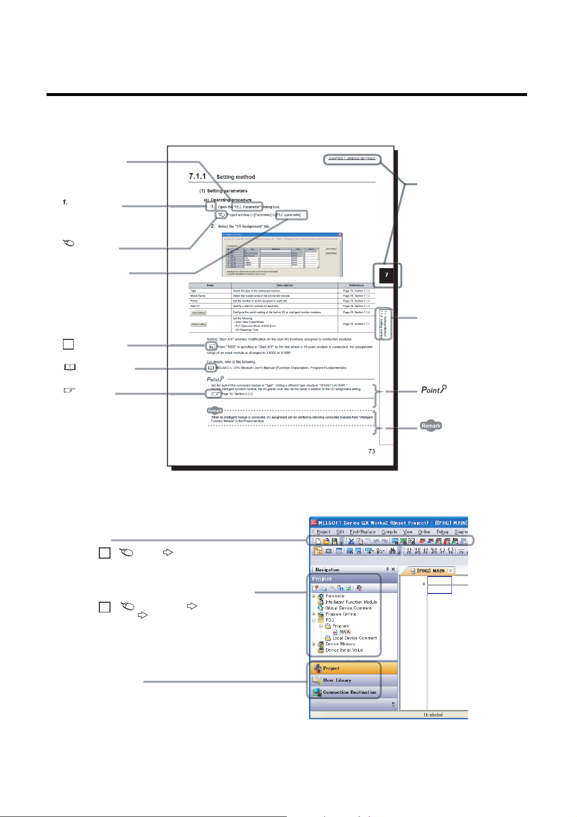
MANUAL PAGE ORGANIZATION
The section of
the current page is shown.
The chapter of
the current page is shown.
"" is used for
screen names and items.
[ ] is used for items
in the menu bar and
the project window.
shows operating
procedures.
shows reference
manuals.
shows notes that
requires attention.
shows mouse
operations.
*1
shows
reference pages.
shows setting or
operating examples.
Ex.
shows useful
information.
A window selected in the view selection area is displayed.
View selection area
[Online] [Write to PLC...]
Select [Online] on the menu bar,
and then select [Write to PLC...].
Project window
[Parameter]
[PLC Parameter]
Select [Project] from the view selection
area to open the Project window.
Menu bar
Ex.
Ex.
In the Project window, expand [Parameter] and
select [PLC Parameter].
In this manual, pages are organized and symbols are used as shown below.
The following page illustration is for explanation purpose only, and is different from the actual pages.
12
*1 The mouse operation example is provided below.
Page 15

TERMS
Unless otherwise specified, this manual uses the following terms.
Ter m Description
CC-Link IE Field Network A high-speed and large-capacity open field network that is based on Ethernet (1000BASE-T)
Master/local module
Ethernet adapter module The abbreviation for the NZ2GF-ETB CC-Link IE Field Network Ethernet adapter module.
Network module
External device A generic term for devices that send SLMP request messages to an Ethernet adapter module
Configuration tool A software package built in an Ethernet adapter module
GX Works2 The product name of the software package for the MELSEC programmable controllers
Master station
Local station
Remote I/O station A station that exchanges I/O signals (bit data) with the master station by cyclic transmission
Remote device station
Intelligent device station
Slave station
Reserved station A station reserved for future use. This station is not actually connected, but counted as a connected station.
Relay station
Cyclic transmission
Transient transmission
Data link A generic term for cyclic transmission and transient transmission
Routing
SLMP
Request message An SLMP message sent from an external device to an Ethernet adapter module
Response message An SLMP message sent from an Ethernet adapter module to an external device
Dedicated instruction An instruction that simplifies programming for using functions of intelligent function modules
Return A process of restarting data link when a station recovers from an error
Disconnection A process of stopping data link if a data link error occurs
Device A device (X, Y, W, or others) in an Ethernet adapter module
Link device A device (RX, RY, RWr, or RWw) in a module on CC-Link IE Field Network
A generic term for the CC-Link IE Field Network master/local modules: QJ71GF11-T2, QS0J71GF11-T2,
and LJ71GF11-T2
A generic term for the following modules:
• Module on CC-Link IE Field Network
• CC-Link IE Controller Network module
• Ethernet interface module
• MELSECNET/H module
• MELSECNET/10 module
A station that controls the entire network.
This station can perform cyclic transmission and transient transmission with all stations.
Only one master station can be used in a network.
A station that performs cyclic transmission and transient transmission with the master station and other local
stations. The station is controlled by programs in the CPU module or other equivalent modules on the
station.
A station that exchanges I/O signals (bit data) and I/O data (word data) with the master station by cyclic
transmission.
This station responds to a transient transmission request from another station.
A station that exchanges I/O signals (bit data) and I/O data (word data) with the master station by cyclic
transmission. This station responds to a transient transmission request from another station and also issues
a transient transmission request to another station.
A generic term for stations other than a master station: local station, remote I/O station, remote device
station, and intelligent device station
A station that includes two or more network modules. Data are passed through this station to stations on
other networks
A function by which data are periodically exchanged among stations on the same network using link devices
(RX, RY, RWw, and RWr)
A function of communication with another station, which is used when requested by a dedicated instruction
or GX Works2
A process of selecting paths for communication with other networks.
CC-Link IE Field Network requires communication paths to be preset using routing parameters to
communicate with stations on different networks.
An Ethernet adapter module does not require routing parameters. Communications with other networks are
performed according to the routing parameters set to the master station.
The abbreviation for Seamless Message Protocol.
This protocol is used to access an SLMP-compatible device or a programmable controller connected to an
SLMP-compatible device from an external device.
13
Page 16

Ter m Description
Bit data input from a slave station to the master station (For some areas in a local station, data are input in
Remote input (RX)
Remote output (RY)
Remote register (RWr)
Remote register (RWw)
SB (link special relay) Bit data that indicates the operating status and data link status of a module on CC-Link IE Field Network
SW (link special register) Word data that indicates the operating status and data link status of a module on CC-Link IE Field Network
Parameter memory
Buffer memory
RIRD
RIWT
the opposite direction.)
User's manual for the master/local module used
Bit data output from the master station to a slave station (For some areas in a local station, data are output
in the opposite direction.)
User's manual for the master/local module used
Word data input from a slave station to the master station (For some areas in a local station, data are input
in the opposite direction.)
User's manual for the master/local module used
Word data output from the master station to a slave station (For some areas in a local station, data are
output in the opposite direction.)
User's manual for the master/local module used
A flash ROM in an Ethernet adapter module, where the parameters of the Ethernet adapter module are
stored
A memory in an Ethernet adapter module, where data (such as Ethernet port information, setting values,
and monitoring values) are stored
The abbreviation for JP.RIRD and GP.RIRD.
This dedicated instruction is used in programs of the master/local module.
The abbreviation for JP.RIWT and GP.RIWT.
This dedicated instruction is used in programs of the master/local module.
14
Page 17
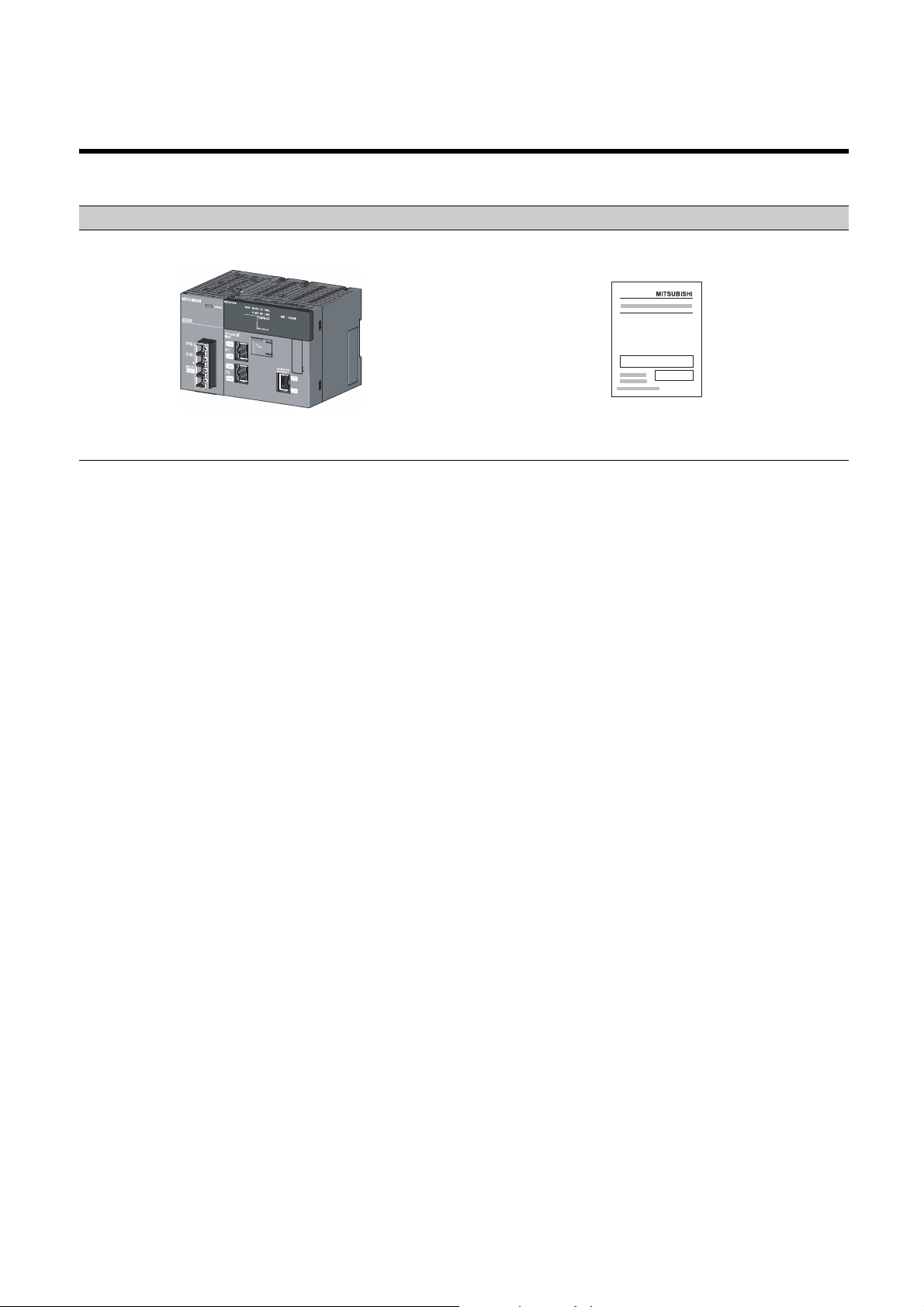
PACKING LIST
The following items are included in the package of this product. Before use, check that all the items are included.
NZ2GF-ETB
Ethernet adapter module Safety Guidelines (IB-0800463)
15
Page 18
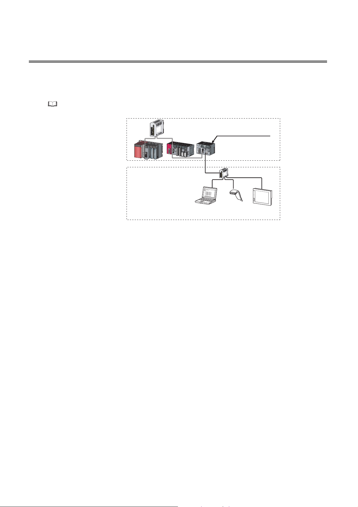
CHAPTER 1 ETHERNET ADAPTER MODULE
Configuration
tool
GOT
Switching hub
Ethernet
CC-Link
IE Field Network
Barcode
reader
Ethernet adapter module
The Ethernet adapter module connects external devices on the Ethernet network to CC-Link IE Field Network.
For details on CC-Link IE Field Network, refer to the following.
User's manual for the master/local module used
16
Page 19
CHAPTER 1 ETHERNET ADAPTER MODULE
Ethernet
Ethernet adapter module (station No. 1)
Master station (station No. 0) External device
CC-Link IE Field Network
(network No. 1)
On-demand data transmission
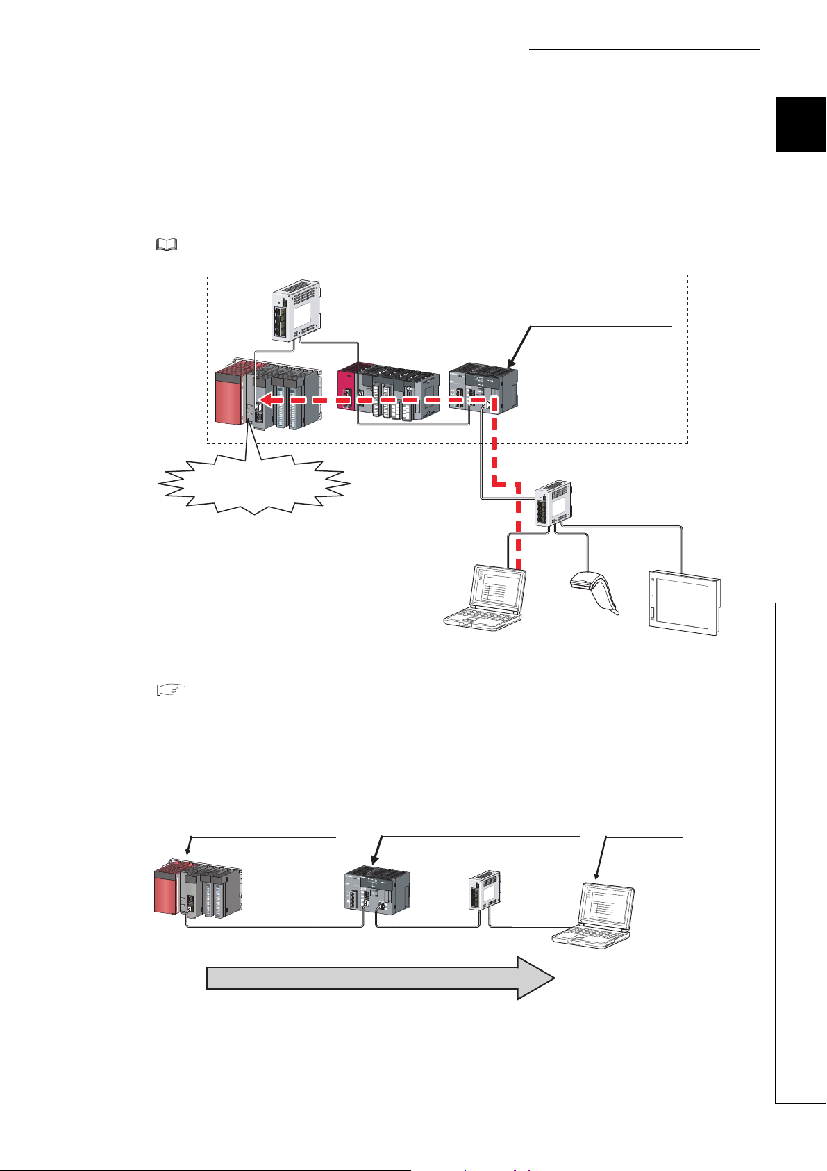
(1) Communication using SLMP
(a) Data of the programmable controller device can be read/written
Device data can be read or written from an external device to a module on the network where the Ethernet
adapter module is connected. Data reading and writing is also available to the devices of the Ethernet adapter
module. For details on SLMP, refer to the following.
SLMP Reference Manual
Ethernet adapter module
CC-Link
IE Field Network
Device reading
or
writing
Switching hub
SLMP
1
(b) The on-demand function enables data to be sent from the programmable controller
( Page 89, Section 7.2)
Issuing a send request from the CPU module to the Ethernet adapter module allows data to be sent to the
external device.
Events such as link start instruction and read instruction can be notified to an external device.
In addition, data can be simultaneously sent to all the external devices on Ethernet where the Ethernet adapter
module is also connected (broadcast communications).
17
Page 20
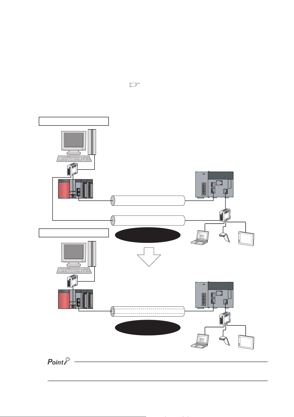
(2) Connection of MC protocol devices
Ethernet
Two networks were required.
CC-Link IE Field Network
Only CC-Link IE Field Network is
required to perform communications.
CC-Link IE Field Network
Ethernet communications (IP packet transfer)
When the IP packet transfer function is used
Conventional way
The message format of SLMP is the same as that of the QnA compatible 3E or 4E frame format of the MC
protocol. Therefore, external devices that support the MC protocol can be connected to CC-Link IE Field Network.
(3) Communications using the specified IP address over CC-Link IE Field Network
(IP packet transfer function) ( Page 105, Section 7.3)
With this function, communications using the specified IP address can be performed over CC-Link IE Field
Network. For example, a personal computer can communicate with the FTP server. Two networks of CC-Link IE
Field Network and Ethernet are not required, resulting in reduced wiring cost.
The IP packet transfer function allows an IP packet to be transferred from an external device to a request destination. An
Ethernet adapter module cannot be used as a request source or a request destination.
18
Page 21
CHAPTER 1 ETHERNET ADAPTER MODULE
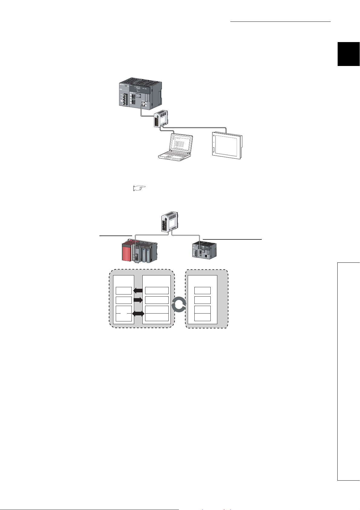
Ethernet adapter module
Master station
RWw
Master/local
module
CPU
module
X
Y
W
RX
RY
RWw
RWr
RX
RY
RWr
Ethernet
adapter module
(4) Connection to MELSOFT products or GOTs
The Ethernet adapter module can be also connected to MELSOFT products or GOTs.
Switching hub
MELSOFT
product
GOT
(5) Cyclic transmission ( Page 33, Section 3.2.1 (2))
Data can be periodically exchanged with the master station through link devices (RX, RY, RWr, and RWw).
1
19
Page 22
(6) Transient transmission
Command
REMFR
Device
Buffer memory
1234H
1234H
CPU module Master/local
module
Master station
Ethernet
adapter module
Transient transmission allows direct access from a master or local station to the devices or buffer memory of the
Ethernet adapter module.
Requests from the master or local station to the Ethernet adapter module are made with dedicated instructions.
( User's manual for the master/local module used)
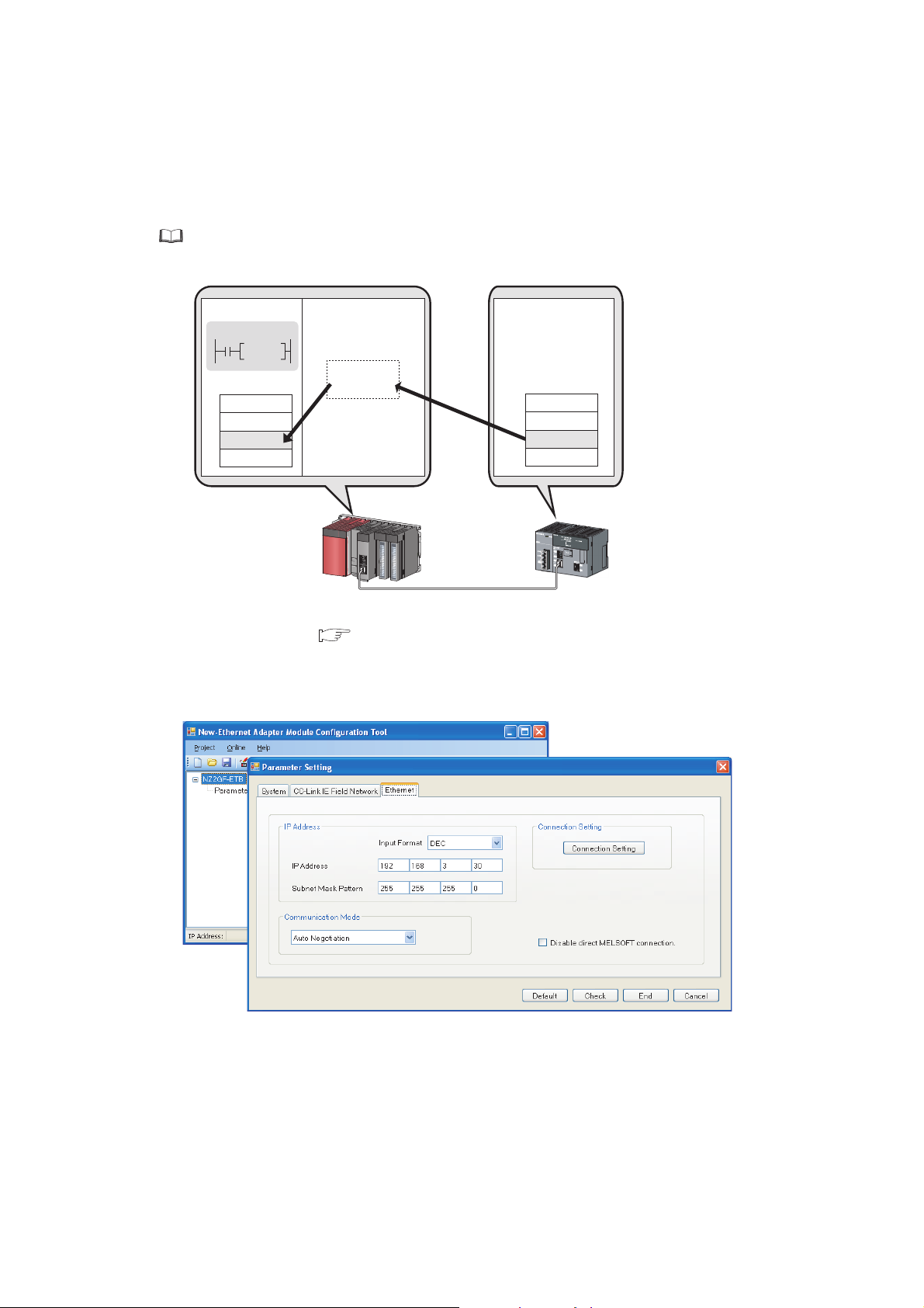
(7) Parameter setting ( Page 184, Section 10.3)
Parameters can be set in the configuration tool incorporated in the Ethernet adapter module. Therefore, there is
no need to create any configuration programs. The configuration tool will be started from a Web browser.
20
Page 23
CHAPTER 1 ETHERNET ADAPTER MODULE
The status of the entire CC-Link IE Field
Network can be monitored.
(8) Diagnostics
(a) CC-Link IE Field Network diagnostics
By connecting GX Works2 to a master/local module, the condition of the entire CC-Link IE Field Network can
be viewed on the CC-Link IE Field Network diagnostics dialog box. ( User's manual for the master/local
module used)
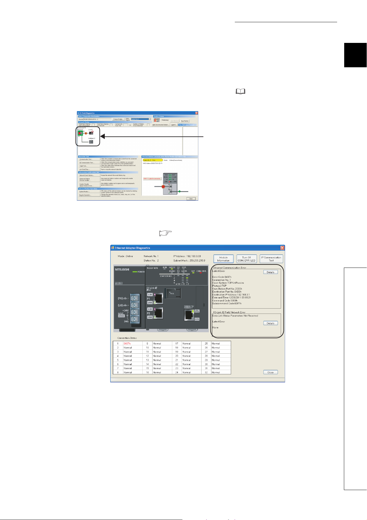
(b) Ethernet adapter diagnostics
In the Ethernet Adapter Diagnostics dialog box, the condition, such as an error occurred in communication with
an external device, can be checked. ( Page 198, Section 10.7)
1
21
Page 24
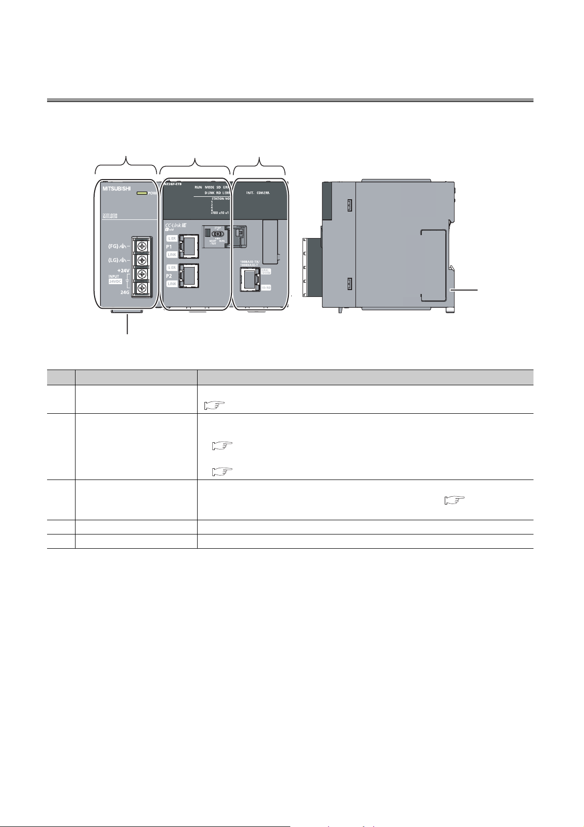
CHAPTER 2 PART NAMES
5)
4)
1) 2) 3)
This chapter describes the Ethernet adapter module parts and their names.
No. Name Description
1) Power supply part
2) CC-Link IE Field Network part
3) Ethernet part
4) Serial number display The serial number on the rating plate is indicated.
5) DIN rail hook This hook is used to mount the module to a DIN rail.
Power is supplied to the Ethernet adapter module through this part. (24VDC)
( Page 23, Section 2.1)
The Ethernet adapter module is connected to CC-Link IE Field Network at this part.
• The communication status of CC-Link IE Field Network is indicated with the LEDs.
( Page 24, Section 2.2 (1))
• The switch on this part is used for controlling the operation of the Ethernet adapter module.
( Page 26, Section 2.2 (2))
The Ethernet adapter module is connected to the Ethernet at this part.
The communication status of the Ethernet is indicated with the LEDs. ( Page 28, Section
2.3)
22
Page 25
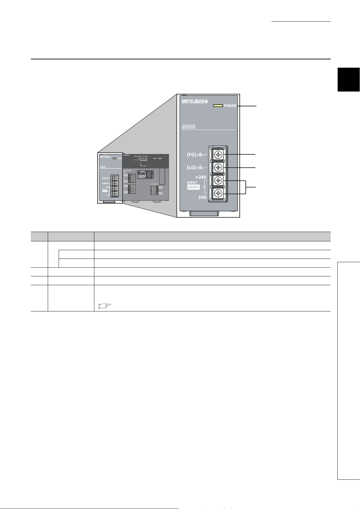
2.1 Power Supply Part
Respective names of the Ethernet adapter module's power supply part are shown below.
CHAPTER 2 PART NAMES
2
1)
2)
3)
4)
No. Name Part
POWER LED Indicates the operating status of the power supply part.
1)
2) FG terminal A ground terminal connected to the shield pattern on the printed circuit board (M3.5 screw)
3) LG terminal A terminal grounded to a power filter (M3.5 screw)
4)
On (green) Normally operating.
Off No power input, power failure, or hardware failure
Power input
terminal
Terminals for power input. (M3.5 screws)
For the specifications of the power supply to be connected, refer to "Performance specifications of each part."
( Page 31, Section 3.2.1 (1))
2.1 Power Supply Part
23
Page 26
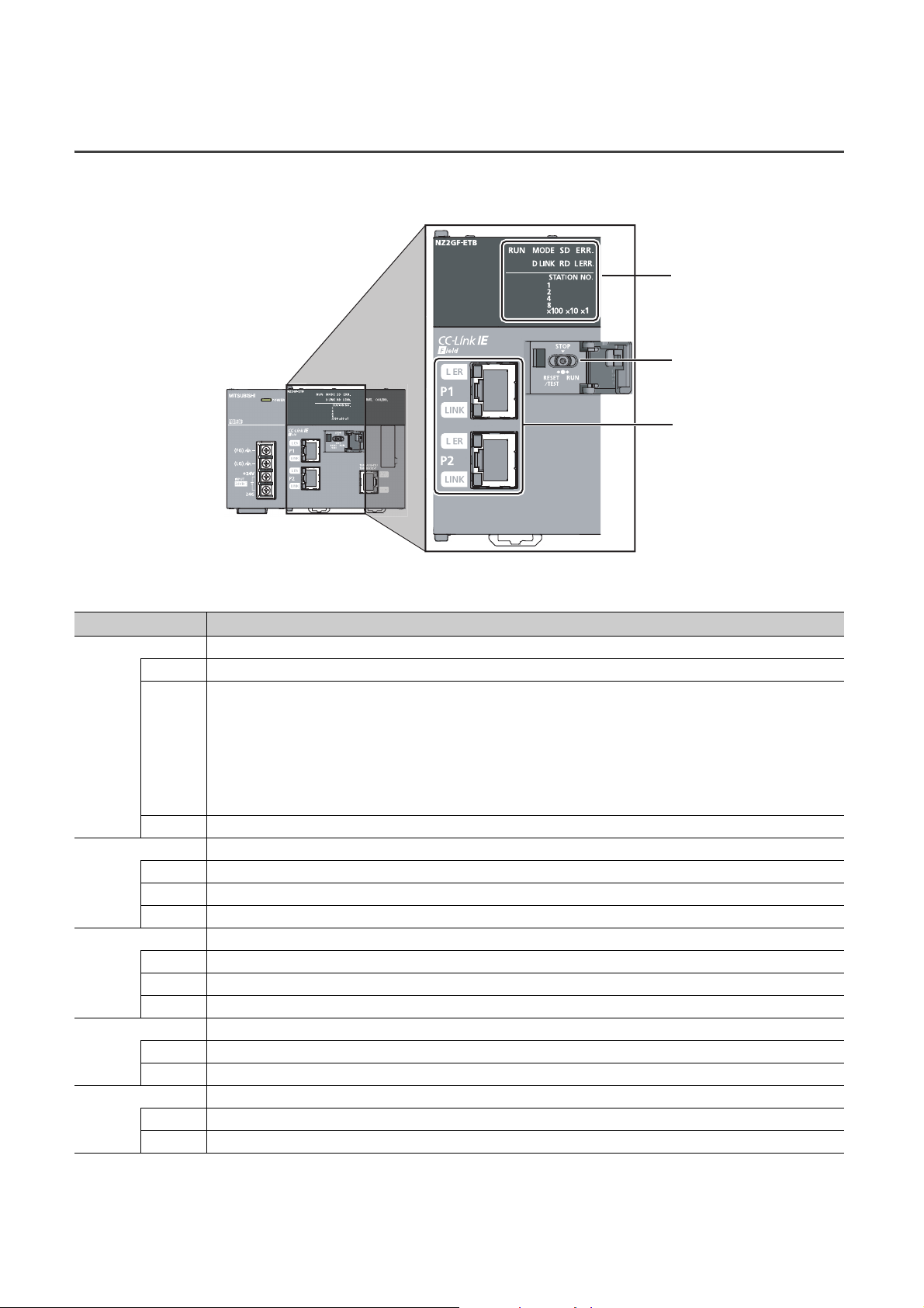
2.2 CC-Link IE Field Network Part
(1)
(2)
(3)
Respective names of the Ethernet adapter module's CC-Link IE Field Network part are shown below.
(1) LEDs
Name Description
RUN LED Indicates the operating status.
On Normally operating. (RUN status)
Normally operating. (STOP status)
• The Ethernet adapter module's switch is set to STOP. (Data transfer among the Ethernet adapter module
devices is stopped.)
Flashing
Off A hardware failure or a watchdog timer error has occurred.
MODE LED Indicates the mode.
On Online mode
Flashing Test mode
Off Offline mode
D LINK LED Indicates the data link status of CC-Link IE Field Network.
On Data link in operation (cyclic transmission in progress)
Flashing Data link in operation (cyclic transmission stopped)
Off Data link not in operation (disconnected) or the module is in offline mode.
SD LED Indicates the data sending status on CC-Link IE Field Network.
On Data being sent
Off No data being sent
RD LED Indicates the data receiving status on CC-Link IE Field Network.
On Data being received
Off No data being received
• The master station is in the STOP status. (Data transfer among the Ethernet adapter module devices is
continued.)
• A remote STOP request is being received.
• The Ethernet adapter module stopped due to an error (except a watchdog timer error).
24
Page 27
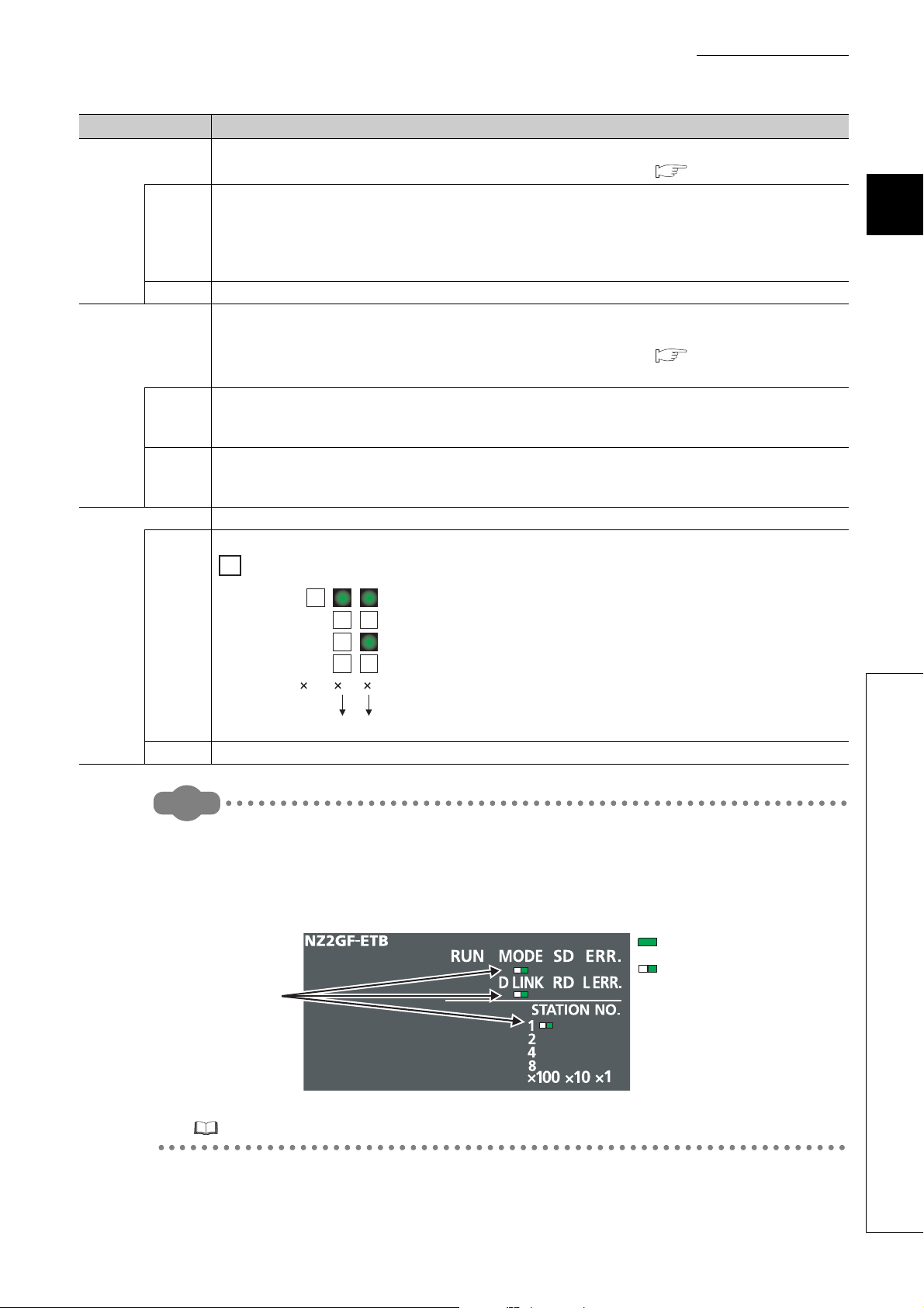
Remark
Name Description
110100
10 5+=15
1
2
8
4
ERR. LED
On
Off Normally operating.
L ERR. LED
On
Off
STATION NO. Indicates the station number of the Ethernet adapter module.
Indicates the error status of the Ethernet adapter module.
The error details can be checked by the CC-Link IE Field Network diagnostics. ( Page 141, Section 9.2.1)
One of the following errors occurred in the Ethernet adapter module.
• Multiple modules with the same station number exist on CC-Link IE Field Network.
• Network parameters for CC-Link IE Field Network is corrupted. Or, there is an error in the reserved station
setting, the number of connected stations, or the network number setting.
• There is an error in the network parameter settings for the Ethernet adapter module.
Indicates the error status of the received data and the line. When this LED is on, check the L ER LED for "P1" or
"P2" to see on which port the error was detected.
The error details can be checked by the CC-Link IE Field Network diagnostics. ( Page 141, Section 9.2.1)
This LED automatically turns off when the module has received normal data and loopback is completed.
• The Ethernet adapter module has received abnormal data.
• The Ethernet adapter module is performing loopback (only the Ethernet adapter module with a serial number
(first five digits) of "12102" or later).
• The Ethernet adapter module has received normal data.
• The Ethernet adapter module does not perform loopback (only the Ethernet adapter module with a serial number
(first five digits) of "12102" or later).
Indicates the station number.
CHAPTER 2 PART NAMES
2
Ex.
Station No.15
On
Off The station number has not been set.
● LED indication during line test execution
While a line test is being performed from the master station, the following LEDs are flashing.
•MODE LED
• D LINK LED
• ×100 LED
Flashing
: On
: Flashing
2.2 CC-Link IE Field Network Part
For execution of the line test, refer to the following.
User's manual for the master/local module used
25
Page 28
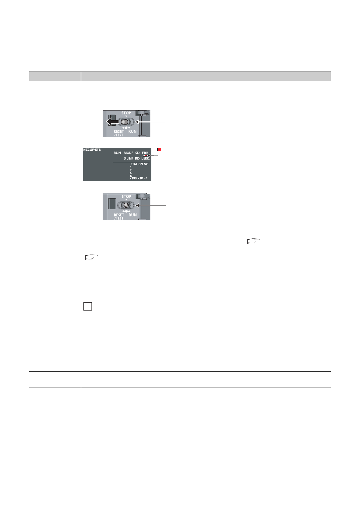
(2) Switch
1. Shift the switch to RESET/TEST for one
second or longer.
Hold the switch and do not release it.
2. Confirm that the ERR. LED flashes
several times and then turns off.
3. Set the switch back to the STOP
position.
The switch will automatically return to the
STOP position when released.
Flashes several times
and then turns off
: Flashing
With this switch, the operation of the Ethernet adapter module can be controlled.
Name Description
The Ethernet adapter module can be reset by the following method.
Set the switch with your fingertip. Using a tool such as a screwdriver may damage the switch.
Switch
RESET/TEST
Switch
You can also switch the Ethernet adapter module to the test mode and reset the parameters to default values.
For switching to the test mode, refer to "Testing the Module Before Wiring." ( Page 57, Section 6.3)
For resetting the parameters to default values, refer to "Resetting Parameters to Factory Default Values."
( Page 222, Appendix 6)
Transfer between the link devices (cyclic data from the master station) and the devices of the Ethernet adapter
module is stopped. (Transfer is stopped while cyclic transmission with the master station is continued.)
This transfer stop can prevent the data exchanged between an external device and the Ethernet adapter module
from being sent to the master and local stations. The STOP switch is used for a purpose, such as debugging
between the Ethernet adapter module and external devices.
STOP
RUN
26
Ex.
Debugging communication data with an external device using the STOP switch
*1
*1 Even if the switch is set to "STOP", the Ethernet adapter module is shown to be in the cyclic transmission status at the
(1) Set the switch to "STOP."
(2) Data transfer between the link devices and devices of the Ethernet adapter module is stopped, and the
Ethernet adapter module is separated from the master station control.
(3) Check if communications are normally performed between the Ethernet adapter module and an external
device. Because transfer is stopped, data exchanged between the Ethernet adapter module and the external
device will not be sent to the master and local stations.
(4) After checking the above, write the parameters to the Ethernet adapter module and start the system
operation.
Cyclic transmission starts between the Ethernet adapter module and the master station. (Data communication
between the Ethernet adapter module and external devices is performed regardless of the switch status.)
master station.
Page 29
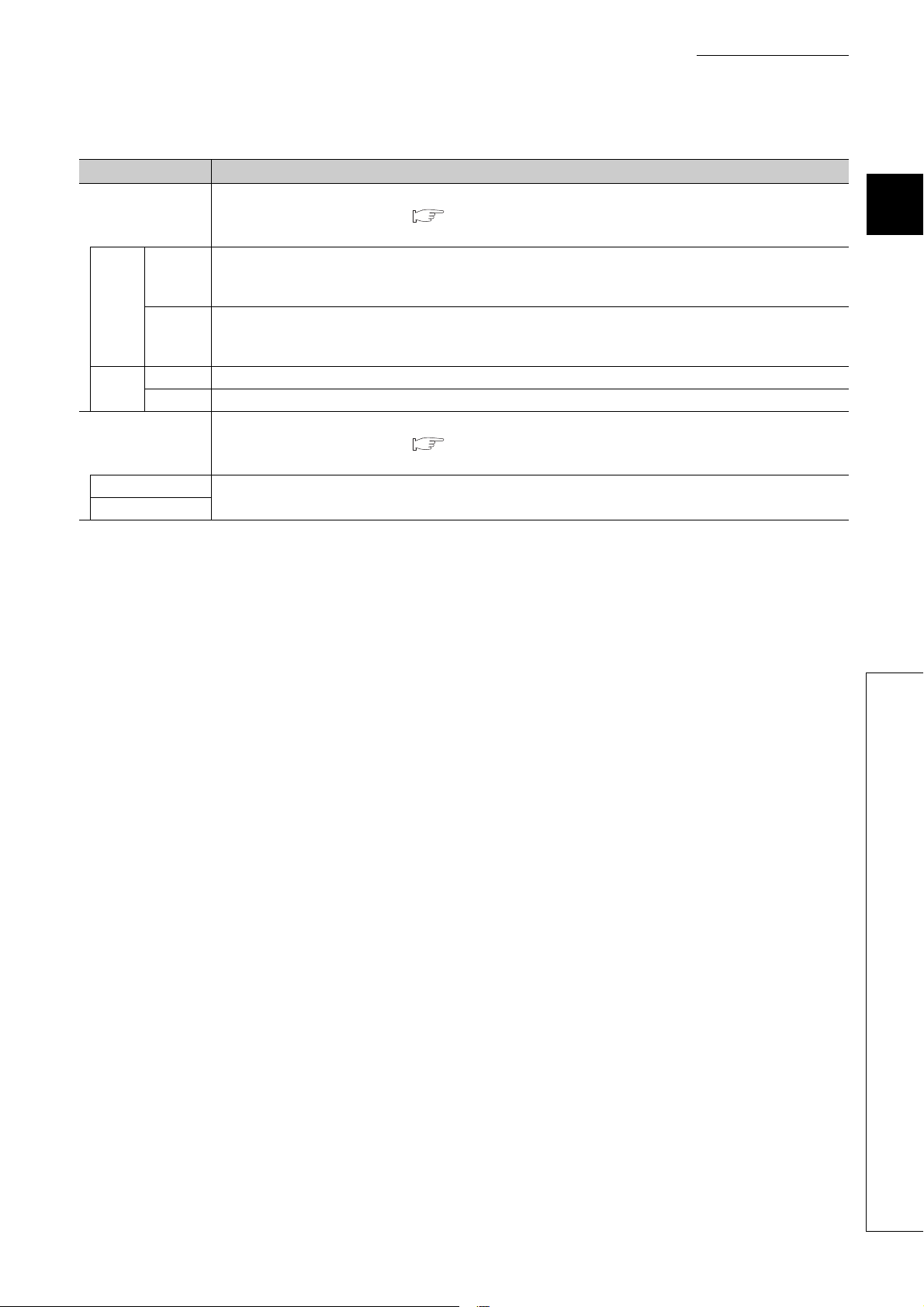
(3) Connectors
Name Description
The PORT1 connector for connecting to CC-Link IE Field Network. (RJ45 connector)
P1
L ER
LED
LINK
LED
P2
L ER LED
LINK LED
On
Off
On Linkup in progress
Off Linkdown in progress
Connect an Ethernet cable to this. ( Page 61, Section 6.4.2)
There are no restrictions on the connection order of the cables for the "P1" and "P2" connectors.
• The Ethernet adapter module has received abnormal data.
• The Ethernet adapter module is performing loopback (only the Ethernet adapter module with a serial number
(first five digits) of "12102" or later).
• The Ethernet adapter module has received normal data.
• The Ethernet adapter module does not perform loopback (only the Ethernet adapter module with a serial number
(first five digits) of "12102" or later).
The PORT2 connector for connecting to CC-Link IE Field Network. (RJ45 connector)
Connect an Ethernet cable to this. ( Page 61, Section 6.4.2)
There are no restrictions on the connection order of the cables for the "P1" and "P2" connectors.
(Same as the "P1" connector)
CHAPTER 2 PART NAMES
2
2.2 CC-Link IE Field Network Part
27
Page 30
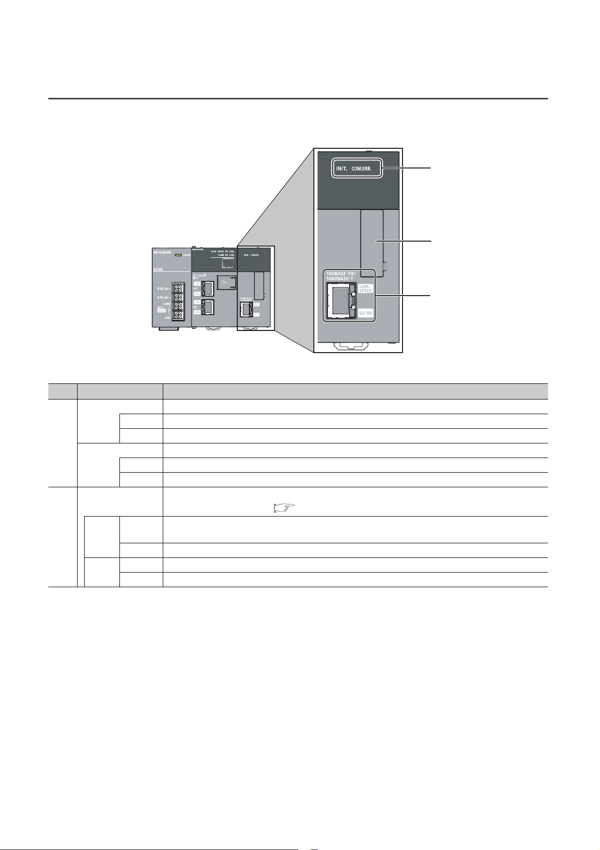
2.3 Ethernet Part
This section describes the names of the Ethernet adapter module's Ethernet part.
*1 Do not remove this sticker since it is used for maintenance.
1)
*1
2)
No. Name Description
INIT. LED Indicates the initial processing status.
On Initial processing completed.
1)
COM.ERR. LED Indicates the Ethernet communication status.
Ethernet port
2)
LINK/
SPEED
SD/RD
Off Initial processing not completed.
On An error occurred in Ethernet communication.
Off Normal Ethernet communication
Connector for Ethernet connection. (RJ45 connector)
Connects an Ethernet cable. ( Page 61, Section 6.4.2)
On
Off Linkdown in progress
On Data being sent or received in Ethernet communication
Off No data transfer in Ethernet communication
• Green: Linkup in progress at 1Gbps
• Orange: Linkup in progress at 100Mbps
28
Page 31

CHAPTER 3 SPECIFICATIONS
This chapter describes the specifications of the Ethernet adapter module.
3.1 General Specifications
Item Specification
Operating ambient
temperature
Storage ambient
temperature
Operating ambient
humidity
Storage ambient
humidity
Compliant with
Vibration resistance
Shock resistance
Operating atmosphere No corrosive gases
Operating altitude
Installation location Inside a control panel
Overvoltage category
Pollution degree
Equipment class Class I
*1
*3
*1 Do not use or store the Ethernet adapter module under pressure equivalent to the atmospheric pressure of an elevation
of 0m or higher. Doing so may cause malfunction. When applying pressure to the module, please consult your local
Mitsubishi representative.
*2 This indicates the section of the power supply to which the equipment is assumed to be connected between the public
power distribution network and the machinery within premises.
Category II applies to equipment for which electric power is supplied from fixed facilities. The surge voltage withstand
level for up to the rated voltage of 300V is 2500V.
*3 This index indicates the degree to which conductive material is generated in terms of the environment in which the
equipment is used.
At pollution level 2, only non-conductive pollution occurs. A temporary conductivity caused by condensing must be
expected occasionally.
JIS B 3502 and
IEC 61131-2
Compliant with JIS B 3502 and IEC 61131-2 (147m/s
*2
Under
intermittent
vibration
Under
continuous
vibration
5 to 95%RH, non-condensing
Frequency
5 to 8.4Hz 3.5mm 10 times each in
8.4 to 150Hz
5 to 8.4Hz 1.75mm
8.4 to 150Hz
0 to 55°C
-25 to 75°C
Constant
acceleration
9.8m/s
4.9m/s
0 to 2000m
II or lower
2 or lower
CHAPTER 3 SPECIFICATIONS
Half amplitude Sweep count
2
2
2
, 3 times each in X, Y, and Z directions)
X, Y, and Z
directions
3
3.1 General Specifications
For compliance with the EMC directive, refer to "EMC and Low Voltage Directives" in this manual.
( Page 224, Appendix 8)
29
Page 32

3.2 Performance Specifications
The following describes the performance specifications of the Ethernet adapter module.
Item Specification
X
Y
Number of device points
Number of writes to the parameter memory Up to 100000 times
Clock function (for display of data such as the
date and time at which an error occurred)
Internal current consumption (24VDC) 0.6A
External dimensions
Weight 0.7kg
W
SB 8192 points, 1KB
SW 8192 points, 16KB
SM 2048 points, 256 bytes
SD 2048 points, 4KB
H90mm
W135mm
D109mm
8192 points, 1KB
(X0 to X1FFF are assigned to RX0 to RX1FFF.)
8192 points, 1KB
(Y0 to Y1FFF are assigned to RY0 to RY1FFF.)
8192 points, 16KB
(1024 points of W0 to W3FF are assigned to RWw0 to RWw3FF.
1024 points of W1000 to W13FF are assigned to RWr0 to RWr3FF.)
Year, month, date, hour, minute, and second (with automatic leap year detection)
When connected to a network, the clock is periodically synchronized with the clock in the
CPU module on the master station via the network. (Initial value: 2000/1/1 00:00:00)
If the Ethernet adapter module is powered off and then on, the clock will restart at the time
the power was turned off. (The clock does not run while the power is off.)
Therefore, the date and time of an error that occurred during initial processing may be
different from the actual date and time.)
30
Page 33

3.2.1 Performance specifications of each part
The performance specifications of each part of the Ethernet adapter module are described below.
CHAPTER 3 SPECIFICATIONS
Power supply
part
CC-Link IE Field
Network part
(1) Power supply part
Item Specification
Input voltage
( Page 32, Section 3.2.1 (1) (a))
Current consumption 0.6A
Inrush current
( Page 32, Section 3.2.1 (1) (b))
Allowable momentary power failure time
( Page 32, Section 3.2.1 (1) (c))
Withstand voltage
Insulation resistance
Noise immunity
Operation status indicator LEDs (Normal: On (green), Error: Off)
Fuse Built-in (not replaceable)
Terminal screw size M3.5
Applicable wire size
Applicable solderless terminal
Applicable tightening torque 0.66 to 0.89N•m
24VDC (-35% to +30%)
100A, 1ms or less
10ms or less
510V AC/min (Altitude: 0 to 2,000m)
Between inputs/LG and outputs/FG
10M or higher by 500VDC insulation resistance tester
(Between inputs/LG and outputs/FG, inputs and LG, outputs and FG)
• By noise simulator of 500Vp-p noise voltage, 1µs noise width, and 25 to 60 Hz noise
frequency
• Noise voltage IEC 61000-4-4, 2kV
0.75 to 2 mm
RAV1.25-3.5, RAV2-3.5, 0.8mm or less in thickness
Two solderless terminals can be connected to one terminal.
2
Ethernet
part
3
3.2 Performance Specifications
3.2.1 Performance specifications of each part
31
Page 34

(a) Input voltage
Input voltage is a voltage at which the power supply part operates normally. If it is outside the specified range,
the Ethernet adapter module may detect an error and stop its operation.
(b) Inrush current
Inrush current is a large current that instantaneously flows into a circuit immediately after power is applied.
Reapplying input power after power-off may cause an inrush current that exceeds the specified value. Allow 5
seconds or more before reapplying input power.
Also, select appropriate fuses or breakers for external circuits, considering the possibility of meltdown, sensing
property, and other items shown in this section.
(c) Allowable momentary power failure time
If a momentary power failure occurs, the system detects an input voltage failure and stops its operation.
Allowable momentary power failure time is the period of time that the system can continue its operation after
power is restored.
If a momentary stop exceeding the allowable momentary power failure time occurs, the operation will be
continued by the load of the power supply part, or will be initially started. When the operation is continued, the
operational behavior is the same as that for the momentary stop within the allowable momentary power failure
time.
32
Page 35

(2) CC-Link IE Field Network part
Item Specification
RWw 8192 points, 16KB
Maximum link points per
network
Maximum link points per
station
Station type Intelligent device station
Station No. 1 to 120
Network No. 1 to 239
Communication method Token passing method
Communication speed 1Gbps
Transmission path
Connection cable
RWr 8192 points, 16KB
RX 16384 points, 2KB
RY 16384 points, 2KB
RWw 1024 points, 2KB
RWr 1024 points, 2KB
RX 2048 points, 256 bytes
RY 2048 points, 256 bytes
Line or star topology (Coexistence of line topology and star topology is possible.), ring
topology
An Ethernet cable that meets the 1000BASE-T standard:
Category 5e or higher, (Double shielded/STP) Straight cable
(
Page 48, Section 5.2.1)
CHAPTER 3 SPECIFICATIONS
3
Maximum station-to-station distance
Overall cable distance
Number of cascade connections Up to 20
Up to 100m (compliant with ANSI/TIA/EIA-568-B (Category 5e)) (
6.4.4 (7))
Line topology: 12000m (when connecting 1 master station and 120 slave stations)
Star topology: Depends on the system configuration
Ring topology: 12100m (when connecting 1 master station and 120 slave stations)
Page 65, Section
3.2 Performance Specifications
3.2.1 Performance specifications of each part
33
Page 36

(3) Ethernet part
Item Specification
For users 32
Number of
connections
Own Station Port No.
Number of simultaneously connectable
modules
Communication speed 1Gbps or 100Mbps
Communication mode Full- or Half-duplex
Transmission system Base band
Connection cable
Maximum distance between switching hub
and node
Number of cascade connections Up to 20
For auto-open 1
For MELSOFT
connection
For 1Gbps
For 100Mbps
*2
3 (TCP connection: 1
1025 to 4999, 5011 to 65534 (0401
Up to 32
An Ethernet cable that meets the 1000BASE-T standard:
Category 5e or higher, (Double shielded/STP) Straight cable
Page 48, Section 5.2.2 (1))
(
An Ethernet cable that meets the 100BASE-TX standard:
Category 5 or higher, (STP) Straight cable
(
Page 48, Section 5.2.2 (1))
Up to 100m
*1
, UDP connection: 1, Direct connection: 1)
to 1387H, 1393H to FFFEH)
H
*1 To use two or more TCP connections for a MELSOFT Connection, user connections can be assigned to MELSOFT
Connection. (
*2 Use of double shielded cables is recommended in a high noise environment.
● When connected to a switching hub, the Ethernet adapter module detects and sets 1000BASE-T or 100BASE-TX and
full-or half- duplex communication mode according to the switching hub. When the connected switching hub does not
support the auto-negotiation function, set the switching hub to the half-duplex communication mode.
● The operation of the following connections is not guaranteed. Check the operation at the user's discretion before use.
• Connections using the Internet (public line)
(Internet connection services by Internet service providers or telecommunications carriers)
• Connections using firewall devices
• Connections using broadband routers
Page 191, Section 10.3.3 (1))
34
Page 37

(a) Communication specifications for TCP connection
Ex.
• Number of resends and resend interval
If the Ethernet adapter module sent a message to an external device and after that did not receive an ACK
from the external device, it will resend the message at the intervals shown below.
Item Specification
Number of resends Up to 3 times
Up to 64 seconds (Varies depending on the line status.)
If the resend fails, the amount of time is doubled. (The maximum value is 64
seconds.)
Resend interval
When the interval for the first resend is 20 seconds;
1st: 20s, 2nd: 40s, 3rd: 64s
If the Ethernet adapter module fails to receive an ACK response from the external device even when it
resends data as many times as the number of resends, it regards that there is no external device, causing
disconnection.
When the connection is disconnected, send a connection establishment request from the external device,
reestablish a connection, and resend a request message.
CHAPTER 3 SPECIFICATIONS
3
• Alive check by KeepAlive
The Ethernet adapter module performs alive check by KeepAlive.
The Ethernet adapter module sends an alive check message in 5 seconds after receiving the last
message from an external device. If no response is returned from the external device for 5 seconds, the
module resends the alive check message. The module resends the message for 7 times at intervals of 5
seconds.
If no response is received for 45 seconds from the last message reception from the external device, the
Ethernet adapter module will close the connection. Allow 45 seconds or longer before opening the same
connection again.
When the external device does not support the TCP KeepAlive function, the connection may be closed.
• Connection establishment request
When a connection establishment request is sent from an external device to the port of the Ethernet
adapter module, where a connection has been already established, the Ethernet adapter module will not
respond. Therefore, if no response is returned even after a connection establishment request is sent to the
Ethernet adapter module, check if the specified port number is correct.
3.2 Performance Specifications
3.2.1 Performance specifications of each part
35
Page 38

3.3 List of the Functions
This section lists the functions of the Ethernet adapter module.
(1) Communications with an external device
Function Description Refer to
Device data can be read or written from an external device to a
Communications from
an external device
Communications
using SLMP
Communication using the specified IP
address over CC-Link IE Field Network
(IP packet transfer function)
Connection to MELSOFT products or
GOTs
Communications from
a CPU module
(on-demand function)
module on the network where the Ethernet adapter module is
connected. Data also can be read or written from/to the Ethernet
adapter module.
Issuing a send request from the CPU module to the Ethernet
adapter module allows data to be sent to the external device.
Events such as link start instruction and read instruction can be
notified to an external device.
In addition, data can be simultaneously sent to all the external
devices on Ethernet where the Ethernet adapter module is also
connected (broadcast communications).
With this function, communications using the specified IP address
can be performed over CC-Link IE Field Network. For example, a
personal computer connected to the Ethernet part can
communicate with another personal computer connected to a Built-
in Ethernet port QCPU.
Two networks of CC-Link IE Field Network and Ethernet are not
required, resulting in reduced wiring cost.
The Ethernet adapter module can be also connected to MELSOFT
products or GOTs.
Page 66, Section 7.1
Page 89, Section 7.2
Page 105, Section 7.3
(2) CC-Link IE Field Network communications
Function Description Refer to
Cyclic transmission
Transient transmission
Data can be periodically exchanged with the master station through
link devices (RX, RY, RWr, and RWw).
The devices or buffer memory of the Ethernet adapter module can
be directly accessed from the master or local station.
Requests from the master or local station to the Ethernet adapter
module are made with dedicated instructions.
(3) Other functions
Function Description Refer to
Device/buffer memory batch monitor
Ethernet adapter diagnostics
The values in the devices and buffer memory of the Ethernet
adapter module can be monitored.
Information such as the latest error that occurred in the Ethernet
adapter module and the status of the communications with an
external device can be checked.
Page 66, Section 7.1
Page 196, Section 10.6
Page 198, Section 10.7
36
Page 39

CHAPTER 3 SPECIFICATIONS
3.4 Buffer Memory List
The buffer memory is used for exchanging data between the Ethernet adapter module and a master/local module or an
external device.
The contents of the buffer memory return to the default state (initial values) when the system is powered off or reset.
Address
(Decimal
(Hexadecimal))
0
)
(0
H
1
)
(1
H
2
)
(2
H
3 to 15
to FH)
(3
H
16 to 18
to 12H)
(10
H
19
)
(13
H
20 to 21
to 15H)
(14
H
22 to 25
to 19H)
(16
H
26 to 28
to 1CH)
(1A
H
29
)
(1D
H
30 to 31
to 1FH)
(1E
H
32 to 33
to 21H)
(20
H
34 to 35
to 23H)
(22
H
36
)
(24
H
37
)
(25
H
38
)
(26
H
39 to 47
to 2FH)
(27
H
48
)
(30
H
49 to 767
to 2FFH)
(31
H
768
)
(300
H
Name
Module LED information
Module operation area
System area
Own station information
(PORT1 and PORT2)
System area
Own station information
(Ethernet port)
System area
Own station information
(Parameters)
System area
Ethernet port operation area
(area for initial processing)
Station No. LED information
Ethernet port LED information
Own station MAC address Read
System area
Own station IP address 0 Read
Own station MAC address Read
System area
Own station IP address 0
Own station subnet mask 0
Mode 0 Read
Network No. 0 Read
Station No. 0 Read
System area
Function check area
Initial processing error code 0 Read
*1
Initial
value
0001
Read/Write Refer to
Read
0
Read
Read
H
Read
Page 201,
Appendix 1.1 (1)
Page 201,
Appendix 1.1 (2)
Page 201,
Appendix 1.1 (3)
Page 202,
Appendix 1.2 (1)
Page 202,
Appendix 1.2 (1)
Page 202,
Appendix 1.2 (2)
Page 202,
Appendix 1.2 (2)
Page 202,
Appendix 1.2 (3)
Page 202,
Appendix 1.2 (3)
Page 203,
Appendix 1.3 (1)
3
3.4 Buffer Memory List
37
Page 40

Address
(Decimal
(Hexadecimal))
769 to 783
to 30FH)
(301
H
784
)
(310
H
785
)
(311
H
786
)
(312
H
787
)
(313
H
788
)
(314
H
789
)
(315
H
790 to 791
to 317H)
(316
H
792
)
(318
H
793
)
(319
H
794 to 795
to 31BH)
(31A
H
796 to 799
to 31FH)
(31C
H
800 to 1295
(320
to 50FH)
H
1296
)
(510
H
1297
)
(511
H
1298
)
(512
H
1299
)
(513
H
1300
)
(514
H
1301
)
(515
H
1302 to 1303
to 517H)
(516
H
1304
)
(518
H
1305
)
(519
H
1306 to 1307
to 51BH)
(51A
H
Name
Initial
value
Read/Write Refer to
System area
Open system 1
Protocol 0
Read
Communication data code 1
Page 203,
Appendix 1.3 (2)
Own Station Port No. 0
Ethernet port operation area
(Connection information area
TCP connection system 0
Read
Connection status 0
Page 203,
Appendix 1.3 (2)
No.1)
System area
Latest error code 0 Read
Destination port No. 0 Read
Page 203,
Appendix 1.3 (2)
Destination IP address 0 Read
System area
Ethernet port operation area
(Connection information area
No.2 to No.32)
Same as Connection information area No.1
Page 204,
Appendix 1.3 (3)
Open system 3
Ethernet port operation area
(Auto-open UDP port area)
Protocol 1
Read
Communication data code 0
Own Station Port No.
1388
H
System area
Connection status 0 Read
Page 204,
Appendix 1.3 (4)
Page 204,
Appendix 1.3 (4)
System area
Latest error code 0
Destination port No. 0
Read
Page 204,
Appendix 1.3 (4)
Destination IP address 0
38
Page 41

CHAPTER 3 SPECIFICATIONS
Address
(Decimal
(Hexadecimal))
1308 to 1311
to 51FH)
(51C
H
1312
)
(520
H
1313
)
(521
H
1314
)
(522
H
1315
)
(523
H
1316
)
(524
H
1317
)
(525
H
1318 to 1319
to 527H)
(526
H
1320
)
(528
H
1321
)
(529
H
1322 to 1323
to 52BH)
(52A
H
1324 to 1327
to 52FH)
(52C
H
1328
)
(530
H
1329
)
(531
H
1330
)
(532
H
1331
)
(533
H
1332
)
(534
H
1333
)
(535
H
1334 to 1335
to 537H)
(536
H
1336
)
(538
H
1337
)
(539
H
1338 to 1339
to 53BH)
(53A
H
1340 to 1343
to 53FH)
(53C
H
Name
Initial
value
Read/Write Refer to
System area
System area
Protocol 1
Communication data code 0
Own Station Port No.
1389
Read
H
Page 205,
Appendix 1.3 (5)
System area
Ethernet port operation area
(MELSOFT application
communication port (UDP/IP)
Connection status 0 Read
Page 205,
Appendix 1.3 (5)
area for the system)
System area
Latest error code 0
Destination port No. 0
Read
Page 205,
Appendix 1.3 (5)
Destination IP address 0
System area
Open system 0
Protocol 0
Ethernet port operation area
(MELSOFT application
communication port (TCP/IP)
area for the system)
Communication data code 0
Own Station Port No.
138A
TCP connection system 0
Connection status 0
Read
H
Page 206,
Appendix 1.3 (6)
System area
Latest error code 0
Destination port No. 0
Read
Page 206,
Appendix 1.3 (6)
Destination IP address 0
System area
3
3.4 Buffer Memory List
39
Page 42

Address
(Decimal
(Hexadecimal))
1344
)
(540
H
1345
)
(541
H
1346
)
(542
H
1347
)
(543
H
1348
)
(544
H
1349
)
(545
H
1350 to 1351
to 547H)
(546
H
1352
)
(548
H
1353
)
(549
H
1354 to 1355
to 54BH)
(54A
H
1356 to 1359
to 54FH)
(54C
H
1360
)
(550
H
1361
)
(551
H
1362
)
(552
H
1363
)
(553
H
1364
)
(554
H
1365
)
(555
H
1366 to 1367
to 557H)
(556
H
1368
)
(558
H
1369
)
(559
H
1370 to 1371
to 55BH)
(55A
H
1372 to 2048
to 800H)
(55C
H
Name
Initial
value
Read/Write Refer to
Open system 3
Ethernet port operation area
(Direct MELSOFT connection
port)
Protocol 1
Read
Communication data code 0
Own Station Port No.
1390
H
System area
Connection status 0 Read
Page 207,
Appendix 1.3 (7)
Page 207,
Appendix 1.3 (7)
System area
Latest error code 0
Destination port No. 0
Read
Page 207,
Appendix 1.3 (7)
Destination IP address 0
System area
Open system 3
Protocol 1
Page 208,
Appendix 1.3 (8)
Page 208,
Appendix 1.3 (8)
Ethernet port operation area
(Connection port for the
configuration tool)
Read
Communication data code 0
Own Station Port No.
1392
H
System area
Connection status 0 Read
System area
Latest error code 0
Destination port No. 0
Read
Page 208,
Appendix 1.3 (8)
Destination IP address 0
System area
40
Page 43

CHAPTER 3 SPECIFICATIONS
Address
(Decimal
(Hexadecimal))
2049
)
(801
H
2050
)
(802
H
2051 to 2063
to 80FH)
(803
H
2064
)
(810
H
2065
)
(811
H
2066
)
(812
H
2067
)
(813
H
2068
)
(814
H
2069
)
(815
H
2070 to 2071
to 817H)
(816
H
2072 to 2075
to 81BH)
(818
H
2076
)
(81C
H
2077
)
(81D
H
2078 to 2079
to 81FH)
(81E
H
2080 to 3087
to C0FH)
(820
H
3088 to 3327
to CFFH)
(C10
H
3328
)
(D00
H
3329 to 5375
to 14FFH)
(D01
H
5376 to 5377
to 1501H)
(1500
H
5378 to 5631
to 15FFH)
(1502
H
Name
Error count 0
Ethernet port error log area
Error log write pointer 0
Initial
value
Read/Write Refer to
Page 209,
Read
Appendix 1.4 (1)
Page 209,
Appendix 1.4 (2)
System area
Error code 0
Connection No. 0
Open system 0
Read
Protocol 0
Page 209,
Appendix 1.4 (3)
Own Station Port No. 0
Ethernet port error log area
(Error log No.1)
Destination port No. 0
Destination IP address 0
Date and time 0
Read
Command code 0
Page 209,
Appendix 1.4 (3)
Subcommand code 0
System area
Ethernet port error log area
(Error log No.2 to No.64)
Same as error log No.1
Page 210,
Appendix 1.4 (4)
System area
Ethernet port line status Communication status 0 Read
Page 210,
Appendix 1.5 (1)
System area
Ethernet port connection status
data area
Open completion signal 0 Read
Page 211,
Appendix 1.6 (1)
System area
3
3.4 Buffer Memory List
41
Page 44

Address
(Decimal
(Hexadecimal))
5632
)
(1600
H
5633
)
(1601
H
5634
)
(1602
H
5635 to 5643
to 160BH)
(1603
H
5644 to 6603
to 19CBH)
(160C
H
6604 to 6655
to 19FFH)
(19CC
H
6656 to 9727
to 25FFH)
(1A00
H
9728 to 29697
to 7401H)
(2600
H
*1 Check the corresponding serial No. and software version. ( Page 233, Appendix 10)
Initial
value
Read/Write Refer to
Page 92,
Section 7.2.5 (1)
Page 92,
Section 7.2.5 (2)
Page 92,
Section 7.2.5 (3)
Page 93,
Section 7.2.5 (4)
On-demand function data
sending area
(channel 1)
*1
Name
Send request flag 0 Read/Write
Send completed flag 0 Read
Completion code 0 Read
Control data 0 Read/Write
Send data 0 Read/Write
System area
On-demand function data
sending area
(channels 2 to 4)
*1
Same as channel 1
Page 92,
Section 7.2.5
System area
Do not write data to "System area".
Doing so may cause the Ethernet adapter module to malfunction.
42
Page 45

CHAPTER 3 SPECIFICATIONS
3.5 SLMP
The Ethernet adapter module's devices can be read or written with command messages in the predefined format from
an external device. For details on SLMP, refer to the following.
SLMP Reference Manual
3.5.1 Available command list
The following table lists the commands that can be executed from an external device to the Ethernet adapter module.
The part in the Subcommand column varies depending on the specified device. ( SLMP Reference Manual)
Item
Typ e Operation
Read 0401
Write 1401
Read Random 0403 000
Device
Write Random 1402
Entry Monitor Device 0801 000 Registers a device to be read by Execute Monitor (command: 0802).
Execute Monitor 0802 0000
Read Block 0406 000
Write Block 1406 000
Memory
Remote
Control
Clear Error 1617 0000 Turns off the COM.ERR. LED on the Ethernet adapter module.
Ondemand 2101 0000
Read 0613 0000 Reads buffer memory data of the Ethernet adapter module.
Write 1613 0000 Writes data to the buffer memory of the Ethernet adapter module.
Remote Run 1001 0000 Executes remote RUN to the Ethernet adapter module.
Remote Stop 1002 0000 Executes remote STOP to the Ethernet adapter module.
Remote Reset 1006 0000 Executes remote RESET to the Ethernet adapter module.
Read Type Name 0101 0000 Reads the model name and code of the Ethernet adapter module.
Command Subcommand Description
001
000
001 Writes values to bit devices (consecutive device numbers) in 1-point units.
000
001
000
Reads values in 1-point units from bit devices (consecutive device
numbers).
• Reads values in 16-point units from bit devices (consecutive device
numbers).
• Reads values in 1-word units from word devices (consecutive device
numbers).
• Writes values to bit devices (consecutive device numbers) in 16-point
units.
• Writes values to word devices (consecutive device numbers) in 1-word
units.
Specifies a device number to read the device value. Discrete device
numbers can be used.
• Reads bit devices in 16- or 32-point units.
• Reads word devices in 1- or 2-word units.
Writes values in 1-point units to bit devices by specifying the device
numbers. Discrete device numbers can be used.
• Specifies a device number in 16- or 32-point units to write a value to a bit
device. Discrete device numbers can be used for specification.
• Specifies a device number in word units to write a value to a word
device. Discrete device numbers can be used for specification.
Reads the value of the device registered by Entry Monitor Device
(command: 0801).
Specifies n points (1 point: 16 bits) of word or bit devices as one block, and
reads multiple blocks of data. Discrete device numbers can be used for
specification.
Specifies n points (1 point: 16 bits) of word or bit devices as one block, and
writes multiple blocks of data. Discrete device numbers can be used.
Discrete device numbers can be used for specification.
Issues a send request from the CPU module to the Ethernet adapter
module and sends data to the external device.
3
3.5 SLMP
3.5.1 Available command list
43
Page 46

3.5.2 Ranges of accessible devices and buffer memory
Within the following device and buffer memory ranges, external devices can access the Ethernet adapter module.
(1) Devices
Device Device No. range Unit
Input X 0000 to 1FFF Hexadecimal
Output Y 0000 to 1FFF Hexadecimal
Link special relay SB 0000 to 1FFF Hexadecimal
Link special register SW 0000 to 1FFF Hexadecimal
Special relay SM 0000 to 2047 Decimal
Special register SD 0000 to 2047 Decimal
Link register W 0000 to 1FFF Hexadecimal
(2) Buffer memory
For the access ranges and read and write availabilities, refer to "Buffer Memory List". ( Page 37, Section
3.4)
44
Page 47

CHAPTER 4 PROCEDURE BEFORE THE OPERATION
Check box
Installation
Mount the module to the DIN rail, and wire the power supply part.
Setting on the master station
Ethernet cable connection
Connect Ethernet cables to the Ethernet adapter module.
Unit test
Check the Ethernet adapter module for hardware failure.
Set parameters for connection to CC-Link IE Field Network and
Ethernet.
To the next page
Parameter setting
Set network parameters on the master station.
User's manual for the master/local
module used
Page 57, Section 6.3
Page 61, Section 6.4.2
Page 175, Section 10.1,
Page 184, Section 10.3,
Page 195, Section 10.5
Page 52, Section 6.1,
Page 52, Section 6.2,
Page 59, Section 6.4.1
CHAPTER 4 PROCEDURE BEFORE THE
OPERATION
This chapter describes the procedure to be taken before operating the Ethernet adapter module.
4.1 Start-Up Procedure
The following shows how to start up the system where the Ethernet adapter module is used.
4.1 Start-Up Procedure
4
45
Page 48

Data link start
Shift the switch on the Ethernet adapter module to RUN.
Communication with an external device
Send SLMP using an external device.
*1 *2
Ethernet diagnostics
CC-Link IE Field Network diagnostics
Check whether communication can be normally performed using the
CC-Link IE Field Network diagnostics on the master station.
Check whether communication can be normally performed using the
Ethernet adapter diagnostics.
Check box
Page 26, Section 2.2 (2)
User's manual for the master/
local module used
Page 79, Section 7.1.5 (2)
Page 198, Section 10.7
Page 141, Section 9.2.1
*1 Using the on-demand function enables data to be sent from the Ethernet adapter module to an external device.
Page 89, Section 7.2)
(
*2 IP communications can be performed between external devices over CC-Link IE Field Network. (
Section 7.3)
Page 105,
46
Page 49

CHAPTER 5 SYSTEM CONFIGURATION
Ethernet
Configuration tool GOT
Switching hub
Up to 32 devices
Barcode reader
Ethernet adapter module
Master
station
CC-Link
IE Field Network
CHAPTER 5 SYSTEM CONFIGURATION
This chapter describes a configuration of the system containing the Ethernet adapter module.
For the overall CC-Link IE Field Network configuration, refer to the following.
User's manual for the master/local module used
5.1 Network Configuration
The following shows a network configuration for the Ethernet adapter module.
Through a switching hub, the Ethernet adapter module can communicate with up to 32 external devices at the same
time. Direct connection is also available between the Ethernet adapter module and an external device.
5
External devices must be on the same network as the Ethernet adapter module; therefore, those on different networks
cannot be connected using devices such as a router.
5.1 Network Configuration
47
Page 50

5.2 Network Components
Remark
The following shows network components.
5.2.1 CC-Link IE Field Network
For network components of CC-Link IE Field Network, refer to the following.
User's manual for the master/local module used
5.2.2 Ethernet
(1) Cables
Use the 1000BASE-T or 100BASE-TX compliant Ethernet cables.
Communication
speed
1Gbps
100Mbps
Ethernet cable Connector Standard
Category 5e or higher,
(STP) Straight cable
Category 5 or higher,
(STP) Straight cable
RJ45 connector
RJ45 connector
Cables that meet the following standards:
• IEEE802.3(1000BASE-T)
• ANSI/TIA/EIA-568-B(Category 5e)
Cables that meet the following standards:
• IEEE802.3(1000BASE-T/100BASE-TX)
• ANSI/TIA/EIA-568-B(Category 5)
(a) Recommended products
Ethernet cables meeting the 1000BASE-T or 100BASE-TX standard are available from Mitsubishi Electric
System & Service Co., Ltd. (Cable catalogs are also available.)
Connectors can be customized to the specified length. Please consult your local Mitsubishi service
representative.
Typ e Model (manufacturer)
Ethernet cable
● Cable types
The following types are available depending on the operating environment.
• Standard type: Cables used in control panels or indoors
• L type: Cables for outdoor connections
Special cables, such as flame-retardant or water-tight cables, and relay adapters are also available. Please consult your
local Mitsubishi Electric System & Service Co., Ltd.
● For order or inquiry on the cables: Mitsubishi Electric System & Service Co., Ltd.
http://www.melsc.co.jp/business/
SC-E5EW series
(Mitsubishi Electric System & Service Co., Ltd.)
48
Page 51

CHAPTER 5 SYSTEM CONFIGURATION
(2) Hubs
Use hubs that meet the following conditions 1 to 4. If these conditions are not satisfied, the operation of the hub is
not guaranteed.
• Compliant with the IEEE802.3(1000BASE-T/100BASE-TX) standard
• Supporting the auto MDI/MDI-X function
• Supporting the auto-negotiation function
• Switching hub (layer 2 switch)
*1 Repeater hubs cannot be used.
(a) Mitsubishi Electric products
Typ e Model Data communication rate
Industrial switching hub
*1
NZ2EHG-T8 1000Mbps/100Mbps/10Mbps
NZ2EHF-T8 100Mbps/10Mbps
5
5.2.2 Ethernet
5.2 Network Components
49
Page 52

5.3 Applicable Systems
5.3.1 Configuration tool
(1) Operating environment
The following table lists the operating environment of the personal computer where the configuration tool is used.
(a) Computer requirements
Item Description
Computer Personal computer running any of the following operating systems
CPU
Memory
Web browser Versions recommended for the following operating systems
Hard disk space 512MB or more
Display Resolution: 1024 × 768 dots or more
Operating system
Interface Ethernet port
Specifications recommended for the following operating systems
Microsoft
Microsoft® Windows®XP Home Edition Operating System (English version) SP2 or later
Microsoft® Windows Vista® Home Basic Operating System (English version)
Microsoft® Windows Vista® Home Premium Operating System (English version)
Microsoft® Windows Vista® Business Operating System (English version)
Microsoft® Windows Vista® Ultimate Operating System (English version)
Microsoft® Windows Vista® Enterprise Operating System (English version)
Microsoft® Windows® 7 Home Premium Operating System (English version)
Microsoft® Windows®7 Professional Operating System (English version)
Microsoft® Windows®7 Enterprise Operating System (English version)
Microsoft® Windows®7 Ultimate Operating System (English version)
Microsoft® Windows®7 Starter Operating System (English version)
®
Windows®XP Professional Operating System (English version) SP2 or later
*1, *2
*1, *2
*1
*1
*1, *2
*1, *2
*1, *2
*1, *2
*1, *2
*1, *2
*1, *2
*1, *2
*1 Installation of .NET Framework 2.0 SP2 or later is required.
The .NET Framework 2.0 SP2 or later might have been installed with other software. In this case, the reinstallation of
this package is not required.
*2 Not available for logon users whom Parental Controls are set up.
(b) Precautions on the operating systems
• The 64-bit Windows® XP Professional, Windows Vista®, and Windows®7 cannot be used.
• When the logon user right is Guest, the operating systems cannot be used.
• When Windows® Firewall settings are enabled, direct connection may not function properly.
Disable Windows® Firewall settings.
• The following functions are not available. If any of these is used, this product may not function properly.
®
• Application start in Windows
• Fast User Switching
• Remote Desktop
• Big Fonts (in the Advanced Setting of Screen Properties)
• Hibernate and Standby of Windows
Compatibility Mode
®
50
Page 53

5.3.2 Software package
GX Works2 allows the status check of the Ethernet adapter module and access to other stations.
GX Developer cannot be used.
Software Vers ion
GX Works2 Version 1.40S
(1) Precaution
If a GX Works2 version earlier than the above is used, the dialog box will not be displayed correctly.
CHAPTER 5 SYSTEM CONFIGURATION
5
5.3 Applicable Systems
5.3.2 Software package
51
Page 54

CHAPTER 6 INSTALLATION AND WIRING
This chapter explains installation of the Ethernet adapter module and the wiring method.
6.1 Installation Environment
Install the Ethernet adapter module in an environment that meets the general specifications. ( Page 29, Section
3.1)
Do not install the Ethernet adapter module in the place where:
• The ambient temperature is outside the range of 0°C to 55°C.
• The ambient humidity is outside the range of 5%RH to 95%RH.
• Condensation occurs due to a rapid temperature change.
• Corrosive or combustible gas is present.
• There is conductive powder such as dust and iron powder, oil mist, salinity, or organic solvent.
• The module is exposed to direct sunlight.
• A strong electric or magnetic field is generated.
• The module is directly subject to vibrations or shocks.
6.2 Installation
When installing the Ethernet adapter module to a control panel or any other place, consider the operability,
maintainability, and environmental resistance.
6.2.1 Installation precautions
(1) Do not directly touch any conductive parts and electronic components of the
Ethernet adapter module. Doing so can cause malfunction or failure of the
Ethernet adapter module.
(2) Do not drop or apply strong shock to the Ethernet adapter module.
(3) Do not remove the printed-circuit board of the Ethernet adapter module from
the case. Doing so may cause failure.
(4) Do not release the levers located at the top and bottom of the Ethernet adapter
52
module. Doing so may cause malfunction or failure of the Ethernet adapter
module.
Page 55

CHAPTER 6 INSTALLATION AND WIRING
Control
panel
Door
30mm
or more
30mm
or more
80mm or more50mm or more 50mm or more
6.2.2 Mounting the module to a control panel
To ensure good ventilation and to make replacement of the Ethernet adapter module easy, provide a distance between
the top or bottom of the module and other structures or parts as shown below.
6
6.2 Installation
6.2.2 Mounting the module to a control panel
53
Page 56

6.2.3 Mounting the modules on a DIN rail
The Ethernet adapter module must be mounted on a DIN rail.
The procedure for mounting the Ethernet adapter module on a DIN rail is shown below.
(1) Mounting procedure
1. Pull down all of the DIN rail hooks on the back of the
Ethernet adapter module.
Pull it until a click sound is heard.
2. Hang the upper tabs of the Ethernet adapter module
on the DIN rail, and push the module in position.
3. Lock the DIN rail hooks of the Ethernet adapter
module to secure it in position.
Push each hook until a click sound is heard.
If you cannot reach the hooks, use a tool such as a
screwdriver.
4. Loosen the screw on the DIN rail stopper.
54
Page 57

CHAPTER 6 INSTALLATION AND WIRING
Hitch the hook to
bottom of the DIN rail
Hitch the hook to
top of the DIN rail
DIN rail
stopper
DIN rail
stopper
DIN rail
stopper
5. Hitch the bottom hook of the DIN rail stopper to the
bottom of the DIN rail.
Hitch the hook according to the orientation of the arrow
on the front of the stopper.
6. Hitch the upper hook of the DIN rail stopper to the
top of the DIN rail.
6
7. Slide the DIN rail stopper to the left end of the
Ethernet adapter module.
8. Tighten the screw of the DIN rail stopper with a
screwdriver.
9. Attach another DIN rail stopper on the right side of
the Ethernet adapter module by the same procedure
as the left side.
6.2 Installation
6.2.3 Mounting the modules on a DIN rail
55
Page 58

(2) Removal procedure
35mm
P=200mm or less
DIN rail
DIN rail mounting screw
(obtained by user)
PPP
30mm
or less
30mm
or less
The Ethernet adapter module can be removed from the DIN rail in reverse order of the mounting procedure.
(3) Applicable DIN rail models (IEC 60715)
• TH35-7.5Fe
• TH35-7.5Al
• TH35-15Fe
(4) DIN rail stopper
Use stoppers that can be attached to the DIN rail.
(5) Interval between DIN rail mounting screws
To ensure the strength of the DIN rail, tighten DIN rail mounting screws (sold separately) 30mm away from the
both edges of the DIN rail and at intervals of 200mm or less.
56
Page 59

6.3 Testing the Module Before Wiring
(1) Unit test
Perform a unit test to check the Ethernet adapter module for hardware failure.
1. Turn off the power.
2. Connect PORT1 and PORT2 of the Ethernet
adapter module with an Ethernet cable.
CHAPTER 6 INSTALLATION AND WIRING
Ethernet cable
Repeat at intervals of less than 1s.
Switch
1s or longer
Switch
: Flashing
3. Turn on the power.
4. With the switch on the Ethernet adapter
module, repeat 3 cycles of STOP RESET/
TEST STOP, taking less than 1 second per
cycle. (The MODE LED flashes after the third
cycle.)
5. Hold the switch on the Ethernet adapter module
in the RESET/TEST position for 1 second or
more.
6
6.3 Testing the Module Before Wiring
57
Page 60

6. The unit test starts.
: On
: Flashing
When completed
When failed
: On
: Flashing
: On
: Flashing
The MODE LED starts flashing, and the ×1 and ×10
LEDs repeat turning and off in the sequence of
12481... and so on.
7. When the unit test is completed, flashing of the
×1 and ×10 LEDs is stopped, and the D LINK
LED turns on.
• When completed
The D LINK LED turns on with the ERR. LED off.
• When failed
The following LEDs turn on.
• Either of the
•ERR. LED
• D LINK LED
×1 and ×10 LEDs
If the unit test fails, replace the Ethernet cable and
perform the test again. If it fails again, the Ethernet
adapter module may have hardware failure. Please
consult your local Mitsubishi representative, with a
detailed explanation of the problem.
58
Page 61

6.4 Wiring
6.4.1 Wiring of the power supply part
(1) Wiring method
The following figure shows an example of wiring to the power supply part.
CHAPTER 6 INSTALLATION AND WIRING
AC
AC
DC
24V DC
Grounding
NZ2GF-ETB
Ground wire
FG
LG
INPUT
+24V
24G
(2) Precautions
Take the following precautions when wiring the power supply.
• Considering the rated current and inrush current of the power supply part, connect a circuit breaker having
an appropriate sensing property or an external fuse causing proper blowout. (A 10A circuit breaker or
external fuse is recommended.)
• To minimize a voltage drop, use thickest possible power cables (up to 2mm
shortest distance by finely twisting them.
• Do not install the power cables together with the main circuit lines (high voltage and large current) and
Ethernet cables. Keep a distance of 100mm or more between them.
• After wiring, always attach the included terminal cover to the power supply part, and do not touch any
terminal while the power is on or the module is operating.
• Use a Class 2 power supply for the external power supply which inputs power to the power supply part.
• Use solderless terminals when wiring the terminal block of the power supply part. To prevent short-circuit
that may occur when a screw become loose, use a solderless terminal with insulation sleeve, of which
thickness is 0.8mm or less. Up to two solderless terminals can be connected to one terminal block.
2
), and connect them in the
6
6.4 Wiring
6.4.1 Wiring of the power supply part
Solderless terminal with
insulation sleeve
• Use UL-approved solderless terminals and, for processing, use a tool recommended by their manufacturer.
• Tighten the terminal screws on the power supply part within the applicable torque range of 0.66 to 0.89N•m.
• Use the following wires for connection to the power supply part.
Applicable wire size Material Temperature rating
0.75 to 2mm2 (18 to 14AWG) (stranded wire)
Terminal block
Copper 75°C or higher
59
Page 62

• An input of a signal of a different voltage level may cause malfunction or equipment failure.
• When supplying power to the power supply part, select a power supply having sufficient power capacity.
(Double power capacity or more is recommended.)
For compliance with the EMC directive, refer to "EMC and Low Voltage Directives" in this manual.
( Page 224, Appendix 8)
60
Page 63

CHAPTER 6 INSTALLATION AND WIRING
6.4.2 Ethernet cable wiring
The following figure shows the respective ports connected to CC-Link IE Field Network and Ethernet.
6
Connected to CC-Link
IE Field Network
Connected to Ethernet
6.4 Wiring
6.4.2 Ethernet cable wiring
61
Page 64

(1) Connecting the Ethernet cable
Port for CC-Link IE Field Network
connection
Port for Ethernet
connection
On
On
For Ethernet cables, refer to "Network Components". ( Page 48, Section 5.2.2 (1))
(a) Connection
1. Turn off the power.
2. Insert the Ethernet cable connector into the port
until a click sound is heard. Pay attention to the
orientation of the connector.
3. Turn on the power.
4. Power on the external device connected to the port.
5. Check if the LED for the port of the connected
Ethernet cable is on.
The time between the power-on and the LINK/SPEED
LED turning on may vary. The LINK/SPEED LED
usually turns on in a few seconds. Note, however, that
the time may be extended further if the linkup process is
repeated depending on the status of the device on the
line.
If the LINK/SPEED LED does not turn on, refer to the
troubleshooting section and take corrective actions.
( Page 139, CHAPTER 9)
62
Page 65

(b) Disconnection
CHAPTER 6 INSTALLATION AND WIRING
1. Turn off the power.
2. Pull out the Ethernet cable while pinching the
retaining clip on the connector.
6
There is no need to distinguish between PORT1 and PORT2.
• When using only one port in a star topology, either of PORT1 or PORT2 can be used.
Either port can be used.
• When using the two ports in a line topology and a ring topology, there is no restriction on the order in which
PORT1 and PORT2 are connected. For example, PORT1 can be connected to PORT1 or PORT2.
Connection between
PORT1s or PORT2s
Connection between
PORT1 and PORT2
6.4 Wiring
6.4.2 Ethernet cable wiring
63
Page 66

6.4.3 Grounding
(3) Common grounding Not allowed
Grounding
Ethernet
adapter module
Ethernet
adapter module
Ethernet
adapter module
Another
device
Another
device
Another
device
Grounding
(1) Independent grounding Best (2) Shared grounding Good
Observe the following:
• Provide independent grounding when possible. Ground the FG and LG terminals to the protective ground
conductor. (Grounding resistance: 100 or less)
• If independent grounding is not possible, employ shared grounding, making all of the ground wires to the
same length.
• Use the thickest possible ground wires (up to 2mm
2
). Also, bring the grounding point close to the Ethernet
adapter module as much as possible so that the ground wire can be shortened.
64
Page 67

6.4.4 Precautions
This section provides precautions for wiring to CC-Link IE Field Network and Ethernet.
(1) Ethernet cables
Use Ethernet cables that satisfy the 1000BASE-T or 100BASE-TX standard. ( Page 48, Section 5.2.2 (1))
(2) Laying Ethernet cables
• Place the Ethernet cables in a duct or clamp them. If not, dangling cable may swing or inadvertently be
pulled, resulting in damage to the Ethernet adapter module or cables or malfunction due to poor contact.
• Do not touch the core of the cable connector or the port, and protect it from dirt and dust. If oil from your
hand, dirt, or dust sticks to the core, it can increase transmission loss, causing data link to fail.
• Check the Ethernet cables for:
• Disconnection
• Short circuit
• Any connector connection problem
CHAPTER 6 INSTALLATION AND WIRING
6
(3) Connecting or disconnecting the Ethernet cable
When connecting or disconnecting the Ethernet cable, hold the connector part of the cable. Failure to do so may
result in damage to the Ethernet adapter module or the cable or malfunction due to poor contact.
(4) Bend radius of the Ethernet cable
There are restrictions on the bend radius of the Ethernet cable. Check the specifications of the Ethernet cable
used.
(5) If the retaining clip of the Ethernet cable is broken
Do not use any Ethernet cable that has a broken retaining clip. Doing so may cause cable disconnection or
malfunction.
(6) Unused Ethernet ports
To prevent dust from entering the module, attach the provided connector cover.
(7) Maximum station-to-station distance (maximum Ethernet cable length)
The maximum station-to-station distance is 100m. However, it may be shorter depending on the environment. For
details, contact the manufacturer of the cables used.
6.4 Wiring
6.4.4 Precautions
65
Page 68

CHAPTER 7 COMMUNICATION OF THE
IP address: 192.168.3.30
Subnet mask: 255.255.255.0
Port No.: 2000
H
Configuration tool
Operating system: Microsoft Windows XP Professional
Web browser: Internet Explorer 8
Switching hub
External device
GX Works2
Network No.1
CPU module (Q10UDHCPU)
Master/local module (QJ71GF11-T2)
Master station (station No.0)
Intelligent device station (station No.1)
Power supply module (Q62P)
Ethernet adapter module (NZ2GF-ETB)
X/Y00
to
X/Y1F
R R
ETHERNET ADAPTER MODULE
7.1 SLMP Communication and Cyclic Transmission
Communication examples of SLMP communication and cyclic transmission are given below.
7.1.1 System configuration
The following system configuration is used as an example.
66
Page 69

CHAPTER 7 COMMUNICATION OF THE ETHERNET ADAPTER MODULE
7.1.2 Communication details
The following SLMP message is sent from the external device to the Ethernet adapter module.
• By Read (command: 0401), 32-bit data in RY0000 to RY001F (Y0000 to Y001F) are read out.
• By Write (command: 1401), 2-word data (1234
W1001).
Through cyclic transmissions, data in link devices of the Ethernet adapter module are periodically exchanged with the
CPU module's devices.
Master station
CPU module Master/local module
X
Y
W
RX
RY
RWw
RWr
Cyclic
transmission
Ethernet adapter
and 5678H) are written to RWr0000 to RWr0001 (W1000 to
H
SLMP
RY
0000
XXXX
H
Data reading
module
RX
RY
RWw
RWr
0000
0001 5678H
001F
RWr
XXXXH
1234
H
Data writing
7
Master station
(1) Communication settings
Item Setting
Protocol TCP/IP
TCP connection type Unpassive
Communication data
code
Binary code
(2) SLMP commands
Ethernet adapter
module
SLMP
7.1 SLMP Communication and Cyclic Transmission
7.1.2 Communication details
External deviceConfiguration tool
Item
Type Operation
Read 0401 0000
Device
Write 1401 0000
Command Subcommand Description
Reads values from bit devices (of consecutive device
numbers) in units of 16 points.
Writes values to word devices (of consecutive device
numbers) in units of one point.
67
Page 70

(3) Link device assignment
CPU module
Master/local
module
Y
X
0000
1000
13FF
Master station
RX RX
RY
0000
03FF
Ethernet adapter module
(Unused)
0000
1000
13FF
1FFF
0000
03FF
RY
0000
03FF
X
(Unused)
1FFF
0000
03FF
(Unused)
1FFF
0000
03FF
Y
(Unused)
1FFF
0000
03FF
External device
SLMP
Reading
data of 32 bits
CPU module Master/local
module
W
W
13FF
17FF
1400
Master station
RWw
RWr
Ethernet adapter module
03FF
RWw
0000
03FF
RWr
0000
W
W
03FF
0000
H
13FF
1FFF
0FFF
1000
(Unused)
(Unused)
0000
03FF
0000
03FF
0000
1000
Writing
data of 2 words
External device
SLMP
(a) Assignment of RX and RY
(b) Assignment of RWr and RWw
68
Page 71

CHAPTER 7 COMMUNICATION OF THE ETHERNET ADAPTER MODULE
7.1.3 Network setting on the configuration computer
1. Open the "Internet Protocol (TCP/IP) Properties" dialog box on the personal computer, and
configure the settings as shown below.
Control Panel "Network and Internet Connections" "Network Connections" "Local Area
Connection" "General" button "Internet Protocol (TCP/IP)" button
2. Open the "Local Area Network (LAN) Settings" dialog box from the Web browser, and configure
the settings as shown below. If the same network settings are applied to the Ethernet adapter
module and the proxy server, the following settings are not necessary.
Web browser [Tools] [Internet Options] "Connections" button
Clear the checkboxes.
7
7.1 SLMP Communication and Cyclic Transmission
7.1.3 Network setting on the configuration computer
69
Page 72

3. Open the "Internet Options" dialog box from the Web browser, and select "Local Intranet Zone" as
Select "Local intranet".
shown below
Web browser [Tools] [Internet Options] "Security"
4. After that, click the button and configure the settings as shown below.
Select "Enable" or "Prompt".
When "Prompt" is selected, the following dialog box may be displayed during the start-up of the
configuration tool. If this occurs, click the button.
70
Page 73

CHAPTER 7 COMMUNICATION OF THE ETHERNET ADAPTER MODULE
Setting
7.1.4 Connection to CC-Link IE Field Network
(1) Setting in the master station
Use GX Works2 to set the parameters in the master station. Use the default settings for the parameters other than
those set below.
1. Create a project on GX Works2.
Select "QCPU (Q mode)" for "PLC Series", and "Q10UDH" for "PLC Type".
[Project] [New...]
2. Open the "Network Parameter" setting window to set the parameters as follows.
Project window [Parameter] [Network Parameter] [Ethernet/CC IE/MELSECNET]
7
7.1 SLMP Communication and Cyclic Transmission
7.1.4 Connection to CC-Link IE Field Network
71
Page 74

3. Click the button to set the parameters as follows.
4. After the setting, click the button.
5. Click the button to open the refresh parameter setting window. Set the
parameters as follows.
72
6. After the setting, click the button.
7. In the network parameter setting window, click the button.
8. Write the set parameters to the CPU module on the master station.
[Online] [Write to PLC]
9. Reset the CPU module or power off and on the system.
RESET
or Power OFF ON
Page 75

CHAPTER 7 COMMUNICATION OF THE ETHERNET ADAPTER MODULE
(2) Setting in the Ethernet adapter module
Set the parameters to connect the Ethernet adapter module to CC-Link IE Field Network using the configuration
tool.
1. Start up the configuration tool using a Web browser. ( Page 179, Section 10.1.2)
2. Open the "Parameter Setting" dialog box in the configuration tool to set the parameters as follows.
Setting item tree NZ2GF-ETB [Parameter] "CC-Link IE Field Network"
3. Click the button.
4. Set the IP address of the connected Ethernet adapter module. Open the "Destination Setting"
dialog box in the configuration tool to enter the address as follows.
[Online] [Destination Setting]
7
7.1 SLMP Communication and Cyclic Transmission
7.1.4 Connection to CC-Link IE Field Network
73
Page 76

5. Write the set parameters to the Ethernet adapter module. (Set the switch on the Ethernet adapter
Click
module to STOP.)
[Online] [Write]
6. The following dialog box appears.
Click
7. Set the switch on the Ethernet adapter module to RUN.
74
Page 77

CHAPTER 7 COMMUNICATION OF THE ETHERNET ADAPTER MODULE
(3) Checking the connection
After setting the parameters for the master station and the Ethernet adapter module, check if data link can be
normally performed between them, by using the CC-Link IE Field Network diagnostics of GX Works2 connected
to the master station.
1. From the menu of GX Works2, activate the CC-Link IE Field Network diagnostics.
[Diagnostics] [CC IE Field Diagnostics]
The following shows the normal condition.
If a mark, such as , , and , is displayed in "Network Status", an error has occurred. Identify
the cause of the error and take corrective action. ( User's manual for the master/local module used)
Ex.
If an error occurred in the Ethernet adapter module, the dialog box appears as follows.
7
7.1 SLMP Communication and Cyclic Transmission
7.1.4 Connection to CC-Link IE Field Network
75
Page 78

7.1.5 Connection to the Ethernet
Setting
(1) Configuring the Ethernet adapter module
Configure the parameters for communication between the Ethernet adapter module and external devices, using
the configuration tool.
1. Start up the configuration tool using a Web browser. ( Page 179, Section 10.1.2)
2. Open the "Parameter Setting" dialog box in the configuration tool to set the parameters as follows.
Setting item tree NZ2GF-ETB [Parameter] "Ethernet"
3. Click the button to display the "Ethernet Port Connection Setting" window. Set it
up as shown below.
76
Page 79

CHAPTER 7 COMMUNICATION OF THE ETHERNET ADAPTER MODULE
4. Click the button to display the "Detail Setting" dialog box. Set the parameters as
follows.
5. Click the button.
6. In the "Ethernet Port Connection Setting" window, click the button.
7. In the "Parameter Setting" dialog box, click the button.
8. Set the IP address of the connected Ethernet adapter module. In the "Destination Setting" dialog
box of the configuration tool, enter a value as shown below.
[Online] [Destination Setting]
7
7.1 SLMP Communication and Cyclic Transmission
7.1.5 Connection to the Ethernet
77
Page 80

9. Write the configured parameters to the Ethernet adapter module. (Set the switch on the Ethernet
adapter module to STOP.)
[Online] [Write]
Click
10. The following dialog box is displayed.
Click
11. Set the switch on the Ethernet adapter module to RUN.
78
Page 81

CHAPTER 7 COMMUNICATION OF THE ETHERNET ADAPTER MODULE
//EthernetAD_test.cpp: Defines the entry point of the console application.
//
#include "stdafx.h"
/***********************************************************************************************/
/** **/
/** Sample program (program name: EthernetAD_test.cpp) **/
/** **/
/** This is a sample program for testing a connection between **/
/** the Ethernet adapter module and the external device. **/
/** This program reads RY0000 to RY001F of the Ethernet adapter module **/
/** and writes data to RWr0000 and RWr0001. **/
/** **/
/** Copyright(C) 2010 Mitsubishi Electric Corporation **/
/** All Rights Reserved **/
/** **/
/***********************************************************************************************/
#include <winsock2.h>
#define FLAG_OFF 0 // End flag OFF
#define FLAG_ON 1 // End flag ON
#define SOCK_OK 0 // Normal end
#define SOCK_NG -1 // Abnormal end
#define BUF_SIZE 4096 // Receive buffer size
#define ERROR_INITIAL 0 // Initial error
#define ERROR_SOCKET 1 // Socket creation error
#define ERROR_BIND 2 // Bind error
#define ERROR_CONNECT 3 // Connect error
#define ERROR_SEND 4 // Send error
#define ERROR_RECIEVE 5 // Receive error
#define ERROR_SHUTDOWN 6 // Shutdown error
#define ERROR_CLOSE 7 // Line close error
(2) Creating a program
A program example is shown in this section. Programs should be executed from an external device.
● In the program example shown in this section, the minimum processing is described. When including any other
processing such as error handling, add the corresponding program to it.
● If the Ethernet adapter module is powered off and then on, data written from the external device to the Ethernet adapter
module using SLMP will be cleared. Therefore, create a program of communicating data while handshaking with the
master station.
(a) Programming environment
Development environment: Microsoft® Visual C++® 2005
Library that requires a link: ws2_32.lib
(b) Configuration of the Ethernet adapter module
Item Setting
IP address 192.168.3.30
Subnet mask 255.255.255.0
Port No.
2000
H
7
(c) Program example
7.1 SLMP Communication and Cyclic Transmission
7.1.5 Connection to the Ethernet
79
Page 82

// Definitions for checking the receiving data size
#define SEND_REQ_1 25 // The size of the request message to be sent for device writing (3E frame, binary)
#define RECV_ANS_1 11 // The size of the response message to be received for device writing (3E frame, binary)
#define SEND_REQ_2 21 // The size of the request message to be sent for device reading (3E frame, binary)
#define RECV_ANS_2 15 // The size of the response message to be received for device reading (3E frame, binary)
typedef struct sck_inf{
struct in_addr my_addr;
unsigned short my_port;
struct in_addr aj_addr;
unsigned short aj_port;
}sck_inf;
int nErrorStatus; // Error information stored in variable
int Dmykeyin; // Dummy key input
int Closeflag; // Connection end flag
int socketno;
int main()
{
WORD wVersionRequested = MAKEWORD(1, 1); // Winsock Ver.1.1 request
WSADATA wsaData;
int j; // For command identification 1
int k; // For command identification 2
int i; // Counter for data display
char disp[2]; // Workspace for data display
char s_buf[BUF_SIZE]; // Send buffer
char r_buf[BUF_SIZE]; // Receive buffer
int length; // Receive data length
int rbuf_idx; // Receive data storage head index
int recv_size; // Total number of receive data
struct sck_inf sc;
struct sockaddr_in hostdata; // External device side data
struct sockaddr_in EthernetAD; // Ethernet adapter module side data
void Sockerror(int); // Error handling function
unsigned long ulCmdArg; // Non-blocking mode setting flag
sc.my_addr.s_addr = htonl(INADDR_ANY); // External device's IP address
sc.my_port = htons(0); // External device's port number
sc.aj_addr.s_addr = inet_addr("192.168.3.30"); // Ethernet adapter module's IP address(C0A8031Eh)
sc.aj_port = htons(0x2000); // Ethernet adapter module's port number
Closeflag = FLAG_OFF; // Connection end flag off
nErrorStatus = WSAStartup(wVersionRequested, &wsaData); // Winsock initial processing
if(nErrorStatus != SOCK_OK) {
Sockerror(ERROR_INITIAL); // Error handling
return (SOCK_NG);
}
printf("Winsock Version is %1d.%1d\n", HIBYTE(wsaData.wVersion), LOBYTE(wsaData.wVersion));
printf("EthernetAD_test Start\n\n\n");
socketno = socket(AF_INET, SOCK_STREAM, 0); // Creating TCP/IP socket
if(socketno == INVALID_SOCKET) {
Sockerror(ERROR_SOCKET); // Error handling
return (SOCK_NG);
}
80
Page 83

CHAPTER 7 COMMUNICATION OF THE ETHERNET ADAPTER MODULE
hostdata.sin_family = AF_INET;
hostdata.sin_port = sc.my_port;
hostdata.sin_addr.s_addr = sc.my_addr.s_addr;
if(bind(socketno, (LPSOCKADDR)&hostdata, sizeof(hostdata)) != SOCK_OK) { // Bind
Sockerror(ERROR_BIND); // Error handling
return (SOCK_NG);
}
EthernetAD.sin_family = AF_INET;
EthernetAD.sin_port = sc.aj_port;
EthernetAD.sin_addr.s_addr = sc.aj_addr.s_addr;
if(connect(socketno, (LPSOCKADDR)&EthernetAD, sizeof(EthernetAD)) != SOCK_OK) {
// Connect (Active open)
Sockerror(ERROR_CONNECT); // Error handling
return (SOCK_NG);
}
Closeflag = FLAG_ON; // Connection end flag on
// Make non-blocking mode active.
ulCmdArg = 1;
ioctlsocket(socketno, FIONBIO, &ulCmdArg); // Set to non-blocking mode
k = 1;
while (k) {
printf("For the Read command, enter 1.\n");
printf("For the Write command, enter 2.\n");
printf("For ending, enter a value other than 1 and 2.\n");
printf(">");
scanf_s("%d", &j);
switch (j) {
case 1:
//Creates a frame requesting for reading RY0000 to RY001F devices (3E frame)
s_buf[0] = 0x50; // Setting subheader
s_buf[1] = 0x00;
s_buf[2] = 0x00; // Setting network number
s_buf[3] = 0xff; // Setting station number
s_buf[4] = 0xff; // Setting request destination module I/O number
s_buf[5] = 0x03;
s_buf[6] = 0x00; // Setting request destination module station number
s_buf[7] = 0x0c; // Setting request data length (12 bytes)
s_buf[8] = 0x00;
s_buf[9] = 0x10; // Setting CPU monitoring timer
s_buf[10] = 0x00;
s_buf[11] = 0x01; // Setting command (batch read of word data)
s_buf[12] = 0x04;
s_buf[13] = 0x00; // Setting subcommand
s_buf[14] = 0x00;
s_buf[15] = 0x00; // Setting device number 000000
s_buf[16] = 0x00;
s_buf[17] = 0x00;
s_buf[18] = 0x9d; // Setting device code (Y)
s_buf[19] = 0x02; // Setting device points (2 words)
s_buf[20] = 0x00;
81
7
7.1 SLMP Communication and Cyclic Transmission
7.1.5 Connection to the Ethernet
Page 84

if(send(socketno, (char *)(s_buf), SEND_REQ_2, 0) == SOCKET_ERROR) {
// Data sending
Sockerror(ERROR_SEND); // Error handling
return (SOCK_NG);
}
// Receiving data with the size checked
rbuf_idx = 0; // Initializes the head index of the receive data storage
recv_size = 0; // Initializes the number of receive data
while(1) {
length = recv(socketno, (char *)(&r_buf[rbuf_idx]), (BUF_SIZE - rbuf_idx), 0);
// Receiving response data
if(length == 0) { // Was the connection cut off?
Sockerror(ERROR_RECIEVE); // Error handling
return (SOCK_NG);
}
if(length == SOCKET_ERROR) {
nErrorStatus = WSAGetLastError();
if(nErrorStatus != WSAEWOULDBLOCK) {
Sockerror(ERROR_RECIEVE); // Error handling
return (SOCK_NG);
} else {
continue; // Repeat until data are received.
}
}
else {
rbuf_idx += length; // Updates the receive data storage location.
recv_size += length; // Updates the number of receive data.
if(recv_size >= RECV_ANS_2) // Received all response messages?
break; // Stops the repetition as they were received.
}
}
printf("\nRY read completed\n");
//Read value display
for (i = 0; i < 2; i++) {
disp[0] = r_buf[11+(i*2)];
disp[1] = r_buf[12+(i*2)];
printf("RY00%d0 to RY00%dF read value: %4X\n", i, i, *(USHORT*)&disp);
}
printf("\n\n");
break;
82
Page 85

CHAPTER 7 COMMUNICATION OF THE ETHERNET ADAPTER MODULE
case 2:
// Creates a frame requesting for writing to RWr0 and RWr1devices (3E frame)
s_buf[0] = 0x50; // Setting subheader
s_buf[1] = 0x00;
s_buf[2] = 0x00; // Setting network number
s_buf[3] = 0xff; // Setting station number
s_buf[4] = 0xff; // Setting request destination module I/O number
s_buf[5] = 0x03;
s_buf[6] = 0x00; // Setting request destination module station number
s_buf[7] = 0x10; // Setting request data length (16 bytes)
s_buf[8] = 0x00;
s_buf[9] = 0x10; // Setting CPU monitoring timer
s_buf[10] = 0x00;
s_buf[11] = 0x01; // Setting command (batch write of word data)
s_buf[12] = 0x14;
s_buf[13] = 0x00; // Setting subcommand
s_buf[14] = 0x00;
s_buf[15] = 0x00; // Setting device number 001000
s_buf[16] = 0x10;
s_buf[17] = 0x00;
s_buf[18] = 0xb4; // Setting device code (W)
s_buf[19] = 0x02; // Setting device points (2 words)
s_buf[20] = 0x00;
s_buf[21] = 0x34; // Setting write data
s_buf[22] = 0x12;
s_buf[23] = 0x78;
s_buf[24] = 0x56;
if(send(socketno, (char *)(s_buf), SEND_REQ_1, 0) == SOCKET_ERROR) {
// Data sending
Sockerror(ERROR_SEND); // Error handling
return (SOCK_NG);
}
// Receiving data with the size checked
rbuf_idx = 0; // Initializes the head index of the receive data storage.
recv_size = 0; // Initializes the number of receive data.
while(1) {
length = recv(socketno, (char *)(&r_buf[rbuf_idx]), (BUF_SIZE - rbuf_idx), 0);
// Receiving response data
if(length == 0) { // Was the connection cut off?
Sockerror(ERROR_RECIEVE); // Error handling
return (SOCK_NG);
}
if(length == SOCKET_ERROR) {
nErrorStatus = WSAGetLastError();
if(nErrorStatus != WSAEWOULDBLOCK) {
Sockerror(ERROR_RECIEVE); // Error handling
return (SOCK_NG);
} else {
continue; // Repeat until data are received.
}
}
else {
rbuf_idx += length; // Updates the receive data storage location.
recv_size += length; // Updates the number of received data.
if(recv_size >= RECV_ANS_1) // Received all response messages?
break; // Stops the repetition as they were received.
}
}
7
7.1 SLMP Communication and Cyclic Transmission
7.1.5 Connection to the Ethernet
83
Page 86

printf("\nRWr write completed\n");
//Write value display
for (i = 0; i < 2; i++) {
disp[0] = s_buf[21+(i*2)];
disp[1] = s_buf[22+(i*2)];
printf("RWr000%d written value: %4X\n", i, *(USHORT*)&disp);
}
printf("\n\n");
break;
default:
k = 0;
break;
}
}
if(shutdown(socketno, 2) != SOCK_OK) { // Send/receive disabled
Sockerror(ERROR_SHUTDOWN); // Error handling
return (SOCK_NG);
}
if(closesocket(socketno) != SOCK_OK) { // Close processing
Sockerror(ERROR_CLOSE); // Error handling
return (SOCK_NG);
}
Closeflag = FLAG_OFF; // Connection end flag off
WSACleanup(); // Winsock DLL freed
printf("\nEthernetAD_test End.\n\nCompleted.\n");
printf("Exiting the program. Press any key.\n");
Dmykeyin = getchar(); // Waiting for key input
return (SOCK_OK);
}
84
Page 87

CHAPTER 7 COMMUNICATION OF THE ETHERNET ADAPTER MODULE
void Sockerror(int error_kind) // Error handling function
{
if (error_kind == ERROR_INITIAL){
printf("Initial processing is abnormal.");
}
else{
nErrorStatus = WSAGetLastError();
switch(error_kind){
case ERROR_SOCKET:
printf("Failed to create the socket.");
break;
case ERROR_BIND:
printf("Failed to bind.");
break;
case ERROR_CONNECT:
printf("Failed to establish the connection.");
break;
case ERROR_SEND:
printf("Failed to send.");
break;
case ERROR_RECIEVE:
printf("Failed to receive.");
break;
case ERROR_SHUTDOWN:
printf("Failed to shut it down.");
break;
case ERROR_CLOSE:
printf("Failed to properly close it.");
break;
}
}
printf("Error code is %d.\n", nErrorStatus);
if (Closeflag == FLAG_ON){
nErrorStatus = shutdown(socketno, 2); // Shutdown processing
nErrorStatus = closesocket(socketno); // Close processing
Closeflag = FLAG_OFF; // Connection end flag off
}
printf("Exiting the program. Press any key.\n");
Dmykeyin = getchar(); // Waiting for key input
WSACleanup(); // Winsock DLL freed
return;
}
7
7.1 SLMP Communication and Cyclic Transmission
7.1.5 Connection to the Ethernet
85
Page 88

(3) Executing the program
(a) Sending the Read command
1. On the "Device/Buffer Memory Batch Monitor" window of GX Works2, set values for Y1000 to
Y100F and Y1010 to Y101F of the CPU module as shown below.
[Online] [Monitor] [Device/Buffer Memory Batch]
2. Run the executable file at the command prompt.
In the following window, enter 1.
86
3. The following window message is displayed upon successful completion.
If not, take action according to the troubleshooting instructions. ( Page 139, CHAPTER 9)
Page 89

CHAPTER 7 COMMUNICATION OF THE ETHERNET ADAPTER MODULE
(b) Sending the Write command
1. Run the executable file at the command prompt. In the following window, enter 2.
By the Write (command: 1401), a program of writing 2-word data (1234
RWr0001 (W1000 to W1001) will be executed.
H
2. The following is displayed on the window.
If not, take action according to the troubleshooting instructions. ( Page 139, CHAPTER 9)
, 5678H) to RWr0000 to
7
3. Activate "Device/Buffer Memory Batch Monitor" in GX Works2.
[Online] [Monitor] [Device/Buffer Memory Batch]
7.1 SLMP Communication and Cyclic Transmission
7.1.5 Connection to the Ethernet
87
Page 90

4. If 1234
completion. If not, take action according to the troubleshooting instructions. ( Page 139,
CHAPTER 9)
and 5678H were stored in W1000 and W1001 of the CPU module, it means successful
H
88
Page 91

CHAPTER 7 COMMUNICATION OF THE ETHERNET ADAPTER MODULE
7.2 Communication Using the On-demand Function
This section provides an example of where a send request is issued from the CPU module to the Ethernet adapter
module and data is sent to the external device.
*1 Check the corresponding serial No. and software version. ( Page 233, Appendix 10)
To perform the on-demand function, use the REMFR and REMTO instructions.
The on-demand function is supported by the master/local module with a serial number (first five digits) of "12072" or later.
7.2.1 System configuration
A communication example using the on-demand function is explained with the same system configuration as SLMP
communication and cyclic transmission. ( Page 66, Section 7.1)
*1
7.2.2 Specifications of send data using the on-demand function
The following table lists the specifications of items such as the number of on-demand data simultaneously used and
communication data code.
Item Specification
Number of channels simultaneously used Up to 4 channels
Send data length Up to 1920 bytes (up to 960 words)
Protocol TCP, UDP
Available connection
Frame format SLMP
Communication data code setting
• Connection for users (TCP only)
• Auto-open UDP port
• Binary code communication
• ASCII code communication
7
7.2 Communication Using the On-demand Function
7.2.1 System configuration
89
Page 92

7.2.3 Applicable range of on-demand data
Ethernet adapter module
Master station External device
CC-Link IE Field Network
CC-Link IE Field Network
On-demand data transmission
The on-demand function can send data only to the external devices on the same network (Ethernet) as the Ethernet
adapter module. In addition, data can be simultaneously sent to all the external devices on Ethernet where the
Ethernet adapter module is also connected (broadcast communications).
On-demand data cannot be sent to other stations via other MELSEC products (such as Ethernet adapter modules) on
the same network (Ethernet) as the Ethernet adapter module.
90
Page 93

CHAPTER 7 COMMUNICATION OF THE ETHERNET ADAPTER MODULE
CPU module
Send status
Send request
Send result
Send setting
REMFR
instruction
execution
REMTO
instruction
execution
Program
Send request flag
Buffer memory
Ethernet adapter module External device
Send completed flag
Completion code
Control data
Send data
On-demand data
(SLMP)
2.
Connection
establishment
1.
5.
6.
4.
3.
7.2.4 How to send on-demand data
On-demand data is sent to an external device after the buffer memory in the Ethernet adapter module receives/sends
the data from/to the CPU module using the REMFR and REMTO instructions. The Ethernet adapter module converts
the data sent to the buffer memory into SLMP and sends it to the external device.
1. Establish connection between an external device and the Ethernet adapter module.
2. Check that the Ethernet adapter module is in a state where on-demand data can be sent.
3. Store control data and send data in the buffer memory in the Ethernet adapter module.
4. Turn on Send request flag.
5. On-demand data is sent from the Ethernet adapter module to the external device.
6. Check the result of the on-demand data sent from the Ethernet adapter module to the external
device.
<Control data and send data>
<Send request flag>
<Completion code>
<Send completed flag>
Data setting
On-demand execution
Completion code
reading
7
7.2 Communication Using the On-demand Function
7.2.4 How to send on-demand data
Turn on Send request flag after setting all the setting data (buffer memory address: 5635 to 6655 (1603H to 19FFH)).
When turning on Send request flag, complete the REMTO instruction that sets the setting data before executing the REMTO
instruction that turns on Send request flag. Do not set the setting data and turn on Send request flag at the same time using
one REMTO instruction.
91
Page 94

7.2.5 Buffer memories used for the on-demand function
This section describes the buffer memories used for channel 1 in the on-demand function.
For channels 2 to 4, store information in the same way as channel 1. ( Page 37, Section 3.4)
(1) Send request flag (buffer memory address: 5632 (1600H))
This flag requests on-demand data to be sent from the Ethernet adapter module to an external device.
b15 b1 b0to
0
Send request bit
0: Clear
1: Send request
(2) Send completed flag (buffer memory address: 5633 (1601H))
This flag checks if on-demand data has been sent from the Ethernet adapter module to an external device.
b15 b2 b1 b0to
*1 The on-demand function in the Ethernet adapter module does not check whether an external device has received on-
demand data because Send completed flag turns on when the data has been sent. Even when the protocol is TCP, Send
completed flag turns on before an ACK response is received from the external device.
0
Send completed bit
0: Clear
1: Send completed
Send error bit
0: Clear
1: Send error
(3) Completion code (buffer memory address: 5634 (1602H))
The Ethernet adapter module stores the result of the on-demand data sent to an external device (error code).
( Page 157, Section 9.5)
*1
92
Page 95

CHAPTER 7 COMMUNICATION OF THE ETHERNET ADAPTER MODULE
(4) Setting data (buffer memory address: 5635 to 6655 (1603H to 19FFH))
On-demand data can be sent using the connection for users and auto-open UDP port in the Ethernet adapter
module.
(a) On-demand data sending using the connection for users (TCP only)
Send on-demand data using the connection of the connection setting in the configuration tool.
Buffer memory address
(Decimal) (Hexadecimal)
+9
+3C9
+3
H
to +3C8
H
H
+0
H
+1
H
+2
H
to +6
+7
H
+8
H
to +3FC
+0
+1
+2
+3 to +6
+7
+8
+9 to +968
+969 to +1020
H
H
H
Control data
Setting data
Send data
System area
Name
Connection No.
(setting value: 1 to 32)
Frame setting format
Serial No.
System area
Send data format
Send data length
On-demand data is sent using TCP only when the protocol setting for the connection for users is TCP and TCP connection
is being established with an external device.
If the protocol setting is UDP or TCP connection is not established with an external device, a send error occurs.
(b) On-demand data sending using the auto-open UDP port
Send on-demand data using the auto-open UDP port in the Ethernet adapter module.
Using UDP enables data to be sent to an arbitrary external device set for the setting data.
Default
value
0H Write
Read/Write Reference
Page 94,
Section 7.2.5 (5)
7
7.2 Communication Using the On-demand Function
7.2.5 Buffer memories used for the on-demand function
Buffer memory address
(Decimal) (Hexadecimal)
+9
+3C9
+0
+1
+2
+3
+4
+5
+6
+7
+8
to +3C8
H
to +3FC
H
H
H
H
H
H
H
H
H
H
+0
+1
+2
+3
+4
+5
+6
+7
+8
+9 to +968
+969 to +1020
H
H
Setting data
Name
Connection No.
(setting value: fixed to 0)
Frame setting format
Serial No.
Communication data
Control data
Send data
System area
code specification
Destination IP
address
Destination port No.
Send data format
Send data length
Lower
Upper
Default
value
0H Write
Read/Write Reference
Page 94,
Section 7.2.5 (5)
93
Page 96

(5) Setting data
(a) Connection No.
Set the connection No. where on-demand data is sent from the Ethernet adapter module.
Connection Setting value
Connection for users
Auto-open UDP port 0
*1
If any number other than those described above is set, a connection No. error (error code: 420
( Page 157, Section 9.5)
*1 This corresponds to the connection No. in the connection setting in the configuration tool.
(
Page 191, Section 10.3.3 (1))
(b) Frame setting format
Specify whether a serial No. is added to on-demand data.
Frame setting format Setting value
No serial No. added
Serial No. added
If any number other than those described above is set, a frame setting format error (error code: 421H) occurs.
( Page 157, Section 9.5)
1 to 32
0
H
1
H
) occurs.
H
(c) Serial No.
Set the serial No. added to the subheader of on-demand data.
The serial No. is effective only when the frame setting format is set to the serial No. added (1H).
When the communication data code set in the connection setting is an ASCII code, the setting value is
converted from the binary data to the ASCII code and sent.
(d) Communication data code specification (when using the auto-open UDP port)
Set the communication data code required when using the auto-open UDP port.
(When using TCP, follow the connection setting in the configuration tool.)
ASCII conversion specification Setting value
Binary code communication
ASCII code communication
If any number other than those described above is set, a communication data code specification error (error
code: 422
) occurs. ( Page 157, Section 9.5)
H
0
H
1
H
94
Page 97

CHAPTER 7 COMMUNICATION OF THE ETHERNET ADAPTER MODULE
3
(03
H)
1
(01
H)
192
(C0
H)
168
(A8
H)
b0b7tob8b15
+4
to
b0b7 tob8b15+5to
(e) Destination IP address (when using the auto-open UDP port)
Set the IP address of the external device where on-demand data is sent from the Ethernet adapter module.
The effective setting values are from 0.0.0.1 to 255.255.255.255.
When 255.255.255.255 is set, on-demand data is sent to all the external devices (all the hosts) with the same
network address (broadcast communications).
If any number other than those described above is set, a destination IP address error (error code: 423
occurs. ( Page 157, Section 9.5)
Ex.
When the IP address is 192.168.3.1:
)
H
● To perform broadcast communications, use the same network address and port number for all the external devices to
receive on-demand data.
● When using broadcast communications, set 255.255.255.0 for the subnet mask pattern of the Ethernet adapter module
(Ethernet part).
(f) Destination port No. (when using the auto-open UDP port)
Set the port No. of the external device where on-demand data is sent from the Ethernet adapter module.
The effective setting values are from 1H to FFFFH.
If any number other than those described above is set, a destination port No. error (error code: 424
( Page 157, Section 9.5)
(g) Send data format/send data length
Specify the send data format and send data length.
Send data format Send data length
Setting value Unit specification Data code Setting value
0
H
1
H
2
H
3
H
Byte
Word
If any number other than those described above is set, a send data format error (error code: 425
length error (error code: 426
) occurs. ( Page 157, Section 9.5)
H
Binary code
ASCII code
Binary code
ASCII code
0 to 1920
0 to 960
) or send data
H
) occurs.
H
7
7.2 Communication Using the On-demand Function
7.2.5 Buffer memories used for the on-demand function
95
Page 98

(h) Send data (buffer memory address: 5644 to 6603 (160CH to 19CBH)
1
4
1234
H
5678H
33H 34H 31H 32H 37H 38H 35H 36H
34127856
Byte unit
specification,
ASCII code
Byte length
setting
SLMP on-demand data
Send data format
Send data length
Send data
Buffer memory
Send data
Byte data (ASCII code)
Converting the binary code
into the ASCII code
Set the data to be sent from the Ethernet adapter module to an external device.
The set data is sent to the external device based on the send data format of the control data.
Send data by send data format are as follows:
• When a send data format is 0H (byte unit and binary code selected):
This send data is used to send binary data or character strings.
Byte unit
specification,
binary code
Send data format
Send data length
Send data
Buffer memory
0
4
H
1234
5678
H
• When a send data format is 1
This send data is used to send ASCII data.
Byte length
setting
(byte unit and ASCII code selected):
H
SLMP on-demand data
Send data
34H12H78H56
Byte data (binary code)
H
96
Page 99

CHAPTER 7 COMMUNICATION OF THE ETHERNET ADAPTER MODULE
2
2
1234
H
5678H
12H 34H 56H 78H
Word unit
specification,
binary code
Word length
setting
SLMP on-demand data
Send data format
Send data length
Send data
Buffer memory
Send data
Word data (binary code)
3
2
1234
H
5678H
31H 32H 33H 34H 35H 36H 37H 38H
12345678
Word unit
specification,
ASCII code
Word length
setting
SLMP on-demand data
Send data format
Send data length
Send data
Buffer memory
Send data
Word data (ASCII code)
Converting the binary code
into the ASCII code
• When a send data format is 2H (word unit and binary code selected):
This send data is used to send a device value using the binary code.
• When a send data format is 3H (word unit and ASCII code selected):
This send data is used to send a device value using the ASCII code.
7
7.2 Communication Using the On-demand Function
7.2.5 Buffer memories used for the on-demand function
97
Page 100

7.2.6 On-demand data format
5400
35H 34H 30H 31H 32H 33H30H
1234
34H
0000
30H 30H 30H 30H
54H 00H 34H 12H 00H 00H
ASCII code
(Fixed value)
(Fixed value) (Fixed value)
(Fixed value)
Serial number
Binary code
Serial
number
3
1
192
168
Station number
Network number
This section explains about on-demand data sent from the Ethernet adapter module to an external device.
(1) On-demand data
The following illustration shows the on-demand format.
Header Subheader
Network
number
Station
number
Request
destination
module I/O
number
For
future
extension
Request data
length
Monitoring
timer
Command
(a) Subheader
Subheaders vary depending on whether a serial No. is added or not added to a request message.
• Set whether a serial No. is added in the frame setting format of control data.
• Set the serial No. of control data ( Page 94, Section 7.2.5 (5))
For applications and precautions of serial Nos., refer to the following:
SLMP Reference Manual
When adding a serial No. When not adding a serial No.
ASCII code
Binary code
35H30H30H30
(Fixed value)
50H00
Subcommand
(Fixed value)
5000
H
H
Send data
(b) Network No. and station No.
The third octet of the external device IP address is stored in the network No.
The fourth octet of the external device IP address is stored in the station No.
When 255.255.255.255 (broadcast communications) is selected for the IP address of the destination, the third
and fourth octets are as follows:
• The third octet: The third octet of the IP address of the Ethernet adapter module (Ethernet part)
• The fourth octet: 255 (FF
)
H
98
 Loading...