

Page 1

General-Purpose AC Servo
SSCNET /H Interface AC Servo
MODEL
MR-JE-_B
SERVO AMPLIFIER
INSTRUCTION MANUAL
Page 2
Safety Instructions
Please read the instructions carefully before using the equipment.
To use the equipment correctly, do not attempt to install, operate, maintain, or inspect the equipment until
you have read through this Instruction Manual, Installation guide, and appended documents carefully. Do not
use the equipment until you have a full knowledge of the equipment, safety information and instructions.
In this Instruction Manual, the safety instruction levels are classified into "WARNING" and "CAUTION".
WARNING
CAUTION
Note that the
Please follow the instructions of both levels because they are important to personnel safety.
What must not be done and what must be done are indicated by the following diagrammatic symbols.
CAUTION level may lead to a serious consequence according to conditions.
Indicates that incorrect handling may cause hazardous conditions,
resulting in death or severe injury.
Indicates that incorrect handling may cause hazardous conditions,
resulting in medium or slight injury to personnel or may cause physical
damage.
Indicates what must not be done. For example, "No Fire" is indicated by .
Indicates what must be done. For example, grounding is indicated by .
In this Instruction Manual, instructions at a lower level than the above, instructions for other functions, and so
on are classified into "POINT".
After reading this Instruction Manual, keep it accessible to the operator.
A - 1
Page 3
1. To prevent electric shock, note the following.
WARNING
Before wiring and inspections, turn off the power and wait for 15 minutes or more until the charge lamp
turns off. Otherwise, an electric shock may occur. In addition, when confirming whether the charge lamp
is off or not, always confirm it from the front of the servo amplifier.
Ground the servo amplifier and servo motor securely.
Any person who is involved in wiring and inspection should be fully competent to do the work.
Do not attempt to wire the servo amplifier and servo motor until they have been installed. Otherwise, it
may cause an electric shock.
Do not operate switches with wet hands. Otherwise, it may cause an electric shock.
The cables should not be damaged, stressed, loaded, or pinched. Otherwise, it may cause an electric
shock.
To prevent an electric shock, always connect the protective earth (PE) terminal (marked with ) of the
servo amplifier to the protective earth (PE) of the cabinet.
When using an earth-leakage current breaker (RCD), select the type B.
To avoid an electric shock, insulate the connections of the power supply terminals.
2. To prevent fire, note the following.
CAUTION
Install the servo amplifier, servo motor, and regenerative resistor on incombustible material. Installing
them directly or close to combustibles will lead to smoke or a fire.
Always connect a magnetic contactor between the power supply and the power supply (L1, L2, and L3)
of the servo amplifier, in order to configure a circuit that shuts down the power supply on the side of the
servo amplifier’s power supply. If a magnetic contactor is not connected, continuous flow of a large
current may cause smoke or a fire when the servo amplifier malfunctions.
Always connect a molded-case circuit breaker, or a fuse to each servo amplifier between the power
supply and the power supply (L1, L2, and L3) of the servo amplifier, in order to configure a circuit that
shuts down the power supply on the side of the servo amplifier’s power supply. If a molded-case circuit
breaker or fuse is not connected, continuous flow of a large current may cause smoke or a fire when the
servo amplifier malfunctions.
When using a regenerative resistor, switch power off with the alarm signal. Otherwise, a regenerative
transistor malfunction or the like may overheat the regenerative resistor, causing smoke or a fire.
When you use a regenerative option with an MR-JE-40B to MR-JE-100B, remove the built-in
regenerative resistor and wiring from the servo amplifier.
Provide adequate protection to prevent screws and other conductive matter, oil and other combustible
matter from entering the servo amplifier and servo motor.
A - 2
Page 4
3. To prevent injury, note the following.
CAUTION
Only the voltage specified in the Instruction Manual should be applied to each terminal. Otherwise, a
burst, damage, etc. may occur.
Connect cables to the correct terminals. Otherwise, a burst, damage, etc. may occur.
Ensure that polarity (+/-) is correct. Otherwise, a burst, damage, etc. may occur.
The servo amplifier heat sink, regenerative resistor, servo motor, etc. may be hot while power is on or for
some time after power-off. Take safety measures, e.g. provide covers, to avoid accidentally touching the
parts (cables, etc.) by hand.
4. Additional instructions
The following instructions should also be fully noted. Incorrect handling may cause a malfunction, injury,
electric shock, fire, etc.
(1) Transportation and installation
CAUTION
Transport the products correctly according to their mass.
Stacking in excess of the specified number of product packages is not allowed.
Do not hold the lead wire of the built-in regenerative resistor when transporting the servo amplifier.
Install the servo amplifier and the servo motor in a load-bearing place in accordance with the Instruction
Manual.
Do not get on or put heavy load on the equipment.
The equipment must be installed in the specified direction.
Leave specified clearances between the servo amplifier and the cabinet walls or other equipment.
Do not install or operate the servo amplifier and servo motor which have been damaged or have any
parts missing.
Do not block the intake and exhaust areas of the servo amplifier. Otherwise, it may cause a malfunction.
Do not drop or strike the servo amplifier and servo motor. Isolate them from all impact loads.
When you keep or use the equipment, please fulfill the following environment.
Item Environment
Ambient
temperature
Storage -20 ˚C to 65 ˚C (non-freezing)
Ambient
humidity
Storage
Ambience Indoors (no direct sunlight); no corrosive gas, inflammable gas, oil mist or dust
Altitude 1000 m or less above sea level
Vibration resistance 5.9 m/s2, at 10 Hz to 55 Hz (directions of X, Y and Z axes)
When the product has been stored for an extended period of time, contact your local sales office.
When handling the servo amplifier, be careful about the edged parts such as corners of the servo
amplifier.
Operation 0 ˚C to 55 ˚C (non-freezing)
Operation
90%RH or less (non-condensing)
A - 3
Page 5
r
CAUTION
The servo amplifier must be installed in a metal cabinet.
When fumigants that contain halogen materials, such as fluorine, chlorine, bromine, and iodine, are used
for disinfecting and protecting wooden packaging from insects, they cause malfunction when entering our
products. Please take necessary precautions to ensure that remaining materials from fumigant do not
enter our products, or treat packaging with methods other than fumigation, such as heat treatment.
Additionally, disinfect and protect wood from insects before packing the products.
(2) Wiring
CAUTION
Before removing the CNP1 connector from MR-JE-40B to MR-JE-100B, disconnect the lead wires of the
regenerative resistor from the CNP1 connector.
Wire the equipment correctly and securely. Otherwise, the servo motor may operate unexpectedly.
Do not install a power capacitor, surge killer, or radio noise filter (optional FR-BIF) on the servo amplifier
output side.
To avoid a malfunction, connect the wires to the correct phase terminals (U, V, and W) of the servo
amplifier and servo motor.
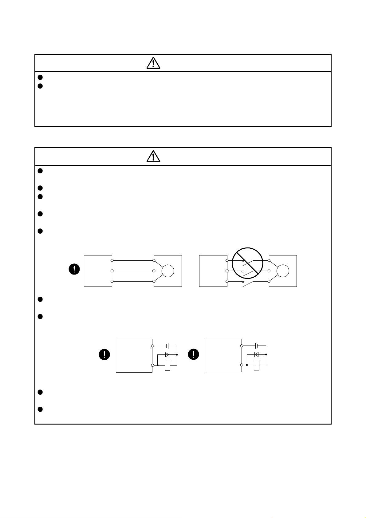
Connect the servo amplifier power output (U, V, and W) to the servo motor power input (U, V, and W)
directly. Do not let a magnetic contactor, etc. intervene. Otherwise, it may cause a malfunction.
Servo amplifier
U
V
W
Servo motor
U
V
W
Servo motorServo amplifier
U
M
V
W
U
V
W
M
The connection diagrams in this Instruction Manual are shown for sink interfaces, unless stated
otherwise.
The surge absorbing diode installed to the DC relay for control output should be fitted in the specified
direction. Otherwise, the emergency stop and other protective circuits may not operate.
Servo amplifier
DOCOM
Control output
signal
For sink output interface
24 V DC
RA
Servo amplifie
DOCOM
Control output
signal
For source output interface
24 V DC
RA
When the cable is not tightened enough to the terminal block, the cable or terminal block may generate
heat because of the poor contact. Be sure to tighten the cable with specified torque.
Connecting a servo motor of the wrong axis to U, V, W, or CN2 of the servo amplifier may cause a
malfunction.
A - 4
Page 6
(3) Test run and adjustment
CAUTION
Before operation, check the parameter settings. Improper settings may cause some machines to operate
unexpectedly.
Never adjust or change the parameter values drastically as doing so will make the operation unstable.
Do not get close to moving parts during the servo-on status.
(4) Usage
CAUTION
When it is assumed that a hazardous condition may occur due to a power failure or product malfunction,
use a servo motor with an external brake to prevent the condition.
Do not disassemble, repair, or modify the equipment.
Before resetting an alarm, make sure that the run signal of the servo amplifier is off in order to prevent a
sudden restart. Otherwise, it may cause an accident.
Use a noise filter, etc. to minimize the influence of electromagnetic interference. Electromagnetic
interference may be given to the electronic equipment used near the servo amplifier.
Burning or breaking a servo amplifier may cause a toxic gas. Do not burn or break it.
Use the servo amplifier with the specified servo motor.
The electromagnetic brake on the servo motor is designed to hold the motor shaft and should not be
used for ordinary braking.
For such reasons as service life and mechanical structure (e.g. where a ball screw and the servo motor
are coupled via a timing belt), the electromagnetic brake may not hold the motor shaft. To ensure safety,
install a stopper on the machine side.
(5) Corrective actions
CAUTION
When it is assumed that a hazardous condition may occur due to a power failure or product malfunction,
use a servo motor with an electromagnetic brake or external brake to prevent the condition.
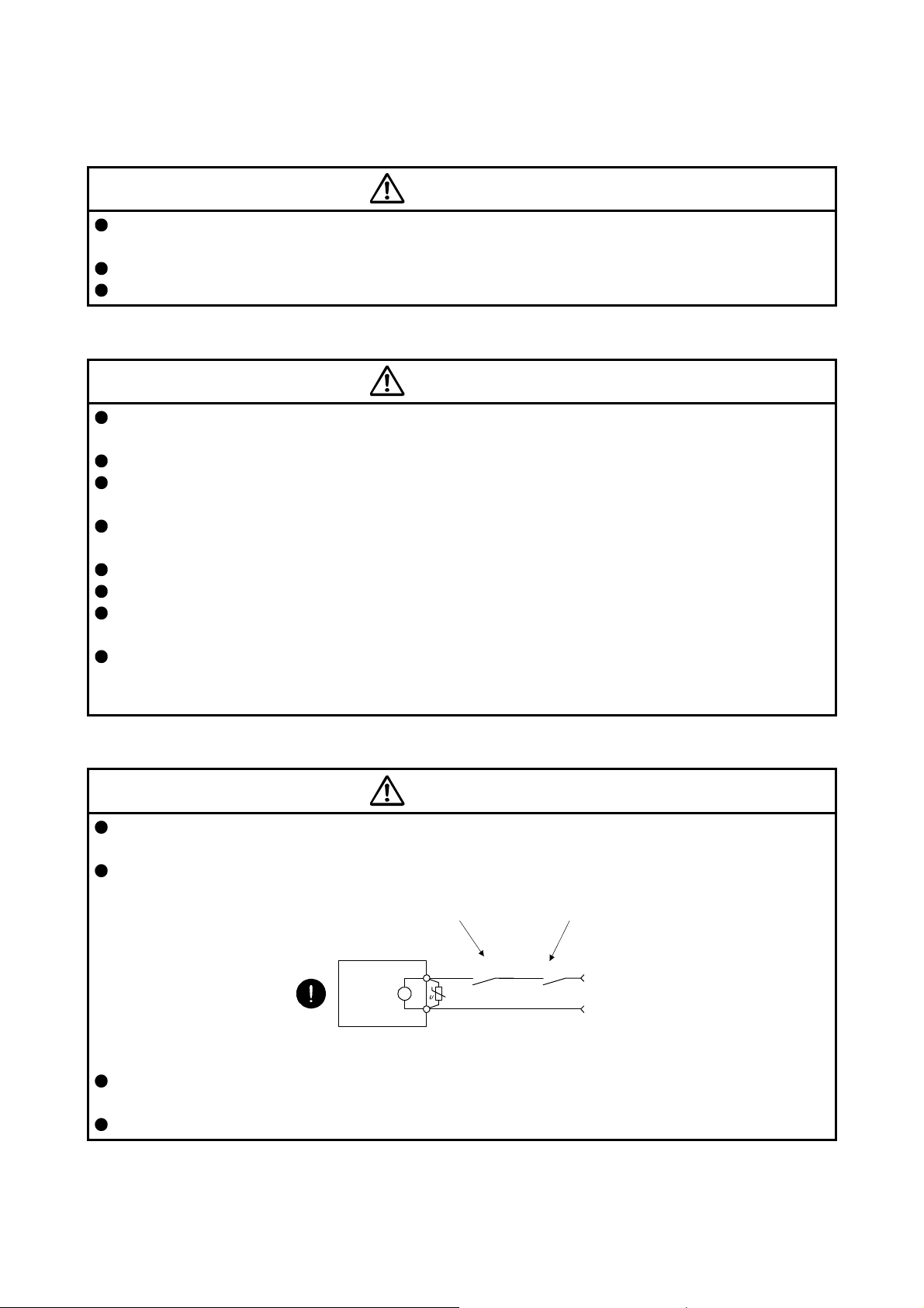
Configure an electromagnetic brake circuit so that it is activated also by an external EMG stop switch.
Contacts must be opened when ALM
(Malfunction) or MBR (Electromagnetic
brake interlock) turns off.
Servo motor
B
Electromagnetic brake
When any alarm has occurred, eliminate its cause, ensure safety, and deactivate the alarm before
restarting operation.
Provide an adequate protection to prevent unexpected restart after an instantaneous power failure.
Contacts must be opened
with the EMG stop switch.
RA
24 V DC
A - 5
Page 7
(6) Maintenance, inspection and parts replacement
CAUTION
With age, the electrolytic capacitor of the servo amplifier will deteriorate. To prevent a secondary
accident due to a malfunction, it is recommended that the electrolytic capacitor be replaced every 10
years when it is used in general environment. For replacement, please contact your local sales office.
When using a servo amplifier whose power has not been turned on for a long time, contact your local
sales office.
(7) General instruction
To illustrate details, the equipment in the diagrams of this Instruction Manual may have been drawn
without covers and safety guards. When the equipment is operated, the covers and safety guards must
be installed as specified. Operation must be performed in accordance with this Instruction Manual.
DISPOSAL OF WASTE
Please dispose a servo amplifier, battery (primary battery) and other options according to your local laws and
regulations.
EEP-ROM life
The number of write times to the EEP-ROM, which stores parameter settings, etc., is limited to 100,000. If
the total number of the following operations exceeds 100,000, the servo amplifier may malfunction when the
EEP-ROM reaches the end of its useful life.
Write to the EEP-ROM due to parameter setting changes
Write to the EEP-ROM due to device changes
Compliance with global standards
Refer to appendix 4 for the compliance with global standards.
«About the manual»
You must have this Instruction Manual and the following manuals to use this servo. Ensure to prepare
them to use the servo safely.
Relevant manuals
Manual name Manual No.
MELSERVO-JE Servo Amplifier Instruction Manual (Troubleshooting) SH(NA)030166
MELSERVO HG-KN_/HG-SN_ Servo Motor Instruction Manual SH(NA)030135
EMC Installation Guidelines IB(NA)67310
A - 6
Page 8

«Cables used for wiring»
Wires mentioned in this Instruction Manual are selected based on the ambient temperature of 40 ˚C.
«U.S. customary units»
U.S. customary units are not shown in this manual. Convert the values if necessary according to the
following table.
Quantity SI (metric) unit U.S. customary unit
Mass 1 [kg] 2.2046 [lb]
Length 1 [mm] 0.03937 [in]
Torque 1 [N•m] 141.6 [oz•in]
Moment of inertia 1 [(× 10-4 kg•m2)] 5.4675 [oz•in2]
Load (thrust load/axial load) 1 [N] 0.2248 [lbf]
Temperature N [°C] × 9/5 + 32 N [°F]
A - 7
Page 9

MEMO
A - 8
Page 10

CONTENTS
1. FUNCTIONS AND CONFIGURATION 1- 1 to 1-12
1.1 Summary ........................................................................................................................................... 1- 1
1.2 Function block diagram ..................................................................................................................... 1- 2
1.3 Servo amplifier standard specifications ............................................................................................ 1- 4
1.4 Combinations of servo amplifiers, servo motors, and controllers ..................................................... 1- 5
1.4.1 Combinations of servo amplifiers and servo motors .................................................................. 1- 5
1.4.2 Compatible controller ................................................................................................................. 1- 5
1.5 Function list ....................................................................................................................................... 1- 6
1.6 Model designation ............................................................................................................................. 1- 8
1.7 Structure ........................................................................................................................................... 1- 9
1.7.1 Parts identification ...................................................................................................................... 1- 9
1.8 Configuration including peripheral equipment ................................................................................. 1-11
2. INSTALLATION 2- 1 to 2- 8
2.1 Installation direction and clearances ................................................................................................ 2- 2
2.2 Keep out foreign materials ................................................................................................................ 2- 3
2.3 Encoder cable stress ........................................................................................................................ 2- 4
2.4 SSCNET III cable laying ................................................................................................................... 2- 4
2.5 Inspection items ................................................................................................................................ 2- 6
2.6 Parts having service lives ................................................................................................................. 2- 7
3. SIGNALS AND WIRING 3- 1 to 3-42
3.1 Input power supply circuit ................................................................................................................. 3- 2
3.2 I/O signal connection example ......................................................................................................... 3-11
3.2.1 For sink I/O interface ................................................................................................................. 3-11
3.2.2 For source I/O interface ............................................................................................................ 3-12
3.3 Explanation of power supply system ............................................................................................... 3-13
3.3.1 Signal explanations ................................................................................................................... 3-13
3.3.2 Power-on sequence .................................................................................................................. 3-14
3.3.3 Wiring CNP1 and CNP2 ............................................................................................................ 3-15
3.4 Connectors and pin assignment ...................................................................................................... 3-17
3.5 Signal (device) explanations ............................................................................................................ 3-18
3.5.1 Input device ............................................................................................................................... 3-18
3.5.2 Output device ............................................................................................................................ 3-19
3.5.3 Power supply ............................................................................................................................. 3-20
3.6 Forced stop deceleration function ................................................................................................... 3-21
3.6.1 Forced stop deceleration function ............................................................................................. 3-21
3.6.2 Base circuit shut-off delay time function ................................................................................... 3-22
3.6.3 Vertical axis freefall prevention function ................................................................................... 3-23
3.6.4 Residual risks of the forced stop function (EM2) ...................................................................... 3-23
3.7 Alarm occurrence timing chart ......................................................................................................... 3-24
3.7.1 When you use the forced stop deceleration function ................................................................ 3-24
3.7.2 When you do not use the forced stop deceleration function ..................................................... 3-25
3.7.3 Hot line forced stop function...................................................................................................... 3-26
3.8 Interfaces ......................................................................................................................................... 3-32
1
Page 11

3.8.1 Internal connection diagram ...................................................................................................... 3-32
3.8.2 Detailed explanation of interfaces ............................................................................................. 3-33
3.8.3 Source I/O interfaces ................................................................................................................ 3-34
3.9 SSCNET III cable connection .......................................................................................................... 3-35
3.10 Servo motor with an electromagnetic brake .................................................................................. 3-37
3.10.1 Safety precautions .................................................................................................................. 3-37
3.10.2 Timing chart ............................................................................................................................ 3-38
3.11 Grounding ...................................................................................................................................... 3-41
4. STARTUP 4- 1 to 4-14
4.1 Switching power on for the first time ................................................................................................. 4- 1
4.1.1 Startup procedure ...................................................................................................................... 4- 1
4.1.2 Wiring check ............................................................................................................................... 4- 2
4.1.3 Surrounding environment ........................................................................................................... 4- 3
4.2 Startup .............................................................................................................................................. 4- 4
4.3 Switch setting and display of the servo amplifier .............................................................................. 4- 5
4.3.1 Axis selection rotary switch (SW1) ............................................................................................. 4- 5
4.3.2 Scrolling display ......................................................................................................................... 4- 7
4.3.3 Status display of an axis ............................................................................................................ 4- 8
4.4 Test operation .................................................................................................................................. 4-10
4.5 Test operation mode ........................................................................................................................ 4-10
4.5.1 Test operation mode in MR Configurator2 ................................................................................ 4-11
4.5.2 Motor-less operation in the controller ........................................................................................ 4-13
5. PARAMETERS 5- 1 to 5-38
5.1 Parameter list .................................................................................................................................... 5- 1
5.1.1 Basic setting parameters ([Pr. PA_ _ ]) ...................................................................................... 5- 2
5.1.2 Gain/filter setting parameters ([Pr. PB_ _ ]) ............................................................................... 5- 3
5.1.3 Extension setting parameters ([Pr. PC_ _ ]) .............................................................................. 5- 4
5.1.4 I/O setting parameters ([Pr. PD_ _ ]) ......................................................................................... 5- 6
5.1.5 Extension setting 2 parameters ([Pr. PE_ _ ]) ............................................................................ 5- 7
5.1.6 Extension setting 3 parameters ([Pr. PF_ _ ]) ............................................................................ 5- 8
5.2 Detailed list of parameters ............................................................................................................... 5-10
5.2.1 Basic setting parameters ([Pr. PA_ _ ]) ..................................................................................... 5-10
5.2.2 Gain/filter setting parameters ([Pr. PB_ _ ]) .............................................................................. 5-18
5.2.3 Extension setting parameters ([Pr. PC_ _ ]) ............................................................................. 5-30
5.2.4 I/O setting parameters ([Pr. PD_ _ ]) ........................................................................................ 5-33
5.2.5 Extension setting 2 parameters ([Pr. PE_ _ ]) ........................................................................... 5-36
5.2.6 Extension setting 3 parameters ([Pr. PF_ _ ]) ........................................................................... 5-37
6. NORMAL GAIN ADJUSTMENT 6- 1 to 6-18
6.1 Different adjustment methods ........................................................................................................... 6- 1
6.1.1 Adjustment on a single servo amplifier ...................................................................................... 6- 1
6.1.2 Adjustment using MR Configurator2 .......................................................................................... 6- 2
6.2 One-touch tuning .............................................................................................................................. 6- 3
6.2.1 One-touch tuning flowchart ........................................................................................................ 6- 4
6.2.2 Display transition and operation procedure of one-touch tuning ............................................... 6- 5
6.2.3 Caution for one-touch tuning ...................................................................................................... 6- 8
2
Page 12

6.3 Auto tuning ........................................................................................................................................ 6- 9
6.3.1 Auto tuning mode ....................................................................................................................... 6- 9
6.3.2 Auto tuning mode basis ............................................................................................................. 6-10
6.3.3 Adjustment procedure by auto tuning ....................................................................................... 6-11
6.3.4 Response level setting in auto tuning mode ............................................................................. 6-12
6.4 Manual mode ................................................................................................................................... 6-13
6.5 2 gain adjustment mode .................................................................................................................. 6-16
7. SPECIAL ADJUSTMENT FUNCTIONS 7- 1 to 7-30
7.1 Filter setting ...................................................................................................................................... 7- 1
7.1.1 Machine resonance suppression filter ....................................................................................... 7- 1
7.1.2 Adaptive filter II ........................................................................................................................... 7- 4
7.1.3 Shaft resonance suppression filter ............................................................................................. 7- 6
7.1.4 Low-pass filter ............................................................................................................................ 7- 7
7.1.5 Advanced vibration suppression control II ................................................................................. 7- 7
7.1.6 Command notch filter ................................................................................................................ 7-11
7.2 Gain switching function .................................................................................................................... 7-13
7.2.1 Applications ............................................................................................................................... 7-13
7.2.2 Function block diagram ............................................................................................................. 7-14
7.2.3 Parameter .................................................................................................................................. 7-15
7.2.4 Gain switching procedure ......................................................................................................... 7-18
7.3 Tough drive function ........................................................................................................................ 7-22
7.3.1 Vibration tough drive function.................................................................................................... 7-22
7.3.2 Instantaneous power failure tough drive function ..................................................................... 7-24
7.4 Model adaptive control disabled ...................................................................................................... 7-26
7.5 Lost motion compensation function ................................................................................................. 7-27
8. TROUBLESHOOTING 8- 1 to 8- 6
8.1 Explanation for the lists ..................................................................................................................... 8- 1
8.2 Alarm list ........................................................................................................................................... 8- 2
8.3 Warning list ....................................................................................................................................... 8- 5
9. DIMENSIONS 9- 1 to 9- 4
9.1 Servo amplifier .................................................................................................................................. 9- 1
9.2 Connector ......................................................................................................................................... 9- 4
10. CHARACTERISTICS 10- 1 to 10- 8
10.1 Overload protection characteristics .............................................................................................. 10- 1
10.2 Power supply capacity and generated loss .................................................................................. 10- 3
10.3 Dynamic brake characteristics ...................................................................................................... 10- 5
10.3.1 Dynamic brake operation ....................................................................................................... 10- 5
10.3.2 Permissible load to motor inertia when the dynamic brake is used ....................................... 10- 6
10.4 Cable bending life ......................................................................................................................... 10- 7
10.5 Inrush current at power-on ........................................................................................................... 10- 7
3
Page 13

11. OPTIONS AND PERIPHERAL EQUIPMENT 11- 1 to 11-48
11.1 Cable/connector sets .................................................................................................................... 11- 1
11.1.1 Combinations of cable/connector sets ................................................................................... 11- 2
11.1.2 SSCNET III cable ................................................................................................................... 11- 5
11.1.3 Battery cable and junction battery cable ................................................................................ 11- 7
11.2 Regenerative option ...................................................................................................................... 11- 8
11.2.1 Combination and regenerative power .................................................................................... 11- 8
11.2.2 Selection of regenerative option ............................................................................................ 11- 9
11.2.3 Parameter setting .................................................................................................................. 11-10
11.2.4 Connection of regenerative option ........................................................................................ 11-11
11.2.5 Dimensions ........................................................................................................................... 11-15
11.3 Junction terminal block PS7DW-20V14B-F (recommended) ...................................................... 11-17
11.4 MR Configurator2 ........................................................................................................................ 11-18
11.4.1 Specifications ........................................................................................................................ 11-18
11.4.2 System requirements ............................................................................................................ 11-19
11.4.3 Precautions for using USB communication function ............................................................. 11-20
11.5 Battery .......................................................................................................................................... 11-21
11.5.1 Selection of battery ............................................................................................................... 11-21
11.5.2 MR-BAT6V1SET-A battery ................................................................................................... 11-22
11.5.3 MR-BT6VCASE battery case ................................................................................................ 11-26
11.5.4 MR-BAT6V1 battery .............................................................................................................. 11-32
11.6 Selection example of wires .......................................................................................................... 11-33
11.7 Molded-case circuit breakers, fuses, magnetic contactors ......................................................... 11-34
11.8 Power factor improving AC reactor .............................................................................................. 11-35
11.9 Relay (recommended) ................................................................................................................. 11-36
11.10 Noise reduction techniques ....................................................................................................... 11-37
11.11 Earth-leakage current breaker ................................................................................................... 11-43
11.12 EMC filter (recommended) ........................................................................................................ 11-45
12. ABSOLUTE POSITION DETECTION SYSTEM 12- 1 to 12- 4
12.1 Summary ....................................................................................................................................... 12- 1
12.1.1 Features ................................................................................................................................. 12- 1
12.1.2 Configuration .......................................................................................................................... 12- 2
12.1.3 Parameter setting ................................................................................................................... 12- 2
12.1.4 Confirmation of absolute position detection data ................................................................... 12- 2
12.2 Battery ........................................................................................................................................... 12- 3
12.2.1 Using the MR-BAT6V1SET-A battery .................................................................................... 12- 3
12.2.2 Using the MR-BT6VCASE battery case................................................................................. 12- 4
APPENDIX App. - 1 to App. -18
App. 1 Peripheral equipment manufacturer (for reference) .............................................................. App.- 1
App. 2 Handling of AC servo amplifier batteries for the United Nations Recommendations on the
Transport of Dangerous Goods ............................................................................................ App.- 1
App. 3 Symbol for the new EU Battery Directive .............................................................................. App.- 3
App. 4 Compliance with global standards ........................................................................................ App.- 3
App. 5 SSCNET III cable (SC-J3BUS_M-C) manufactured by Mitsubishi Electric System &
Service ................................................................................................................................. App.-15
App. 6 Low-voltage directive ........................................................................................................... App.-16
4
Page 14

App. 7 When turning on or off the input power supply with DC power supply ................................ App.-17
App. 8 When using the hot line forced stop function in combination with MR-J4-_B servo
amplifier ................................................................................................................................ App.-18
5
Page 15

MEMO
6
Page 16

1. FUNCTIONS AND CONFIGURATION
1. FUNCTIONS AND CONFIGURATION
1.1 Summary
POINT
Refer to section 1.4.2 for compatible controllers.
The Mitsubishi general-purpose AC servo MELSERVO-JE series have limited functions with keeping high
performance based on MELSERVO-J4 series.
The MR-JE-_B servo amplifier is connected to controllers, including a servo system controller, on the highspeed synchronous network SSCNET III/H. The servo amplifier directly receives a command from a
controller to drive a servo motor.
SSCNET III/H achieves high-speed communication of 150 Mbps full duplex with high noise immunity due to
the SSCNET III optical cables. Large amounts of data can be exchanged in real-time between the controller
and the servo amplifier. Servo monitor information can be stored in the upper information system and used
for control.
With one-touch tuning and real-time auto tuning, you can easily and automatically adjust the servo gains
according to the machine.
The tough drive function, drive recorder function, and preventive maintenance support function strongly
support machine maintenance.
The servo amplifier has a USB communication interface. Therefore, you can connect the servo amplifier to
the personal computer with MR Configurator2 installed to perform the parameter setting, test operation, gain
adjustment, and others.
The servo motor equipped with an absolute position encoder whose resolution is 131072 pulses/rev will
enable a high-accuracy positioning.
1 - 1
Page 17
1. FUNCTIONS AND CONFIGURATION
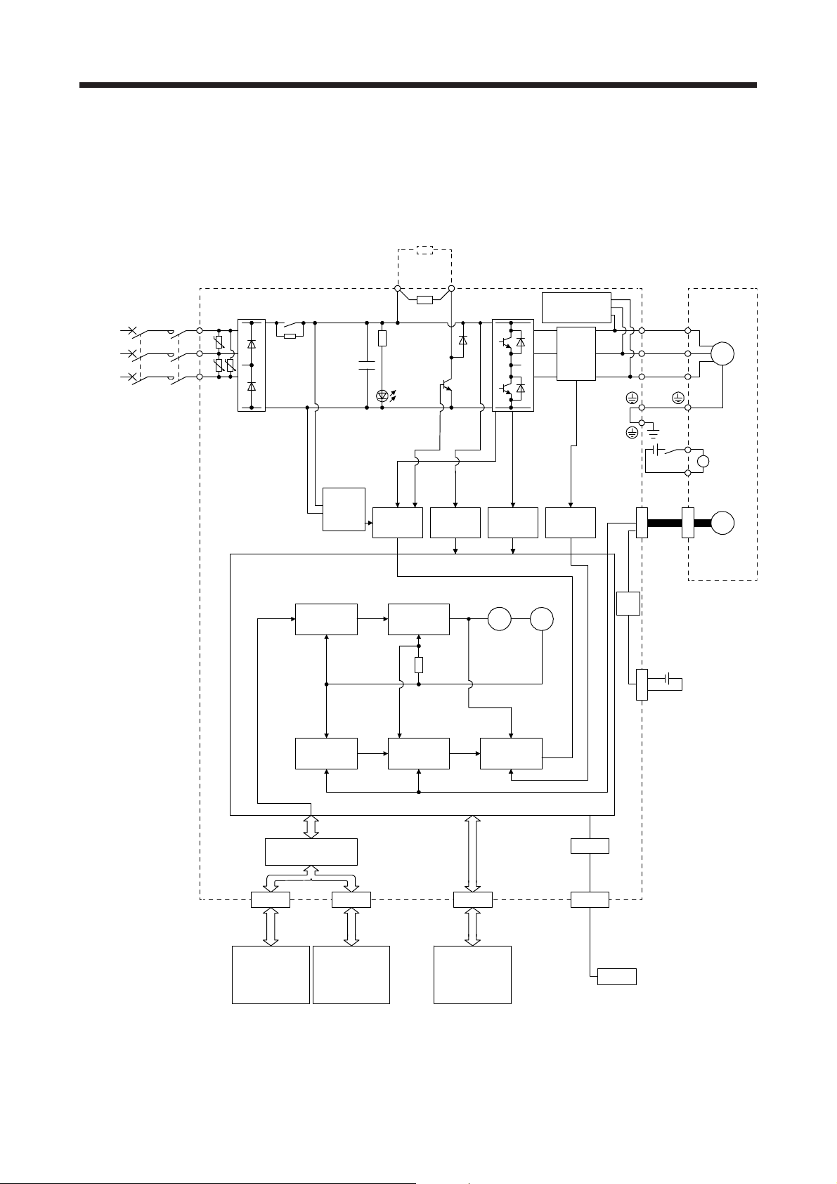
1.2 Function block diagram
The function block diagram of this servo is shown below.
(1) MR-JE-100B or less
Regenerative
option
(Note 2)
Power
supply
U
V
W
RA
Servo motor
M
B1
Electromagnetic
B
brake
B2
Encoder
P+
Diode
stack
MCMCCB
L1
U
L2
U U
L3
Relay
Position
command
input
Control
circuit
power
Model
position
control
+
CHARGE
lamp
Base
amplifier
(Note 1)
Regenerative
TR
Model
speed
control
C
Voltage
detection
Overcurrent
protection
Virtual
motor
brake circuit
detection
Virtual
encoder
Dynamic
Current
detector
Current
Stepdown
circuit
U
V
W
24 V DC
CN2
Model position
Actual
position
control
I/F Control
CN1A CN1B CN3
Servo system
controller or
servo amplifier
Servo
amplifier
or cap
Model speed Model torque
Actual
speed
control
Digital I/O
control
Current
control
Note 1. The built-in regenerative resistor is not provided for MR-JE-10B and MR-JE-20B.
2. For 1-phase 200 V AC to 240 V AC, connect the power supply to L1 and L3. Leave L2 open.
For the power supply specifications, refer to section 1.3.
USB
CN5
Personal
computer
USB
CN4
Battery
(for absolute position
detection system)
1 - 2
Page 18
1. FUNCTIONS AND CONFIGURATION
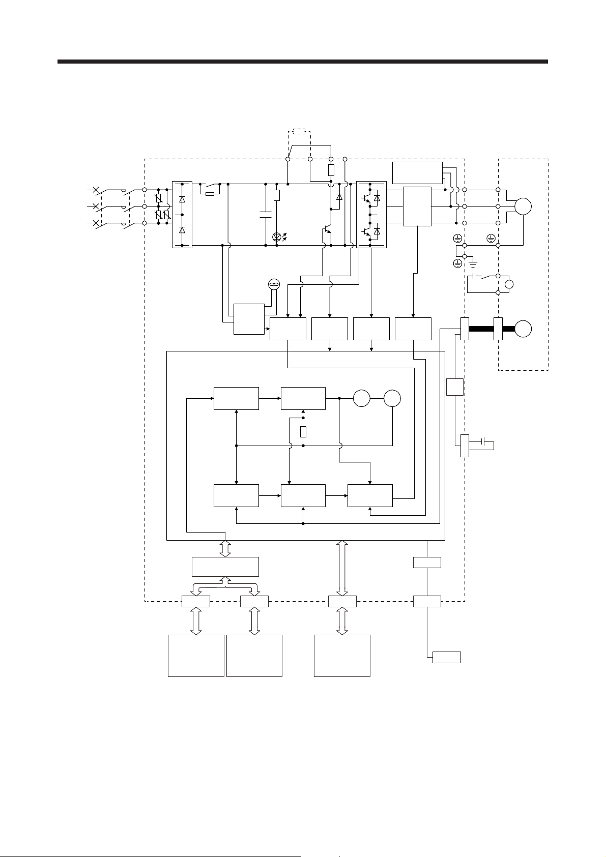
(2) MR-JE-200B or more
Regenerative
option
(Note 1)
Power
supply
U
V
W
RA
Servo motor
M
B1
Electromagnetic
B
brake
B2
N- (Note 2)CDP+
Diode
stack
MCMCCB
L1
U
L2
UU
L3
Relay
+
CHARGE
lamp
Regenerative
TR
Dynamic
brake circuit
Current
detector
U
V
W
Cooling fan
24 V DC
Control
circuit
power
Base
amplifier
Voltage
detection
Overcurrent
protection
Current
detection
CN2
Encoder
motor
Virtual
encoder
Stepdown
circuit
Position
command
input
Model
position
control
Model
speed
control
Virtual
USB
USB
CN4
Battery
(for absolute position
detection system)
Model position
Actual
position
control
Model speed Model torque
Actual
speed
control
I/F Control
CN1A CN1B CN3
controller or
servo amplifier
Servo
amplifier
or cap
Digital I/O
control
Current
control
USB
CN5
Personal
computerServo system
Note 1. A 1-phase 200 V AC to 240 V AC power supply may be used with the servo amplifier of MR-JE-200B. For 1-phase 200 V AC
to 240 V AC, connect the power supply to L1 and L2. Leave L3 open. For the power supply specifications, refer to section 1.3.
2. This terminal is for manufacturer adjustment. Leave this terminal open.
1 - 3
Page 19
1. FUNCTIONS AND CONFIGURATION
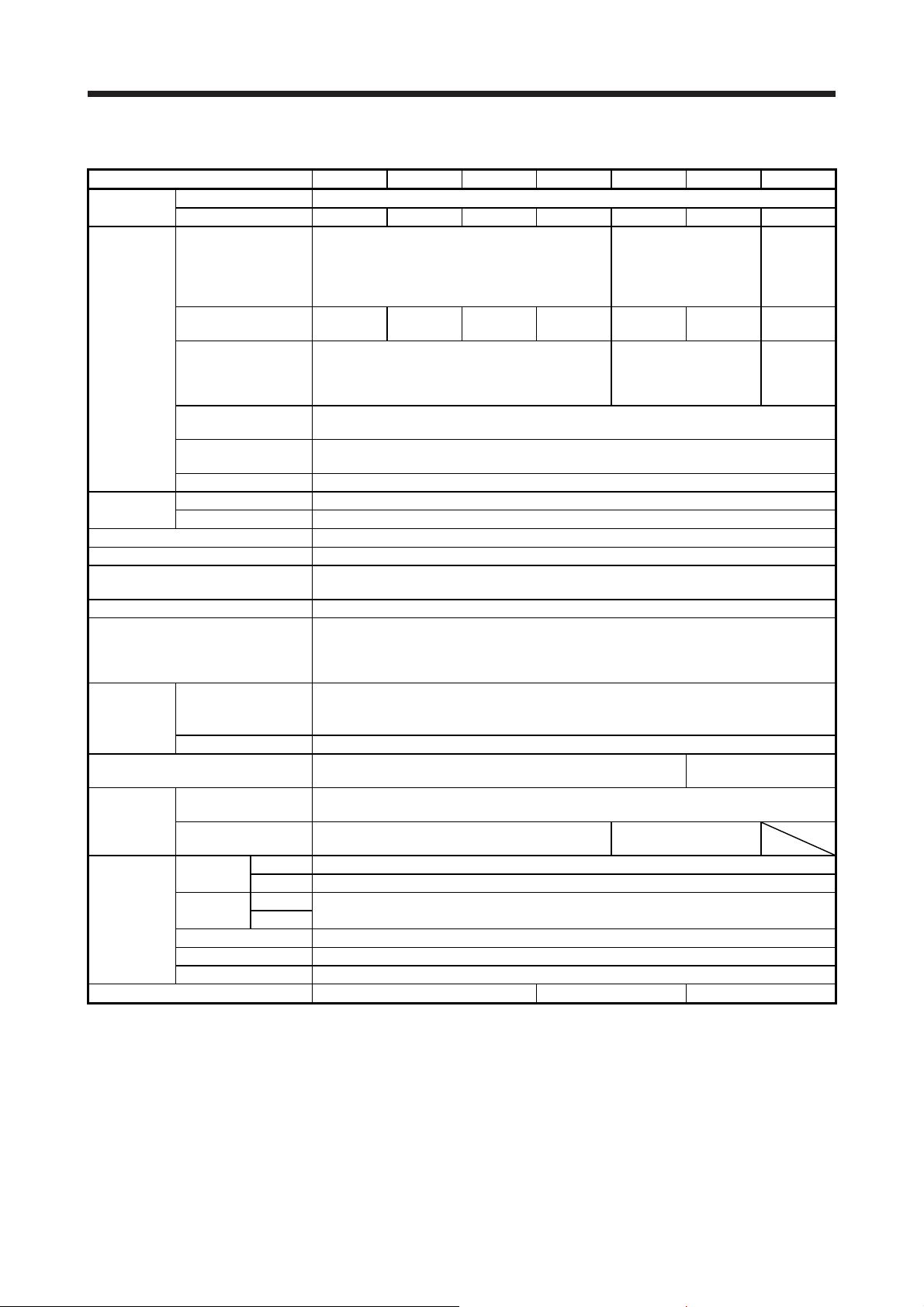
1.3 Servo amplifier standard specifications
Model: MR-JE- 10B 20B 40B 70B 100B 200B 300B
Output
Power supply
input
Interface
power supply
Control method Sine-wave PWM control, current control method
Dynamic brake Built-in
SSCNET III/H communication cycle
(Note 3)
Communication function USB: Connection to a personal computer or others (MR Configurator2-compatible)
Protective functions
Compliance
to standards
Structure (IP rating) Natural cooling, open (IP20)
Close
mounting
(Note 4)
Storage -20 ˚C to 65 ˚C (non-freezing)
Environment Storage
Ambience Indoors (no direct sunlight); no corrosive gas, inflammable gas, oil mist or dust
Altitude 1000 m or less above sea level
Vibration resistance 5.9 m/s2, at 10 Hz to 55 Hz (directions of X, Y and Z axes)
Mass [kg] 0.8 1.5 2.1
Note 1. This value is applicable when a 3-phase power supply is used.
2. The current capacity 0.1 A is applicable when all I/O signals are used. The current capacity can be decreased by reducing the
3. The communication cycle depends on the controller specifications and the number of axes connected.
4. When closely mounting the servo amplifier, operate them at the ambient temperatures of 0 ˚C to 45 ˚C or at 75% or smaller
5. When using 1-phase 200 V AC to 240 V AC power supply, operate the servo amplifier at 75% or smaller effective load ratio.
Rated voltage 3-phase 170 V AC
Rated current [A] 1.1 1.5 2.8 5.8 6.0 11.0 11.0
Voltage/frequency
Rated current
(Note 1)
Permissible voltage
fluctuation
Permissible frequency
fluctuation
Power supply
capacity
Inrush current [A] Refer to section 10.5.
Voltage 24 V DC ± 10%
Current capacity [A] (Note 2) 0.1
CE marking
UL standard UL 508C
3-phase power supply
input
1-phase power supply
input
Ambient
temperature
Ambient
humidity
number of I/O points.
effective load ratio.
[kVA] Refer to section 10.2.
Operation 0 ˚C to 55 ˚C (non-freezing)
Operation
3-phase or 1-phase 200 V AC to 240 V AC, 50
Hz/60 Hz
[A] 0.9 1.5 2.6 3.8 5.0 10.5 14.0
3-phase or 1-phase 170 V AC to 264 V AC
Within ±5%
0.444 ms, 0.888 ms
Overcurrent shut-off, regenerative overvoltage shut-off, overload shut-off (electronic thermal),
servo motor overheat protection, encoder error protection, regenerative error protection,
undervoltage protection, instantaneous power failure protection, overspeed protection, and
error excessive protection
LVD: EN 61800-5-1
EMC: EN 61800-3
MD: EN ISO 13849-1, EN 61800-5-2, EN 62061
Possible
Possible Impossible
90%RH or lower (non-condensing)
3-phase or 1-phase 200
V AC to 240 V AC, 50
Hz/60 Hz (Note 5)
3-phase or 1-phase 170
V AC to 264 V AC
(Note 5)
Force cooling, open
200 V AC
Hz/60 Hz
170 V AC
(IP20)
3-phase
to 240 V
AC, 50
3-phase
to 264 V
AC
1 - 4
Page 20
1. FUNCTIONS AND CONFIGURATION
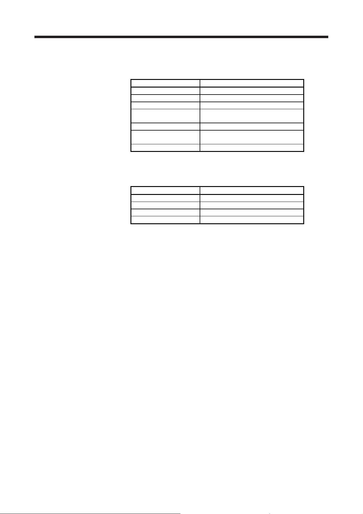
1.4 Combinations of servo amplifiers, servo motors, and controllers
1.4.1 Combinations of servo amplifiers and servo motors
Servo amplifier Servo motor
MR-JE-10B HG-KN13_
MR-JE-20B HG-KN23_
MR-JE-40B HG-KN43_
MR-JE-70B HG-KN73_
HG-SN52_
MR-JE-100B HG-SN102_
MR-JE-200B HG-SN152_
HG-SN202_
MR-JE-300B HG-SN302_
1.4.2 Compatible controller
For the simple motion module, refer to the user's manual of each series.
MELSEC iQ-R series RD77MS_
MELSEC-Q series QD77MS_
MELSEC-L series LD77MS_
MELSEC iQ-F series FX5-40SSC-S
Series Simple motion module
1 - 5
Page 21

1. FUNCTIONS AND CONFIGURATION
1.5 Function list
The following table lists the functions of this servo. For details of the functions, refer to each section
indicated in the detailed explanation field.
Function Description
This function realizes a high response and stable control following the ideal model.
Model adaptive control
Position control mode This servo amplifier is used as a position control servo.
Speed control mode This servo amplifier is used as a speed control servo.
Torque control mode This servo amplifier is used as a torque control servo.
High-resolution encoder
Absolute position detection
system
Gain switching function
Advanced vibration
suppression control II
Machine resonance
suppression filter
Shaft resonance suppression
filter
Adaptive filter II
Low-pass filter
Machine analyzer function
Robust filter
Slight vibration suppression
control
Auto tuning
Regenerative option
Alarm history clear This function clears the alarm history. [Pr. PC21]
Output signal selection
(device settings)
Output signal (DO) forced
output
Test operation mode
MR Configurator2
One-touch tuning
Tough drive function
The two-degrees-of-freedom model adaptive control enables you to set a response to
the command and response to the disturbance separately.
Additionally, this function can be disabled. Refer to section 7.4 to disable this function.
A high-resolution encoder of 131072 pulses/rev is used as the encoder of the rotary
servo motor compatible with the MELSERVO-JE series.
Setting a home position once makes home position return unnecessary at every
power-on.
You can switch gains during rotation and during stop, and can use input devices to
switch gains during operation.
This function suppresses vibration at the arm end or residual vibration. Section 7.1.5
This filter function (notch filter) decreases the gain of the specific frequency to
suppress the resonance of the mechanical system.
When a load is mounted to the servo motor shaft, resonance by shaft torsion during
driving may generate a mechanical vibration at high frequency. The shaft resonance
suppression filter suppresses the vibration.
The servo amplifier detects mechanical resonance and sets filter characteristics
automatically to suppress mechanical vibration.
This function suppresses high-frequency resonance which occurs as servo system
response is increased.
This function analyzes the frequency characteristic of the mechanical system by
simply connecting an MR Configurator2 installed personal computer and servo
amplifier.
MR Configurator2 is necessary for this function.
This function enhances the disturbance response when the response level remains
low because the load to motor inertia ratio of axes, such as a roll feed axis, is high.
This function suppresses vibration of ±1 pulse generated at a servo motor stop. [Pr. PB24]
This function automatically adjusts the gain to an optimum value if load applied to the
servo motor shaft varies.
Used when the built-in regenerative resistor of the servo amplifier does not have
sufficient regenerative capability for the regenerative power generated.
The output devices including MBR (Electromagnetic brake interlock) and ALM
(Malfunction) can be assigned to certain pins of the CN3 connector.
Output signal can be forced on/off independently of the servo status.
Use this function for checking output signal wiring, etc.
Jog operation, positioning operation, motor-less operation, DO forced output, and
program operation
MR Configurator2 is necessary for this function.
Using a personal computer, you can perform the parameter setting, test operation,
monitoring, and others.
Gain adjustment is performed just by one click on a certain button on MR
Configurator2.
MR Configurator2 is necessary for this function.
This function makes the equipment continue operating even under the condition that
an alarm occurs.
The tough drive function includes two types: the vibration tough drive and the
instantaneous power failure tough drive.
Detailed
explanation
Chapter 12
Section 7.2
Section 7.1.1
Section 7.1.3
Section 7.1.2
Section 7.1.4
[Pr. PE41]
Section 6.3
Section 11.2
[Pr. PD07]
Section 4.5.1
(1) (d)
Section 4.5
Section 11.4
Section 6.2
Section 7.3
1 - 6
Page 22

1. FUNCTIONS AND CONFIGURATION
Function Description
This function continuously monitors the servo status and records the status transition
before and after an alarm for a fixed period of time. You can check the recorded data
on the drive recorder window on MR Configurator2 by clicking the "Graph" button.
However, the drive recorder will not operate on the following conditions.
Drive recorder function
Servo amplifier life diagnosis
function
Power monitoring function
Machine diagnosis function
Continuous operation to
torque control mode
Lost motion compensation
function
Hot line forced stop function
1. You are using the graph function of MR Configurator2.
2. You are using the machine analyzer function.
3. [Pr. PF21] is set to "-1".
4. The controller is not connected (except the test operation mode).
5. An alarm related to the controller is occurring.
You can check the cumulative energization time and the number of on/off times of the
inrush relay. This function gives an indication of the replacement time for parts of the
servo amplifier including a capacitor and a relay before they malfunction.
MR Configurator2 is necessary for this function.
This function calculates the power running energy and the regenerative power from
the data in the servo amplifier such as speed and current. Power consumption and
others are displayed on MR Configurator2. Since the servo amplifier sends data to a
servo system controller, you can analyze the data and display the data on a display
with the SSCNET III/H system.
From the data in the servo amplifier, this function estimates the friction and vibrational
component of the drive system in the equipment and recognizes an error in the
machine parts, including a ball screw and bearing.
MR Configurator2 is necessary for this function.
This function allows smooth switching of the mode from the position control mode or
speed control mode to the torque control mode without stopping. This function
eliminates rapid change of speed and torque, contributing to reduction in load to the
machine and high-quality product molding. For details of the continuous operation to
torque control mode, refer to the manuals for servo system controllers.
This function corrects response delays caused when the machine travel direction is
reversed.
This function enables all the normally operating MR-JE-_B servo amplifiers to
decelerate to a stop by transmitting hot line forced stop signals via the controller if an
alarm occurs in the MR-JE-_B servo amplifier.
Detailed
explanation
[Pr. PA23]
[Pr. PB03]
Manuals of
servo system
controllers
Section 7.5
Section 3.7.3
1 - 7
Page 23
1. FUNCTIONS AND CONFIGURATION
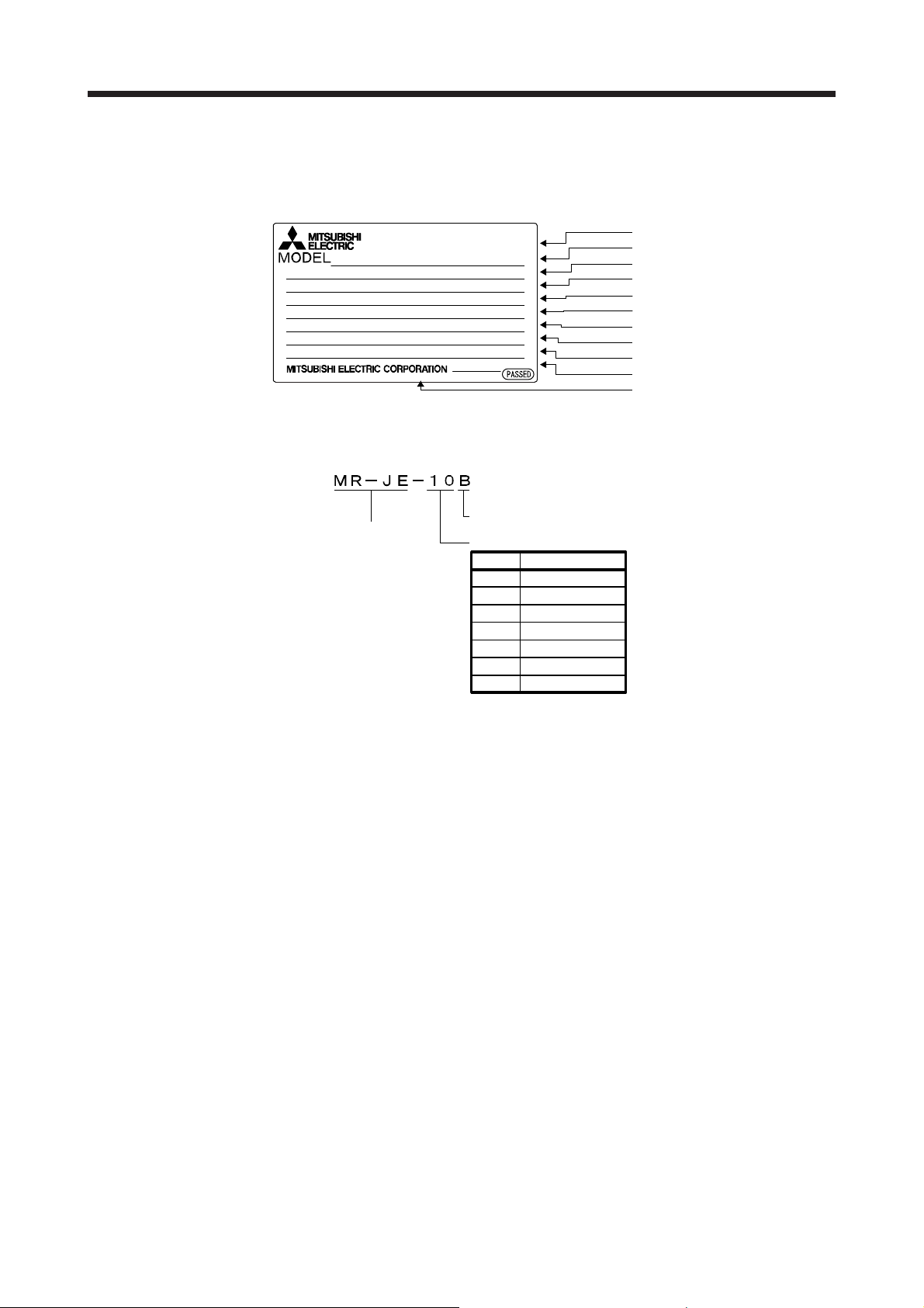
1.6 Model designation
(1) Rating plate
The following shows an example of the rating plate for explanation of each item.
AC SERVO
SER. A4Y001001
MR-JE-10B
POWER
: 100W
INPUT
: 3AC/200-240V 0.9A/1.5A 50/60Hz
OUTPUT
: 3PH170V 0-360Hz 1.1A
STD.: IEC/EN61800-5-1 MAN.: IB(NA)0300194
Max. Surrounding Air Temp.: 55°C
IP20
MSIP-REI-MEK- TC300A982G51
TOKYO 100-8310, JAPAN MADE IN JAPAN
DATE: 2014-11
(2) Model
The following describes what each block of a model name indicates.
SSCNETIII/H interface
Series
Rated output
Symbol Rated output [kW]
10 0.1
20 0.2
40 0.4
70 0.75
100 1
200 2
300 3
Serial number
Model
Capacity
Applicable power supply
Rated output current
Standard, Manual number
Ambient temperature
IP rating
KC certification number
The year and month of manufacture
Country of origin
1 - 8
Page 24
1. FUNCTIONS AND CONFIGURATION
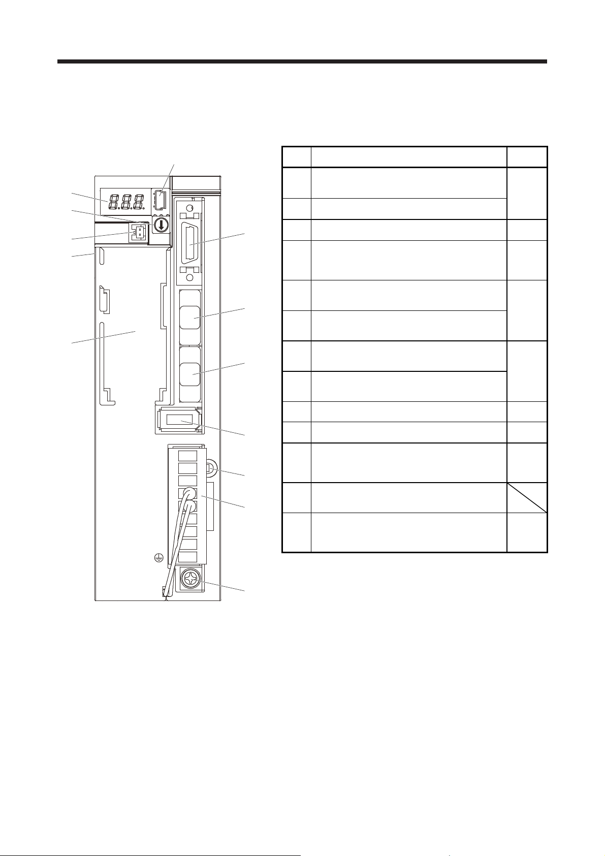
1.7 Structure
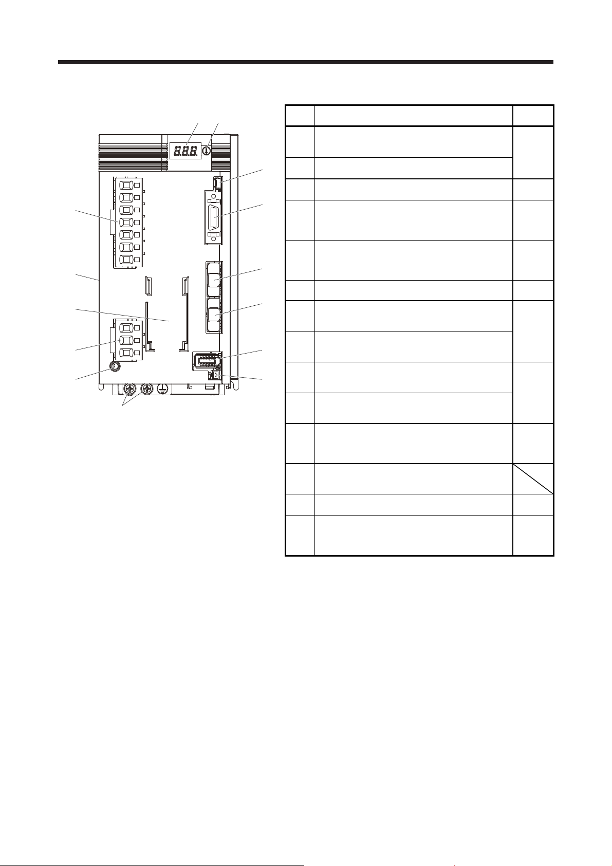
1.7.1 Parts identification
(1) MR-JE-100B or less
No. Name/Application
(1)
(2)
(3)
(4)
(5)
(6)
(7)
(8)
(9)
(10)
(11)
(12)
(13)
(1)
(2)
(5)
(9)
(6)
(3)
(4)
Side
(7)
(8)
(10)
(12)
(11)
Detailed
explanation
Display
The 3-digit, 7-segment LED shows the servo status and the
alarm number.
Axis selection rotary switch (SW1)
Used to set the axis number of the servo amplifier.
USB communication connector (CN5)
Used to connect this connector to a personal computer.
I/O signal connector (CN3)
Used to connect digital I/O signals.
Battery connector (CN4)
Used to connect the battery for absolute position data
backup.
Battery holder
Used to house the battery for absolute position data
backup.
SSCNET III cable connector (CN1A)
Used to connect the servo system controller or the previous
axis servo amplifier.
SSCNET III cable connector (CN1B)
Used to connect the next axis servo amplifier. For the final
axis, put a cap.
Rating plate Section
Encoder connector (CN2)
Used to connect the servo motor encoder.
Power connector (CNP1)
Used to connect the input power supply, built-in
regenerative resistor, regenerative option, and servo motor.
Charge lamp
When the main circuit is charged, this lamp will light up.
While this lamp is lit, do not reconnect the cables.
Protective earth (PE) terminal
Grounding terminal
Section
4.3
Section
11.4
Section
3.2
Section
3.4
Chapter
12
Section
3.2
Section
3.4
1.6
Section
3.4
Section
3.1
Section
3.3
Section
3.1
Section
3.3
(13)
1 - 9
Page 25
1. FUNCTIONS AND CONFIGURATION
(2) MR-JE-200B or more
No. Name/Application
(1)
(3)
(2)
(3)
(4)
(4)
(9)
(5)
(6)
(10)
(7)
(13)
(8)
(8)
(9)
(10)
(11)
(12)
(13)
(14)
(5)
(6)
(7)
(11)
(12)
Side
(14)
(1)
(2)
Detailed
explanation
Display
The 3-digit, 7-segment LED shows the servo status and the
alarm number.
Axis selection rotary switch (SW1)
Used to set the axis number of the servo amplifier.
USB communication connector (CN5)
Used to connect this connector to a personal computer.
I/O signal connector (CN3)
Used to connect digital I/O signals.
Power connector (CNP1)
Used to connect the input power supply and regenerative
option.
Rating plate Section
Battery holder
Used to house the battery for absolute position data
backup.
Battery connector (CN4)
Used to connect the battery for absolute position data
backup.
SSCNET III cable connector (CN1A)
Used to connect the servo system controller or the previous
axis servo amplifier.
SSCNET III cable connector (CN1B)
Used to connect the next axis servo amplifier. For the final
axis, put a cap.
Servo motor power connector (CNP2)
Used to connect the servo motor.
Charge lamp
When the main circuit is charged, this lamp will light up.
While this lamp is lit, do not reconnect the cables.
Encoder connector (CN2)
Used to connect the servo motor encoder.
Protective earth (PE) terminal
Grounding terminal
Section
4.3
Section
11.4
Section
3.2
Section
3.4
Section
3.1
Section
3.3
1.6
Chapter
12
Section
3.2
Section
3.4
Section
3.1
Section
3.3
Section
3.4
Section
3.1
Section
3.3
1 - 10
Page 26
1. FUNCTIONS AND CONFIGURATION
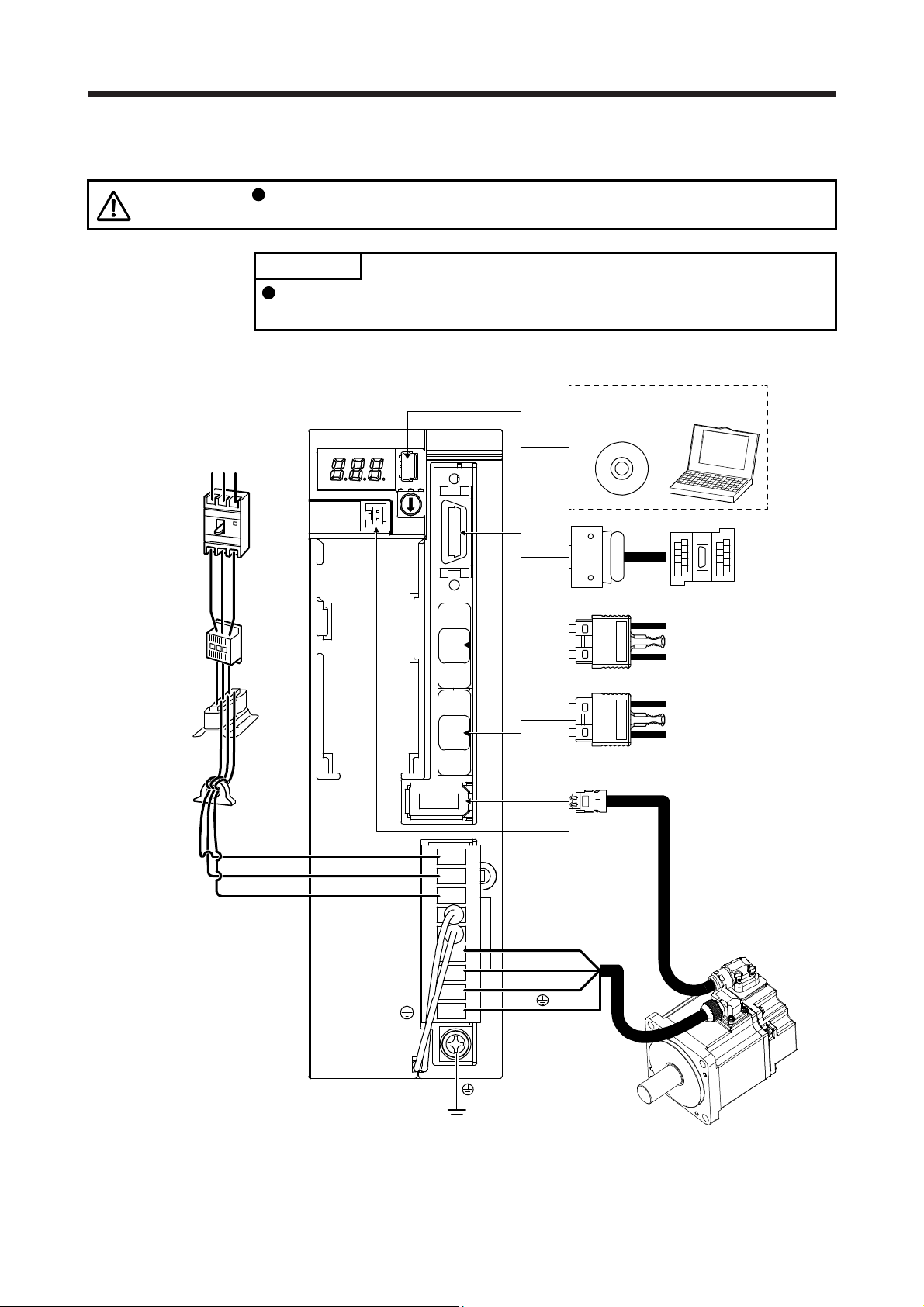
1.8 Configuration including peripheral equipment
CAUTION
(1) MR-JE-100B or less
The diagram shows MR-JE-40B.
(Note 1)
Power supply
Molded-case
circuit breaker
(MCCB)
RST
Connecting a servo motor of the wrong axis to U, V, W, or CN2 of the servo
amplifier may cause a malfunction.
POINT
Equipment other than the servo amplifier and servo motor are optional or
recommended products.
CN5
CN3
MR Configurator2
Personal
computer
Junction terminal
block
(Note 2)
Magnetic
contactor
(MC)
Power factor
improving AC
reactor (FR-HAL)
Line noise filter
(FR-BSF01)
L1
L2
L3
CN1A
CN1B
CN2
CN4
U
V
W
Battery
Servo system controller or
previous servo amplifier
CN1B
Next servo amplifier CN1A or
cap
Servo motor
Note 1. For 1-phase 200 V AC to 240 V AC, connect the power supply to L1 and L3. Leave L2 open. For the power supply
specifications, refer to section 1.3.
2. Depending on the power supply voltage and operation pattern, bus voltage can decrease. This can shift the mode to the
dynamic brake deceleration during forced stop deceleration. When dynamic brake deceleration is not required, slow the time to
turn off the magnetic contactor.
1 - 11
Page 27
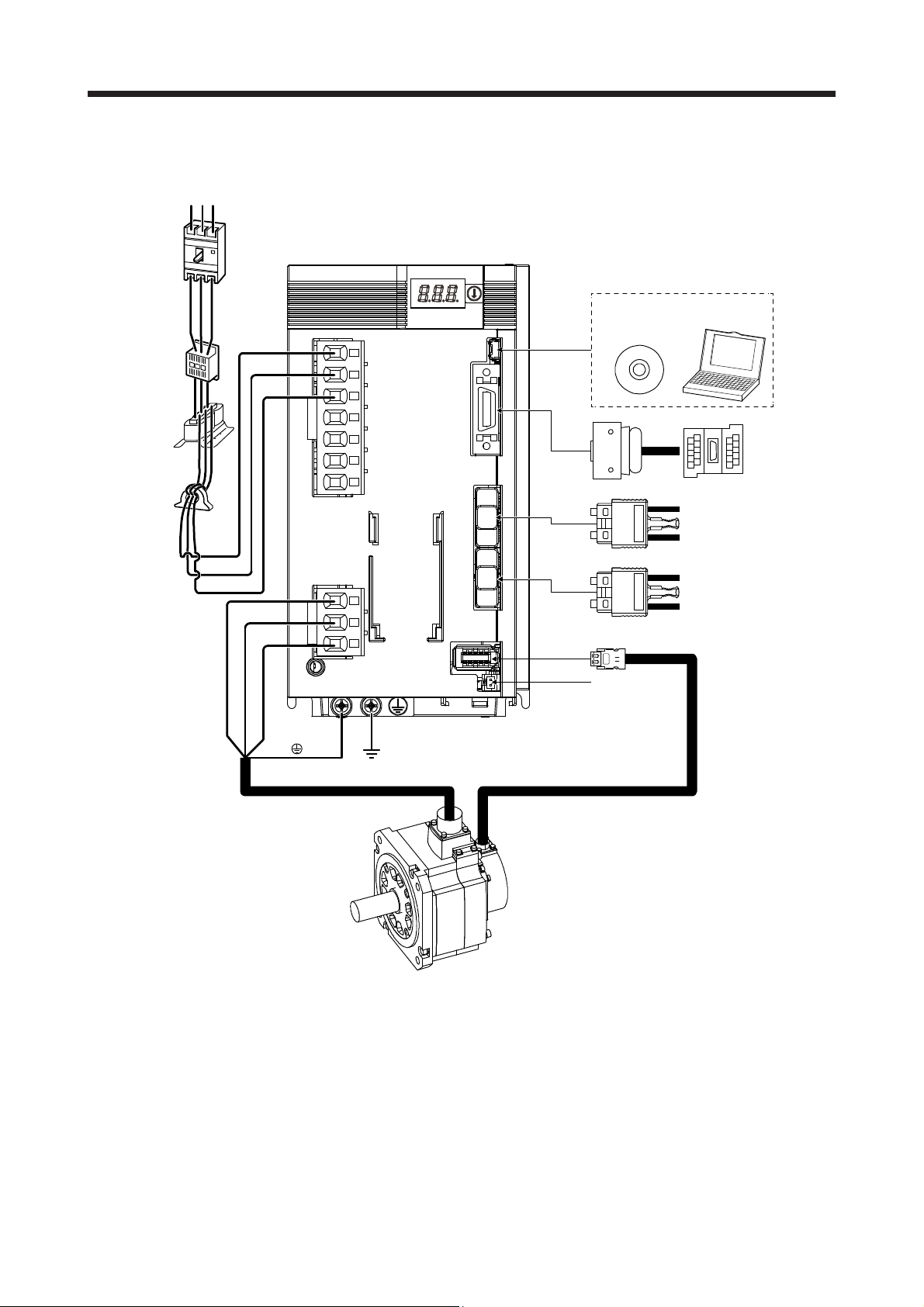
1. FUNCTIONS AND CONFIGURATION
(2) MR-JE-200B or more
The diagram shows MR-JE-200B.
(Note 1)
Power supply
Molded-case
circuit breaker
(MCCB)
(Note 2)
Magnetic
contactor
(MC)
Power factor
improving AC
reactor (FR-HAL)
Line noise filter
(FR-BSF01)
RS T
CN5
CN3
MR Configurator2
Personal
computer
Junction terminal
block
L1
L2
L3
CN1A
U
V
W
CN1B
CN2
CN4
Servo motor
Battery
Servo system controller or
previous servo amplifier
CN1B
Next servo amplifier CN1A or
cap
Note 1. A 1-phase 200 V AC to 240 V AC power supply may be used with the servo amplifier of MR-JE-200B. For 1-phase 200 V AC
to 240 V AC, connect the power supply to L1 and L2. Leave L3 open. For the power supply specifications, refer to section 1.3.
2. Depending on the power supply voltage and operation pattern, bus voltage can decrease. This can shift the mode to the
dynamic brake deceleration during forced stop deceleration. When dynamic brake deceleration is not required, slow the time to
turn off the magnetic contactor.
1 - 12
Page 28
2. INSTALLATION
2. INSTALLATION
WARNING
CAUTION
To prevent electric shock, ground each equipment securely.
Stacking in excess of the specified number of product packages is not allowed.
Do not hold the lead wire of the built-in regenerative resistor when transporting
the servo amplifier.
Install the equipment on incombustible material. Installing them directly or close to
combustibles will lead to a fire.
Install the servo amplifier and the servo motor in a load-bearing place in
accordance with the Instruction Manual.
Do not get on or put heavy load on the equipment. Otherwise, it may cause injury.
Use the equipment within the specified environment. For the environment, refer to
section 1.3.
Provide an adequate protection to prevent screws and other conductive matter, oil
and other combustible matter from entering the servo amplifier.
Do not block the intake and exhaust areas of the servo amplifier. Otherwise, it
may cause a malfunction.
Do not drop or strike the servo amplifier. Isolate it from all impact loads.
Do not install or operate the servo amplifier which has been damaged or has any
parts missing.
When the product has been stored for an extended period of time, contact your
local sales office.
When handling the servo amplifier, be careful about the edged parts such as
corners of the servo amplifier.
The servo amplifier must be installed in a metal cabinet.
When fumigants that contain halogen materials, such as fluorine, chlorine,
bromine, and iodine, are used for disinfecting and protecting wooden packaging
from insects, they cause malfunction when entering our products. Please take
necessary precautions to ensure that remaining materials from fumigant do not
enter our products, or treat packaging with methods other than fumigation, such
as heat treatment. Additionally, disinfect and protect wood from insects before
packing the products.
2 - 1
Page 29
2. INSTALLATION
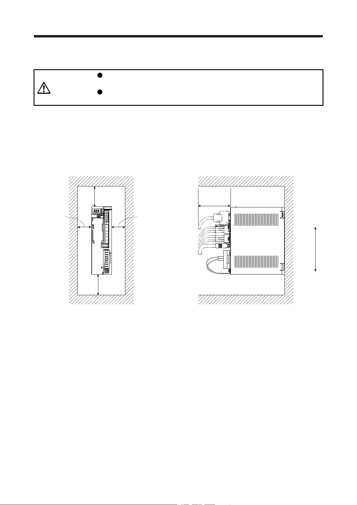
2.1 Installation direction and clearances
The equipment must be installed in the specified direction. Otherwise, it may
CAUTION
MR-JE-40B to MR-JE-100B have a regenerative resistor on their back face. The regenerative resistor
generates heat of 100 °C higher than the ambient temperature. Please fully consider heat dissipation,
installation position, etc. when installing the servo amplifier.
(1) Installation clearances of the servo amplifier
(a) Installation of one servo amplifier
cause a malfunction.
Leave specified clearances between the servo amplifier and the cabinet walls or
other equipment. Otherwise, it may cause a malfunction.
Cabinet Cabinet
10 mm
or more
40 mm
or more
Servo
amplifier
10 mm
or more
Wiring
allowance
80 mm
or more
Top
40 mm
or more
Bottom
2 - 2
Page 30
2. INSTALLATION
t
t
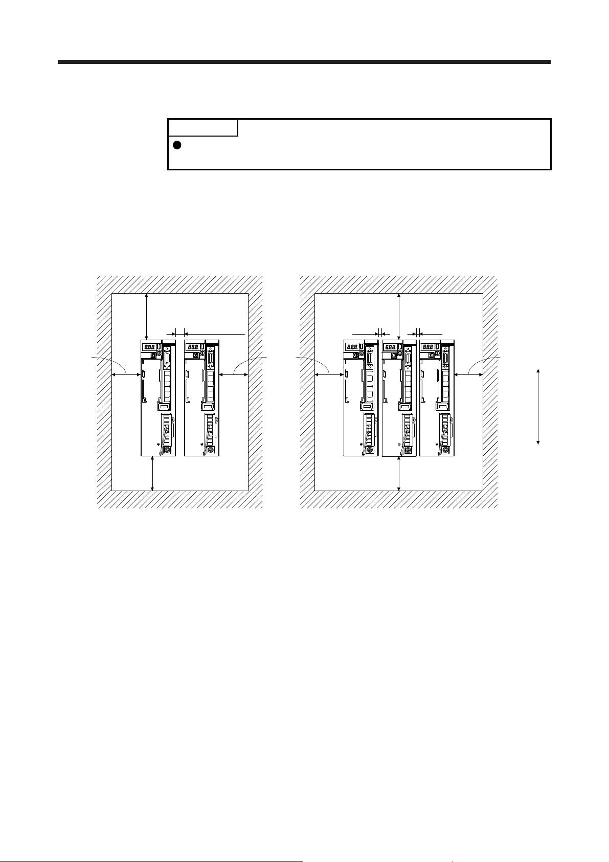
(b) Installation of two or more servo amplifiers
POINT
Close mounting is possible depending on the capacity of the servo amplifier.
Refer to section 1.3 for availability of close mounting.
Leave a large clearance between the top of the servo amplifier and the cabinet walls, and install a
cooling fan to prevent the internal temperature of the cabinet from exceeding the environment.
When mounting the servo amplifiers closely, leave a clearance of 1 mm between the adjacent servo
amplifiers in consideration of mounting tolerances. In this case, keep the ambient temperature within
0 ˚C to 45 ˚C or use the servo amplifier with 75% or lower of the effective load ratio.
Cabine
Cabine
30 mm
or more
100 mm or more
10 mm or more
30 mm
or more
40 mm or more
Leaving clearance Mounting closely
1 mm
100 mm or more
1 mm
40 mm or more
(2) Others
When using heat generating equipment such as the regenerative option, install them with full
consideration of heat generation so that the servo amplifier is not affected.
Install the servo amplifier on a perpendicular wall in the correct vertical direction.
2.2 Keep out foreign materials
30 mm
or more
Top
Bottom
(1) When drilling the cabinet, prevent drill chips and wire fragments from entering the servo amplifier.
(2) Prevent oil, water, metallic dust, etc. from entering the servo amplifier through openings in the cabinet or
a cooling fan installed on the ceiling.
(3) When installing the cabinet in a place where toxic gas, dirt, and dust exist, conduct an air purge (force
clean air into the cabinet from outside to make the internal pressure higher than the external pressure) to
prevent such materials from entering the cabinet.
2 - 3
Page 31

2. INSTALLATION
2.3 Encoder cable stress
(1) The way of clamping the cable must be fully examined so that bending stress and cable's own weight
stress are not applied to the cable connection.
(2) For use in any application where the servo motor moves, fix the cables (encoder, power supply, and
brake) with having some slack from the connector connection part of the servo motor to avoid putting
stress on the connector connection part. Use the optional encoder cable within the bending life range.
Use the power supply and brake wiring cables within the bending life of the cables.
(3) Avoid any probability that the cable sheath might be cut by sharp chips, rubbed by a machine corner, or
stamped by workers or vehicles.
(4) For installation on a machine where the servo motor moves, the flexing radius should be made as large
as possible. Refer to section 10.4 for the bending life.
2.4 SSCNET III cable laying
The SSCNET III cable is made from optical fiber. If power such as a major shock, lateral pressure, haul,
sudden bending, or twist is applied to the optical fiber, its inside distorts or breaks, and optical transmission
will not be available. Especially, as the optical fiber for MR-J3BUS_M/MR-J3BUS_M-A is made of synthetic
resin, it melts down if being left near the fire or high temperature. Therefore, do not make it touch the part
that can become hot such as heat sink or regenerative option of the servo amplifier.
Read described item of this section carefully and handle the SSCNET III cable with caution.
(1) Minimum bending radius
Make sure to lay the cable with greater radius than the minimum bending radius. Do not press the cable
to edges of equipment or others. For the SSCNET III cable, the appropriate length should be selected
with due consideration for the dimensions and arrangement of the servo amplifier. When closing the
door of the cabinet, pay careful attention to avoid the case that the SSCNET III cable is held down by the
door and the cable bend becomes smaller than the minimum bending radius. For the minimum bending
radius, refer to section 11.1.2.
(2) Prohibition of vinyl tape use
Migrating plasticizer is used for vinyl tape. Keep the MR-J3BUS_M, and MR-J3BUS_M-A cables away
from vinyl tape because the optical characteristic may be affected.
Optical cord
Cable
SSCNET III cable Cord Cable
MR-J3BUS_M
MR-J3BUS_M-A
MR-J3BUS_M-B
: Phthalate ester plasticizer such as DBP and DOP
may affect optical characteristic of the cable.
: The cord and cable are not basically affected by
plasticizer.
2 - 4
Page 32

2. INSTALLATION
r
(3) Precautions for migrating plasticizer added materials
Generally, soft polyvinyl chloride (PVC), polyethylene resin (PE), and fluorine resin contain nonmigrating plasticizer and they do not affect the optical characteristic of the SSCNET III cable. However,
some wire sheaths and cable ties that contain migrating plasticizer (phthalate ester) may affect MRJ3BUS_M and MR-J3BUS_M-A cables (plastic).
In addition, the MR-J3BUS_M-B cable (silica glass) is not affected by plasticizer.
A chemical substance may affect its optical characteristic. Therefore, previously check that the cable is
not affected by the environment.
(4) Bundle fixing
Fix the cable at the closest part to the connector with bundle material in order to prevent the SSCNET III
cable from putting its own weight on the CN1A/CN1B connector of the servo amplifier. The optical cord
should be given loose slack to avoid becoming smaller than the minimum bending radius, and it should
not be twisted.
When bundling the cable, fix and hold it in position by using cushioning such as sponge or rubber which
does not contain migratable plasticizers.
If adhesive tape for bundling the cable is used, fire resistant acetate cloth adhesive tape 570F (Teraoka
Seisakusho Co., Ltd) is recommended.
Connecto
Optical cord
Loose slack
Bundle material
Recommended product: NK clamp SP type
(NIX, INC)
Cable
(5) Tension
If tension is added on an optical cable, the increase of transmission loss occurs because of external
force which concentrates on the fixing part of the optical fiber or the connecting part of the optical
connector. Doing so may cause the breakage of the optical fiber or damage of the optical connector. For
cable laying, handle the cable without putting forced tension. For the tension strength, refer to section
11.1.2.
(6) Lateral pressure
If lateral pressure is added on an optical cable, the optical cable itself distorts, the internal optical fiber
gets stressed, and then transmission loss will increase. Doing so may cause the breakage of the optical
cable. As the same condition also occurs at cable laying, do not tighten up the optical cable with a thing
such as nylon band (TY-RAP).
Do not trample it down or tuck it down with the door of the cabinet or others.
2 - 5
Page 33

2. INSTALLATION
(7) Twisting
If optical fiber is twisted, it will become the same stress added condition as when local lateral pressure or
bend is added. Consequently, transmission loss increases, and the breakage of the optical fiber may
occur.
(8) Disposal
When the optical cable (cord) used for an SSCNET III cable, hydrogen fluoride gas or hydrogen chloride
gas which is corrosive and harmful may be generated. For disposal of optical fiber, request for
specialized industrial waste disposal services who has incineration facility for disposing hydrogen
fluoride gas or hydrogen chloride gas.
2.5 Inspection items
Before starting maintenance and/or inspection, turn off the power and wait for 15
minutes or more until the charge lamp turns off. Otherwise, an electric shock may
WARNING
CAUTION
It is recommended that the following points periodically be checked.
(1) Check for loose terminal block screws. Retighten any loose screws.
(2) Check for scratches and cracks of cables and the like. Inspect them periodically according to operating
conditions especially when the servo motor is movable.
(3) Check that the connector is securely connected to the servo amplifier.
(4) Check that the wires are not coming out from the connector.
(5) Check for dust accumulation on the servo amplifier.
(6) Check for unusual noise generated from the servo amplifier.
occur. In addition, when confirming whether the charge lamp is off or not, always
confirm it from the front of the servo amplifier.
To avoid an electric shock, only qualified personnel should attempt inspections.
For repair and parts replacement, contact your local sales office.
Do not perform insulation resistance test on the servo amplifier. Otherwise, it may
cause a malfunction.
Do not disassemble and/or repair the equipment on customer side.
2 - 6
Page 34

2. INSTALLATION
2.6 Parts having service lives
Service lives of the following parts are listed below. However, the service life varies depending on operating
methods and environment. If any fault is found in the parts, they must be replaced immediately regardless of
their service lives. For parts replacement, please contact your local sales office.
(1) Smoothing capacitor
The characteristic of a smoothing capacitor is deteriorated due to ripple currents, etc. The life of the
capacitor greatly depends on ambient temperature and operating conditions. The capacitor will reach
the end of its life in 10 years of continuous operation in normal air-conditioned environment (40 ˚C
surrounding air temperature or lower).
(2) Relays
Contact faults will occur due to contact wear arisen from switching currents. Relays will reach the end of
their lives depending on their power supply capacity when the number of power-on times, number of
forced stop times by EM1 (Forced stop 1), and number of controller forced stop times are 100,000 times
in total.
(3) Servo amplifier cooling fan
The cooling fan bearings reach the end of their lives in 10,000 hours to 30,000 hours. Normally,
therefore, the cooling fan must be replaced in a few years of continuous operation as a guideline. It must
also be changed if unusual noise or vibration is found during inspection.
The life indicates under the yearly average ambient temperature of 40 ˚C, free from corrosive gas,
flammable gas, oil mist, dust, and dirt.
Part name Life guideline
Smoothing capacitor 10 years
Number of power-on, forced stop by EM1
Relay
Cooling fan
Absolute position battery Refer to section 12.2.
(Forced stop 1), and controller forced stop
times: 100 000 times
50,000 hours to 70,000 hours
(7 years to 8 years)
2 - 7
Page 35

2. INSTALLATION
MEMO
2 - 8
Page 36

3. SIGNALS AND WIRING
3. SIGNALS AND WIRING
Any person who is involved in wiring should be fully competent to do the work.
Before wiring, turn off the power and wait for 15 minutes or more until the charge
lamp turns off. Otherwise, an electric shock may occur. In addition, when
confirming whether the charge lamp is off or not, always confirm it from the front
of the servo amplifier.
WARNING
Ground the servo amplifier and servo motor securely.
Do not attempt to wire the servo amplifier and servo motor until they have been
installed. Otherwise, it may cause an electric shock.
The cables should not be damaged, stressed, loaded, or pinched. Otherwise, it
may cause an electric shock.
To avoid an electric shock, insulate the connections of the power supply
terminals.
Before removing the CNP1 connector from MR-JE-40B to MR-JE-100B,
disconnect the lead wires of the regenerative resistor from the CNP1 connector.
Wire the equipment correctly and securely. Otherwise, the servo motor may
operate unexpectedly, resulting in injury.
Connect cables to the correct terminals. Otherwise, a burst, damage, etc. may
occur.
Ensure that polarity (+/-) is correct. Otherwise, a burst, damage, etc. may occur.
The surge absorbing diode installed to the DC relay for control output should be
fitted in the specified direction. Otherwise, the emergency stop and other
protective circuits may not operate.
CAUTION
Servo amplifier
DOCOM
Control output
signal
For sink output interface
24 V DC
RA
Servo amplifier
24 V DC
DOCOM
Control output
signal
For source output interface
RA
Use a noise filter, etc. to minimize the influence of electromagnetic interference.
Electromagnetic interference may be given to the electronic equipment used near
the servo amplifier.
Do not install a power capacitor, surge killer, or radio noise filter (optional FR-BIF)
with the power line of the servo motor.
When using a regenerative resistor, switch power off with the alarm signal.
Otherwise, a transistor fault or the like may overheat the regenerative resistor,
causing a fire.
Do not modify the equipment.
3 - 1
Page 37

3. SIGNALS AND WIRING
Connect the servo amplifier power output (U, V, and W) to the servo motor power
input (U, V, and W) directly. Do not let a magnetic contactor, etc. intervene.
Otherwise, it may cause a malfunction.
CAUTION
Connecting a servo motor of the wrong axis to U, V, W, or CN2 of the servo
amplifier may cause a malfunction.
3.1 Input power supply circuit
Always connect a magnetic contactor between the power supply and the power
supply (L1, L2, and L3) of the servo amplifier, in order to configure a circuit that
shuts down the power supply on the side of the servo amplifier’s power supply. If
a magnetic contactor is not connected, continuous flow of a large current may
cause a fire when the servo amplifier malfunctions.
Use an alarm to switch power off. Not doing so may cause a fire when a
regenerative transistor malfunction or the like may overheat the regenerative
resistor.
Before removing the CNP1 connector from MR-JE-40B to MR-JE-100B,
disconnect the lead wires of the regenerative resistor from the CNP1 connector.
Not doing so may break the lead wires of the regenerative resistor.
CAUTION
Check the servo amplifier model, and then input proper voltage to the servo
amplifier power supply. If input voltage exceeds the upper limit of the
specification, the servo amplifier will break down.
The servo amplifier has a built-in surge absorber (varistor) to reduce noise and to
suppress lightning surge. The varistor can break down due to its aged
deterioration. To prevent a fire, use a molded-case circuit breaker or fuse for input
power supply.
Connecting a servo motor of the wrong axis to U, V, W, or CN2 of the servo
amplifier may cause a malfunction.
N- terminal is not a neutral point of the power supply. Incorrect wiring may cause
a burst, damage, etc.
EM2 has the same function as EM1 in the torque control mode.
When a 1-phase 200 V AC to 240 V AC power supply is used, the connection
destination differs depending on the servo amplifier. Ensure that the connection
destination is correct.
Servo amplifier
U
V
W
POINT
Servo motor
U
V
W
U
M
V
W
Servo motorServo amplifier
U
V
M
W
Configure the wiring so that the power supply is shut off and the servo-on command is turned off after
deceleration to a stop due to an alarm occurring, an enabled servo forced stop, or an enabled controller
forced stop. A molded-case circuit breaker (MCCB) must be used with the input cables of the power supply.
3 - 2
Page 38

3. SIGNALS AND WIRING
(1) For 3-phase 200 V AC to 240 V AC power supply of MR-JE-10B to MR-JE-100B
EMG stop switch
MC (Note 8)
(Note 1)
OFF
Servo amplifier
CNP1
L1
Built-in
L2
regenerative
resistor
L3
P+
C
(Note 5)
Alarm
ON
U
V
W
MC
MC
SK
(Note 4, 7)
3-phase
200 V AC to
240 V AC
POINT
For MR-JE-_B servo amplifiers, the hot line forced stop function is enabled at
factory setting. For MR-J4-_B servo amplifiers, the hot line forced stop function
is disabled at factory setting.
If an alarm occurs, the hot line forced stop function outputs hot line forced stop
signals to all servo amplifiers before a communication to the controller is cut.
Then, servo amplifiers will be in the [AL. E7.1 Controller forced stop warning]
state and will decelerate to a stop.
The hot line forced stop function can be disabled with [Pr. PA27].
Configure the power supply circuit which turns off magnetic contactors of all
servo amplifiers after detection of alarm occurrence on the controller side at
alarm occurrence.
MCCB
Servo motor
U
V
W
Motor
M
(Note 3)
Forced stop 2
(Note 6)
Power
supply
24 V DC (Note 9)
CN3
EM2
DICOM
(Note 7)
CN2
CN3
DOCOM
MBR
(Note 2)
Encoder cable
24 V DC (Note 9)
RA1
Encoder
Electromagnetic
brake interlock
(Note 3)
3 - 3
Page 39

3. SIGNALS AND WIRING
Note 1. MR-JE-40B to MR-JE-100B have a built-in regenerative resistor. (factory-wired) When using the regenerative option, refer to
section 11.2.
2. For the encoder cable, use of the option cable is recommended. For cable selection, refer to "HG-KN_/HG-SN_ Servo Motor
Instruction Manual".
3. This diagram is for the sink I/O interface. For source I/O interface, refer to section 3.8.3.
4. For connection of servo motor power wires, refer to "HG-KN_/HG-SN_ Servo Motor Instruction Manual".
5. Configure the power supply circuit that turns off the magnetic contactor after an alarm occurs on the controller side.
6. Configure a circuit to turn off EM2 when the power is turned off to prevent an unexpected restart of the servo amplifier.
7. Connecting a servo motor of the wrong axis to U, V, W, or CN2 of the servo amplifier may cause a malfunction.
8. Use a magnetic contactor with an operation delay time (interval since a current is applied to the coil until the contact closes) of
80 ms or shorter. Depending on the power supply voltage and operation pattern, bus voltage can decrease. This can shift the
mode to the dynamic brake deceleration during forced stop deceleration. When dynamic brake deceleration is not required,
slow the time to turn off the magnetic contactor.
9. The illustration of the 24 V DC power supply is divided between input signal and output signal for convenience. However, they
can be configured by one.
3 - 4
Page 40

3. SIGNALS AND WIRING
(2) For 1-phase 200 V AC to 240 V AC power supply of MR-JE-10B to MR-JE-100B
POINT
For MR-JE-_B servo amplifiers, the hot line forced stop function is enabled at
factory setting. For MR-J4-_B servo amplifiers, the hot line forced stop function
is disabled at factory setting.
If an alarm occurs, the hot line forced stop function outputs hot line forced stop
signals to all servo amplifiers before a communication to the controller is cut.
Then, servo amplifiers will be in the [AL. E7.1 Controller forced stop warning]
state and will decelerate to a stop.
The hot line forced stop function can be disabled with [Pr. PA27].
Configure the power supply circuit which turns off magnetic contactors of all
servo amplifiers after detection of alarm occurrence on the controller side at
alarm occurrence.
Connect the 1-phase 200 V AC to 240 V AC power supply to L1 and L3. One of
the connecting destinations is different from MR-JE-200B Servo Amplifier's.
MCCB
1-phase
200 V AC to
240 V AC
EMG stop switch
MC (Note 8)
(Note 1)
OFF
Servo amplifier
CNP1
L1
Built-in
L2
regenerative
resistor
L3
P+
C
(Note 5)
Alarm
ON
U
V
W
MC
MC
SK
(Note 4, 7)
Servo motor
U
V
W
Motor
M
(Note 3)
Forced stop 2
(Note 6)
Power
supply
24 V DC (Note 9)
CN3
EM2
DICOM
(Note 7)
CN2
CN3
DOCOM
MBR
(Note 2)
Encoder cable
24 V DC (Note 9)
RA1
Encoder
Electromagnetic
brake interlock
(Note 3)
3 - 5
Page 41

3. SIGNALS AND WIRING
Note 1. MR-JE-40B to MR-JE-100B have a built-in regenerative resistor. (factory-wired) When using the regenerative option, refer to
section 11.2.
2. For the encoder cable, use of the option cable is recommended. For cable selection, refer to "HG-KN_/HG-SN_ Servo Motor
Instruction Manual".
3. This diagram is for the sink I/O interface. For source I/O interface, refer to section 3.8.3.
4. For connection of servo motor power wires, refer to "HG-KN_/HG-SN_ Servo Motor Instruction Manual".
5. Configure the power supply circuit that turns off the magnetic contactor after an alarm occurs on the controller side.
6. Configure a circuit to turn off EM2 when the power is turned off to prevent an unexpected restart of the servo amplifier.
7. Connecting a servo motor of the wrong axis to U, V, W, or CN2 of the servo amplifier may cause a malfunction.
8. Use a magnetic contactor with an operation delay time (interval since a current is applied to the coil until the contact closes) of
80 ms or shorter. Depending on the power supply voltage and operation pattern, bus voltage can decrease. This can shift the
mode to the dynamic brake deceleration during forced stop deceleration. When dynamic brake deceleration is not required,
slow the time to turn off the magnetic contactor.
9. The illustration of the 24 V DC power supply is divided between input signal and output signal for convenience. However, they
can be configured by one.
3 - 6
Page 42

3. SIGNALS AND WIRING
(3) For 3-phase 200 V AC to 240 V AC power supply of MR-JE-200B or MR-JE-300B
EMG stop switch
MC (Note 8)
(Note 1)
OFF
Servo amplifier
CNP1
L1
L2
L3
NC
D
P+
(Note 5)
Alarm
CNP2
ON
U
V
W
MC
MC
SK
(Note 4, 7)
3-phase
200 V AC to
240 V AC
POINT
For MR-JE-_B servo amplifiers, the hot line forced stop function is enabled at
factory setting. For MR-J4-_B servo amplifiers, the hot line forced stop function
is disabled at factory setting.
If an alarm occurs, the hot line forced stop function outputs hot line forced stop
signals to all servo amplifiers before a communication to the controller is cut.
Then, servo amplifiers will be in the [AL. E7.1 Controller forced stop warning]
state and will decelerate to a stop.
The hot line forced stop function can be disabled with [Pr. PA27].
Configure the power supply circuit which turns off magnetic contactors of all
servo amplifiers after detection of alarm occurrence on the controller side at
alarm occurrence.
MCCB
Servo motor
U
V
W
Motor
M
(Note 3)
Forced stop 2
(Note 6)
Power
supply
24 V DC (Note 9)
CN3
EM2
DICOM
(Note 7)
CN2
CN3
DOCOM
MBR
(Note 2)
Encoder cable
24 V DC (Note 9)
RA1
Encoder
Electromagnetic
brake interlock
(Note 3)
3 - 7
Page 43

3. SIGNALS AND WIRING
Note 1. Always connect between P+ and D terminals. (factory-wired) When using the regenerative option, refer to section 11.2.
2. For the encoder cable, use of the option cable is recommended. For cable selection, refer to "HG-KN_/HG-SN_ Servo Motor
Instruction Manual".
3. This diagram is for the sink I/O interface. For source I/O interface, refer to section 3.8.3.
4. For connection of servo motor power wires, refer to "HG-KN_/HG-SN_ Servo Motor Instruction Manual".
5. Configure the power supply circuit that turns off the magnetic contactor after an alarm occurs on the controller side.
6. Configure a circuit to turn off EM2 when the power is turned off to prevent an unexpected restart of the servo amplifier.
7. Connecting a servo motor of the wrong axis to U, V, W, or CN2 of the servo amplifier may cause a malfunction.
8. Use a magnetic contactor with an operation delay time (interval since a current is applied to the coil until the contact closes) of
80 ms or shorter. Depending on the power supply voltage and operation pattern, bus voltage can decrease. This can shift the
mode to the dynamic brake deceleration during forced stop deceleration. When dynamic brake deceleration is not required,
slow the time to turn off the magnetic contactor.
9. The illustration of the 24 V DC power supply is divided between input signal and output signal for convenience. However, they
can be configured by one.
3 - 8
Page 44

3. SIGNALS AND WIRING
(4) For 1-phase 200 V AC to 240 V AC power supply of MR-JE-200B
EMG stop switch
MC (Note 8)
(Note 1)
OFF
Servo amplifier
CNP1
L1
L2
L3
NC
D
P+
ON
(Note 5)
Alarm
CNP2
U
V
W
1-phase
200 V AC to
240 V AC
POINT
For MR-JE-_B servo amplifiers, the hot line forced stop function is enabled at
factory setting. For MR-J4-_B servo amplifiers, the hot line forced stop function
is disabled at factory setting.
If an alarm occurs, the hot line forced stop function outputs hot line forced stop
signals to all servo amplifiers before a communication to the controller is cut.
Then, servo amplifiers will be in the [AL. E7.1 Controller forced stop warning]
state and will decelerate to a stop.
The hot line forced stop function can be disabled with [Pr. PA27].
Configure the power supply circuit which turns off magnetic contactors of all
servo amplifiers after detection of alarm occurrence on the controller side at
alarm occurrence.
Connect the 1-phase 200 V AC to 240 V AC power supply to L1 and L2. One of
the connecting destinations is different from MR-JE-100B or less Servo
Amplifier's.
MCCB
MC
MC
SK
(Note 4, 7)
Servo motor
U
V
W
Motor
M
(Note 3)
Forced stop 2
(Note 6)
Power
supply
24 V DC (Note 9)
CN3
EM2
DICOM
(Note 7)
CN2
CN3
DOCOM
MBR
(Note 2)
Encoder cable
24 V DC (Note 9)
RA1
Encoder
Electromagnetic
brake interlock
(Note 3)
3 - 9
Page 45

3. SIGNALS AND WIRING
Note 1. Always connect between P+ and D terminals. (factory-wired) When using the regenerative option, refer to section 11.2.
2. For the encoder cable, use of the option cable is recommended. For cable selection, refer to "HG-KN_/HG-SN_ Servo Motor
Instruction Manual".
3. This diagram is for the sink I/O interface. For source I/O interface, refer to section 3.8.3.
4. For connection of servo motor power wires, refer to "HG-KN_/HG-SN_ Servo Motor Instruction Manual".
5. Configure the power supply circuit that turns off the magnetic contactor after an alarm occurs on the controller side.
6. Configure a circuit to turn off EM2 when the power is turned off to prevent an unexpected restart of the servo amplifier.
7. Connecting a servo motor of the wrong axis to U, V, W, or CN2 of the servo amplifier may cause a malfunction.
8. Use a magnetic contactor with an operation delay time (interval since a current is applied to the coil until the contact closes) of
80 ms or shorter. Depending on the power supply voltage and operation pattern, bus voltage can decrease. This can shift the
mode to the dynamic brake deceleration during forced stop deceleration. When dynamic brake deceleration is not required,
slow the time to turn off the magnetic contactor.
9. The illustration of the 24 V DC power supply is divided between input signal and output signal for convenience. However, they
can be configured by one.
3 - 10
Page 46

3. SIGNALS AND WIRING
r
3.2 I/O signal connection example
POINT
EM2 has the same function as EM1 in the torque control mode.
3.2.1 For sink I/O interface
10 m or less
(Note 3, 4)
Forced stop 2
Servo system
controller
(Note 5)
MR Configurator2
+
SSCNET III cable
(Note 12)
Power supply
(Note 10) 24 V DC
(Note 6)
(option)
Personal
computer
MR-J3USBCBL3M
USB cable
(option)
DICOM
Servo amplifie
CN3
20EM2
10
CN5
(Note 6)
SSCNET III cable
(option)
CN3
13 MBR
CN1BCN1A
24 V DC (Note 10)
DOCOM
3
(Note 1)
10 m or less
(Note 2)
RA1
The last servo amplifier (Note 8)
(Note 9)
Cap
Electromagnetic brake
interlock
Servo amplifier
CN1A
CN1B
CN1A
CN1B
(Note 11)
(Note 7)
(Note 7)
Note 1. To prevent an electric shock, always connect the protective earth (PE) terminal (marked with ) of the servo amplifier to the
protective earth (PE) of the cabinet.
2. Connect the diode in the correct direction. If it is connected reversely, the servo amplifier will malfunction and will not output
signals, disabling EM2 (Forced stop 2) and other protective circuits.
3. If the controller does not have a forced stop function, always install the forced stop 2 switch (normally closed contact).
4. When starting operation, always turn on EM2 (Forced stop 2). (normally closed contact)
5. Use SW1DNC-MRC2-E. (Refer to section 11.4.)
6. Use SSCNET III cables listed in the following table.
Cable Cable model Cable length
Standard cord inside
cabinet
Standard cable
outside cabinet
Long distance cable MR-J3BUS_M-B 30 m to 50 m
MR-J3BUS_M 0.15 m to 3 m
MR-J3BUS_M-A 5 m to 20 m
7. The wiring after the second servo amplifier is omitted.
8. Up to 16 axes of servo amplifiers can be connected. The number of connectable axes depends on the controller you use.
Refer to section 4.3.1 for setting of axis selection.
9. Make sure to cap the unused CN1B connector.
10. Supply 24 V DC ± 10% to interfaces from outside. The total current capacity of these power supplies must be 100 mA or lower.
The current capacity 100 mA is applicable when all I/O signals are used. The current capacity can be decreased by reducing
the number of I/O points. Refer to section 3.8.2 that gives the current value necessary for the interface. The illustration of the
24 V DC power supply is divided between input signal and output signal for convenience. However, they can be configured by
one.
11. You can change a device assigned to the CN3-13 pin with [Pr. PD07].
12. Configure a circuit to turn off EM2 when the power is turned off to prevent an unexpected restart of the servo amplifier.
3 - 11
Page 47

3. SIGNALS AND WIRING
3.2.2 For source I/O interface
POINT
For notes, refer to section 3.2.1.
10 m or less
(Note 3, 4)
Forced stop 2
Servo system
controller
MR Configurator2
+
SSCNET III cable
(Note 12)
Power supply
(Note 10) 24 V DC
(Note 6)
(option)
Personal
computer(Note 5)
MR-J3USBCBL3M
USB cable
(option)
DICOM
Servo amplifier
CN3 CN3
20EM2
10
CN5
(Note 6)
SSCNET III cable
(option)
3
13 MBR
CN1BCN1A
10 m or less
24 V DC (Note 10)
DOCOM
(Note 1)
(Note 2)
The last servo amplifier (Note 8)
(Note 9)
Cap
RA1
Servo amplifier
CN1A
CN1B
CN1A
CN1B
Electromagnetic brake
interlock
(Note 7)
(Note 7)
(Note 11)
3 - 12
Page 48

3. SIGNALS AND WIRING
3.3 Explanation of power supply system
3.3.1 Signal explanations
POINT
For the layout of the connector and terminal block, refer to chapter 9
DIMENSIONS.
Connection
Symbol
destination
(application)
Supply the following power to L1, L2, and L3. For 1-phase 200 V AC to 240 V AC of MR-JE-10B to
MR-JE-100B, connect the power supply to L1 and L3. Leave L2 open.
For 1-phase 200 V AC to 240 V AC of MR-JE-200B, connect the power supply to L1 and L2. Leave
L3 open.
Description
L1/L2/L3 Power supply
P+/C/D
U/V/W
N-
Regenerative
option
Servo motor
power output
Protective earth
(PE)
Servo amplifier
Power supply
3-phase 200 V AC to 240 V AC,
50 Hz/60 Hz
1-phase 200 V AC to 240 V AC,
50 Hz/60 Hz
1) MR-JE-100B or less
MR-JE-10B to MR-JE-100B do not have D.
When using a servo amplifier built-in regenerative resistor, connect it to P+ and C. (factory-
wired)
MR-JE-10B and MR-JE-20B do not have a built-in regenerative resistor.
When using a regenerative option, disconnect wires of the built-in regenerative resistor from P+
and C. Then, connect wires of the regenerative option to P+ and C.
2) MR-JE-200B or more
When using a servo amplifier built-in regenerative resistor, connect P+ and D. (factory-wired)
When using a regenerative option, disconnect P+ and D, and connect the regenerative option to
P+ and C.
Refer to section 11.2 for details.
Connect the terminals to the servo motor power supply terminals (U, V, and W). Connect the servo
amplifier power output (U, V, and W) to the servo motor power input (U, V, and W) directly. Do not
let a magnetic contactor, etc. intervene. Otherwise, it may cause a malfunction.
This terminal is for manufacturer adjustment.
Leave this terminal open.
MR-JE-10B to MR-JE-100B do not have N-.
Connect this terminal to the grounding terminal of the servo motor and to the protective earth (PE)
of the cabinet for grounding.
MR-JE-10B to
MR-JE-100B
L1/L2/L3
L1/L3 L1/L2
MR-JE-200B MR-JE-300B
3 - 13
Page 49

3. SIGNALS AND WIRING
3.3.2 Power-on sequence
POINT
The output signal, etc. may be unstable at power-on.
(1) Power-on procedure
(a) Always use a magnetic contactor for the power supply wiring (L1, L2, and L3) as shown in above
section 3.1. Configure the power supply circuit that turns off the magnetic contactor after an alarm
occurs on the controller side.
(b) The servo amplifier receives the servo-on command within 3 s to 4 s after the power supply is
switched on.
(Refer to (2) of this section.)
(2) Timing chart
Power supply
Base circuit
Servo-on command
(from controller)
Servo-on command accepted
(3 s to 4 s)
ON
OFF
ON
OFF
ON
OFF
95 ms
10 ms 95 ms
3 - 14
Page 50

3. SIGNALS AND WIRING
r
3.3.3 Wiring CNP1 and CNP2
POINT
For the wire sizes used for wiring, refer to section 11.6.
For the wiring to CNP1 and CNP2, use servo amplifier power connectors packed with the amplifier or
optional connectors (refer to section 11.1.1).
(1) Connector
(a) MR-JE-10B to MR-JE-100B
Servo amplifie
CNP1
Connector Receptacle assembly
CNP1 09JFAT-SAXGDK-H5.0 AWG 18 to 14 3.9 mm or shorter 9 J-FAT-OT JST
(b) MR-JE-200B/MR-JE-300B
Connector Receptacle assembly
CNP1 07JFAT-SAXGFK-XL
CNP2 03JFAT-SAXGFK-XL
Table 3.1 Connector and applicable wire
Applicable wire
Size Insulator OD
Servo amplifier
CNP1
CNP2
Table 3.2 Connector and applicable wire
Applicable wire
Size Insulator OD
AWG 16 to 10 4.7 mm or shorter 11.5 J-FAT-OT-EXL JST
Stripped
length [mm]
Stripped
length [mm]
Open tool
Open tool
Manu-
facturer
Manu-
facturer
3 - 15
Page 51

3. SIGNALS AND WIRING
r
(2) Cable connection procedure
(a) Fabrication on cable insulator
Refer to table 3.1 and 3.2 for stripped length of the cable insulator. The appropriate stripped length
of cables depends on their type, etc. Set the length considering their status.
Twist strands lightly and straighten them as follows.
Insulato
Stripped length
Core
You can also use a ferrule for connection with the connectors. When using a ferrule, select a ferrule
and crimping tool listed in the table below.
(b) Inserting wire
Insert the open tool as follows and push down it to open the spring. While the open tool is pushed
down, insert the stripped wire into the wire insertion hole. Check the insertion depth so that the wire
insulator does not get caught by the spring.
Release the open tool to fix the wire. Pull the wire lightly to confirm that the wire is surely connected.
The following shows a connection example of the CNP2 connector for 2 kW and 3 kW.
Servo amplifier Wire size
MR-JE-10B to
MR-JE-100B
MR-JE-200B to
MR-JE-300B
AWG 16 AI1.5-10BK AI-TWIN2 × 1.5-10BK
AWG 14 AI2.5-10BU
AWG 16 AI1.5-10BK AI-TWIN2 × 1.5-10BK
AWG 14 AI2.5-10BU AI-TWIN2 × 2.5-10BU
AWG 12 AI4-10GY
Loose and bent strands Twist and straighten
Ferrule model (Phoenix Contact)
For one For two
1) Push down the open tool.
the strands.
Crimp terminal
(Phoenix Contact)
CRIMPFOX-ZA3
3) Release the open tool to fix the wire.
2) Insert the wire.
3 - 16
Page 52

3. SIGNALS AND WIRING
3.4 Connectors and pin assignment
POINT
The pin assignment of the connectors is as viewed from the cable connector
wiring section.
For the CN3 connector, securely connect the external conductor of the shielded
cable to the ground plate and fix it to the connector shell.
Screw
Cable
Screw
Ground plate
The servo amplifier front view shown is that of the MR-JE-40B or less. Refer to chapter 9 DIMENSIONS for
the appearances and connector layouts of the other servo amplifiers.
CN5 (USB connector)
Refer to section 11.4.
CN3
1
2
3
4
DOCOM
5
6
7
8
12
14
16
18
11
13
MBR
15
17
CN2
2
LG 8
1
P5
4
MRR
3
MR
6
MDR
5
MD
CN4
(Battery connector)
Refer to section 11.5.
10
9
BAT
7
CN1A
Connector for SSCNET III
cable for previous servo
amplifier axis
CN1B
Connector for SSCNET III
cable for next servo
amplifier axis
The frames of the CN2 and CN3
connectors are connected to the
protective earth terminal in the
servo amplifier.
9
10
DICOM
19
20
EM2
3 - 17
Page 53

3. SIGNALS AND WIRING
3.5 Signal (device) explanations
For the I/O interfaces (symbols in I/O division column in the table), refer to section 3.8.2.
The pin numbers in the connector pin number column are those in the initial status.
3.5.1 Input device
Connector
Device Symbol
Forced stop 2 EM2 CN3-20
Forced stop 1 EM1 (CN3-20)
pin
number
Function and application
Turn off EM2 (open between commons) to decelerate the servo motor to a stop
with commands.
Turn EM2 on (short between commons) in the forced stop state to reset that
state.
Set [Pr. PA04] to "2 1 _ _" to disable EM2.
The following shows the setting of [Pr. PA04].
[Pr. PA04]
setting
EM2 or EM1 is off Alarm occurred
0 0 _ _ EM1
2 0 _ _ EM2
0 1 _ _
2 1 _ _
EM2 and EM1 are mutually exclusive.
Note that EM2 has the same function as EM1 in the torque control mode.
When using EM1, set [Pr. PA04] to "0 0 _ _" to enable EM1.
Turn EM1 off (open between commons) to bring the motor to a forced stop
state. The base circuit is shut off, and the dynamic brake is operated and
decelerates the servo motor to a stop.
Turn EM1 on (short between commons) in the forced stop state to reset that
state.
Set [Pr. PA04] to "0 1 _ _" to disable EM1.
EM2/EM1
Not using
EM2 or
EM1
Not using
EM2 or
EM1
MBR (Electromagnetic
brake interlock) turns off
without the forced stop
deceleration.
MBR (Electromagnetic
brake interlock) turns off
after the forced stop
deceleration.
Deceleration method
MBR (Electromagnetic
brake interlock) turns off
without the forced stop
deceleration.
MBR (Electromagnetic
brake interlock) turns off
after the forced stop
deceleration.
MBR (Electromagnetic
brake interlock) turns off
without the forced stop
deceleration.
MBR (Electromagnetic
brake interlock) turns off
after the forced stop
deceleration.
I/O
division
DI-1
DI-1
3 - 18
Page 54

3. SIGNALS AND WIRING
3.5.2 Output device
(1) Output device pin
The following shows the output device pins and parameters for assigning devices.
(2) Output device explanations
Device Symbol Function and application
Electromagnetic
brake interlock
Malfunction ALM When the protective circuit is activated to shut off the base circuit, ALM will turn off.
In-position INP When the number of droop pulses is in the in-position range, INP will turn on. The in-position range
Ready RD Enabling servo-on to make the servo amplifier ready to operate will turn on RD.
Speed reached SA SA will turn off during servo-off. When the servo motor speed reaches the following range, SA will
Limiting speed VLC When the speed reaches the speed limit value in the torque control mode, VLC will turn on. When
Zero speed detection ZSP ZSP turns on when the servo motor speed is zero speed (50 r/min) or slower. Zero speed can be
MBR When using the device, set operation delay time of the electromagnetic brake in [Pr. PC02].
When a servo-off status or alarm occurs, MBR will turn off.
When an alarm does not occur, ALM will turn on after 2.5 s to 3.5 s after power-on.
can be changed using [Pr. PA10]. When the in-position range is increased, INP may be on during
low-speed rotation.
The device cannot be used in the speed control mode or torque control mode or for continuous
operation to torque control mode.
turn on.
Preset speed ± ((Preset speed × 0.05) + 20) r/min
When the preset speed is 20 r/min or slower, SA always turns on.
The device cannot be used in the position control mode and torque control mode.
the servo is off, TLC will be turned off.
The device cannot be used in the position control mode and speed control mode.
changed with [Pr. PC07].
Connector pin
number
CN3-13 [Pr. PD07] MBR DO-1
Parameter Initial device I/O division
Forward
rotation
direction
Servo motor
speed
Reverse
rotation
direction
ZSP
(Zero speed
detection)
ZSP will turn on when the servo motor is decelerated to 50 r/min (at 1)), and will turn off when the
servo motor is accelerated to 70 r/min again (at 2)).
ZSP will turn on when the servo motor is decelerated again to 50 r/min (at 3)), and will turn off
when the servo motor speed has reached -70 r/min (at 4)).
The range from the point when the servo motor speed has reached on level, and ZSP turns on, to
the point when it is accelerated again and has reached off level is called hysteresis width.
Hysteresis width is 20 r/min for this servo amplifier.
OFF level
70 r/min
ON level
50 r/min
0 r/min
ON level
-50 r/min
OFF level
-70 r/min
ON
OFF
1)
3)
2)
4)
20 r/min
(Hysteresis width)
[Pr. PC07]
[Pr. PC07]
20 r/min
(Hysteresis width)
3 - 19
Page 55

3. SIGNALS AND WIRING
Device Symbol Function and application
Limiting torque TLC When the torque reaches the torque limit value during torque generation, TLC will turn on. When
the servo is off, TLC will be turned off.
This device cannot be used in the torque control mode.
Warning WNG When a warning has occurred, WNG turns on. When a warning is not occurring, turning on the
power will turn off WNG after 2.5 s to 3.5 s.
Battery warning BWNG BWNG turns on when [AL. 92 Battery cable disconnection warning] or [AL. 9F Battery warning] has
occurred. When the battery warning is not occurring, turning on the power will turn off BWNG after
2.5 s to 3.5 s.
Variable gain
selection
Absolute position
undetermined
During tough drive MTTR When a tough drive is "Enabled" in [Pr. PA20], activating the instantaneous power failure tough
3.5.3 Power supply
Signal name Symbol
Digital I/F power
supply input
Digital I/F common DOCOM CN3-3 Common terminal of input signal such as EM2 of the servo amplifier. This terminal is
Shield SD Plate Connect the external conductor of the shielded wire.
CDPS CDPS will turn on during variable gain.
ABSV ABSV turns on when the absolute position is undetermined.
The device cannot be used in the speed control mode and torque control mode.
drive will turn on MTTR.
Connector
pin
number
DICOM CN3-10 Input 24 V DC (24 V DC ± 10% 100 mA) for I/O interface. The power supply capacity
changes depending on the number of I/O interface points to be used.
For sink interface, connect + of 24 V DC external power supply.
For source interface, connect - of 24 V DC external power supply.
separated from LG.
For sink interface, connect - of 24 V DC external power supply.
For source interface, connect + of 24 V DC external power supply.
Function and application
3 - 20
Page 56

3. SIGNALS AND WIRING
3.6 Forced stop deceleration function
POINT
When alarms not related to the forced stop function occur, control of motor
deceleration cannot be guaranteed. (Refer to chapter 8.)
When SSCNET III/H communication brake occurs, forced stop deceleration will
operate. (Refer to section 3.7.1 (3).)
In the torque control mode, the forced stop deceleration function cannot be
used.
3.6.1 Forced stop deceleration function
When EM2 is turned off, dynamic brake will start to stop the servo motor after forced stop deceleration.
During this sequence, the display shows [AL. E6 Servo forced stop warning].
During normal operation, do not use EM2 (Forced stop 2) to alternate stop and drive. The servo amplifier life
may be shortened.
(1) Connection diagram
Servo amplifier
24 V DC
(Note)
Forced stop 2
Note. This diagram is for the sink I/O interface. For source I/O interface, refer to section
3.8.3.
DICOM
EM2
3 - 21
Page 57

3. SIGNALS AND WIRING
t
c
t
(2) Timing chart
When EM2 (Forced stop 2) turns off, the motor will decelerate according to [Pr. PC24 Forced stop
deceleration time constant]. Once the motor speed is below [Pr. PC07 Zero speed] after completion of
the deceleration command, base power is cut and the dynamic brake activates.
EM2 (Forced stop 2)
Rated Speed
Servo motor speed
Base circuit
(Energy supply to
he servo motor)
MBR
(Electromagneti
brake interlock)
ON
OFF (Enabled)
0 r/min
ON
OFF
ON
OFF (Enabled)
Ordinary
operation
Forced stop
deceleration
Command
Deceleration time
[Pr. PC24]
Dynamic brake
Electromagnetic brake
Zero speed
([Pr. PC07])
+
3.6.2 Base circuit shut-off delay time function
The base circuit shut-off delay time function is used to prevent a vertical axis from dropping at a forced stop
(EM2 goes off), alarm occurrence, or SSCNET III/H communication brake due to delay time of the
electromagnetic brake. Set the time from MBR (Electromagnetic brake interlock) off to base circuit shut-off
with [Pr. PC02].
(1) Timing chart
EM2 (Forced stop 2)
ON
OFF (Enabled)
When EM2 (Forced stop 2) turns off or an
alarm occurs during driving, the servo
motor will decelerate based on the
deceleration time constant. MBR
(Electromagnetic brake interlock) will turn
Servo motor speed
off, and then after the delay time set in [Pr.
PC02], the servo amplifier will be base
circuit shut-off status.
Base circuit
(Energy supply to
he servo motor)
MBR
(Electromagnetic
brake interlock)
0 r/min
ON
OFF
[Pr. PC02]
ON
OFF (Enabled)
3 - 22
Page 58

3. SIGNALS AND WIRING
(2) Adjustment
While the servo motor is stopped, turn off EM2 (Forced stop 2), adjust the base circuit shut-off delay
time in [Pr. PC02], and set the value to approximately 1.5 times of the smallest delay time in which the
servo motor shaft does not freefall.
3.6.3 Vertical axis freefall prevention function
The vertical axis freefall prevention function prevents machine damage by pulling up the shaft slightly like the
following case.
When the servo motor is used for operating vertical axis, the servo motor electromagnetic brake and the
base circuit shut-off delay time function prevent dropping axis at forced stop. However, the functions may not
prevent dropping axis a few μm due to the backlash of the servo motor electromagnetic brake.
The vertical axis freefall prevention function is enabled with the following conditions.
Other than "0" is set to [Pr. PC31 Vertical axis freefall prevention compensation amount].
EM2 (Forced stop 2) turns off, an alarm occurs, or SSCNET III/H communication brake occurs while the
servo motor speed is zero speed or slower.
The base circuit shut-off delay time function is enabled.
(1) Timing chart
EM2 (Forced stop 2)
ON
OFF (Enabled)
Position
Base circuit
(Energy supply to
the servo motor)
MBR
(Electromagnetic
brake interlock)
Actual operation of
electromagnetic
brake
Travel distance
ON
OFF
ON
OFF (Enabled)
Disabled
Enabled
Set the base circuit shut-off delay time. ([Pr. PC02])
(2) Adjustment
Set the freefall prevention compensation amount in [Pr. PC31].
While the servo motor is stopped, turn off the EM2 (Forced stop 2). Adjust the base circuit shut-off
delay time in [Pr. PC02] in accordance with the travel distance ([Pr. PC31]). Adjust it considering the
freefall prevention compensation amount by checking the servo motor speed, torque ripple, etc.
3.6.4 Residual risks of the forced stop function (EM2)
(1) The forced stop function is not activated by alarms that activate the dynamic brake when the alarms
occur.
(2) When an alarm that activates the dynamic brake during forced stop deceleration occurs, the braking
distance until the servo motor stops will be longer than that of normal forced stop deceleration without
the dynamic brake.
3 - 23
Page 59

3. SIGNALS AND WIRING
3.7 Alarm occurrence timing chart
When an alarm has occurred, remove its cause, make sure that the operation
CAUTION
To deactivate the alarm, cycle the power or give the error reset or CPU reset command from the servo
system controller. However, the alarm cannot be deactivated unless its cause is removed.
3.7.1 When you use the forced stop deceleration function
signal is not being input, ensure safety, and reset the alarm before restarting
operation.
POINT
In the torque control mode, the forced stop deceleration function cannot be
used.
POINT
To enable the function, set "2 _ _ _ (initial value)" in [Pr. PA04].
(1) When the forced stop deceleration function is enabled
Alarm occurrence
Servo motor speed
0 r/min
Base circuit
(Energy supply to
the servo motor)
Servo amplifier
display
MBR
(Electromagnetic
brake interlock)
ALM (Malfunction)
Note. The model speed command is a speed command generated in the servo amplifier for forced stop deceleration
of the servo motor.
ON
OFF
ON
OFF
ON (no alarm)
OFF (alarm)
Controller command is ignored.
Alarm No.No alarm
(Note)
Model speed command 0
and equal to or less than
zero speed
3 - 24
Page 60

3. SIGNALS AND WIRING
A
(2) When the forced stop deceleration function is not enabled
Alarm occurrence
Servo motor speed
Base circuit
(Energy supply to
the servo motor)
Servo amplifier
display
MBR
(Electromagnetic
brake interlock)
ALM (Malfunction)
Braking by the dynamic brake
0 r/min
ON
OFF
No alarm Alarm No.
ON
OFF
ON (no alarm)
OFF (alarm)
Dynamic brake
+ Braking by the electromagnetic brake
Operation delay time of the electromagnetic brake
(3) When SSCNET III/H communication brake occurs
The dynamic brake may operate depending on the communication shut-off status.
SSCNET III/H communication
Servo motor speed
has broken.
(Note)
Model speed command 0
and equal to or less than
zero speed
0 r/min
Base circuit
(Energy supply to
the servo motor)
Servo amplifier
display
MBR
(Electromagnetic
brake interlock)
LM (Malfunction)
Note. The model speed command is a speed command generated in the servo amplifier for forced stop deceleration
of the servo motor.
ON
OFF
AANo alarm (d1 or E7)
ON
OFF
ON (no alarm)
OFF (alarm)
3.7.2 When you do not use the forced stop deceleration function
POINT
To disable the function, set "0 _ _ _" in [Pr. PA04].
The timing chart that shows the servo motor condition when an alarm or SSCNET III/H communication brake
occurs is the same as section 3.7.1 (2).
3 - 25
Page 61

3. SIGNALS AND WIRING
3.7.3 Hot line forced stop function
POINT
When the power supply of the servo amplifier is shut off during deceleration to a
stop by a hot line forced stop signal, the servo motor will be stopped with the
dynamic brake.
For using the hot line forced stop function with MR-JE-_B servo amplifier and
MR-J4-_B servo amplifier together, refer to appendix 9 for the hot line forced
stop function of MR-J4-_B servo amplifiers.
(1) Summary
The hot line forced stop function enables all servo amplifiers to decelerate to a stop and them to stop
safely if an alarm occurs in a system configuration using MR-JE-_B servo amplifiers.
Since the power supply of the MR-JE-_B servo amplifier is commonly used for main circuit and control
circuit power supplies, if the power supply is shut off at occurrence of an alarm, servo amplifiers in which
the alarm occurred and later cannot communicate with the controller. Thus, if an alarm occurs, the
function outputs hot line forced stop signals to all servo amplifiers before a communication to the
controller is cut. Then, servo amplifiers will be in the [AL. E7.1 Controller forced stop warning] state and
will be stopped safely. Also, the function can be disabled with a parameter.
(2) Parameter setting
The hot line forced stop function is enabled at factory setting. Setting "_ _ _ 1" in [Pr. PA27] disables the
function.
(3) Operation description
If an alarm occurs in the second axis servo amplifier in a 4-axis system configuration, the operation will
be as follows.
Controller
Hot line alarm signal transmission (a)
The first axis
MR-JE-_B
The second axis
MR-JE-_B
The third axis
MR-JE-_B
The fourth axis
MR-JE-_B
Alarm
occurrence
Deceleration
to a stop (c)
Hot line forced stop signal transmission (b)
Deceleration
to a stop
Deceleration
to a stop (d)
(a) The servo amplifier in which an alarm occurs transmits the hot line alarm signal to the controller.
(b) Upon receipt of a hot line alarm signal, the controller transmits hot line forced stop signals to all
servo amplifiers.
(c) Upon receipt of a hot line forced stop signal from the controller, [AL. E7.1 Controller forced stop
warning] will occur, and normally operating servo amplifiers will decelerate to a stop. "E7.1" will be
shown on the display of the servo amplifier.
3 - 26
Deceleration
to a stop (d)
Page 62

3. SIGNALS AND WIRING
T
r
t
T
r
w
T
r
r
(d) When the power supply of a servo amplifier in which an alarm occurred is shut off, subsequent servo
amplifiers will decelerate to a stop, and the controller will be in a non-connection state. "AA" will be
shown on the display of the servo amplifier.
(4) Timing chart
(a) When the hot line forced stop function is enabled
1) If an alarm that leads to a deceleration to a stop occurs in the second axis servo amplifier, and
then the power supply is off
To clear [AL. E7.1 Controller forced stop warning], give the error reset command from the
controller.
Power off of the servo amplifier
Hot line alarm signal (from
he servo amplifier in which
an alarm occurred)
Hot line forced stop signal
(from the controller)
Input power
supply
Signal
No signal
ON
OFF
ON
OFF
Alarm occurrence
3.5 ms + communication cycle
in which an alarm occurred
he first axis
servo amplifie
he second axis
servo amplifie
(the servo
amplifier in
hich an alarm
occurred)
he third axis
servo amplifie
and late
Servo amplifier
display
Servo motor
speed
Input power
supply
Servo amplifier
display
Servo motor
speed
Input power
supply
Servo amplifier
display
Servo motor
speed
0 r/min
ON
OFF
0 r/min
ON
OFF
0 r/min
No alarm
Deceleration to a stop
No alarm Blank
No alarm E7.1
Alarm No.
Deceleration
to a stop
Deceleration to a stop
E7.1
Power on
duration
AA
3 - 27
Page 63

3. SIGNALS AND WIRING
2) If an alarm that stops the servo motor with the dynamic brake occurs in the second axis servo
amplifier, and then the power supply is off
To clear [AL. E7.1 Controller forced stop warning], give the error reset command from the
controller.
Hot line alarm signal (from
the servo amplifier in which
an alarm occurred)
Hot line forced stop signal
(from the controller)
Input power
supply
Signal
No signal
ON
OFF
ON
OFF
Alarm
occurrence
Power off of the servo amplifier
in which an alarm occurred
3.5 ms +
communication
cycle
The first axis
servo amplifier
The second axis
servo amplifier
(the servo
amplifier in
which an alarm
occurred)
The third axis
servo amplifier
and later
Servo amplifier
display
Servo motor
speed
Input power
supply
Servo amplifier
display
Servo motor
speed
Input power
supply
Servo amplifier
display
Servo motor
speed
0 r/min
ON
OFF
0 r/min
ON
OFF
0 r/min
No alarm
Deceleration to a stop
Power on
duration
No alarm Blank
No alarm E7.1
Alarm No.
Stop with dynamic brake
Deceleration
to a stop
E7.1
AA
3 - 28
Page 64

3. SIGNALS AND WIRING
3) When the power of the second axis servo amplifier is turned off
Hot line alarm signal (from
the servo amplifier whose
power is turned off)
Hot line forced stop signal
(from the controller)
Input power
supply
Signal
No signal
ON
OFF
ON
OFF
The first axis
servo amplifier
The second axis
servo amplifier
(the servo
amplifier whose
power is turned
off)
The third axis
servo amplifier
and later
Servo amplifier
display
Servo motor
speed
Input power
supply
Servo amplifier
display
Servo motor
speed
Input power
supply
Servo amplifier
display
Servo motor
speed
0 r/min
ON
OFF
0 r/min
ON
OFF
0 r/min
Power on duration
No alarm
No alarm
No alarm
Stop with dynamic brake
Deceleration
to a stop
Blank
AA
3 - 29
Page 65

3. SIGNALS AND WIRING
A
4) When power supplies of all servo amplifiers are turned off
Hot line alarm signal (from
the servo amplifier whose
power is turned off)
Hot line forced stop signal
(from the controller)
Input power
supply
Servo amplifier
ll servo
amplifiers
display
Signal
No signal
ON
OFF
ON
OFF
Power on duration
No alarm Blank
Servo motor
speed
0 r/min
(b) When the hot line forced stop function is disabled
1) If an alarm that leads to a deceleration to a stop occurs in the second axis servo amplifier, and
then the power supply is off
Hot line alarm signal (from
the servo amplifier in which
an alarm occurred)
Hot line forced stop signal
(from the controller)
Input power
supply
Servo amplifier
The first axis
servo amplifier
The second axis
servo amplifier
(the servo
amplifier in
which an alarm
occurred)
display
Servo motor
speed
Input power
supply
Servo amplifier
display
Servo motor
speed
Signal
No signal
ON
OFF
ON
OFF
0 r/min
ON
OFF
0 r/min
Alarm occurrence
No alarm BlankAlarm No.
Stop with dynamic brake
Power off of the servo amplifier
in which an alarm occurred
No alarm
Power on
duration
Deceleration
to a stop
ON
OFF
0 r/min
No alarm
Deceleration
to a stop
AA
The third axis
servo amplifier
and later
Input power
supply
Servo amplifier
display
Servo motor
speed
3 - 30
Page 66

3. SIGNALS AND WIRING
r
2) If an alarm that stops the servo motor with the dynamic brake occurs in the second axis servo
amplifier, and then the power supply is off
Hot line alarm signal (from
the servo amplifier in which
an alarm occurred)
Hot line forced stop signal
(from the controller)
Input power
supply
Signal
No signal
ON
OFF
ON
OFF
Alarm
occurrence
Power off of the servo amplifie
in which an alarm occurred
The first axis
servo amplifier
The second axis
servo amplifier
(the servo
amplifier in
which an alarm
occurred)
The third axis
servo amplifier
and later
Servo amplifier
display
Servo motor
speed
Input power
supply
Servo amplifier
display
Servo motor
speed
Input power
supply
Servo amplifier
display
Servo motor
speed
0 r/min
ON
OFF
0 r/min
ON
OFF
0 r/min
No alarm
Power on duration
No alarm Blank
Alarm No.
No alarm
Stop with dynamic brake
Deceleration
to a stop
AA
3) When the power of the second axis servo amplifier is turned off
It is the same as (4) (a) 3) in this section.
4) When power supplies of all servo amplifiers are turned off
It is the same as (4) (a) 4) in this section.
3 - 31
Page 67

3. SIGNALS AND WIRING
3.8 Interfaces
3.8.1 Internal connection diagram
CN3
20
10
Approximately
(Note 1)
Forced stop 2
(Note 2)
24 V DC
EM2
DICOM
6.2 kΩ
Servo amplifier
CN3
3
13
DOCOM
MBR
(Note 2)
24 V DC
RA
(Note 1)
Isolated
Servo motor
CN5
D- 2
USB
Note 1. This diagram is for the sink I/O interface. For source I/O interface, refer to section 3.8.3.
2. The illustration of the 24 V DC power supply is divided between input signal and output signal for convenience. However, they
can be configured by one.
D+
GND
3
5
CN2
7
8
3
4
2
MD
MDR
MR
MRR
LG
PE
Encoder
M
3 - 32
Page 68

3. SIGNALS AND WIRING
3.8.2 Detailed explanation of interfaces
This section provides the details of the I/O signal interfaces (refer to the I/O division in the table) given in
section 3.5. Refer to this section and make connection with the external device.
(1) Digital input interface DI-1
This is an input circuit whose photocoupler cathode side is the input terminal. Transmit signals from sink
(open-collector) type transistor output, relay switch, etc. The following is a connection diagram for sink
input. Refer to section 3.8.3 for source input.
For transistor
Approximately
5 mA
TR
V
1.0 V
CES
I
100 µA
CEO
Switch
24 V DC ± 10%
100 mA
Servo amplifier
EM2
Approximately
6.2 kΩ
DICOM
(2) Digital output interface DO-1
This is a circuit in which the collector of the output transistor is the output terminal. When the output
transistor is turned on, the current will flow from the collector terminal.
A lamp, relay, or photocoupler can be driven. Install a diode (D) for an inductive load, or install an inrush
current suppressing resistor (R) for a lamp load.
(Rated current: 40 mA or lower, maximum current: 50 mA or lower, inrush current: 100 mA or lower) A
maximum of 2.6 V voltage drop occurs in the servo amplifier.
The following shows a connection diagram for sink output. Refer to section 3.8.3 for source output.
Servo amplifier
If polarity of diode is
reversed, servo amplifier
MBR
DOCOM
Note. If the voltage drop (maximum of 2.6 V) interferes with the relay operation, apply high
voltage (maximum of 26.4 V) from an external source.
Load
(Note) 24 V DC ± 10%
100 mA
will malfunction.
3 - 33
Page 69

3. SIGNALS AND WIRING
3.8.3 Source I/O interfaces
In this servo amplifier, source type I/O interfaces can be used.
(1) Digital input interface DI-1
This is an input circuit in which the anode of the photocoupler is the input terminal. Transmit signals from
source (open-collector) type transistor output, relay switch, etc.
For transistor
TR
Approximately
5 mA
V
1.0 V
CES
I
100 µA
CEO
Switch
24 V DC ± 10%
100 mA
(2) Digital output interface DO-1
This is a circuit in which the emitter of the output transistor is the output terminal. When the output
transistor is turned on, the current will flow from the output terminal to a load.
A maximum of 2.6 V voltage drop occurs in the servo amplifier.
Servo amplifier
Servo amplifier
EM2
Approximately
6.2 kΩ
DICOM
If polarity of diode is
reversed, servo amplifier
MBR
DOCOM
Note. If the voltage drop (maximum of 2.6 V) interferes with the relay operation, apply high
voltage (maximum of 26.4 V) from an external source.
Load
(Note) 24 V DC ± 10%
100 mA
will malfunction.
3 - 34
Page 70

3. SIGNALS AND WIRING
r
r
r
3.9 SSCNET III cable connection
POINT
Do not look directly at the light generated from the CN1A/CN1B connector of the
servo amplifier or the end of the SSCNET III cable. The light can be a discomfort
when it enters the eye.
(1) SSCNET III cable connection
For the CN1A connector, connect the SSCNET III cable connected to a controller in host side or a servo
amplifier of the previous axis. For the CN1B connector, connect the SSCNET III cable connected to the
servo amplifier of the next axis. For the CN1B connector of the final axis, put a cap came with the servo
amplifier.
The first axis servo amplifie
The second axis servo amplifie
The last axis servo amplifie
SSCNET III cable
Controller
(2) How to connect/disconnect cable
POINT
The CN1A and CN1B connectors are capped to protect light devices inside the
connector from dust. For this reason, do not remove a cap until just before
mounting an SSCNET III cable. Then, when removing the SSCNET III cable,
make sure to put a cap.
Keep the cap for the CN1A/CN1B connector and the tube for protecting the
optical cord end of an SSCNET III cable in a plastic bag with a zipper of the
SSCNET III cable to prevent them from becoming dirty.
When asking repair of the servo amplifier for some malfunctions, make sure to
cap the CN1A and CN1B connectors. When the connector is not capped, the
light device may be damaged at the transit. In this case, replacing and repairing
the light device are required.
CN1A
CN1B
SSCNET III
cable
CN1A
CN1B
SSCNET III
cable
CN1A
CN1B
Cap
3 - 35
Page 71

3. SIGNALS AND WIRING
r
r
(a) Connection
1) For an SSCNET III cable in the shipping status, the tube for protecting the optical cord end is put
on the end of connector. Remove this tube.
2) Remove the CN1A and CN1B connector caps of the servo amplifier.
3) While holding a tab of the SSCNET III cable connector, make sure to insert it into the CN1A and
CN1B connectors of the servo amplifier until you hear the click. If the end face of the optical cord
tip is dirty, optical transmission is interrupted and it may cause malfunctions. If it becomes dirty,
wipe with a bonded textile, etc. Do not use solvent such as alcohol.
Servo amplifie
Servo amplifie
Click
(b) Disconnection
While holding a tab of the SSCNET III cable connector, pull out the connector.
When pulling out the SSCNET III cable from the servo amplifier, be sure to put the cap on the
connector parts of the servo amplifier to prevent them from becoming dirty. For the SSCNET III
cable, attach the tube for protecting the optical cord's end face on the end of the connector.
Tab
CN1A
CN1B
CN1A
CN1B
3 - 36
Page 72

3. SIGNALS AND WIRING
3.10 Servo motor with an electromagnetic brake
3.10.1 Safety precautions
Configure an electromagnetic brake circuit so that it is activated also by an
external EMG stop switch.
Contacts must be opened when ALM (Malfunction)
or MBR (Electromagnetic brake interlock) turns off.
Electromagnetic brake
Servo motor
B
Contacts must be opened with the
EMG stop switch.
RA
U
24 V DC
CAUTION
for ordinary braking.
Before operating the servo motor, be sure to confirm that the electromagnetic
brake operates properly.
Do not use the 24 V DC interface power supply for the electromagnetic brake.
Always use the power supply designed exclusively for the electromagnetic brake.
Otherwise, it may cause a malfunction.
When using EM2 (Forced stop 2), use MBR (Electromagnetic brake interlock) for
operating the electromagnetic brake. Operating the electromagnetic brake without
using MBR during deceleration to a stop will saturate servo motor torques at the
maximum value due to brake torque of the electromagnetic brake. This can result
The electromagnetic brake is provided for holding purpose and must not be used
in delay of the deceleration to a stop from a set value.
POINT
Refer to "HG-KN_/HG-SN_ Servo Motor Instruction Manual" for specifications
such as the power supply capacity and operation delay time of the
electromagnetic brake.
Refer to "HG-KN_/HG-SN_ Servo Motor Instruction Manual" for the selection of
a surge absorber for the electromagnetic brake.
Note the following when the servo motor with an electromagnetic brake is used.
1) The brake will operate when the power (24 V DC) turns off.
2) Turn off the servo-on command after the servo motor stopped.
(1) Connection diagram
Servo amplifier
DOCOM
MBR
(Note 2)
24 V DC
RA1
24 V DC
MBR
RA1
(Note 3)
(Note 1)
B1
U
Servo motor
B
B2
Note 1. Create the circuit in order to shut off by interlocking with the emergency stop switch.
2. Do not use the 24 V DC interface power supply for the electromagnetic brake.
3. Create the circuit in order to shut off by interlocking with an alarm detected by the controller.
3 - 37
Page 73

3. SIGNALS AND WIRING
(2) Setting
In [Pr. PC02 Electromagnetic brake sequence output], set a delay time (Tb) from MBR (Electromagnetic
brake interlock) off to base circuit shut-off at a servo-off as in the timing chart in section 3.10.2.
3.10.2 Timing chart
(1) When you use the forced stop deceleration function
POINT
To enable the function, set "2 _ _ _ (initial value)" in [Pr. PA04].
(a) Servo-on command (from controller) on/off
When the servo-on command is turned off, the servo lock will be released after Tb [ms], and the
servo motor will coast. If the electromagnetic brake is enabled during servo-lock, the brake life may
be shorter. Therefore, set Tb about 1.5 times of the minimum delay time where the moving part will
not drop down for a vertical axis system, etc.
Tb [Pr. PC02 Electromagnetic brake sequence output]
Coasting
Operation delay time of
the electromagnetic brake
(Note 1)
0 r/min
ON
OFF
ON
OFF
ON
OFF
ON
OFF
0 r/min
Release
Activate
Approx. 95 ms
Approx. 95 ms
(Note 3)
Release delay time and external relay, etc. (Note 2)
Servo motor speed
Base circuit
MBR
(Electromagnetic
brake interlock)
Servo-on command
(from controller)
Ready-on command
(from controller)
Operation command
(from controller)
Electromagnetic
brake
Note 1. ON: The electromagnetic brake is not activated.
OFF: The electromagnetic brake is activated.
2. The electromagnetic brake is released after the release delay time of the electromagnetic brake and operation time of the
external circuit relay, etc. For the release delay time of the electromagnetic brake, refer to "Servo Motor Instruction Manual
(Vol. 3)".
3. Give the operation command from the controller after the electromagnetic brake is released.
3 - 38
Page 74

3. SIGNALS AND WIRING
A
(b) Off/on of the forced stop command (from controller) or EM2 (Forced stop 2)
POINT
In the torque control mode, the forced stop deceleration function cannot be
used.
Servo motor speed
0 r/min
(Note 2)
Model speed command 0
and equal to or less than
zero speed
Base circuit
(Energy supply to
the servo motor)
Forced stop command
(from controller) or EM2
(Forced stop 2)
MBR
(Electromagnetic
brake interlock)
LM (Malfunction)
Note 1. ON: The electromagnetic brake is not activated.
2. The model speed command is a speed command generated in the servo amplifier for forced stop
(c) Alarm occurrence
The operation status during an alarm is the same as section 3.7.
(d) Power off
ON
OFF
Disabled (ON)
Enabled (OFF)
ON
(Note 1)
OFF
ON (no alarm)
OFF (alarm)
OFF: The electromagnetic brake is activated.
deceleration of the servo motor.
Servo motor speed
0 r/min
(Note 2)
ON
OFF
ON
OFF
No alarm
Alarm
Base circuit
MBR
(Electromagnetic
brake interlock)
Alarm
[AL.10 Undervoltage]
Approx. 10 ms
(Note 1)
Dynamic brake
Dynamic brake
+ Electromagnetic brake
Electromagnetic brake
Operation delay time of
the electromagnetic brake
Power supply
Note 1. Variable according to the operation status.
2. ON: The electromagnetic brake is not activated.
OFF: The electromagnetic brake is activated.
ON
OFF
3 - 39
Page 75

3. SIGNALS AND WIRING
(e) Ready-off command from controller
Servo motor speed
0 r/min
Approx. 10 ms
Dynamic brake
Dynamic brake
+ Electromagnetic brake
Electromagnetic brake
(Note)
ON
OFF
ON
OFF
ON
OFF
Base circuit
MBR
(Electromagnetic
brake interlock)
Ready-on command
(from controller)
Note. ON: The electromagnetic brake is not activated.
OFF: The electromagnetic brake is activated.
(2) When you do not use the forced stop deceleration function
POINT
To disable the function, set "0 _ _ _" in [Pr. PA04].
(a) Servo-on command (from controller) on/off
It is the same as (1) (a) in this section.
(b) Off/on of the forced stop command (from controller) or EM1 (Forced stop 1)
Dynamic brake
Dynamic brake
+ Electromagnetic brake
Servo motor speed
Base circuit
MBR
(Electromagnetic
brake interlock)
Forced stop command
(from controller)
or
EM1 (Forced stop 1)
0 r/min
(Note)
ON
OFF
ON
OFF
Disabled (ON)
Enabled (OFF)
Electromagnetic brake
Approx. 10 ms
Operation delay time
of the electromagnetic
brake
Operation delay time of
the electromagnetic brake
Electromagnetic brake
has released.
Approx. 210 ms
Approx. 210 ms
Note. ON: The electromagnetic brake is not activated.
OFF: The electromagnetic brake is activated.
(c) Alarm occurrence
The operation status during an alarm is the same as section 3.7.
(d) Power off
It is the same as (1) (d) of this section.
(e) Ready-off command from controller
It is the same as (1) (e) in this section.
3 - 40
Page 76

3. SIGNALS AND WIRING
3.11 Grounding
Ground the servo amplifier and servo motor securely.
WARNING
The servo amplifier switches the power transistor on-off to supply power to the servo motor. Depending on
the wiring and ground cable routing, the servo amplifier may be affected by the switching noise (due to di/dt
and dv/dt) of the transistor. To prevent such a fault, refer to the following diagram and always ground.
To conform to the EMC Directive, refer to the EMC Installation Guidelines (IB(NA)67310).
(Note)
Power
supply
To prevent an electric shock, always connect the protective earth (PE) terminal
(marked with
MCCB
) of the servo amplifier to the protective earth (PE) of the cabinet.
Cabinet
Servo amplifier
CN2
Line filter
MC
L1
L2
L3
Servo motor
Encoder
CN1A
Protective earth (PE)
controller
Servo system
W
U
V
Outer
box
U
M
V
W
Ensure to connect the wire to
the PE terminal of the servo
amplifier. Do not connect the
wire directly to the grounding
of the cabinet.
Note. For the power supply specifications, refer to section 1.3.
3 - 41
Page 77

3. SIGNALS AND WIRING
MEMO
3 - 42
Page 78

4. STARTUP
4. STARTUP
WARNING
CAUTION
4.1 Switching power on for the first time
When switching power on for the first time, follow this section to make a startup.
4.1.1 Startup procedure
Do not operate the switches with wet hands. Otherwise, it may cause an electric
shock.
Before starting operation, check the parameters. Improper settings may cause
some machines to operate unexpectedly.
The servo amplifier heat sink, regenerative resistor, servo motor, etc. may be hot
while power is on or for some time after power-off. Take safety measures, e.g.
provide covers, to avoid accidentally touching the parts (cables, etc.) by hand.
During operation, never touch the rotor of the servo motor. Otherwise, it may
cause injury.
Wiring check
Surrounding environment check
Axis No. settings
Parameter setting
Test operation of the servo motor
alone in test operation mode
Test operation of the servo
motor alone by commands
Test operation with the servo
motor and machine connected
Gain adjustment
Actual operation
Stop
Check whether the servo amplifier and servo motor are wired correctly using
visual inspection, the DO forced output function (section 4.5.1), etc. (Refer to
section 4.1.2.)
Check the surrounding environment of the servo amplifier and servo motor.
(Refer to section 4.1.3.)
Confirm that the control axis No. set with the axis selection rotary switch
(SW1) and the control axis No. set with the servo system controller are
consistent. (Refer to section 4.3.1.)
As necessary, set parameters. (Refer to chapter 5.)
For the test operation, with the servo motor disconnected from the machine
and operated at the speed as low as possible, check whether the servo
motor rotates correctly. (Refer to section 4.5.)
For the test operation with the servo motor disconnected from the machine
and operated at the speed as low as possible, give commands to the servo
amplifier and check whether the servo motor rotates correctly.
After connecting the servo motor with the machine, check machine motions
with sending operation commands from the servo system controller.
Adjust gains to optimize the machine motions. (Refer to chapter 6.)
Stop giving commands and stop operation.
4 - 1
Page 79

4. STARTUP
r
r
4.1.2 Wiring check
(1) Power supply system wiring
Before switching on the power supply, check the following items.
(a) Power supply system wiring
The power supplied to the power input terminals (L1, L2, and L3) of the servo amplifier should satisfy
the defined specifications. (Refer to section 1.3.)
(b) Connection of the servo amplifier and servo motor
1) The servo amplifier power output (U, V, and W) should match in phase with the servo motor
power input terminals (U, V, and W).
Servo amplifie
U
V
W
2) The power supplied to the servo amplifier should not be connected to the power output (U, V, and
W). Doing so will cause failure of the connected servo amplifier and servo motor.
Servo moto
U
V
W
M
3) The grounding terminal of the servo motor is connected to the PE terminal of the servo amplifier.
Servo amplifier Servo motor
4) The CN2 connector of the servo amplifier should be connected to the encoder of the servo motor
securely using the encoder cable.
(c) When you use an option and peripheral equipment
1) When you use a regenerative option for 1 kW or less servo amplifiers
The built-in regenerative resistor and wirings should be removed from the servo amplifier.
The lead wire of the built-in regenerative resistor connected to the P+ terminal and C terminal
should not be connected.
The regenerative option should be connected to the P+ terminal and C terminal.
A twisted cable should be used. (Refer to section 11.2.4.)
2) When you use a regenerative option for 2 kW or more servo amplifiers
The lead wire between the P+ terminal and D terminal should not be connected.
The regenerative option should be connected to the P+ terminal and C terminal.
A twisted cable should be used. (Refer to section 11.2.4.)
Servo amplifier Servo motor
L1
L2
L3
U
V
W
U
V
M
W
M
4 - 2
Page 80

4. STARTUP
(2) I/O signal wiring
(a) The I/O signals should be connected correctly.
Use the DO forced output to forcibly turn on or off the pins of the CN3 connector. This function can
be used to check the wiring. At this time, check the wiring in the servo-off status.
4.1.3 Surrounding environment
(1) Cable routing
(2) Environment
Refer to section 3.2 for details of I/O signal connection.
(b) A voltage exceeding 24 V DC is not applied to the pins of the CN3 connector.
(c) The wire between the plate and DOCOM of the CN3 connector should not be shorted.
Servo amplifier
CN3
DOCOM
Plate
(a) The wiring cables should not be stressed.
(b) The encoder cable should not be used in excess of its bending life. (Refer to section 10.4.)
(c) The connector of the servo motor should not be stressed.
Signal cables and power cables are not shorted by wire offcuts, metallic dust, or the like.
4 - 3
Page 81

4. STARTUP
4.2 Startup
Connect the servo motor with a machine after confirming that the servo motor operates properly alone.
(1) Power on
When the power supply is turned on, "b01" (for the first axis) appears on the servo amplifier display.
When you use the absolute position detection system, first power-on results in [AL. 25 Absolute position
erased] and the servo system cannot be switched on. The alarm can be deactivated by switching power
off once and on again.
Also, if power is switched on at the servo motor speed of 3000 r/min or faster, a position mismatch may
occur due to external force or the like. Power must therefore be switched on when the servo motor is at
a stop.
(2) Parameter setting
POINT
The following encoder cables are of four-wire type. When using any of these
encoder cables, set [Pr. PC04] to "1 _ _ _" to select the four-wire type. An
incorrect setting will result in [AL. 16 Encoder initial communication error 1].
MR-EKCBL30M-L
MR-EKCBL30M-H
MR-EKCBL40M-H
MR-EKCBL50M-H
Set the parameters according to the structure and specifications of the machine. Refer to chapter 5 for
details.
After setting the above parameters, turn off the power as necessary. Then switch power on again to
enable the parameter values.
(3) Servo-on
Enable the servo-on with the following procedure.
(a) Switch on the power.
(b) Transmit the servo-on command with the servo system controller.
When the servo-on status is enabled, the servo amplifier is ready to operate and the servo motor is
locked.
(4) Home position return
Always perform home position return before starting positioning operation.
4 - 4
Page 82

4. STARTUP
(5) Stop
If any of the following situations occurs, the servo amplifier suspends the running of the servo motor and
brings it to a stop.
Refer to section 3.10 for the servo motor with an electromagnetic brake.
Servo system
controller
Servo amplifier
Note. Only a list of alarms and warnings is listed in chapter 8. Refer to "MELSERVO-JE Servo Amplifier
4.3 Switch setting and display of the servo amplifier
Operation and command Stopping condition
Servo-off command The base circuit is shut off and the servo motor coasts.
Ready-off command
Forced stop command
Alarm occurrence
EM2 (Forced stop 2) off
Instruction Manual (Troubleshooting)" for details of alarms and warnings.
The base circuit is shut off and the dynamic brake operates to
bring the servo motor to a stop.
The servo motor decelerates to a stop with the command. [AL.
E7 Controller forced stop warning] occurs.
The servo motor decelerates to a stop with the command. With
some alarms, however, the dynamic brake operates to bring the
servo motor to a stop. (Refer to chapter 8. (Note))
The servo motor decelerates to a stop with the command. [AL.
E6 Servo forced stop warning] occurs. EM2 has the same
function as that of EM1 in the torque control mode.
The control axis No. can be set with switches on the servo amplifier.
On the servo amplifier display (three-digit, seven-segment LED), check the status of communication with the
servo system controller at power-on and the axis number, and diagnose a malfunction at occurrence of an
alarm.
4.3.1 Axis selection rotary switch (SW1)
When switching the axis selection rotary switch (SW1), use an insulated screw
WARNING
driver. Do not use a metal screw driver. Touching patterns on electronic boards,
lead of electronic parts, etc. may cause an electric shock.
POINT
The control axis No. set to the axis selection rotary switch (SW1) should be the
same as the one set to the servo system controller. The number of the axes you
can set depends on the servo system controller.
For setting the axis selection rotary switch, use a flat head screwdriver with the
blade edge width of 2.1 mm to 2.3 mm and the blade edge thickness of 0.6 mm
to 0.7 mm.
Cycling the power supply enables the setting of the switch.
4 - 5
Page 83

4. STARTUP
A
The control axis No. can be set in the range of 1 to 16 with the axis selection rotary switch.a t
If the same numbers are set to different control axes in a single communication system, the system will not
operate properly. The control axes may be set independently of the SSCNET III cable connection sequence.
Table 4.1 shows control axis numbers corresponding to the axis selection rotary switch to set the control axis
number.
xis selection rotary switch (SW1)
8
9
7
6
5
4
3
2
Table 4.1 Switch combination list for the control axis No. setting
Axis selection rotary switch (SW1) Control axis No.
0 1
1 2
2 3
3 4
4 5
5 6
6 7
7 8
8 9
9 10
A 11
B 12
C 13
D 14
E 15
F 16
A
B
C
D
E
F
1
0
4 - 6
Page 84

4. STARTUP
4.3.2 Scrolling display
(1) Normal display
When there is no alarm, the axis No. and blank are displayed in rotation.
After 1.6 s
Status
Blank
After 0.2 s
Status
(1 digit)
Axis No.
(2 digits)
"b"
: Indicates ready-off and servo-off status.
"C"
: Indicates ready-on and servo-off status.
"d"
: Indicates ready-on and servo-on status.
(2) Alarm display
When an alarm occurs, the alarm number (two digits) and the alarm detail (one digit) are displayed
following the status display. For example, the following shows when [AL. 32 Overcurrent] is occurring.
After 0.8 s
Status
After 0.8 s
Alarm No.
After 0.2 s
Blank
Status
(1 digit)
Axis No.
(2 digits)
"n": Indicates that an alarm is occurring.
Alarm No.
(2 digits)
Alarm detail
(1 digit)
4 - 7
Page 85

4. STARTUP
4.3.3 Status display of an axis
(1) Display sequence
Servo amplifier power on
Servo system controller power on
(SSCNET III/H communication begins)
System check in progress
Waiting for servo system controller power to switch on
(SSCNET III/H communication)
When alarm occurs, its
alarm code appears.
Servo system controller power off
(Note)
Ready-on
(Note)
Servo-on
(Note)
Ordinary operation
Initial data communication with the
servo system controller
(initialization communication)
Ready-off and servo-off
Ready-on and servo-off
Ready-on and servo-on
When an alarm No. or warning No. is displayed
Example:
Example:
When [AL. 50 Overload 1]
occurs at axis No. 1
Flickering
After 0.8 s
Flickering
After 0.8 s
Blank
When [AL. E1 Overload warning 1]
occurs at axis No. 1
Flickering
After 0.8 s
Flickering
After 0.8 s
Blank
During a non servo-off causing warning,
the decimal point on the third digit LED
shows the servo-on status.
Alarm reset or warning cleared
Note.
Axis
No. 1
Servo system controller power on
The segment of the last 2 digits shows the axis number.
Axis
No. 2
Axis
No. 16
4 - 8
Page 86

4. STARTUP
(2) Indication list
POINT
Refer to section 1.6 of "MELSERVO-JE Servo Amplifier Instruction Manual
(Troubleshooting)" for troubleshooting at startup.
Indication Status Description
(Note 1)
(Note 1)
(Note 1)
(Note 2)
(Note 1)
A b
A b .
A C
A d
A E
A F
A H
A A
b ##
##
d
C
##
* **
8 88
b ##.
d ##.
C ##.
Initializing System check in progress
Initializing
Initializing During an initial setting for communication specifications
Initializing
Initializing During initial parameter setting communication with the servo system controller
Initializing
Initializing During initial signal data communication with the servo system controller
Initializing completion
Initializing standby
Ready-off The ready-off command from the servo system controller was received.
Servo-on The servo-on command from the servo system controller was received.
Servo-off The servo-off command from the servo system controller was received.
Alarm and warning
CPU error A CPU watchdog error has occurred.
(Note 3)
Test operation mode
Note 1. The meanings of ## are listed below.
2. "***" indicates the alarm No. and the warning No.
3. Requires the MR Configurator2.
4. Only a list of alarms and warnings is listed in chapter 8. Refer to "MELSERVO-JE Servo Amplifier Instruction Manual
(Troubleshooting)" for details of alarms and warnings.
The servo amplifier power was switched on when the servo system controller
power was off.
The control axis No. set to the axis selection rotary switch (SW1) does not match
the one set to the servo system controller.
A servo amplifier malfunctioned, or communication error occurred with the servo
system controller or the previous axis servo amplifier. In this case, the indication
changes as follows:
"Ab", "AC", "Ad", and "Ab"
The servo system controller is malfunctioning.
An initial setting for communication specifications is completed, and then it
synchronized with the servo system controller.
During the servo motor and encoder information and telecommunication with the
servo system controller
The process for initial data communication with the servo system controller is
completed.
The power supply of the servo system controller or previous axis servo amplifier was
turned off while the power supply of the servo amplifier is on.
The alarm No. and the warning No. that occurred are displayed. (Refer to chapter 8.
(Note 4))
Motor-less operation
## Description
01 First axis
16 Sixteenth axis
4 - 9
Page 87

4. STARTUP
4.4 Test operation
Before starting actual operation, perform test operation to make sure that the machine operates normally.
Refer to section 4.2 for how to power on and off the servo amplifier.
Test operation of the servo motor
alone in JOG operation of test
operation mode
Test operation of the servo motor
alone by commands
Test operation with the servo motor
and machine connected
4.5 Test operation mode
The test operation mode is designed for checking servo operation. It is not for
checking machine operation. Do not use this mode with the machine. Always use
CAUTION
the servo motor alone.
If the servo motor operates abnormally, use EM2 (Forced stop 2) to stop it.
POINT
If necessary, verify controller programs by using motor-less operation. Refer to
section 4.5.2 for the motor-less operation.
In this step, confirm that the servo amplifier and servo motor operate
normally. With the servo motor disconnected from the machine, use the test
operation mode and check whether the servo motor rotates correctly. Refer
to section 4.5 for the test operation mode.
In this step, confirm that the servo motor rotates correctly under the
commands from the controller.
Give a low speed command first and check the rotation direction, etc. of the
servo motor. If the machine does not operate in the intended direction,
check the input signal.
In this step, connect the servo motor with the machine and confirm that the
machine operates normally under the commands from the controller.
Give a low speed command first and check the operation direction, etc. of
the machine. If the machine does not operate in the intended direction,
check the input signal.
Check any problems with the servo motor speed, load ratio, and other status
display items with MR Configurator2.
Then, check automatic operation with the program of the controller.
POINT
The content described in this section indicates that the servo amplifier and a
personal computer are directly connected.
By using a personal computer and MR Configurator2, you can execute JOG operation, positioning operation,
output signal forced output, and program operation without connecting the servo system controller.
4 - 10
Page 88

4. STARTUP
4.5.1 Test operation mode in MR Configurator2
Item Initial value Setting range
Speed [r/min] 200 0 to maximum speed
Acceleration/deceleration
time constant [ms]
Operation Screen control
Forward rotation start Keep pressing the "Forward CCW" button.
Reverse rotation start Keep pressing the "Reverse CW" button.
Stop Release the "Forward CCW" or "Reverse CW" button.
Forced stop Click the "Forced Stop" button.
Operation Screen control
Forward rotation start Click the "Forward CCW" button.
Reverse rotation start Click the "Reverse CW" button.
Stop Click the "Stop" button.
Forced stop Click the "Forced Stop" button.
(1) Test operation mode
(a) JOG operation
JOG operation can be performed without using the servo system controller. Use this operation with
the forced stop reset. This operation may be used independently of whether the servo is on or off
and whether the servo system controller is connected or not.
Exercise control on the JOG operation screen of MR Configurator2.
1) Operation pattern
2) Operation method
The check box "Rotation only while the CCW or CW button is being pushed" is checked.
The check box "Rotation only while the CCW or CW button is being pushed" is unchecked.
POINT
When "_ _ 1 _" is set in [Pr. PC05] to enable the test operation mode, the
SSCNET III/H communication for the servo amplifier in the test operation mode
and the following servo amplifiers is blocked.
When setting [Pr. PC05] to "_ _ 1 _", set it via CN5 (USB connector). When
setting it, disconnect the SSCNET III cable or turn off the power supply of the
controller.
1000 0 to 50000
4 - 11
Page 89

4. STARTUP
(b) Positioning operation
Positioning operation can be performed without using the servo system controller. Use this operation
with the forced stop reset. This operation may be used independently of whether the servo is on or
off and whether the servo system controller is connected or not.
Exercise control on the positioning operation screen of MR Configurator2.
1) Operation pattern
2) Operation method
(c) Program operation
Positioning operation can be performed in two or more operation patterns combined, without using
the servo system controller. Use this operation with the forced stop reset. This operation may be
used independently of whether the servo is on or off and whether the servo system controller is
connected or not.
Exercise control on the program operation screen of MR Configurator2. For full information, refer to
the MR Configurator2 Installation Guide.
(d) Output signal (DO) forced output
Output signals can be switched on or off forcibly independently of the servo status. This function is
used for output signal wiring check, etc. Exercise control on the DO forced output screen of MR
Configurator2.
Item Initial value Setting range
Travel distance [pulse] 4000 0 to 99999999
Speed [r/min] 200 0 to maximum speed
Acceleration/deceleration
time constant [ms]
Repeat pattern
Dwell time [s] 2.0 0.1 to 50.0
Number of repeats [time] 1 1 to 9999
Operation Screen control
Forward rotation start Click the "Forward CCW" button.
Reverse rotation start Click the "Reverse CW" button.
Pause Click the "Pause" button.
Stop Click the "Stop" button.
Forced stop Click the "Forced Stop" button.
Operation Screen control
Start Click the "Operation Start" button.
Pause Click the "Pause" button.
Stop Click the "Stop" button.
Forced stop Click the "Forced Stop" button.
1000 0 to 50000
Fwd. rot. (CCW) to rev. rot. (CW)
Fwd. rot. (CCW) to
rev. rot. (CW)
Fwd. rot. (CCW) to fwd. rot. (CCW)
Rev. rot. (CW) to fwd. rot. (CCW)
Rev. rot. (CW) to rev. rot. (CW)
4 - 12
Page 90

4. STARTUP
(2) Operation procedure
1) Set "_ _ 1 _" in [Pr. PC05] and cycle the power.
When initialization is completed, the decimal point on the first digit will flicker.
After 1.6 s
When an alarm or warning also occurs during the test operation, the decimal point on the first
digit will flicker as follows.
2) Start operation with the personal computer.
4.5.2 Motor-less operation in the controller
POINT
Use motor-less operation which is available by making the servo system
controller parameter setting.
Connect the servo amplifier with the servo system controller before the motor-
less operation.
Flickering
After 0.2 s
After 0.8 s After 0.8 s
Flickering Flickering
After 0.2 s
(1) Motor-less operation
Without connecting a servo motor to the servo amplifier, output signals or status displays can be
provided in response to the servo system controller commands as if the servo motor is actually running.
This operation may be used to check the servo system controller sequence. Use this operation with the
forced stop reset. Use this operation with the servo amplifier connected to the servo system controller.
To stop the motor-less operation, set the motor-less operation selection to "Disable" in the servo
parameter setting of the servo system controller. When the power supply is turned on next time, motorless operation will be disabled.
(a) Load conditions
Load item Condition
Load torque 0
Load to motor inertia ratio Same as the moment of inertia of the servo motor
4 - 13
Page 91

4. STARTUP
(b) Alarms
The following alarms and warnings do not occur. However, the other alarms and warnings occur as
when the servo motor is connected.
(2) Operation procedure
1) Set the servo amplifier to the servo-off status.
2) Set "_ _ 0 1" in [Pr. PC05] and cycle the power.
3) Start the motor-less operation with the servo system controller.
The display shows the following screen.
Alarm and warning
[AL. 16 Encoder initial communication error 1]
[AL. 1E Encoder initial communication error 2]
[AL. 1F Encoder initial communication error 3]
[AL. 20 Encoder normal communication error 1]
[AL. 21 Encoder normal communication error 2]
[AL. 25 Absolute position erased]
[AL. 92 Battery cable disconnection warning]
[AL. 9F Battery warning]
The decimal point flickers.
4 - 14
Page 92

5. PARAMETERS
5. PARAMETERS
CAUTION
5.1 Parameter list
Never adjust or change the parameter values drastically as doing so will make the
operation unstable.
If fixed values are written in the digits of a parameter, do not change these values.
Do not change parameters for manufacturer setting.
Do not set a value other than the described values in each parameter.
POINT
When you connect the amplifier to a servo system controller, servo parameter
values of the servo system controller will be written to each parameter.
Some parameters and their ranges may not be configured depending on the
servo system controller model, servo amplifier software version, and MR
Configurator2 software version. For details, refer to the servo system controller
user's manual. Check the software version of the servo amplifier using MR
Configurator2.
POINT
The parameter whose symbol is preceded by * is enabled with the following
conditions:
*: To enable the parameter value, power off the servo amplifier for 1 s or longer
and power on the amplifier or reset the controller after setting the parameter.
However, the time will be longer depending on a setting value of [Pr. PF25
Instantaneous power failure tough drive - Detection time] when "instantaneous
power failure tough drive selection" is enabled in [Pr. PA20].
**: To enable the parameter value, power off the servo amplifier for 1 s or longer
and power on the amplifier. However, the time will be longer depending on a
setting value of [Pr. PF25 Instantaneous power failure tough drive Detection time] when "instantaneous power failure tough drive selection" is
enabled in [Pr. PA20].
5 - 1
Page 93

5. PARAMETERS
5.1.1 Basic setting parameters ([Pr. PA_ _ ])
No. Symbol Name
PA01 For manufacturer setting 1000h
PA02 **REG Regenerative option 0000h
PA03 *ABS Absolute position detection system 0000h
PA04 *AOP1 Function selection A-1 2000h
PA05 For manufacturer setting 10000
PA06 1
PA07 1
PA08 ATU Auto tuning mode 0001h
PA09 RSP Auto tuning response 16
PA10 INP In-position range 100 [pulse]
PA11 For manufacturer setting 1000.0
PA12 1000.0
PA13 0000h
PA14 *POL Rotation direction selection 0
PA15 For manufacturer setting 0
PA16 0
PA17 0000h
PA18 0000h
PA19 *BLK Parameter writing inhibit 00AAh
PA20 *TDS Tough drive setting 0000h
PA21 *AOP3 Function selection A-3 0001h
PA22 For manufacturer setting 0000h
PA23 DRAT Drive recorder arbitrary alarm trigger setting 0000h
PA24 AOP4 Function selection A-4 0000h
PA25 OTHOV One-touch tuning - Overshoot permissible level 0 [%]
PA26 *AOP5 Function selection A-5 0000h
PA27 *HTL Hot line forced stop function 0000h
PA28 For manufacturer setting 0000h
PA29 0000h
PA30 0000h
PA31 0000h
PA32 0000h
Initial
value
Unit
5 - 2
Page 94

5. PARAMETERS
5.1.2 Gain/filter setting parameters ([Pr. PB_ _ ])
No. Symbol Name
PB01 FILT Adaptive tuning mode (adaptive filter II) 0000h
PB02 VRFT Vibration suppression control tuning mode (advanced vibration
suppression control II)
PB03 TFBGN Torque feedback loop gain 18000 [rad/s]
PB04 FFC Feed forward gain 0 [%]
PB05 For manufacturer setting 500
PB06 GD2 Load to motor inertia ratio 7.00 [Multiplier]
PB07 PG1 Model loop gain 15.0 [rad/s]
PB08 PG2 Position loop gain 37.0 [rad/s]
PB09 VG2 Speed loop gain 823 [rad/s]
PB10 VIC Speed integral compensation 33.7 [ms]
PB11 VDC Speed differential compensation 980
PB12 OVA Overshoot amount compensation 0 [%]
PB13 NH1 Machine resonance suppression filter 1 4500 [Hz]
PB14 NHQ1 Notch shape selection 1 0000h
PB15 NH2 Machine resonance suppression filter 2 4500 [Hz]
PB16 NHQ2 Notch shape selection 2 0000h
PB17 NHF Shaft resonance suppression filter 0000h
PB18 LPF Low-pass filter setting 3141 [rad/s]
PB19 VRF11 Vibration suppression control 1 - Vibration frequency 100.0 [Hz]
PB20 VRF12 Vibration suppression control 1 - Resonance frequency 100.0 [Hz]
PB21 VRF13 Vibration suppression control 1 - Vibration frequency damping 0.00
PB22 VRF14 Vibration suppression control 1 - Resonance frequency damping 0.00
PB23 VFBF Low-pass filter selection 0000h
PB24 *MVS Slight vibration suppression control 0000h
PB25 *BOP1 Function selection B-1 0000h
PB26 *CDP Gain switching function 0000h
PB27 CDL Gain switching condition 10 [kpulse/s]/
PB28 CDT Gain switching time constant 1 [ms]
PB29 GD2B Load to motor inertia ratio after gain switching 7.00 [Multiplier]
PB30 PG2B Position loop gain after gain switching 0.0 [rad/s]
PB31 VG2B Speed loop gain after gain switching 0 [rad/s]
PB32 VICB Speed integral compensation after gain switching 0.0 [ms]
PB33 VRF11B Vibration suppression control 1 - Vibration frequency after gain switching 0.0 [Hz]
PB34 VRF12B Vibration suppression control 1 - Resonance frequency after gain
switching
PB35 VRF13B Vibration suppression control 1 - Vibration frequency damping after gain
switching
PB36 VRF14B Vibration suppression control 1 - Resonance frequency damping after
gain switching
PB37 For manufacturer setting 1600
PB38 0.00
PB39 0.00
PB40 0.00
PB41 0
PB42 0
PB43 0000h
PB44 0.00
PB45 CNHF Command notch filter 0000h
Initial
value
0000h
0.0 [Hz]
0.00
0.00
Unit
[pulse]/
[r/min]
5 - 3
Page 95

5. PARAMETERS
No. Symbol Name
PB46 NH3 Machine resonance suppression filter 3 4500 [Hz]
PB47 NHQ3 Notch shape selection 3 0000h
PB48 NH4 Machine resonance suppression filter 4 4500 [Hz]
PB49 NHQ4 Notch shape selection 4 0000h
PB50 NH5 Machine resonance suppression filter 5 4500 [Hz]
PB51 NHQ5 Notch shape selection 5 0000h
PB52 VRF21 Vibration suppression control 2 - Vibration frequency 100.0 [Hz]
PB53 VRF22 Vibration suppression control 2 - Resonance frequency 100.0 [Hz]
PB54 VRF23 Vibration suppression control 2 - Vibration frequency damping 0.00
PB55 VRF24 Vibration suppression control 2 - Resonance frequency damping 0.00
PB56 VRF21B Vibration suppression control 2 - Vibration frequency after gain switching 0.0 [Hz]
PB57 VRF22B Vibration suppression control 2 - Resonance frequency after gain
switching
PB58 VRF23B Vibration suppression control 2 - Vibration frequency damping after gain
switching
PB59 VRF24B Vibration suppression control 2 - Resonance frequency damping after
gain switching
PB60 PG1B Model loop gain after gain switching 0.0 [rad/s]
PB61 For manufacturer setting 0.0
PB62 0000h
PB63 0000h
PB64 0000h
5.1.3 Extension setting parameters ([Pr. PC_ _ ])
Initial
value
0.0 [Hz]
0.00
0.00
Unit
No. Symbol Name
PC01 ERZ Error excessive alarm level 0 [rev]
PC02 MBR Electromagnetic brake sequence output 0 [ms]
PC03 For manufacturer setting 0000h
PC04 **COP1 Function selection C-1 0020h
PC05 **COP2 Function selection C-2 0000h
PC06 *COP3 Function selection C-3 0000h
PC07 ZSP Zero speed 50 [r/min]
PC08 OSL Overspeed alarm detection level 0 [r/min]
PC09 For manufacturer setting 0000h
PC10 0000h
PC11 0
PC12 0
PC13 0
PC14 0
PC15 0
PC16 0000h
PC17 **COP4 Function selection C-4 0000h
PC18 *COP5 Function selection C-5 0000h
PC19 For manufacturer setting 0000h
PC20 *COP7 Function selection C-7 0000h
Initial
value
Unit
5 - 4
Page 96

5. PARAMETERS
No. Symbol Name
PC21 *BPS Alarm history clear 0000h
PC22 For manufacturer setting 0
PC23 0000h
PC24 RSBR Forced stop deceleration time constant 100 [ms]
PC25 For manufacturer setting 0
PC26 0000h
PC27 0000h
PC28 0000h
PC29 *COPB Function selection C-B 0000h
PC30 For manufacturer setting 0
PC31 RSUP1 Vertical axis freefall prevention compensation amount 0 [0.0001rev]
PC32 For manufacturer setting 0000h
PC33 0
PC34 100
PC35 0000h
PC36 0000h
PC37 0000h
PC38 ERW Error excessive warning level 0 [rev]
PC39 For manufacturer setting 0000h
PC40 0000h
PC41 0000h
PC42 0000h
PC43 0000h
PC44 0000h
PC45 0000h
PC46 0000h
PC47 0000h
PC48 0000h
PC49 0000h
PC50 0000h
PC51 0000h
PC52 0000h
PC53 0000h
PC54 0000h
PC55 0000h
PC56 0000h
PC57 0000h
PC58 0000h
PC59 0000h
PC60 0000h
PC61 0000h
PC62 0000h
PC63 0000h
PC64 0000h
Initial
value
Unit
5 - 5
Page 97

5. PARAMETERS
5.1.4 I/O setting parameters ([Pr. PD_ _ ])
No. Symbol Name
PD01 For manufacturer setting 0000h
PD02 0000h
PD03 0000h
PD04 0000h
PD05 0000h
PD06 0000h
PD07 *DO1 Output device selection 1 0005h
PD08 For manufacturer setting 0000h
PD09 0000h
PD10 For manufacturer setting 0000h
PD11 *DIF Input filter setting (Note) 0004h
PD12 For manufacturer setting 0000h
PD13 *DOP2 Function selection D-2 0000h
PD14 *DOP3 Function selection D-3 0000h
PD15 For manufacturer setting 0000h
PD16 0000h
PD17 0000h
PD18 0000h
PD19 0000h
PD20 0
PD21 0
PD22 0
PD23 0
PD24 0000h
PD25 0000h
PD26 0000h
PD27 0000h
PD28 0000h
PD29 0000h
PD30 0
PD31 0
PD32 0
PD33 0000h
PD34 0000h
PD35 0000h
PD36 0000h
PD37 0000h
PD38 0000h
PD39 0000h
PD40 0000h
PD41 0000h
PD42 0000h
PD43 0000h
PD44 0000h
PD45 0000h
PD46 0000h
PD47 0000h
PD48 0000h
Initial
value
Unit
Note. Refer to the servo system controller instruction manual for the setting.
5 - 6
Page 98

5. PARAMETERS
5.1.5 Extension setting 2 parameters ([Pr. PE_ _ ])
No. Symbol Name
PE01 For manufacturer setting 0000h
PE02 0000h
PE03 0000h
PE04 0
PE05 0
PE06 0
PE07 0
PE08 0
PE09 0000h
PE10 0000h
PE11 0000h
PE12 0000h
PE13 0000h
PE14 0111h
PE15 20
PE16 0000h
PE17 0000h
PE18 0000h
PE19 0000h
PE20 0000h
PE21 0000h
PE22 0000h
PE23 0000h
PE24 0000h
PE25 0000h
PE26 0000h
PE27 0000h
PE28 0000h
PE29 0000h
PE30 0000h
PE31 0000h
PE32 0000h
PE33 0000h
PE34 0
PE35 0
PE36 0.0
PE37 0.00
PE38 0.00
PE39 0
PE40 0000h
PE41 EOP3 Function selection E-3 0000h
PE42 For manufacturer setting 0
PE43 0.0
PE44 LMCP Lost motion compensation positive-side compensation value selection 0 [0.01%]
PE45 LMCN Lost motion compensation negative-side compensation value selection 0 [0.01%]
PE46 LMFLT Lost motion filter setting 0 [0.1 ms]
PE47 TOF Torque offset 0 [0.01%]
PE48 *LMOP Lost motion compensation function selection 0000h
PE49 LMCD Lost motion compensation timing 0 [0.1 ms]
PE50 LMCT Lost motion compensation non-sensitive band 0 [pulse]/
Initial
value
Unit
[kpulse]
5 - 7
Page 99

5. PARAMETERS
No. Symbol Name
PE51 For manufacturer setting 0000h
PE52 0000h
PE53 0000h
PE54 0000h
PE55 0000h
PE56 0000h
PE57 0000h
PE58 0000h
PE59 0000h
PE60 0000h
PE61 0.00
PE62 0.00
PE63 0.00
PE64 0.00
5.1.6 Extension setting 3 parameters ([Pr. PF_ _ ])
Initial
value
Unit
No. Symbol Name
PF01 For manufacturer setting 0000h
PF02 0000h
PF03 0000h
PF04 0
PF05 0000h
PF06 *FOP5 Function selection F-5 0003h
PF07 For manufacturer setting 0000h
PF08 0000h
PF09 0
PF10 0
PF11 0
PF12 DBT Electronic dynamic brake operating time 2000 [ms]
PF13 For manufacturer setting 0000h
PF14 10
PF15 0000h
PF16 0000h
PF17 0000h
PF18 0000h
PF19 0000h
PF20 0000h
PF21 DRT Drive recorder switching time setting 0 [s]
PF22 For manufacturer setting 200
PF23 OSCL1 Vibration tough drive - Oscillation detection level 50 [%]
PF24 *OSCL2 Vibration tough drive function selection 0000h
PF25 CVAT Instantaneous power failure tough drive - Detection time 200 [ms]
PF26 For manufacturer setting 0
PF27 0
PF28 0
PF29 0000h
PF30 0
Initial
value
Unit
5 - 8
Page 100

5. PARAMETERS
No. Symbol Name
PF31 FRIC Machine diagnosis function - Friction judgement speed 0 [r/min]
PF32 For manufacturer setting 50
PF33 0000h
PF34 0000h
PF35 0000h
PF36 0000h
PF37 0000h
PF38 0000h
PF39 0000h
PF40 0000h
PF41 0000h
PF42 0000h
PF43 0000h
PF44 0
PF45 0000h
PF46 0000h
PF47 0000h
PF48 0000h
Initial
value
Unit
5 - 9
 Loading...