

Page 1
Page 2

.
MELDAS is a registered trademark of Mitsubishi Elec tric Corporation.
Other company and product names that appear in this manual are tradema rks or registered
trademarks of their respective companies.
Page 3

Page 4

Introduction
Thank you for selecting the Mitsubishi numerical control unit. This instruction manual describes the
handling and caution points for using this AC servo/spindle.Incorrect handling may lead to unforeseen
accidents, so always read this instruction manual thoroughly to ensure correct usage.
In order to confirm if all function specifications described in this manual are applicable, refer to the
specifications for each CNC.
Notes on Reading This Manual
(1) Since the description of this specification manual deals with NC in general, for the specifications of
individual machine tools, refer to the manuals issued by the respective machine manufacturers.
The "restrictions" and "available functions" described in the manuals issued by the machine
manufacturers have precedence to those in this manual.
(2) This manual describes as many special operations as possible, but it should be kept in mind that
items not mentioned in this manual cannot be performed.
Page 5

Page 6
Precautions for safety
DANGER
WARNING
CAUTION
Please read this manual and auxiliary documents before starting installation, operation, maintenance or
inspection to ensure correct usage. Thoroughly understand the device, safety information and
precautions before starting operation.
The safety precautions in this instruction manual are ranked as "WARNING" and "CAUTION".
When there is a potential risk of fatal or serious injuries if handling is mistaken.
When a dangerous situation, or fatal or serious injuries may occur if handling is mistaken.
When a dangerous situation may occur if handling is mistaken leading to medium or minor
injuries, or physical damage.
Note that some items described as " CAUTION" may lead to major results depending on the situation.
In any case, important information that must be observed is described.
Page 7
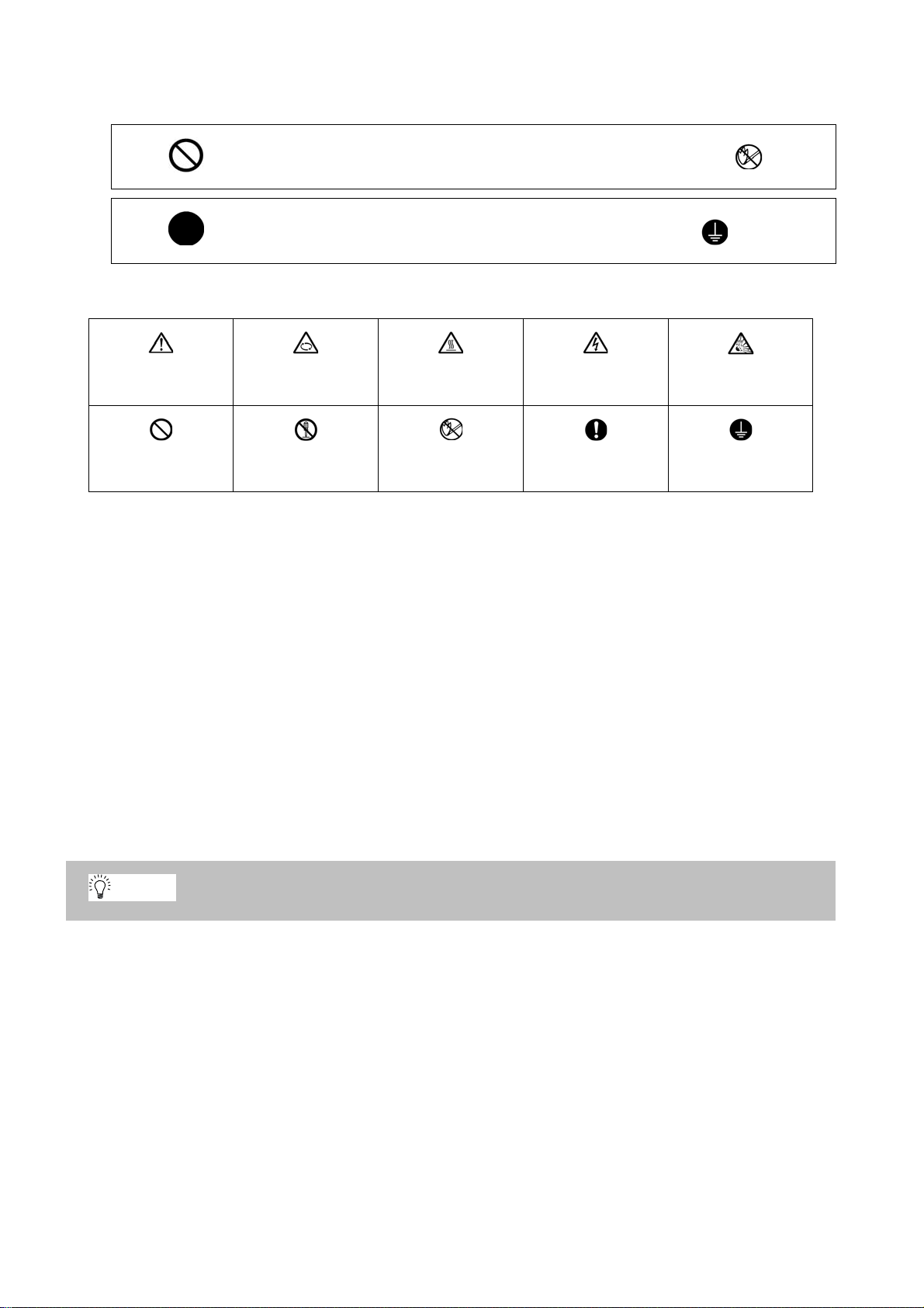
The signs indicating prohibited and mandatory matters are explained below.
POINT
Indicates a prohibited matter. For example, "Fire Prohibited" is indicated as .
Indicates a mandatory matter. For example, grounding is indicated as .
The meaning of each pictorial sign is as follows.
CAUTION
Prohibited
CAUTION rotated
Disassembly is
prohibited
object
CAUTION HOT Danger Electric shock
KEEP FIRE AWAY General instruction
Danger explosive
risk
Earth ground
After reading this specifications and instructions manual, store it where the user can access it easily for
reference.
The numeric control unit is configured of the control unit, operation board, servo drive unit, spindle drive
unit, power supply, servomotor and spindle motor, etc.
In this section "Precautions for safety", the following items are generically called the "motor".
• Servomotor
• Linear servomotor
• Spindle motor
In this section "Precautions for safety", the following items are generically called the "unit".
• Servo drive unit
• Spindle drive unit
• Power supply unit
• Scale interface unit
• Magnetic pole detection unit
Important matters that should be understood for operation of this machine are indicated as a POINT
in this manual.
Page 8

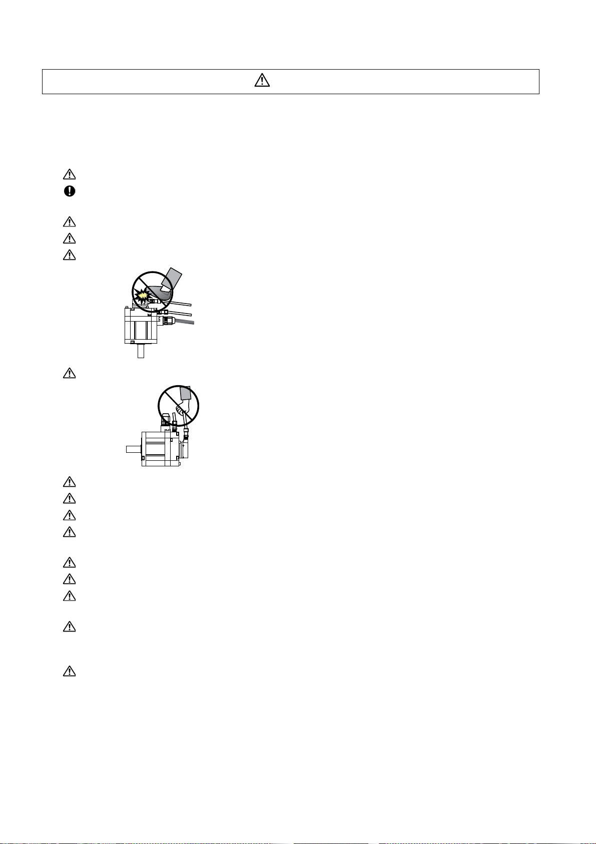
1. Electric shock prevention
Do not open the front cover while the power is ON or during operation . Failure to observe this could lead
to electric shocks.
Do not operate the unit with the front cover removed. The high voltage terminals and charged sections
will be exposed, and can cause electric shocks.
Do not remove the front cover and connector even when the power is OFF unless carrying out wiring
work or periodic inspections. The inside of the units is charged, and can cause electric shocks.
Since the high voltage is supplied to the main circuit connector while the power is ON or during
operation, do not touch the main circuit connector with an adjustment screwdriver or the pen tip. Fa ilure
to observe this could lead to electric shocks.
Wait at least 15 minutes after turning the power OFF, confirm that the CHARGE lamp has gone out, and
check the voltage between P and N terminals with a tester, etc., before starting wiring, maintenance or
inspections. Failure to observe this could lead to electric shocks.
Ground the unit and motor. For the motor, ground it via the drive unit.
Wiring, maintenance and inspection work must be done by a qualified technician.
Wire the servo drive unit and servomotor after installation. Failure to observe this could lead to electric
shocks.
Do not touch the switches with wet hands. Failure to observe this could lead to electric shocks.
Do not damage, apply forcible stress, place heavy items on the cables or get them caught. Failure to
observe this could lead to electric shocks.
After assembling the built-in IPM spindle motor, if the rotor is rotated by hand etc., voltage occurs
between the terminals of lead. Take care not to get electric shocks.
WARNING
Page 9

2. Injury prevention
When handling a motor, perform operations in safe clothing.
In the system where the optical communication with CNC is executed, do not see directly the light
generated from CN1A/CN1B connector of drive unit or the end of cable. When the light gets into eye,
you may feel something is wrong for eye.
(The light source of optical communication corresponds to class1 defined in JISC6802 or IEC60825-1.)
The linear servomotor, direct-drive motor and built-in IPM spindl e motor uses permanent ma gnets in the
rotor, so observe the following precautions .
(1)Handling
• The linear servomotor, direct-drive motor and built-in IPM spindle motor could adversely affect
medical electronics such as pacemakers, etc., therefore, do not approach the rotor.
• Do not place magnetic materials as iron.
• When a magnetic material as iron is placed, take safety measure not to pinch finger s or hands
due to the magnetic attraction force.
• Remove metal items such as watch, piercing jewelry, necklace, etc.
• Do not place portable items that could malfunction or fail due to the influence of the magnetic
force.
• When the rotor is not securely fixed to the machine or device, do not leave it unattended but store
it in the package properly.
(2)Transportation and storage
• Correctly store the rotor in the package to transport and store.
• During transportation and storage, draw people's attention by applying a notice saying "Strong
magnet-Handle with care" to the package or storage shelf.
• Do not use a damaged package.
(3)Installation
• Take special care not to pinch fingers, etc., when installing (and unpacking) the linear servomotor.
Page 10

1. Fire prevention
CAUTION
Install the units, motors and regenerative resistor on non-combustible material. Direct installation on
combustible material or near combustible materials could lead to fires.
Always install a circuit protector and contactor on the servo drive unit power input as explained in this
manual. Refer to this manual and select the correct circuit protector and contactor. An incorrect
selection could result in fire.
Shut off the power on the unit side if a fault occurs in the units. Fires could be caused if a large current
continues to flow.
When using a regenerative resistor, provide a sequence that shuts off the power with the regenerative
resistor's error signal. The regenerative resistor could abnormally overheat and cause a fire due to a
fault in the regenerative transistor, etc.
The battery unit could heat up, ignite or rupture if submerged in water, or if the poles are incorrectly
wired.
Cut off the main circuit power with the contactor when an alarm or emergency stop occurs.
2. Injury prevention
Do not apply a voltage other than that specified in this manual, on each terminal. Failure to observe this
item could lead to ruptures or damage, etc.
Do not mistake the terminal connections. Failure to observe this item could lead to ruptures or damage,
etc.
Do not mistake the polarity (+,- ). Failure to observe this item could lead to ruptures or damage, etc.
Do not touch the radiation fin on unit back face, regenerative resistor or motor, etc., or place parts
(cables, etc.) while the power is turned ON or immediately after turning the power OFF. These parts
may reach high temperatures, and can caus e bu rn s or part dam a ge .
Structure the cooling fan on the unit back face, etc., etc so that it cannot be touched afte r installation.
Touching the cooling fan during operation could lead to injuries.
Take care not to suck hair, clothes, etc. into the cooling fan.
Page 11
3. Various precautions
CAUTION
Observe the following precautions. Incorrect handling of the unit could lead to faults, injuries and electric
shocks, etc.
(1) Transportation and installation
Correctly transport the product according to its weight.
Use the motor's hanging bolts only when transporting the motor. Do not transport the machine when the
motor is installed on the machine.
Do not stack the products above the tolerable number.
Follow this manual and install the unit or motor in a place where the weight can be borne.
Do not get on top of or place heavy objects on the unit.
Do not hold the cables, axis or detector when transporting the motor.
Do not hold the connected wires or cables when transporting the units.
Do not hold the front cover when transporting the unit. The unit could drop.
Always observe the installation directions of the units or motors.
Secure the specified distance between the units and control panel, or between the servo drive unit and
other devices.
Do not install or run a unit or motor that is damaged or missing parts.
Do not block the intake or exhaust ports of the motor provided with a cooling fan.
Do not let foreign objects enter the units or motors. In particular, if conductive objects such as screws or
metal chips, etc., or combustible materials such as oil enter, rupture or breakage could occur.
Provide adequate protection using a material such as connector for conduit to prevent screws, metallic
detritus, water and other conductive matter or oil and other combustible matter from entering the motor
through the power line lead-out port.
The units, motors and detectors are precision devices, so do not drop them or apply strong impacts to
them.
Page 12
CAUTION
Store and use the units under the following environment conditions.
Environment Unit Motor
Operation: 0 to 55°C(with no freezing),
Ambient temperature
Ambient humidity
Atmosphere
Altitude
Vibration/impact According to each unit or motor specification
Storage / Transportation: -15°C to 70°C
(with no freezing)
Operation: 90%RH or less
(with no dew condensation)
Storage / Transportation: 90%RH or less
(with no dew condensation)
Indoors (no direct sunlight)
With no corrosive gas, inflammable gas, oil mist, dust or conductive fine particles
Operation/Storage: 1000 meters or less above sea
level,
Transportation: 13000 meters or less above sea
level
(Note 1) For details, confirm each unit or motor specifications in addition.
(Note 2) -15°C to 55°C for linear servomotor.
Securely fix the servomotor to the machine. Insufficient fixing could lead to the servomotor slipping off
during operation.
Always install the servomotor with reduction gear in the designated direction. Failure to do so could lead
to oil leaks.
Structure the rotary sections of the motor so that it can never be touched during operation. Install a
cover, etc., on the shaft.
When installing a coupling to a servomotor shaft end, do not apply an impact by hammering, etc. The
detector could be damaged.
Do not apply a load exceeding the tolerable load onto the servomotor shaft. The shaft could break.
Store the motor in the package box.
When inserting the shaft into the built-in IPM spindle mo tor, do not heat the rotor highe r than 130°C. The
magnet could be demagnetized, and the specifications characteristics will not be ensured.
Always use a nonmagnetic tool (explosion-proof beryllium copper alloy safety tool: NGK Insulators, etc.)
when installing the linear servomotor.
Always provide a mechanical stopper on the end of the linear servomotor's travel path.
If the unit has been stored for a long time, always check the operation before starting actual operation.
Please contact the Service Center, Service Station, Sales Office or delayer.
Operation: 0 to 40°C(with no freezing),
Storage: -15°C to 70°C (Note2) (with no freezing)
Operation: 80%RH or less
(with no dew condensation),
Storage: 90%RH or less
(with no dew condensation)
Operation: 1000 meters or less above sea level,
Storage: 10000 meters or less above sea level
(2) Wiring
Correctly and securely perform the wiring. Failure to do so could lead to abnormal operation of the
motor.
Do not install a condensing capacitor, surge absorber or radio noise filter on the output sid e of the drive
unit.
Correctly connect the output side of the drive unit (terminals U, V, W). Failure to do so could lead to
abnormal operation of the motor.
When using a power regenerative power supply unit, always install an AC reactor for each power supply
unit.
In the main circuit power supply side of the unit, always install an appropriate circuit protector or
contactor for each unit. Circuit protector or contactor cannot be shared by several units.
Page 13
CAUTION
RA
)
COM
(24VDC)
RA
Servodrive unit
Servodrive unit
Control output
signal
Control output
signal
Always connect the motor to the drive unit's output terminals (U, V, W).
Do not directly connect a commercial power supply to the servomotor. Failure to observe this could
result in a fault.
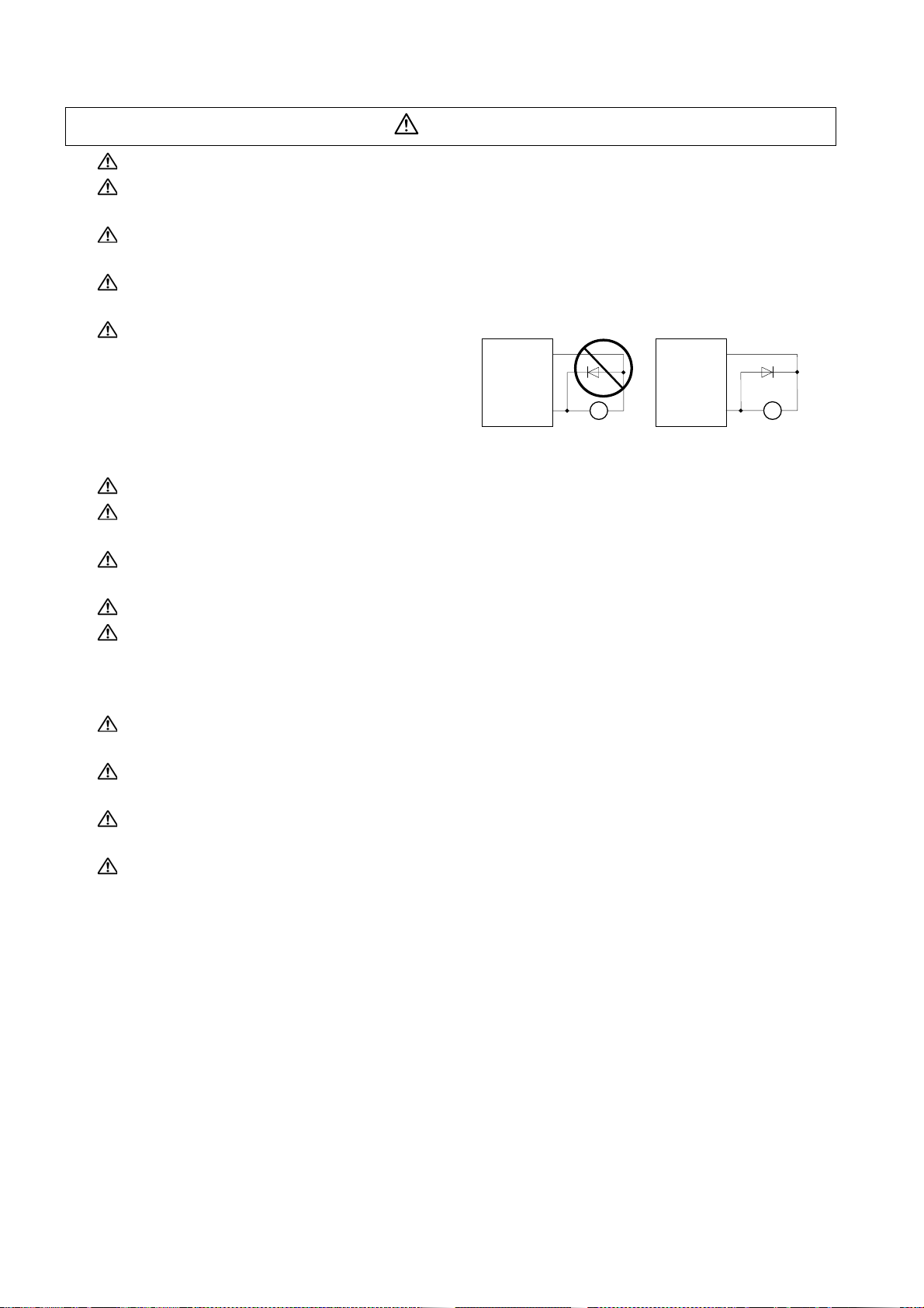
When using an inductive load such as a relay, always connect a diode as a noise measure parallel to
the load.
When using a capacitance load such as a lamp, always connect a protective resistor as a noise
measure serial to the load.
Do not reverse the direction of a diode which
connect to a DC relay for the control output
signals such as contractor and motor brake
output, etc. to suppress a surge. Connecting it
backwards could cause the drive unit to
malfunction so that signals are not output, and
emergency stop and other safety circuits are inoperable.
Do not connect/disconnect the cables connected between the units while the power is ON.
Securely tighten the cable connector fixing screw or fixing mechanism. An insecure fixing could cause
the cable to fall off while the power is ON.
When using a shielded cable instructed in the instruction manual, always ground the cable with a cable
clamp, etc.
Always separate the signals wires from the drive wire and power line.
Use wires and cables that have a wire diameter, heat resistance and flexibility that conforms to the
system.
COM
(24VDC
(3) Trial operation and adjustment
Check and adjust each program and parameter before starting op er ation . Failur e to do so cou l d lead to
unforeseen operation of the machine.
Do not make remarkable adjustments and changes of parameter as the operation could become
unstable.
The usable motor and unit combination is predetermined. Always check the combinations and
parameters before starting trial operation.
The linear servomotor does not have a stopping device such as magnetic brakes. Install a stopping
device on the machine side.
Page 14
(4) Usage methods
CAUTION
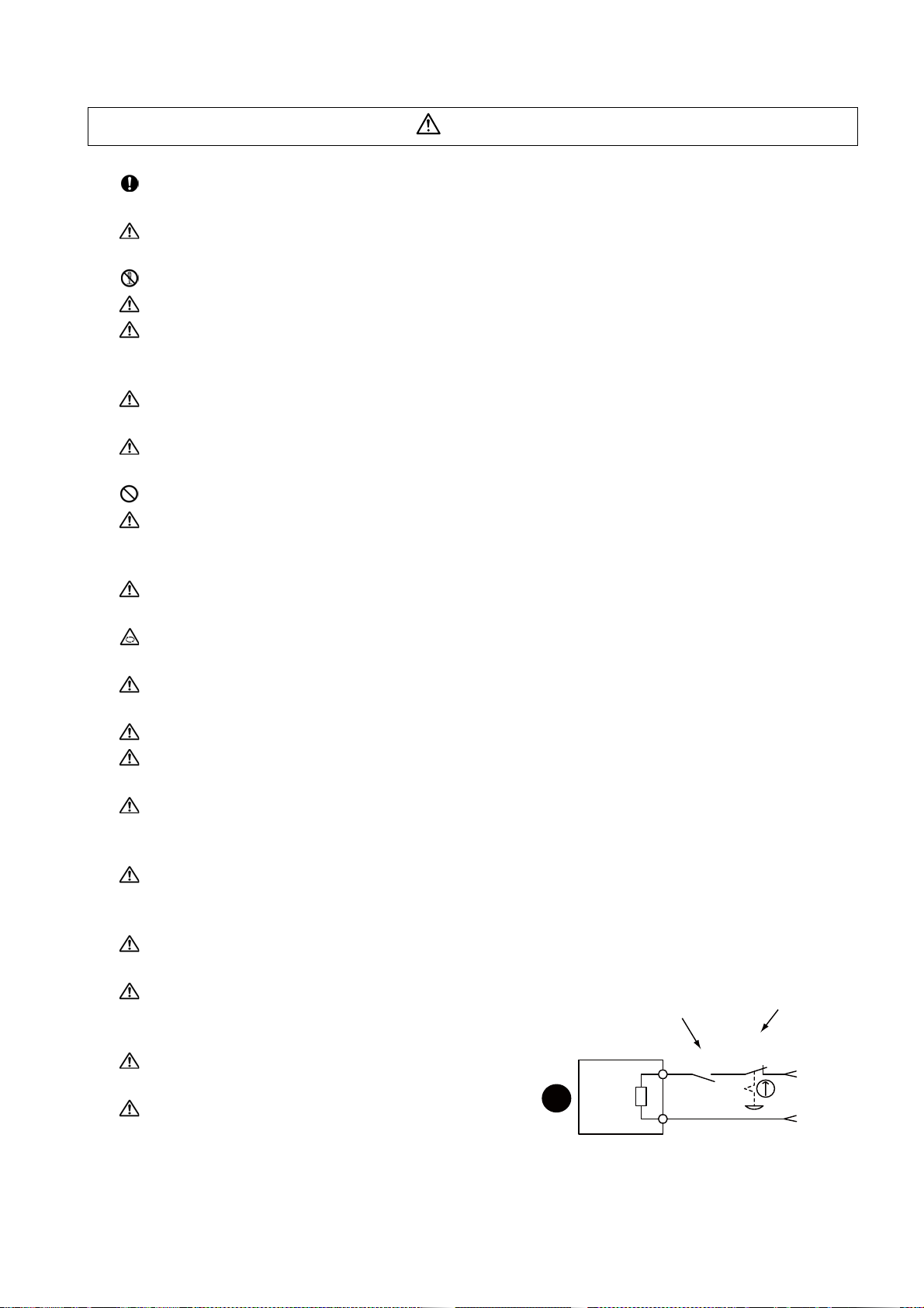
In abnormal state, install an external emergency stop circuit so that the operation can be stopped and
power shut off immediately.
Turn the power OFF immediately if smoke, ab nor ma l noise or odors are generated from the unit or
motor.
Do not disassemble or repair this product.
Never make modifications.
When an alarm occurs, the machine will start suddenly if an alarm reset (RST) is carried out while an
operation start signal (ST) is being input. Always confirm that the operation signal is OFF before
carrying out an alarm reset. Failure to do so could lead to accidents or injuries.
Reduce magnetic damage by installing a noise filter. The electronic devices used near the unit could be
affected by magnetic noise. Install a line noise filter, etc., if there is a risk of magnetic noise.
Use the unit, motor and regenerative resistor with the designated combinatio n. Failur e to do so could
lead to fires or trouble.
The brake (magnetic brake) of the servomotor are for ho ldin g, and m ust not b e used fo r nor mal br aking .
There may be cases when holding is not possible due to the magnetic brake's life, the machine
construction (when ball screw and servomotor are coupled via a timing belt, etc.) or the magnetic
brake's failure. Install a stop device to ensure safety on the machine side.
After changing the programs/parameters or after maintenance an d inspection, always test the operation
before starting actual operation.
Do not enter the movable range of the machine during automatic operation. Never place body parts
near or touch the spindle during rotation.
Follow the power supply specification conditions given in each specification for the power (input voltage,
input frequency, tolerable sudden power failure time, etc.).
Set all bits to "0" if they are indicated as not used or empty in the explanation on the bits.
Do not use the dynamic brakes except during the emergency stop. Continued use of the dynamic
brakes could result in brake damage.
If a circuit protector for the main circuit power supply is shared by several units, the circuit protector may
not activate when a short-circuit fault occurs in a small capacity unit. This is dangerous, so never share
the circuit protector.
Mitsubishi spindle motor is dedicated to machine tools. Do not use for other purposes.
(5) Troubleshooting
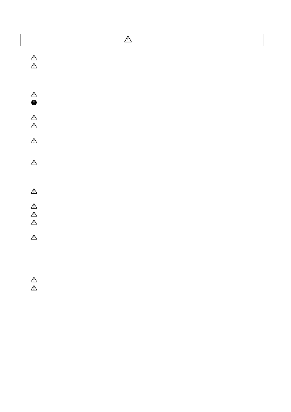
If a hazardous situation is predicted during power failure or product trouble , use a servomotor with
magnetic brakes or install an external brake mechanism.
Use a double circuit configuration that allows the
operation circuit for the magnetic brakes to be opera ted
even by the external emergency stop signal.
Always turn the main circuit power of the motor OFF
when an alarm occurs.
If an alarm occurs, remove the cause, and secure the
Shut off with the servomotor
brake control output.
Servomotor
Magnetic
brake
MBR
Shut off with NC brake
control PLC output.
safety before resetting the alarm.
EMG
24VDC
Page 15
CAUTION
(6) Maintenance, inspection and part replacement
Always backup the programs and parameters be fo re star tin g ma in te na nc e or insp ect ion s.
The capacity of the electrolytic capacitor will drop over time due to self-discharging, etc. To prevent
secondary disasters due to failures, replacing this part every five years when used under a normal
environment is recommended. Contact the Service Center, Service Station, Sales Office or delayer for
repairs or part replacement.
Do not perform a megger test (insulation resistance measurement) during inspections.
If the battery low warning is issued, back up the machining programs, tool data and parameters with an
input/output unit, and then rep l ac e th e ba ttery.
Do not short circuit, charge, overheat, incinerate or disassemble the battery.
For after-purchase servicing of the built-in motor (including the detector), supplies of servicing parts and
repairs can only be offered.
For maintenance, part replacement, and services in case of failures in the built-in motor (including the
detector), take necessary actions at your end. For spindle drive unit, Mitsubishi can offer the afterpurchase servicing as with the general spindle drive unit.
When a failure has occurred in the built-in motor (including the detector), some period of time can be
required to supply the servicing parts or repair. Prepare the spare parts a t your end whenever possible.
(7) Disposal
Take the batteries and backlights for LCD, etc., off from the controller, drive unit an d motor, and dispose
of them as general industrial wastes.
Do not disassemble the unit or motor.
Dispose of the battery according to local laws.
Always return the secondary side (magnet side) of the linear servomotor to the Service Center or
Service Station.
When incinerating optical communication cable, hydrogen fluoride gas or hydrogen chloride gas which
is corrosive and harmful may be generated. For disposal of optical communication cable, request for
specialized industrial waste disposal services that has incineration facility for disposing hydrogen
fluoride gas or hydrogen chloride gas.
(8) Transportation
The unit and motor are precision parts and must be handled carefully.
According to a United Nations Advisory, the battery unit and battery must be transported according to
the rules set forth by the International Civil Aviation Organization (ICAO), International Air
Transportation Association (IATA), International Maritime Organization (IMO), and United States
Department of Transportation (DOT), etc.
(9) General precautions
The drawings given in this manual show the covers and safety partitions, etc., removed to provide a
clearer explanation. Always return the covers or partitions to their respective places before starting
operation, and always follow the instructions given in this manual.
Page 16

Treatment of waste
The following two laws will apply when disposing of this product. Considerations must be made to each law.
The following laws are in effect in Japan. Thus, when using this product overseas, the local laws will have a
priority. If necessary, indicate or notify these laws to the final user of the product.
(1) Requirements for "Law for Promotion of Effective Utilization of Resources"
(a) Recycle as much of this product as possible when finished with use.
(b) When recycling, often parts are sorted into steel scraps and electric parts, etc., and sold to scrap
contractors. Mitsubishi recommends sorting the product and selling the members to appropriate
contractors.
(2) Requirements for "Law for Treatment of Waste and Cleaning"
(a) Mitsubishi recommends recycling and selling the product when no longer nee ded according to item
(1) above. The user should make an effort to reduce waste in this manner.
(b) When disposing a product that cannot be resold, it shall be treated as a waste product.
(c) The treatment of industrial waste must be commissioned to a licensed industrial waste treatment
contractor, and appropriate measures, including a manifest control, must be taken.
(d) Batteries correspond to "primary batteries", and must be disposed of according to local disposal
laws.
Page 17

Page 18

Disposal
(Note) This symbol mark is for EU countries only.
This symbol mark is according to the directive 2006/66/EC Article 20 Information for endusers and Annex II.
Your MITSUBISHI ELECTRIC product is designed and manufactured with high quality materials and
components which can be recycled and/or reused.
This symbol means that batteries and accumulators, at their end-of-life, should be disposed of
separately from your household waste.
If a chemical symbol is printed beneath the symbol shown above, this chemical symbol means that the
battery or accumulator contains a heavy metal at a certain concentration. This will be indicated as
follows:
Hg: mercury (0,0005%), Cd: cadmium (0,002%), Pb: lead (0,004%)
In the European Union there are separate collection systems for used batteries and accumulators.
Please, dispose of batteries and accumulators correctly at your local community waste collection/
recycling centre.
Please, help us to conserve the environment we live in!
Page 19

Page 20

本製品の取扱いについて
( 日本語 /Japanese)
本製品は工業用 ( クラス A) 電磁環境適合機器です。販売者あるいは使用者はこの点に注意し、住商業環境以外で
の使用をお願いいたします。
Handling of our product
(English)
This is a class A product. In a domestic environment this product may cause radio interference in which case the
user may be required to take adequate measures.
본 제품의 취급에 대해서
( 한국어 /Korean)
이 기기는 업무용 (A 급 ) 전자파적합기기로서 판매자 또는 사용자는 이 점을 주의하시기 바라며 가정외의 지역에
서 사용하는 것을 목적으로 합니다 .
Page 21

Page 22

Contents
1 Introduction................................................................1 - 1
1-1 Servo/spindle drive system configuration .........................................................................................1 - 2
1-1-1 System configuration............. ... ... .... ... .......................................... ... ......................................... 1 - 2
1-2 Explanation of type ...........................................................................................................................1 - 3
1-2-1 Servomotor type.................................................... ... .... ... ... ... .... ............................................... 1 - 3
1-2-2 Servo drive unit type.... ... .......................................... .... ... .......................................... ............... 1 - 5
1-2-3 Spindle motor type.................................................................................................................... 1 - 7
1-2-4 Tool spindle motor type...................................................... ... .... ... ... ... ... ................................... 1 - 9
1-2-5 Spindle drive unit type............................................................................................................1 - 11
1-2-6 Power supply unit type .......................... ... ... .... ... ... ... .......................................... .... ................1 - 12
1-2-7 AC reactor type................................... ... ... ... .... ... ... ... .......................................... .... ................1 - 13
2 Specifications.............................................................2 - 1
2-1 Servomotor.......................................................................................................................................2 - 2
2-1-1 Specifications list................... ... ... .......................................... .... ... ............................................ 2 - 2
2-1-2 Torque characteristics.................................................. .......................................... ... ... .......... 2 - 12
2-2 Spindle motor..................................................................................................................................2 - 19
2-2-1 Specifications ........................ ... ... .... .......................................... ... ... ....................................... 2 - 19
2-2-2 Output characteristics.................................. .... ... ... ... .......................................... .... ................2 - 35
2-3 Tool spindle motor.......................................................................................................................... 2 - 44
2-3-1 Specifications ........................ ... ... .... .......................................... ... ... ....................................... 2 - 44
2-3-2 Output characteristics.................................. .... ... ... ... .......................................... .... ................2 - 48
2-4 Drive unit.........................................................................................................................................2 - 50
2-4-1 Installation environment conditions ........................................................................................ 2 - 50
2-4-2 Servo drive unit...................................... .......................................... ... .................................... 2 - 51
2-4-3 Spindle drive unit....................................................................................................................2 - 53
2-4-4 Power supply unit ........................................................... ... ... .... ............................................. 2 - 55
2-4-5 Unit outline dimension drawing........................................ ... ... .... ... ... ... ... .... ... ... ....... ... ... ... .......2 - 56
2-4-6 AC reactor .......................... ... ... ... .......................................... .... ... .......................................... 2 - 57
2-4-7 Explanation of each part.........................................................................................................2 - 60
3 Function Specifications.............................................3 - 1
Function specifications list...................................................................................................................... 3 - 2
3-1 Base control functions ...................................................................................................................... 3 - 5
3-1-1 Full closed loop control....... ... ... ... .... ... ... ... .......................................... ... ................................... 3 - 5
3-1-2 Position command synchronous control...................................................................................3 - 5
3-1-3 Speed command synchronous control..................................................................................... 3 - 6
3-1-4 Distance-coded reference position control...............................................................................3 - 6
3-1-5 Spindle's continuous position loop control................................................................................3 - 7
3-1-6 Coil changeover control............................................................................................................ 3 - 7
3-1-7 Gear changeover control................. ... ... ... ... .......................................... .... ............................... 3 - 7
3-1-8 Orientation control.............................................. ... ... .... ... ... ... ................................................... 3 - 7
3-1-9 Indexing control............................................... ... ... ... .......................................... .... ..................3 - 7
3-1-10 Synchronous tapping control.................................................................................................. 3 - 7
3-1-11 Spindle synchronous control .................................................................................................. 3 - 8
3-1-12 Spindle/C axis control............................................................................................................. 3 - 8
3-1-13 Proximity switch orientation control........................................................................................3 - 8
3-1-14 Power regeneration control .................................................................................................... 3 - 8
3-1-15 Resistor regeneration control ................................................................................................. 3 - 8
3-2 Servo/Spindle control functions ........................................................................................................3 - 9
3-2-1 Torque limit function.................................................................................................................3 - 9
Page 23

3-2-2 Variable speed loop gain control ..............................................................................................3 - 9
3-2-3 Gain changeover for synchronous tapping control...................................................................3 - 9
3-2-4 Speed loop PID changeover control.......................................................................................3 - 10
3-2-5 Disturbance torque observer ..................................................................................................3 - 10
3-2-6 Smooth High Gain control (SHG control) ...............................................................................3 - 10
3-2-7 High-speed synchronous tapping control (OMR-DD control) .................................................3 - 10
3-2-8 Dual feedback control.............................................................................................................3 - 11
3-2-9 HAS control ............................................................................................................................3 - 11
3-2-10 Control loop gain changeover...............................................................................................3 - 11
3-2-11 Spindle output stabilizing control..........................................................................................3 - 12
3-2-12 High-response spindle acceleration/deceleration function ...................................................3 - 12
3-3 Compensation control function .......................................................................................................3 - 13
3-3-1 Jitter compensation ................................................................................................................3 - 13
3-3-2 Notch filter ..............................................................................................................................3 - 13
3-3-3 Adaptive tracking-type notch filter ..........................................................................................3 - 13
3-3-4 Overshooting compensation...................................................................................................3 - 14
3-3-5 Machine end compensation control........................................................................................3 - 14
3-3-6 Lost motion compensation type 2...........................................................................................3 - 15
3-3-7 Lost motion compensation type 3...........................................................................................3 - 15
3-3-8 Lost motion compensation type 4...........................................................................................3 - 16
3-3-9 Spindle motor temperature compensation function................................................................3 - 16
3-4 Protection function..........................................................................................................................3 - 17
3-4-1 Deceleration control at emergency stop.................................................................................3 - 17
3-4-2 Vertical axis drop prevention/pull-up control...........................................................................3 - 17
3-4-3 Earth fault detection................................................................................................................3 - 17
3-4-4 Collision detection function.....................................................................................................3 - 18
3-4-5 Safety observation function....................................................................................................3 - 18
3-4-6 Fan stop detection..................................................................................................................3 - 18
3-4-7 Open-phase detection ............................................................................................................3 - 18
3-4-8 Contactor weld detection........................................................................................................3 - 18
3-5 Sequence functions ........................................................................................................................3 - 19
3-5-1 Contactor control function.......................................................................................................3 - 19
3-5-2 Motor brake control function...................................................................................................3 - 19
3-5-3 External emergency stop function ..........................................................................................3 - 19
3-5-4 Specified speed output...........................................................................................................3 - 19
3-5-5 Quick READY ON sequence..................................................................................................3 - 19
3-6 Diagnosis function...........................................................................................................................3 - 20
3-6-1 Monitor output function...........................................................................................................3 - 20
3-6-2 Machine resonance frequency display function......................................................................3 - 27
3-6-3 Machine inertia display function .............................................................................................3 - 27
3-6-4 Motor temperature display function........................................................................................3 - 27
3-6-5 Load monitor output function..................................................................................................3 - 27
3-6-6 Open loop control function...................................................................................................... 3 - 27
3-6-7 Power supply voltage display function....................................................................................3 - 27
4 Characteristics........................................................... 4 - 1
4-1 Servomotor .......................................................................................................................................4 - 2
4-1-1 Environmental conditions ........................................................................................................4 - 2
4-1-2 Quakeproof level ......................................................................................................................4 - 2
4-1-3 Shaft characteristics ................................................................................................................. 4 - 3
4-1-4 Machine accuracy.....................................................................................................................4 - 4
4-1-5 Oil / water standards.................................................................................................................4 - 5
4-1-6 Installation of servo motor ........................................................................................................4 - 6
4-1-7 Overload protection characteristics..........................................................................................4 - 6
4-1-8 Magnetic brake.......................................................................................................................4 - 14
4-1-9 Dynamic brake characteristics ...............................................................................................4 - 19
4-2 Spindle motor..................................................................................................................................4 - 22
4-2-1 Environmental conditions ......................................................................................................4 - 22
4-2-2 Shaft characteristics ...............................................................................................................4 - 22
Page 24

4-2-3 Machine accuracy................................................................................................................... 4 - 23
4-2-4 Installation of spindle motor....................................................................................................4 - 23
4-3 Tool spindle motor.......................................................................................................................... 4 - 24
4-3-1 Environmental conditions ............................... ... ... ... .... ... ... ... .... ... ... ... ... ....... ... ... .... ... ... ... .......4 - 24
4-3-2 Shaft characteristics.............................................. ... .... ... ... ... .... ............................................. 4 - 24
4-3-3 Tool spindle temperature characteristics................................................................................ 4 - 25
4-4 Drive unit.........................................................................................................................................4 - 26
4-4-1 Environmental conditions ............................... ... ... ... .... ... ... ... .... ... ... ... ... ....... ... ... .... ... ... ... .......4 - 26
4-4-2 Heating value................................... .......................................... ... .......................................... 4 - 27
4-4-3 Drive unit arrangement...........................................................................................................4 - 28
5 Dedicated Options .....................................................5 - 1
5-1 Servo options....................................................................................................................................5 - 2
5-1-1 Dynamic brake unit (MDS-D-DBU)........................................................................................... 5 - 7
5-1-2 Battery option (ER6V-C119B, A6BAT, MDS-A-BT, MDS-BTBOX-36).....................................5 - 9
5-1-3 Ball screw side detector (OSA105-ET2, OSA166-ET2N)....................................................... 5 - 20
5-1-4 Machine side detector ............................................................................................................5 - 22
5-2 Spindle options............................................................................................................................... 5 - 26
5-2-1 Spindle side ABZ pulse output detector (OSE-1024 Series).................................................. 5 - 27
5-2-2 Spindle side PLG serial output detector (TS5690, MU1606 Series) ...................................... 5 - 29
5-2-3 Spindle side accuracy serial output detector (ERM280, MPCI Series) .................................. 5 - 33
5-3 Detector interface unit.....................................................................................................................5 - 34
5-3-1 Serial output interface unit for ABZ analog detector MDS-B-HR............................................5 - 34
5-3-2 Serial signal division unit MDS-B-SD ..................................................................................... 5 - 36
5-3-3 Pulse output interface unit for ABZ analog detector IBV Series
(Other manufacturer's product) ..............................................................................5 - 38
5-3-4 Serial output interface unit for ABZ analog detector EIB192M
(Other manufacturer's product) ..............................................................................5 - 39
5-3-5 Serial output interface unit for ABZ analog detector EIB392M
(Other manufacturer's product) ..............................................................................5 - 40
5-3-6 Serial output interface unit for ABZ analog detector ADB-20J Series
(Other manufacturer's product) ..............................................................................5 - 41
5-4 Drive unit option.............................................................................................................................. 5 - 42
5-4-1 Optical communication repeater unit (FCU7-EX022).............................................................5 - 42
5-4-2 DC connection bar.................................................................................................................. 5 - 45
5-4-3 Side protection cover.......... ... .......................................... ... ... ................................................. 5 - 46
5-5 Cables and connectors.................................................................. .... ... ... ....................................... 5 - 48
5-5-1 Cable connection diagram.................................. ... ... .... ... .......................................... ... ..........5 - 48
5-5-2 List of cables and connectors................... ... .......................................... .... .............................5 - 49
5-5-3 Optical communication cable specifications...........................................................................5 - 57
6 Specifications of Peripheral Devices.......................6 - 1
6-1 Selection of wire ...............................................................................................................................6 - 2
6-1-1 Example of wires by unit.............................. .......................................... .... ...............................6 - 2
6-2 Selection of circuit protector and contactor.......................................................................................6 - 8
6-2-1 Selection of circuit protector..................................................................................................... 6 - 8
6-2-2 Selection of contactor...............................................................................................................6 - 9
6-3 Selection of earth leakage breaker................................................................................................. 6 - 10
6-4 Branch-circuit protection (for control power supply) ....................................................................... 6 - 11
6-4-1 Circuit protector.................................................. ... ... .... ... ... ... ................................................. 6 - 11
6-4-2 Fuse protection............ ... .......................................... .... ... ....................................................... 6 - 11
6-5 Noise filter.......................................................................................................................................6 - 12
6-6 Surge absorber...............................................................................................................................6 - 13
6-7 Relay............................................................................................................................................... 6 - 14
Page 25

7 Selection..................................................................... 7 - 1
7-1 Selection of the servomotor..............................................................................................................7 - 2
7-1-1 Outline ......................................................................................................................................7 - 2
7-1-2 Selection of servomotor capacity..............................................................................................7 - 3
7-1-3 Motor shaft conversion load torque ........................................................................................7 - 11
7-1-4 Expressions for load inertia calculation ..................................................................................7 - 12
7-2 Selection of the spindle motor.........................................................................................................7 - 13
7-3 Selection of the power supply unit..................................................................................................7 - 14
7-3-1 Calculation of spindle output ..................................................................................................7 - 14
7-3-2 Calculation of servo motor output...........................................................................................7 - 16
7-3-3 Selection of the power supply unit..........................................................................................7 - 17
7-3-4 Required capacity of power supply.........................................................................................7 - 19
7-3-5 Example for power supply unit and power supply facility capacity.........................................7 - 20
Appendix 1 Cable and Connector Specifications
...................................................Appendix 1 - 1
Appendix 1-1 Selection of cable..............................................................................................Appendix 1 - 2
Appendix 1-1-1 Cable wire and assembly ......................................................................... Appendix 1 - 2
Appendix 1-2 Cable connection diagram................................................................................Appendix 1 - 4
Appendix 1-2-1 Battery cable............................................................................................. Appendix 1 - 4
Appendix 1-2-2 Power supply communication cable and connector ................................. Appendix 1 - 5
Appendix 1-2-3 Optical communication repeater unit cable .............................................. Appendix 1 - 6
Appendix 1-2-4 Servo / tool spindle detector cable ...........................................................Appendix 1 - 7
Appendix 1-2-5 Brake connector (Brake connector for motor brake control output)........Appendix 1 - 13
Appendix 1-2-6 Spindle detector cable............................................................................ Appendix 1 - 14
Appendix 1-3 Main circuit cable connection diagram............................................................Appendix 1 - 16
Appendix 1-4 Connector outline dimension drawings...........................................................Appendix 1 - 17
Appendix 1-4-1 Connector for drive unit.......................................................................... Appendix 1 - 17
Appendix 1-4-2 Connector for servo and tool spindle......................................................Appendix 1 - 21
Appendix 1-4-3 Connector for spindle .............................................................................Appendix 1 - 25
Appendix 2 Restrictions for Lithium Batteries
...................................................Appendix 2 - 1
Appendix 2-1 Restriction for Packing......................................................................................Appendix 2 - 2
Appendix 2-1-1 Target Products........................................................................................Appendix 2 - 2
Appendix 2-1-2 Handling by User......................................................................................Appendix 2 - 3
Appendix 2-1-3 Reference.................................................................................................Appendix 2 - 4
Appendix 2-2 Products information data sheet (ER battery)...................................................Appendix 2 - 5
Appendix 2-3 Issuing Domestic Law of the United States for Primary Lithium Battery
Transportation ..................................................................................................Appendix 2 - 7
Appendix 2-3-1 Outline of Regulation................................................................................Appendix 2 - 7
Appendix 2-3-2 Target Products........................................................................................Appendix 2 - 7
Appendix 2-3-3 Handling by User......................................................................................Appendix 2 - 7
Appendix 2-3-4 Reference.................................................................................................Appendix 2 - 7
Appendix 2-4 Restriction related to EU Battery Directive........................................................Appendix 2 - 8
Appendix 2-4-1 Important Notes....... ... ... ... .......................................... .... ..........................Appendix 2 - 8
Appendix 2-4-2 Information for end-user........................................................................... Appendix 2 - 8
Appendix 3 Compliance to EC Directives..Appendix 3 - 1
Appendix 3-1 Compliance to EC Directives............................................................................Appendix 3 - 2
Appendix 3-1-1 European EC Directives ...........................................................................Appendix 3 - 2
Appendix 3-1-2 Cautions for EC Directive compliance......................................................Appendix 3 - 2
Page 26

Appendix 4 EMC Installation Guidelines ...Appendix 4 - 1
Appendix 4-1 Introduction....................................................................................................... Appendix 4 - 2
Appendix 4-2 EMC instructions...............................................................................................Appendix 4 - 2
Appendix 4-3 EMC measures................................................................................................. Appendix 4 - 3
Appendix 4-4 Measures for panel structure............................................................................Appendix 4 - 3
Appendix 4-4-1 Measures for control panel unit................................................................Appendix 4 - 3
Appendix 4-4-2 Measures for door ...................................................................................Appendix 4 - 4
Appendix 4-4-3 Measures for operation board panel........................................................ Appendix 4 - 4
Appendix 4-4-4 Shielding of the power supply input section ............................................. Appendix 4 - 4
Appendix 4-5 Measures for various cables.............................................................................Appendix 4 - 5
Appendix 4-5-1 Measures for wiring in panel.....................................................................Appendix 4 - 5
Appendix 4-5-2 Measures for shield treatment.................................................................. Appendix 4 - 5
Appendix 4-5-3 Servo/spindle motor power cable ............................................................. Appendix 4 - 6
Appendix 4-5-4 Servo/spindle motor feedback cable ........................................................Appendix 4 - 7
Appendix 4-6 EMC countermeasure parts..............................................................................Appendix 4 - 7
Appendix 4-6-1 Shield clamp fitting ................................................................................... Appendix 4 - 7
Appendix 4-6-2 Ferrite core...............................................................................................Appendix 4 - 8
Appendix 4-6-3 Power line filter......................................................................................... Appendix 4 - 8
Appendix 4-6-4 Surge protector............................ .......................................... .... .............Appendix 4 - 15
Appendix 5 EC Declaration of Conformity
...................................................Appendix 5 - 1
Appendix 5-1 Compliance to EC Directives............................................................................ Appendix 5 - 2
Appendix 5-1-1 Low voltage equipment............................................................................. Appendix 5 - 2
Appendix 6 Instruction Manual for Compliance
with UL/c-UL Standard............Appendix 6 - 1
Appendix 6-1 Operation surrounding air ambient temperature............................................... Appendix 6 - 2
Appendix 6-2 Notes for AC servo/spindle system...................................................................Appendix 6 - 2
Appendix 6-2-1 General Precaution................................................................................... Appendix 6 - 2
Appendix 6-2-2 Installation ................................................................................................ Appendix 6 - 2
Appendix 6-2-3 Short-circuit ratings (SCCR)..................................................................... Appendix 6 - 2
Appendix 6-2-4 Peripheral devices.................................................................................... Appendix 6 - 2
Appendix 6-2-5 Field Wiring Reference Table for Input and Output (Power Wiring).........Appendix 6 - 3
Appendix 6-2-6 Motor Over Load Protection ....................................................................Appendix 6 - 6
Appendix 6-2-7 Flange of servo motor............................................................................... Appendix 6 - 6
Appendix 6-2-8 Spindle Drive/Motor Combinations........................................................... Appendix 6 - 7
Appendix 6-2-9 Servo Drive/Motor Combinations..............................................................Appendix 6 - 7
Appendix 6-3 AC Servo/Spindle System Connection ............................................................. Appendix 6 - 8
Appendix 6-3-1 MDS-D/DH/DM-Vx/SP Series................................................................... Appendix 6 - 8
Appendix 6-3-2 MDS-D-SVJ3/SPJ3 Series.......................................................................Appendix 6 - 8
Appendix 7 Compliance with Restrictions in China
...................................................Appendix 7 - 1
Appendix 7-1 Compliance with China CCC certification system.............................................Appendix 7 - 2
Appendix 7-1-1 Outline of China CCC certification system ...............................................Appendix 7 - 2
Appendix 7-1-2 First catalogue of products subject to compulsory pr oduct certification...Appendix 7 - 2
Appendix 7-1-3 Precautions for shipping products ............................................................ Appendix 7 - 3
Appendix 7-1-4 Application for exemption......................................................................... Appendix 7 - 3
Appendix 7-1-5 Mitsubishi NC product subject to/not subject to CCC certification............Appendix 7 - 5
Page 27

Appendix 7-2 Response to the China environment restrictions..............................................Appendix 7 - 6
Appendix 7-2-1 Outline of the law on the pollution prevention and control
for electronic information products ...........................................................Appendix 7 - 6
Appendix 7-2-2 Response to the drive product for Mitsubishi NC .....................................Appendix 7 - 6
Appendix 7-2-3 Indication based on “Pollut ion sup pr essio n ma r king req u es t
for electronic information product”............................................................Appendix 7 - 7
Page 28

Outline for MDS-D/DH Series
Instruction Manual (IB-1500025-H)
1 Installation
1-1 Installation of servomotor
1-1-1 Environmental conditions
1-1-2 Quakeproof level
1-1-3 Cautions for mounting load (prevention of
impact on shaft)
1-1-4 Installation direction
1-1-5 Shaft characteristics
1-1-6 Machine accuracy
1-1-7 Coupling with the load
1-1-8 Oil/water standards
1-1-9 Installation of servomotor
1-1-10 Cable stress
1-2 Installation of spindle motor
1-2-1 Environmental conditions
1-2-2 Cautions for mounting fittings
1-2-3 Shaft characteristics
1-2-4 Machine accuracy
1-2-5 Coupling with the fittings
1-2-6 Ambient environment
1-2-7 Installation of spindle motor
1-2-8 Connection
1-2-9 Cable stress
1-3 Installation of tool spindle motor
1-3-1 Environmental conditions
1-3-2 Shaft characteristics
1-4 Installation of the drive unit
1-4-1 Environmental conditions
1-4-2 Installation direction and clearance
1-4-3 Prevention of entering of foreign matter
1-4-4 Panel installation hole work drawings
(Panel cut drawings)
1-4-5 Heating value
1-4-6 Heat radiation countermeasures
1-5 Installation of the spindle detector
1-5-1 Spindle side ABZ pulse output detector
(OSE-1024 Series)
1-5-2 Spindle side PLG serial output detector
(TS5690, MU1606 Series)
1-5-3 Installation accuracy diagnosis for PLG
detector
1-6 Noise measures
2 Wiring and Connection
2-1 Part system connection diagram
2-2 Main circuit terminal block/control circuit
connector
2-2-1 Names and applications of main circuit
terminal block signals and control
circuit connectors
2-2-2 Connector pin assignment
2-3 NC and drive unit connection
2-4 Connecting with optical communication repeater
unit
2-5 Motor and detector connection
2-5-1 Connection of the servomotor
2-5-2 Connection of the full-closed loop system
2-5-3 Connection of the speed command
synchronization control system
2-5-4 Connection of the spindle motor
2-5-5 Connection of tool spindle motor
2-6 Connection of power supply
2-6-1 Power supply input connection
2-6-2 Connecting the grounding cable
2-7 Wiring of the motor brake
2-7-1 Wiring of the motor magnetic brake
2-7-2 Dynamic brake unit wiring
2-8 Peripheral control wiring
2-8-1 Input/output circuit wiring
2-8-2 Wiring of an external emergency stop
2-8-3 Safety observation function
2-8-4 Specified speed output
2-8-5 Spindle coil changeover
2-8-6 Specifications of proximity switch
3 Setup
3-1 Initial setup
3-1-1 Setting the rotary switch
3-1-2 Setting DIP switch
3-1-3 Transition of LED display after power is
turned ON
3-2 Setting the initial parameters for the servo drive
unit
3-2-1 Setting of servo specification parameters
3-2-2 Setting of machine side detector
3-2-3 Setting of distance-coded reference scale
3-2-4 Setting of speed command synchronous
control
3-2-5 List of standard parameters for each
servomotor
3-2-6 Servo parameters
3-3 Setting the initial parameters for the spindle drive
unit
3-3-1 Setting of parameters related to the spindle
3-3-2 List of standard parameters for each spindle
motor
3-3-3 Spindle specification parameters
3-3-4 Spindle parameters
4 Servo Adjustment
4-1 D/A output specifications for servo drive unit
4-1-1 D/A output specifications
4-1-2 Output data settings
4-1-3 Setting the output magnification
4-2 Servo adjustment procedure
4-3 Gain adjustment
4-3-1 Current loop gain
4-3-2 Speed loop gain
4-3-3 Position loop gain
4-4 Characteristics improvement
4-4-1 Optimal adjustment of cycle time
4-4-2 Vibration suppression measures
4-4-3 Improving the cutting surface precision
4-4-4 Improvement of characteristics during
Page 29

acceleration/deceleration
4-4-5 Improvement of protrusion at quadrant
changeover
4-4-6 Improvement of overshooting
4-4-7 Improvement of the interpolation control
path
4-5 Adjustment during full closed loop control
4-5-1 Outline
4-5-2 Speed loop delay compensation
4-5-3 Dual feedback control
4-6 Settings for emergency stop
4-6-1 Deceleration control
4-6-2 Vertical axis drop prevention control
4-6-3 Vertical axis pull-up control
4-7 Protective functions
4-7-1 Overload detection
4-7-2 Excessive error detection
4-7-3 Collision detection function
4-8 Servo control signal
4-8-1 Servo control input (NC to Servo)
4-8-2 Servo control output (Servo to NC)
5 Spindle Adjustment
5-1 D/A output specifications for spindle drive unit
5-1-1 D/A output specifications
5-1-2 Setting the output data
5-1-3 Setting the output magnification
5-2 Adjustment procedures for each control
5-2-1 Basic adjustments
5-2-2 Gain adjustment
5-2-3 Adjusting the acceleration/deceleration
operation
5-2-4 Orientation adjustment
5-2-5 Synchronous tapping adjustment
5-2-6 High-speed synchronous tapping
5-2-7 Spindle C axis adjustment (For lathe
system)
5-2-8 Spindle synchronization adjustment (For
lathe system)
5-2-9 Deceleration coil changeover valid function
by emergency stop
5-2-10 High-response acceleration/deceleration
function
5-2-11 Spindle cutting withstand level
improvement
5-3 Settings for emergency stop
5-3-1 Deceleration control
5-4 Spindle control signal
5-4-1 Spindle control input (NC to Spindle)
5-4-2 Spindle control output (Spindle to NC)
6 Troubleshooting
6-1 Points of caution and confirmation
6-1-1 LED display when alarm or warning occurs
6-2 Protective functions list of units
6-2-1 List of alarms
6-2-2 List of warnings
6-3 Troubleshooting
6-3-1 Troubleshooting at power ON
6-3-2 Troubleshooting for each alarm No.
6-3-3 Troubleshooting for each warning No.
6-3-4 Parameter numbers during initial parameter
error
6-3-5 Troubleshooting the spindle system when
there is no alarm or warning
7 Maintenance
7-1 Periodic inspections
7-1-1 Inspections
7-1-2 Cleaning of spindle motor
7-2 Service parts
7-3 Adding and replacing units and parts
7-3-1 Replacing the drive unit
7-3-2 Replacing the unit fan
7-3-3 Replacing the battery
7-3-4 Replacing the fuse
Appendix 1 Cable and Connector
Specifications
Appendix 1-1 Selection of cable
Appendix 1-1-1 Cable wire and assembly
Appendix 1-2 Cable connection diagram
Appendix 1-2-1 Battery cable
Appendix 1-2-2 Power supply communication
cable and connector
Appendix 1-2-3 Optical communication repeater
unit cable
Appendix 1-2-4 Servo / tool spindle detector cable
Appendix 1-2-5 Brake connector (Brake
connector for motor brake control
output)
Appendix 1-2-6 Spindle detector cable
Appendix 1-3 Main circuit cable connection diagram
Appendix 1-4 Connector outline dimension drawings
Appendix 1-4-1 Connector for drive unit
Appendix 1-4-2 Connector for servo and tool
spindle
Appendix 1-4-3 Connector for spindle
Appendix 2 Cable and Connector Assembly
Appendix 2-1 CM10-SPxxS-x(D6) plug connector
Appendix 2-2 CM10-APxxS-x(D6) angle plug
connector
Appendix 2-3 CM10-SP-CV reinforcing cover for
straight plug
Appendix 2-4 CM10-AP-D-CV reinforcing cover for
angle plug
Appendix 2-5 1747464-1 plug connector
Appendix 2-5-1 Applicable products
Appendix 2-5-2 Applicable cable
Appendix 2-5-3 Related documents
Appendix 2-5-4 Assembly procedure
Appendix 3 Precautions in Installing
Spindle Motor
Appendix 3-1 Precautions in transporting motor
Page 30

Appendix 3-2 Precautions in selecting motor fittings
Appendix 3-3 Precautions in mounting fittings
Appendix 3-4 Precautions in coupling shafts
Appendix 3-5 Precautions in installing motor in
machine
Appendix 3-6 Other Precautions
Appendix 3-7 Example of unbalance correction
Appendix 3-8 Precautions in balancing of motor with
key
Appendix 4 Compliance to EC Directives
Appendix 4-1 Compliance to EC Directives
Appendix 4-1-1 European EC Directives
Appendix 4-1-2 Cautions for EC Directive
compliance
Appendix 5 EMC Installation Guidelines
Appendix 5-1 Introduction
Appendix 5-2 EMC instructions
Appendix 5-3 EMC measures
Appendix 5-4 Measures for panel structure
Appendix 5-4-1 Measures for control panel unit
Appendix 5-4-2 Measures for door
Appendix 5-4-3 Measures for operation board
panel
Appendix 5-4-4 Shielding of the power supply
input section
Appendix 5-5 Measures for various cables
Appendix 5-5-1 Measures for wiring in panel
Appendix 5-5-2 Measures for shield treatment
Appendix 5-5-3 Servo/spindle motor power cable
Appendix 5-5-4 Servo/spindle motor feedback
cable
Appendix 5-6 EMC countermeasure parts
Appendix 5-6-1 Shield clamp fitting
Appendix 5-6-2 Ferrite core
Appendix 5-6-3 Power line filter
Appendix 5-6-4 Surge protector
Appendix 6 EC Declaration of Conformity
Appendix 6-1 Compliance to EC Directives
Appendix 6-1-1 Low voltage equipment
Appendix 7 Higher Harmonic Suppression
Measure Guidelines
Appendix 7-1 Higher harmonic suppression measure
guidelines
Appendix 7-1-1 Calculating the equivalent capacity
of the higher harmonic generator
Page 31

Page 32

付録
1
章
1 - 1
1
Introduction
1 - 1
Page 33

1 Introduction
MITSUBISHI CNC
CN2L
CN3L
CN2M
CN3M
MDS-D Series:
3-phase 200VAC power supply
MDS-DH Series:
3-phase 400VAC power supply
From NC
1-axis
servo drive unit
(MDS-D/DH-V1)
2-axis
servo drive unit
(MDS-D/DH-V2)
Spindle
drive unit
(MDS-D/DH-SP)
Power supply
unit
(MDS-D/DH-CV)
Built in cell battery
for servo drive unit
or
option battery
CN2
CN2
CN4
CN3
CN3
CN20
1RVKECN
EQOOWPKECVKQP
ECDNG
Brake
connector
Battery cable
Power supply
communication
cable
L+
L-
Power
connector
To 3rd
axis servo
Spindle detector cable
< Motor side PLG cable >
Spindle detector cable
< Spindle side detector cable >
Power cable (Only connector is supplied.)
Brake cable (Only connector is supplied.)
Servo detector cable
< Motor side detector cable >
Brake connector
Power connector
Servomotor
Spindle side detector
Servo detector cable
<MDS-B-HR unit cable >
Servo detector cable
< Linear scale cable> (Note) Prepared by user.
Servo detector cable
< Ball screw side detector cable >
Ball screw side detector
Detector conversion unit
(MDS-B-HR)
Linear scale
(for full closed control)
(Note) Prepared by user.
Servo detector cable
< Linear scale cable for MDS-B-HR >
(Note) Prepared by user.
Spindle motor
Power cable (Only connector is supplied.)
Power supply communication connector
<Connector for contactor control output /
external emergency stop>
Circuit protector or
protection fuse
(Note) Prepared by user.
Contactor
(Note) Prepared
by user.
AC reactor
(D/DH-AL)
Circuit protector
(Note) Prepared
by user.
< Built in cell battery >
<Option battery>
Cell battery built in drive unit
(ER6V-C119B)
Battery unit
(MDS-A-BT)
Battery case
(MDS-BTCASE+A6BAT)
Battery unit
(MDS-BTBOX-36)
1RVKECN
EQOOWPKECVKQP
ECDNG
Power
connector
To brake control
To 2nd
axis servo
ABZ SIN wave signal output
Mitsubishi serial signal output
1-1 Servo/spindle drive system configuration
1-1-1 System configuration
1 - 2
Page 34

MDS-D/DH Series Specifications Manual
1-2 Explanation of type
1-2 Explanation of type
Serial No.
(1) Rated output · Maximum rotation speed (3) Shaft end structure (5) Detector
Sy m bol Rated output
Maximum rotation speed
Flange size (mm) Symbol Shaft end struct ure Sy mbol Detection method Resolu t ion
75 0.75 kW 5000 r/min 90 SQ. S Straight A48 260,000 p/rev
105 1.0 kW 5000 r/min 90 SQ. T Taper A51 1,000,000 p/rev
54 0.5 kW 4000 r/min 130 SQ . (Note) "Taper" is available A74N 16,000,000 p/rev
104 1.0 kW 4000 r/min 130 SQ . for the motor w hose flange size
154 1.5 kW 4000 r/min 130 SQ . is 90 SQ. mm or 130 SQ. mm.
224 2.2 kW 4000 r/min 130 SQ . (4) Production plant
Symbol
Symbol Magnetic brake
None
123 1.2 kW 3000 r/min 130 SQ. None None C
223 2.2 kW 3000 r/min 130 SQ. B With m agnetic brakes
303 3.0 kW 3000 r/min 176 SQ.
453 4.5 kW 3500 r/min 176 SQ .
703 7.0 kW 3000 r/min 176 SQ .
903 9.0 kW 3000 r/min 204 SQ .
142 1.4 kW 2000 r/min 130 SQ .
302 3.0 kW 2000 r/min 176 SQ.
Absolute position
Production plant
HF (1) (2) (3) - (5)(4)
(1) Rated output · Maxim um rotation speed (3) Shaft end structure (4) Detector
Sy m bol Rated output Maximum rotation speed Flange size (mm ) Sy m bol Shaf t end s truct ure Sy m bol D etect ion m ethod Resolution
54 0.5 kW 4000 r/mi n 130 SQ. S Straight A48 260,000 p/rev
104 1.0 kW 4000 r/mi n 130 SQ. T Taper A51 1,000,000 p/rev
154 1.5 kW 4000 r/min 130 SQ. (Note) "Taper" is available A74N 16,000,000 p/rev
224 2.2 kW 4000 r/mi n 130 SQ. for the motor whose flange
204 2.0 kW 4000 r/min 180 SQ. size is 130 SQ. mm .
354 3.5 kW 4000 r/min 180 SQ.
454 4.5 kW 4000 r/min 180 SQ. (2) Magnetic brake
704 7.0 kW 4000 r/min 180 SQ.
Sy m bol Magnetic brake
903 9.0 kW 3000 r/min 220 SQ. None None
1103 11.0 kW 3000 r/min 220 SQ. B With magnetic brake
Absolute
position
HP (1 ) (2 ) (3) - (4)
(1) Rated output · Maxim um rotation speed (2) Magnetic brake
Symbol Rated output
Maximum rotation speed
Flange size (mm) Symbol Magnetic brake
23 0.2 kW 6000 r/min 60 SQ. None None
43 0.4 kW 6000 r/min 60 SQ. B With magnetic brake
73 0.75 kW 6000 r/m in 80 SQ.
P
(1) JW 04-S6(2)
1-2-1 Servomotor type
(1) 200V series
< HF Series >
204 2.0 kW 4000 r/min 176 SQ . (2) M agnetic brake
354 3.5 kW 4000 r/min 176 SQ .
Motor type
Rated output
Rated rotation speed
Motor rating nameplate
M itsubishi Electric Corporation Nagoya Works
M itsubishi Electric Dalian Industrial Products Co., Ltd. (MDI )
< HP Series >
< HF-KP Series >
HF-K
1 - 3
Page 35

1 Introduction
MITSUBISHI CNC
(2) 400V series
(1) Rated output · Maximum rotation speed (3) Shaft end structure (4) Detector
Sy m bol Rated out put
Maximum rotation speed
Flange s ize (mm ) Symb ol Shaf t end s t ructure Sy mbol Rated ou t put
Maximum r otati on speed
75 0.75kW 5000r/min 90 SQ. S Straight A48 260,000 p/rev
105 1.0kW 5000r/min 90 SQ. T Taper A51 1,000,000 p/rev
54 0.5kW 4000r/min 130 SQ. (Note) "Taper" is available A74N 16,000,000 p/rev
104 1.0kW 4000r/min 130 SQ. for the motor whose flange
154 1.5kW 4000r/min 130 SQ. size is 90 SQ. mm or 130 SQ. mm.
204 2.0kW 4000r/min 176 SQ.
354 3.5kW 4000r/min 176 SQ. (2) Magnetic brakes
Sy mbol Magnetic brakes
703 7.0kW 3000r/min 176 SQ. None None
903 9.0kW 3000r/min 204 SQ. B With magnetic brakes
Absolute
position
HF-H (1) (2) (3)
-
(4)
(1) Rated output · Maximum rotation speed (3) Shaft end structure (4) Detector
Sy m bol Rat ed output
Maximum rotation spee d
Flange si ze (mm ) Sy mbol Shaf t end s t ructure Sy mbol Rated output
Maximum rotation spee d
54 0.5kW 4000r/min 130 SQ. S Straight A48 260,000 p/rev
104 1.0kW 4000r/min 130 SQ. T Taper A51 1,000,000 p/rev
154 1.5kW 4000r/min 130 SQ. (Note) "Taper" is available A74N 16,000,000 p/rev
224 2.2kW 4000r/min 130 SQ. for the motor w hose flange
204 2.0kW 4000r/min 180 SQ. size is 130 SQ.m m.
354 3.5kW 4000r/min 180 SQ.
454 4.5kW 4000r/min 180 SQ. (2) Magnetic brakes
Sy m bol Magnet i c brak es
903 9.0kW 3000r/min 220 SQ. N on e None
1103 11.0kW 3000r/min 220 SQ. B With magnetic brakes
Absolute
position
HP-H (1) (2) (3) - (4)
(1) Rated output · M aximum rotation speed Compatible w ith DH series (2) Detector
Sy mbol Rated out put Maximum rot at io n s peed Flange si ze (mm ) Sy mbol Rated output Maximum ro t at ion s peed
1502 15.0kW 2500r/min 280 SQ. A48 260,000 p/rev
A51 1,000,000 p/rev
A74N 16,000,000 p/rev
Absolute
position
HC-H (1) (2)S-S10-
< HF-H Series>
453 4.5kW 3500r/min 176 SQ.
< HP-H Series >
704 7.0kW 4000r/min 180 SQ.
< HC-H Series >
1 - 4
Page 36

MDS-D/DH Series Specifications Manual
1-2 Explanation of type
1-2-2 Servo drive unit type
Software No.
MITSUBISHI
MDS-D-
75 105 54 104 154 224 204 354 123 223 303 453 703 903 142 302 54 104 154 224 204 354 454 704 903 1103 23 43 73
Stall torque
Unit nominal
(
)
V1-20
●● ● ● ●●●
V1-40
●● ● ●●●
V1-80
●●● ● ●●●
V1-160
●● ●●
V1-160W 90mm
● ●
V1-320 120mm
● ●
V1-320W 150mm
●
2.4
HF-KP
□
0.64 1.3
160A
320A
320A
(1)
20A
40A
80A
31.9 49.0 70.0 110.09.0 12.049.0 58.8 3.0 5.9
60mm
(1) Unit Type
MDS-D
160A
2.0 3.0
HP
□
Compatible
motor typ e
Unit width 9.0 13.7 22.5 37.2 13.7 22.522.57.0 12.0
HF
□
11.0 20.02.9 5.9 12.0
MDS-D-
75 105 54 104 154 224 204 354 123 223 303 453 703 903 142 302 54 104 154 224 204 354 454 704 903 1103 23 43 73
Stall t orque
(N・m)
Axis
V2-2020 20+20A
●● ● ● ●●●
●●●●●●
●● ● ● ●●●
V2-4040 40+40A
●●●●●●
●●● ● ●●●
●●●●●●
V2-8080 80+80A
●●● ● ●●●
●● ●●
●●● ● ●●●
V2-160160 160+160A
●● ●●
V2-160160W 120mm 160+160A
●●● ●●●
●
Indicates the compatible motor for each servo drive unit.
0.64 1.3 2.4
80+40A
49.0 70.0 110.09.0 12.0 31.9
160+80A
40+20A
L
M
L
M
L
M
LM
V2-8040
V2-16080
60mm
90mm
V2-4020
HP
□
Compatible
motor type
Unit
nominal
maximum
current
9.0 13.7 22.5 37.2 13.7 22.5
(1) Unit Type
MDS-D
HF
□
2.0 3.0 2.9 5.9
Unit
width
(1)
49.0 20.0 3.0 5.911.0
HF-KP
□
LM
58.812.0 7.0
12.0
22.5
LM
LM
LM
CAUTION
Output
Applicable standard
Serial No.
(1) 200V series
< MDS-D Series >
(a) 1-axis servo drive unit
maximum current
N・m
㪪㪜㪩㪭㪦㩷㪛㪩㪠㪭㪜㩷㪬㪥㪠㪫㩷
㪤㪛㪪㪄㪛㪄㪭㪈㪄㪈㪍㪇㪮㩷
219'4M9
+0276#&%8
#2*8*\
176276#2*8*\
'0/#07#.+$
59$0&ZZ9#*98'4
5'4+#.*8#%3(:,-'
/ +657$+5*+'.'%64+%%14 21 4#6+10 ,#2#0
*8#%3(:,-*㩷
*
Rating nameplate
Type
Input/output conditions
Manual No.
● Indicates the compatible motor for each servo drive unit.
(b) 2-axis servo drive unit
The dynamic brake unit (MDS-D-DBU) is required for the MDS-D-V1-320W.
1 - 5
Page 37

1 Introduction
MITSUBISHI CNC
(2) 400V series
MDS-DH-
HC-H
□
75 105 54 104 154 204 354 453 703 903 54 104 154 224 204 354 454 704 903 1103 1502S-S10
St all torque
Unit nominal
(N・m)
V1-10
●●
V1-20
●● ●●
V1-40
●● ●●●
V1-80
●● ●●
V1-80W 90mm
●●
V1-160 120mm
●●
V1-160W 150mm
●
V1-200
240mm
(Note)
●
●
Indicates the compatible motor for each servo drive unit.
(Note) DC connection bar is r equired. Always install a large capaci ty drive unit i n the left side of power supply unit, and connect with DC connection bar.
80A
160A
160A
200A
146.0
10A
20A
40A
31.9 49.0 70.0 110.09.0 12.049.0 58.8 3.0 5.9
60mm
(1) Unit type
MDS-DH
HF-H
□
80A
2.0 3.0 2.9 5.9
HP-H
□
Com patible motor t ype
Unit width 9.0 13.7 22.5 37.2 13.7 22.5
(1)
MDS-DH-
75 105 54 104 154 204 354 453 703 903 54 104 154 224 204 354 454 704 903 1103
St all torque
(N・m)
Axis
V2-1010 10+10A
●●
●● ●●
●●
V2-2020 20+20A
●● ●●
●● ●●●
●● ●●
V2-4040 40+40A
●● ●●●
●● ●●
●● ●●●
V2-8080 80+80A
●● ●●
V2-8080W
120
mm
80+80A
●●● ●●●
●
Indicates the compatible motor for each servo drive u nit.
LM
40+20A
80+40A
20+10A
L
M
L
M
L
M
LM
V2-4020
V2-8040
60mm
90mm
V2-2010
LM
LM
LM
HP-H
□
Compatible mo to r
type
Unit
nominal
maximum
current
9.0 13.7 22.5 37.2 13.7 22.5
(1) Unit type
MDS-DH
HF-H
□
2.0 3.0 2.9 5.9
Unit
width
49.0 70.0 110.09.0 12.0 31.958.8 3.0 5.9 49.0
(1)
CAUTION
< MDS-DH Series >
(a) 1-axis servo drive unit
maximum current
(b) 2-axis servo drive unit
The dynamic brake unit (MDS-D-DBU) is required for the MDS-DH-V1-160W and MDS-DH-V1-200.
1 - 6
Page 38

MDS-D/DH Series Specifications Manual
1-2 Explanation of type
1-2-3 Spindle motor type
(1) Motor series (4) Specification code (6) Option (Note)
Symbol Motor Series
Symbol Option
None Standard code (01 to 99). None Standard (flange type, w i thout oil seal,
J Compact & lightweight without key, coil changeover
specifications (3) Maximum rotation speed unavailable, air-cooling, solid shaft)
Indicates the hundreds place C With key
and higher order digits. J Oil seal
X Reversed cooling air
(2) Short time (or %ED) rated output (Note) If more than one option is included,
Sy m bol Short -t im e rat ed out put
the symbols are in alphabetical order.
3.7 3.7kW
5.5 5.5kW (5) Detector
Symbol Type
11 11kW None Type 1
15 15kW T Type 2
(Note) This explains the model name system of a spindle motor, and all combinations of motor types listed above do not exist.
(1) (2) (4)(3)
SJ-D
/
-
(5) (6)
-
(1) Motor series (3) Shaft configuration (4) Short time rated output (6) Special specification
Sy m bol Motor series Sy mbol Axis conf igurat ion Sy m bol Short tim e rat ed out put Sy m bol Spec ial s pecif ication
V Medium-inertia series None Standard 0.75 0.75 kW None Standard
VL Low -inertia series S Hollow shaft 1.5 1.5 kW Z High-speed bearing
2.2 2.2 kW FZ High-speed bearing front-lock
(2) Coil changeover 3.7 3.7 kW
Sy m bol Coil changeov er
None Unavailable 7.5 7.5 kW The SJ-V/VL Series is indicated w ith a specification
K Available 11 11 kW code (01 to 99).
15 15 kW
18.5 18.5 kW
22 22 kW
26 26 kW
30 30 kW
37 37 kW
45 45 kW
55 55 kW
(Note 1) The built-in spindle motor is available by special order.
(Note 2) This explains the model name system of a spindle motor, and all combinations of motor types listed above do not exist.
SJ-
-
(1) (6)(5) T(2) (4)(3)
(1) 200V series
< SJ-D Series >
MITSUBISHI
MODEL
SJ−VS26−01ZT
S1 CONT
S2 30min
S3 50%
4 POLE
POWER FACTOR 83 %
AMP INPUT 200−230V 50/60Hz
AMB TEMP. 0−40℃
SERIAL
FRAME C160F
IEC 60034−1
MITSUBISHI ELECTRIC CORPORATION
kW
22
16.5
26
19.5
ACSPINDLEMOTOR
r/min(Hz)
1500(51)−6000(206)
8000(273)
1500(52)−6000(207)
8000(274)
3 PHASES
WIND CONNECT
MOTOR INPUT 133 − 150 V
THERMAL CLASSIFICATION 155(F)
DATE
MASS 155 kg
SPEC No. RSV10640*
Rating nameplate
Indicates a specification
A76543−21
A max
127
88
145
103
Δ
IP 44
MADE IN JAPAN
995291−01
7.5 7.5kW
< SJ-V Series >
5.5 5.5 kW (5) Specification code
1 - 7
Page 39

1 Introduction
MITSUBISHI CNC
(2) 400V series
(1) Motor series (3) Shaft configuration (4) Short tim e rated output (6) Special specification
Sy m bol Motor series Sy mbol Axis conf igurat ion Sy m bol Short tim e rat ed out put Sy m bol Spec ial s pec if ic at ion
V Medium-inertia series None Standard 2.2 2.2kW None Standard
S Hollow s haft 3.7 3.7kW Z High-speed bearing
5.5 5.5kW
(2) Coil changeover 7.5 7.5kW (5) Specification code
Sy m bol Coil changeov er
The SJ-4-V Series is indicated w ith
None Unavailable 15 15kW a specification code (01 to 99).
18.5 18.5kW
22 22kW
26 26kW
37 37kW
45 45kW
55 55kW
(Note 1) The built-in spindle motor is available by special order.
(Note 2) This explains the model name system of a spindle mot or, and all combinations of motor types listed above do not exist.
SJ- 4
-
(1) (6)(5)
T
(2) (4)(3)
< SJ-V Series >
11 11kW
1 - 8
Page 40

MDS-D/DH Series Specifications Manual
1-2 Explanation of type
1-2-4 Tool spindle motor type
(1) Rated output and maximum rotation speed (2) Option
Sy m bol Rated out put Maximum rot at ion s peed F lange s ize (mm ) Sy m bol Opt ion
46 0.4 kW 6000 r/min 60 SQ. None Without keyway
56 0.5 kW 6000 r/min 60 SQ. K With keyway (w ith key)
96 0.9 kW 6000 r/min 80 SQ.
(1)
(2)
JHF-KP
(1) Rated output and maximum rotation speed (2) Option
Sy m bol Rat ed out put Maximum rot at ion s peed F lange s ize (mm ) Sy m bol Opt ion
226 2.2kW 6000 r/min 130 SQ. None Without keyway
406 4.0kW 6000 r/min 130 SQ. K With keyway (w ithout key)
(1) (2)
J
HF-SP
(1) Rated output · Maximum rotation speed (2) Shaft end structure (3) Detector
Symbol Rated output
Maximum rotation speed
Flange size ( mm) Sym bol Shaf t end s t ruc ture Sy m bol Resolution
75 0.75 kW 4000 r/min 90 SQ. S Straight A48 260,000 p/rev
105 1.0 kW 4000 r/min 90 SQ.
54 0.5 kW 3000 r/min 130 SQ.
104 1.0 kW 3000 r/min 130 SQ.
154 1.5 kW 3000 r/min 130 SQ.
224 2.2 kW 3000 r/min 130 SQ.
204 2.0 kW 3000 r/min 176 SQ.
354 3.5 kW 3000 r/min 176 SQ.
123 1.2 kW 2000 r/min 130 S Q.
223 2.2 kW 2000 r/min 130 S Q.
303 3.0 kW 2000 r/min 176 S Q.
453 4.5 kW 3000 r/min 176 SQ.
703 7.0 kW 3000 r/min 176 SQ.
903 9.0 kW 3000 r/min 204 SQ.
(Note) Detector A51 and A74N can not be used
with the tool spindle motor.
HF (1) (2) - (3)
(1) 200V series
<HF-KP Series>
W09
Rated rotation speed
Motor type
Rated output
Serial No.
Rating nameplate
MITSUBISHI
㪘㪚㩷㪪㪜㪩㪭㪦㩷㪤㪦㪫㪦㪩㩷
㪟㪝 㪄㪢㪧㫏㫏㪡㪮㪇㪐㩷
+0276# % ZZZ8ZZZ#
176276ZZZ 9
TOKP
5'40QZZ Z Z Z Z ZZ
/+657$+5*+'.'%64+%
/ # & ' +0 ,# 2 # 0
+'%
+2%+(ZZMI
Motor rating nameplate
<HF-SP Series>
W09
<HF Series>
1 - 9
Page 41

1 Introduction
MITSUBISHI CNC
< Combination with spindle drive unit >
75 105 54 104 154 224 204 354 123 223 303 453 703 903 46 56 96 226 406
Rated torque
(
)
SP-20
●● ● ●●●
SP-40
●● ●
SP-80
●●● ● ●
SP-160
90mm
●●● ●
SP-200
120mm
SP-240
SP-320
●
SP-400
240mm
SP-640
300mm
●
Indicates the compatible motor for each spindle drive unit.
150mm
400 A
640 A
200 A
240 A
320 A
3.5 6.371.43
HF-KP
□
0.64 0.8
HF-SP
□
Unit T ype
MDS-D-
160 A
1.8 2.4
60mm
20 A
40 A
80 A
Compatible
motor type
Unit wi dth
4.8 6.4 11.1
HF
□
1.6 3.2 7.0 49.0 58.837.214.35.7 10.5
75 105 54 104 154 224 204 354 123 223 303 453 703 46 56 96 226 406
Rated torque
(
)
SP2-2020 20+20A
●● ● ●●●
●● ●
M
●● ● ●●●
SP2-4040S 40+40A
●● ●
SP2-4040 40+40A
●● ●
●●● ● ●
M
●● ●
●●● ●
M
●●● ● ●
SP2-8080 80+80A
●●● ● ●
●●● ●
M
●●● ● ●
●
Indicates the compatible motor for each spindle drive unit.
(Note) A 2-axis spindle drive unit (MDS-D-SP2) drives tw o tool spindle motors only. A spindle motor other than tool spindle motor is not usable.
HF-SP
□
Compatible
motor type
Unit width 4.8 6.4 22.5 14.314.35.7
HF-KP
□
0.64 0.8
Unit Type
MDS-D-
1.8 2.4 22.310.5
HF
□
1.6 3.5 6.371.433.2 7.0
60mm
LM
SP2-4020 40+20A
L
LM
L
SP2-16080S 160+80A
L
Rated output
120mm
LM
SP2-16080 160+80A
L
90mm
LM
SP2-8040 80+40A
(a) 1-axis spindle drive unit
Rated output
N・m
(b) 2-axis spindle drive unit
Axis
N・m
1 - 10
Page 42

MDS-D/DH Series Specifications Manual
1-2 Explanation of type
1-2-5 Spindle drive unit type
Software No.
MITSUBISHI
(1) Capacity
Sy mbol Nominal max imum c urr ent Unit w idth
SP-20 20 A
SP-40 40 A
SP-80 80 A
SP-160 160 A 90mm w ide
SP-200 200 A 120mm wide
SP-240 240 A
SP-320 320 A (Note) DC connection bar is required. Alw ays install a large capacity
SP-400 400 A 240mm wide (Note) drive unit in the left side of pow er supply unit, and connect w ith
SP-640 640 A 300mm wide (Note) D C connection bar.
60mm w ide
150mm w ide (Note)
MDS-D- (1)
(1) Capacity
Symbol Nominal maximum current Unit width
SP2-2020 20+20 A
SP2-4020 40+20 A
SP2-4040S 40+40 A
SP2-4040 40+40 A
SP2-8040 80+40 A
SP2-16080S 160+80 A
SP2-8080 80+80 A
SP2-16080 160+80 A
120mm w ide
60mm w ide
90mm w ide
MDS-D- (1)
(1) Capacity
SP-20 20A
SP-40 40A
SP-80 80A 90mm w i de
SP-100 100A 120mm wide
SP-160 160A 150mm wide
SP-200 200A (Note) DC connection bar is required. Alw ays install a large capacity
SP-320 320A
SP-480 480A 300mm wide (Note)
240m m w ide (Note)
60mm w ide
MDS-DH- (1)
Output
Applicable standard
Serial No.
(1) 200V series
< MDS-D Series >
(a) 1-axis spindle drive unit
㪪㪜㪩㪭㪦㩷㪛㪩㪠㪭㪜㩷㪬㪥㪠㪫㩷
㪤㪛㪪㪄㪛㪄㪪㪧㪄㪉㪇㪇㩷
219'4M9
+0276#&%8
#2*8*\
176276#2*8*\
'0/#07#.+$
59$0&ZZ9#*98'4
5'4+#.*8#)-4'
/ +6 5 7 $ +5 * + ' . ' % 6 4 +% % 1 4 2 1 4 # 6 +1 0 , # 2 # 0
*8#)-4)*㩷
*
Rating nameplate
Type
Input/output conditions
Manual No.
(b) 2-axis spindle drive unit
(2) 400V series
< MDS-DH Series >
Symbol Nominal maximum current Unit width
drive unit in the left side of power supply unit, an d connect with
DC connection bar.
1 - 11
Page 43

1 Introduction
MITSUBISHI CNC
1-2-6 Power supply unit type
MITSUBISHI
TYPE
SERVO DRIVE UNIT
MDS-D-CV-370
0
MITSUBISHI ELECTRIC CORPORATION JAPAN
Type
Input/output conditions
Software No.
Output
Applicable standard
Serial No.
Manual No.
Rating nameplate
(1) Type
MDS-D-
Rated output Unit width
CV-37 3.7kW S-N12-AC200V NF 63-CW 3P-20A
CV-75 7.5kW NF63-CW 3P-40A
CV-110 11.0kW D-AL-11K NF63-CW 3P-50A
CV-185 18.5kW D-AL-18.5K S-N65-AC200V NF125-CW 3P-100A
CV-300 30.0kW D-AL-30K S-N80-AC200V NF 250-CW 3P-125A
CV-370 37.0kW D-AL-37K NF250-CW3P-175A
CV-450 45.0kW D-AL-45K NF250-CW3P-200A
CV-550 55.0kW 300mm wide (Note 2) D-AL-55K S-N180-AC200V NF 250-C W3P-225A
(Note 1) This is an optional part, and must be prepared by the user.
(Note 2) When connecting with a large capacity drive unit, DC connection bar is required.
Always install a l a rge capa city drive unit in the left side of power suppl y uni t, a n d conn e ct with D C connection bar.
Compatible AC reactor
Compatible contactor
(Mitsubishi)
(Note 1)
circuit protector
(Mitsubishi)
(Note 1)
S-N25-AC200V
S-N150-AC200V
60mm wide
90mm wide
150m m wide
(Note 2)
D-AL-7.5K
MDS-D- (1)
(1) Type
MDS-DH-
R ated output Unit width
CV-37 3.7kW NF63-CW3P-10A
CV-75 7.5kW NF63-CW3P-20A
CV-110 11.0kW DH-AL-11K S-N21-AC400V NF63-CW3P-30A
CV-185 18.5kW D H-AL-18.5K S-N25-AC400V NF 63-CW 3P-40A
CV-300 30.0kW DH-AL-30K S-N50-AC400V NF125-CW 3P-75A
CV-370 37.0kW DH-AL-37K NF 125-C W3P-100A
CV-450 45.0kW DH-AL-45K NF 125-C W3P-100A
CV-550 55.0kW DH-AL-55K S-N80-AC400V NF250-CW3P-125A
CV-750 75.0kW DH-AL-75K S-N150-AC400V NF250-CW 3P-200A
(Note 1) This is an optional part, and m ust be prepared by the user.
(Note 2) When connecting with a large capacity drive unit, DC connection bar is required.Always
install a large capacity drive unit in the left side of pow er supply unit, and connect w ith DC connection bar.
90mm w ide
e
circuit protector
(Mitsubishi)
(Note 1)
300m m wi de
(Note 2)
Pow er supply unit
Compatible AC reactor
Compatible contactor
(Mitsubishi)
(Note 1)
S-N12-AC400V
S-N65-AC400V
DH-AL-7.5K
150m m wi de
(Note 2)
MDS-DH- (1)
(1) 200V series
< MDS-D Series >
POWER 37kW
INPUT 164A 3PH 200/200- 230V 50/60Hz
0.2A 1PH 200/200V - 230V 50/60Hz
OUTPUT 121A DC270-311V
EN50178 MANUAL #IB- 1500010
S/W BND5xxW000A0 H/W VER. *
SERIAL# HVA3EG1796L DATE 04/
* H V A 3 E G 1 7 9 6 L M *
(2) 400V series
< MDS-DH Series >
Pow er supply unit
Compatible
Compatibl
1 - 12
Page 44

MDS-D/DH Series Specifications Manual
1-2 Explanation of type
1-2-7 AC reactor type
Type
Nameplate
Top surface of AC reactor
D-AL-18.5K
(1) Type
D-AL-
Capacity
MDS-D-CV -37
MDS-D-CV -75
11K 11.0kW MDS-D-CV-110
18.5K 18.5kW MD S-D-CV-185
30K 30.0kW MDS-D-CV-300
37K 37.0kW MDS-D-CV-370
45K 45.0kW MDS-D-CV-450
55K 55.0kW MDS-D-CV-550
Compatible power supply unit
7.5kW7.5K
D-AL- (1)
(1) Type
DH-AL-
Capacity
MDS-DH-CV -37
MDS-DH-CV -75
11K 11.0kW MDS-DH-CV-110
18.5K 18.5kW M DS-DH -CV-185
30K 30.0kW MDS-DH-CV-300
37K 37.0kW MDS-DH-CV-370
45K 45.0kW MDS-DH-CV-450
55K 55.0kW MDS-DH-CV-550
75K 75.0kW MDS-DH-CV-750
AC reactor
Compatible power supply unit
7.5kW7.5K
DH-AL- (1)
(1) 200V series
< MDS-D Series >
AC reactor
(2) 400V series
< MDS-DH Series >
1 - 13
Page 45

1 Introduction
MITSUBISHI CNC
1 - 14
Page 46

付録
2
章
2 - 1
2
Specifications
2 - 1
Page 47

2 Specifications
MITSUBISHI CNC
2-1 Servomotor
2-1-1 Specifications list
(1) 200V series
< HF Series >
HF Series
Servomotor type
HF75 HF105 HF54 HF104 HF154 HF224 HF204 HF354
Compatible
servo drive
unit type
Continuous
characteristics
Power facility capacity [kVA] 1.5 2.0 1.1 2.0 2.8 4.1 3.7 6.4
Rated rotation speed [r/min] 4000 3000
Maximum rotation speed [r/min] 5000 4000
Maximum current [A] 14.0 15.5 16.8 29.0 52.0 57.0 57.0 116.0
Maximum torque [N•m] 8.0 11.0 13.0 23.3 42.0 46.5 47.0 90.0
Power rate at continuous rated torque
[kW/s]
Motor inertia [kg•cm2]
Motor inertia with brake [kg•cm2]
Maximum motor shaft conversion load
inertia ratio
Motor side detector
Degree of protection IP67 (The shaft-through portion is excluded.)
Environment
Flange size [mm] 90 SQ. 90 SQ. 130 SQ. 130 SQ. 130 SQ. 130 SQ. 176 SQ. 176 SQ.
Total length (excluding shaft) [mm] 126.5 162.5 118.5 140.5 162.5 184.5 143.5 183.5
Flange fitting diameter [mm]
Shaft diameter [mm]
Mass Without / with brake [kg] 2.5/3.9 4.3/5.7 4.8/6.8 6.5/8.5 8.3/10.3 10.0/12.0 12.0/18.0 19.0/25.0
Heat-resistant class F (155°C)
MDS-D-V1- 20 20 40 40 80 80 80 160
MDS-D-V2-
Rated output [kW] 0.75 1.0 0.5 1.0 1.5 2.2 2.0 3.5
Rated current [A] 2.8 3.6 1.8 3.6 5.8 8.5 6.8 13.8
Rated torque [N•m] 1.8 2.4 1.6 3.2 4.8 7.0 6.4 11.1
Stall current [A] 3.2 4.6 3.2 6.6 11.0 14.5 14.6 22.0
Stall torque [N•m] 2.0 3.0 2.9 5.9 9.0 12.0 13.7 22.5
Ambient temperature
Ambient humidity
Atmosphere Indoors (no direct sunlight); no corrosive gas, inflammable gas, oil mist, or dust
Altitude
Vibration
2020 (L,M)
4020 (M)
12.3 11.2 4.1 8.4 12.7 20.7 10.6 16.5
φ80 φ80 φ110 φ110 φ110 φ110 φ114.3 φ114.3
φ14 φ14 φ24 φ24 φ24 φ24 φ35 φ35
2020 (L,M)
4020 (M)
2.6 5.1 6.1 11.9 17.8 23.7 38.3 75.0
2.8 5.3 8.3 14.1 20.0 25.9 48.0 84.7
General machine tool (interpolation axis): 5 times or less of motor inertia
General machine (non-interpolation axis): 7 times or less of motor inertia
A74N: 16,000,000 pulse/rev, A51: 1,000,000 pulse/rev, A48: 260,000 pulse/rev
(Note 1) The above characteristics values are representative values. The maximum current and maximum
torque are the values when combined with the drive unit.
(Note 2) Use the HF motor in combination with the MDS-D Series drive unit compatible with the 200VAC input.
This motor is not compatible with the conventional MDS-B/C1/CH Series.
(Note 3) The total length will be 3.5mm longer when using an A51 or A74N detector.
ABS specification s : H F □ -A74N / -A51 / -A48
4020 (L)
4040 (L,M)
8040 (L)
High-speed, high-accuracy machine: 3 times or less of motor inertia
Operation: 80%RH or less (with no dew condensation),
Storage: 90%RH or less (with no dew condensation)
Operation: 1000 meters or less above sea level,
Storage: 10000 meters or less above sea level
X,Y:24.5m/s
4020 (L)
4040 (L,M)
8040 (M)
Resolution per motor revolution
Operation: 0 to 40°C (with no freezing),
Storage: -15°C to 70°C (with no freezing)
2
(2.5G)
8040 (L)
8080 (L,M)
16080 (M)
8040 (L)
8080 (L,M)
16080 (M)
8040 (L)
8080 (L,M)
16080 (M)
X:24.5m/s
16080 (L)
160160 (L,M)
160160W (L,M)
2
(2.5G) Y:29.4m/
2
s
(3G)
For outline dimension drawings, refer to "DRIVE SYSTEM DATA BOOK" (IB-1500273(ENG)).
2 - 2
Page 48

MDS-D/DH Series Specifications Manual
2-1 Servomotor
< HF Series >
HF Series
Servomotor type
Compatible
servo drive
unit type
Continuous
characteristics
Power facility capacity [kVA] 2.3 4.1 5.5 8.1 12.5 16.1 2.7 5.5
Rated rotation speed [r/min] 2000 3000 2000
Maximum rotation speed [r/min] 3000 3500 3000 2000
Maximum current [A] 15.5 29.0 48.0 104.2 108.4 204.0 15.5 29.0
Maximum torque [N•m] 17.0 32.0 64.0 122.0 152.0 208.0 26.5 50.0
Power rate at continuous rated torque
[kW/s]
Motor inertia [kg•cm2]
Motor inertia with brake [kg•cm2]
Maximum motor shaft conversion load
inertia ratio
Motor side detector
Degree of protection IP67 (The shaft-through portion is excluded.)
Environment
Flange size [mm] 130 SQ. 130 SQ. 176 SQ. 176 SQ. 176 SQ. 204 SQ. 130 SQ. 176 SQ.
Total length (excluding shaft) [mm] 140.5 184.5 183.5 223.5 263.5 330 162.5 183.5
Flange fitting diameter [mm]
Shaft diameter [mm]
Mass Without / with brake [kg] 6.5/8.5 10.0/12.0 19.0/25.0 26.0/32.0 32.0/38.0 45.0/51.0 8.3/10.3 19.0/25.0
Heat-resistant class F (155°C)
MDS-D-V1- 20 40 80 160 160W 320 20 40
MDS-D-V2-
Rated output [kW] 1.2 2.2 3.0 4.5 7.0 9.0 1.4 3.0
Rated current [A] 5.2 9.0 10.7 13.4 16.6 27.2 3.9 10.9
Rated torque [N•m] 5.7 10.5 14.3 14.3 22.3 28.7 6.7 14.3
Stall current [A] 6.4 10.2 15.8 34.0 36.4 56.0 6.4 20.0
Stall torque [N•m] 7.0 12.0 22.5 37.2 49.0 58.8 11.0 20.0
Ambient temperature
Ambient humidity
Atmosphere Indoors (no direct sunlight); no corrosive gas, inflammable gas, oil mist, or dust
Altitude
Vibration
HF123 HF223 HF303 HF453 HF703 HF903 HF142 HF302
2020
(L,M)
4020 (M)
27.3 46.5 27.3 18.3 32.2 42.1 25.2 27.3
11.9 23.7 75.0 112.0 154.0 196.0 17.8 75.0
14.1 25.9 84.7 121.7 163.7 205.7 20.0 84.7
X,Y:24.5m/s
φ110 φ110 φ114.3 φ114.3
φ24 φ24 φ35 φ35
4020 (L)
4040
(L,M)
8040 (M)
General machine tool (interpolation axis): 5 times or less of motor inertia
General machine (non-interpolation axis): 7 times or less of motor inertia
A74N: 16,000,000 pulse/rev, A51: 1,000,000 pulse/rev, A48 : 260,000 pulse/rev
2
(2.5G)
ABS specifications: HF □ -A74N / -A51 / -A48
8040 (L)
8080
(L,M)
16080 (M)
High-speed, high-accuracy machine: 3 times or less of motor inertia
Operation: 80%RH or less (with no dew condensation),
Storage: 90%RH or less (with no dew condensation)
Operation: 1000 meters or less above sea level,
Storage: 10000 meters or less above sea level
16080 (L)
160160 (L,M)
160160W
(L,M)
Resolution per motor revolution
Operation: 0 to 40°C (with no freezing),
Storage: -15°C to 70°C (with no freezing)
X:24.5m/s
Y:29.4m/s
2
(2.5G)
2
(3G)
160160W
(L,M)
φ114.3
φ35
X,Y:9.8m/
(1G)
φ180
φ42
2020 (L,M)
4020 (M)
X,Y:24.5m/
2
s
2
s
4020 (L)
4040 (L,M)
8040 (M)
X:24.5m/s
(2.5G)
φ110 φ114.3
φ24 φ35
(2.5G)
Y:29.4m/s
(3G)
(Note 1) The above characteristics values are representative values. The maximum current and maximum
torque are the values when combined with the drive unit.
(Note 2) Use the HF motor in combination with the MDS-D Series drive unit compatible with the 200VAC input.
This motor is not compatible with the conventional MDS-B/C1/CH Series.
(Note 3) The total length will be 3.5mm longer when using an A51 or A74N detector.
2
2
For outline dimension drawings, refer to "DRIVE SYSTEM DATA BOOK" (IB-1500273(ENG)).
2 - 3
Page 49

2 Specifications
MITSUBISHI CNC
< HP Series >
HP Series
Servomotor type
Compatible
servo drive
unit type
Continuous
characteristics
Power facility capacity [kVA] 1.12.02.84.13.7
Rated rotation speed [r/min] 3000
Maximum rotation speed [r/min] 4000
Maximum current [A] 16.8 25.6 52.0 57.0 57.0
Maximum torque [N•m] 11.0 19.2 36.5 46.0 43.0
Power rate at continuous rated torque
[kW/s]
Motor inertia [kg•cm2]
Motor inertia with brake [kg•cm2]
Maximum motor shaft conversion load
inertia ratio
Motor side detector
Degree of protection IP67 (The shaft-through portion is excluded.)
Environment
Flange size [mm] 130 SQ. 130 SQ. 130 SQ. 130 SQ. 180 SQ.
Total length (excluding shaft) [mm] 133.5 152.5 171.5 204.5 172.5
Flange fitting diameter [mm] φ110 φ110 φ110 φ110 φ114.3
Shaft diameter [mm] φ24 φ24 φ24 φ24 φ35
Mass Without / with brake [kg] 6.0/7.3 7.0/8.5 8.0/9.5 12.0/13.9 14.0/15.9
Heat-resistant class F (155°C)
MDS-D-V1- 40 40 80 80 80
MDS-D-V2-
Rated output [kW] 0.51.01.52.22.0
Rated current [A] 1.83.65.07.47.2
Rated torque [N•m] 1.63.24.86.46.4
Stall current [A] 3.6 6.8 9.4 14.0 15.4
Stall torque [N•m] 3.0 5.9 9.0 12.0 13.7
Ambient temperature
Ambient humidity
Atmosphere Indoors (no direct sunlight); no corrosive gas, inflammable gas, oil mist, or dust
Altitude
Vibration
HP54 HP104 HP154 HP224 HP204
4020 (L)
4040 (L,M)
8040 (M)
5.5 13.0 19.0 20.0 14.0
4.6 7.7 12.0 20.0 29.0
5.1 8.2 12.5 20.5 34.5
High-speed, high-accuracy machine: 3 times or less of motor inertia
General machine tool (interpolation axis): 5 times or less of motor inertia
General machine (non-interpolation axis): 10 times or less of motor inertia
A74N: 16,000,000pulse/rev, A51: 1,000,000 pulse/rev, A48: 260,000 pulse/rev
ABS specifications: HP □ -A74N/ -A51/ -A48
4020 (L)
4040 (L,M)
8040 (M)
Resolution per motor revolution
Operation: 0 to 40°C (with no freezing),
Storage: -15°C to 70°C (with no freezing)
Operation: 80%RH or less (with no dew condensation),
Storage: 90%RH or less (with no dew condensation)
Operation: 1000 meters or less above sea level,
Storage: 10000 meters or less above sea level
X,Y:24.5m/s
8080 (L,M)
16080 (M)
2
(2.5G)
8040 (L)
8040 (L)
8080 (L,M)
16080 (M)
8040 (L)
8080 (L,M)
16080 (M)
X:24.5m/s
Y:29.4m/s
2
(2.5G)
2
(3G)
(Note 1) The above characteristics values are representative values. The maximum current and maximum
torque are the values when combined with the drive unit.
(Note 2) Use the HP motor in combination with the MDS-D Series drive unit compatible with the 200VAC input.
This motor is not compatible with the conventional MDS-B/C1/CH Series.
(Note 3) The total length will be 3.5mm longer when using an A51 or A74N detector.
For outline dimension drawings, refer to "DRIVE SYSTEM DATA BOOK" (IB-1500273(ENG)).
2 - 4
Page 50

MDS-D/DH Series Specifications Manual
2-1 Servomotor
< HP Series >
HP Series
Servomotor type
Compatible
servo drive
unit type
Continuous
characteristics
Power facility capacity [kVA] 6.4 8.1 12.5 16.1 19.6
Rated rotation speed [r/min] 3000
Maximum rotation speed [r/min] 4000 3000
Maximum current [A] 116.0 116.0 116.0 172.0 212.0
Maximum torque [N•m] 66.0 95.0 120.0 170.0 260.0
Power rate at continuous rated torque
[kW/s]
Motor inertia [kg•cm2]
Motor inertia with brake [kg•cm2]
Maximum motor shaft conversion load
inertia ratio
Motor side detector
Degree of protection IP67 (The shaft-through portion is excluded.)
Environment
Flange size [mm] 180 SQ. 180 SQ. 180 SQ. 220 SQ. 220 SQ.
Total length (excluding shaft) [mm] 195.5 225.5 305.5 346.5 419.5
Flange fitting diameter [mm] φ114.3 φ114.3 φ114.3 φ200 φ200
Shaft diameter [mm] φ35 φ35 φ35 φ55 φ55
Mass Without / with brake [kg] 17.0/22.0 21.0/26.0 37.0/43.0 51.0/61.4 74.0/84.4
Heat-resistant class F (155°C)
MDS-D-V1- 160 160 160W 320 320W
MDS-D-V2-
Rated output [kW] 3.5 4.5 7.0 9.0 11.0
Rated current [A] 15.2 14.2 19.2 22.2 25.2
Rated torque [N•m] 11.1 14.3 22.3 28.7 35.0
Stall current [A] 31.0 32.0 42.0 54.0 79.0
Stall torque [N•m] 22.5 31.9 49.0 70.0 110.0
Ambient temperature
Ambient humidity
Atmosphere Indoors (no direct sunlight); no corrosive gas, inflammable gas, oil mist, or dust
Altitude
Vibration
HP354 HP454 HP704 HP903 HP1103
16080 (L)
160160 (L,M)
160160W (L,M)
33.0 36.0 59.0 52.0 48.0
37.0 55.0 82.0 163.0 255.0
42.5 60.5 87.5 187.0 279.0
High-speed, high-accuracy machine: 3 times or less of motor inertia
General machine tool (interpolation axis): 5 times or less of motor inertia
General machine (non-interpolation axis): 10 times or less of motor inertia
A74N: 16,000,000pulse/rev, A51: 1,000,000 pulse/rev, A48: 260,000 pulse/rev
X:24.5m/s
ABS specifications: HP □ -A74N/ -A51/ -A48
16080 (L)
160160 (L,M)
160160W (L,M)
Operation: 0 to 40°C (with no freezing),
Storage: -15°C to 70°C (with no freezing)
Operation: 80%RH or less (with no dew condensation),
Storage: 90%RH or less (with no dew condensation)
Operation: 1000 meters or less above sea level,
Storage: 10000 meters or less above sea level
2
(2.5G) Y:29.4m/s2(3G) X,Y:9.8m/s2 (1G)
160160W (L,M) - -
Resolution per motor revolution
(Note 1) The above characteristics values are representative values. The maximum current and maximum
torque are the values when combined with the drive unit.
(Note 2) Use the HP motor in combination with the MDS-D Series drive unit compatible with the 200VAC input.
This motor is not compatible with the conventional MDS-B/C1/CH Series.
(Note 3) The total length will be 3.5mm longer when using an A51 or A74N detector.
For outline dimension drawings, refer to "DRIVE SYSTEM DATA BOOK" (IB-1500273(ENG)).
2 - 5
Page 51

2 Specifications
MITSUBISHI CNC
< HF-KP Series >
HF-KP Series
Servomotor type
Compatible
servo drive
unit type
Continuous
characteristics
Power facility capacity [kVA] 0.6 0.9 1.5
Rated rotation speed [r/min] 3000
Maximum rotation speed [r/min] 6000
Maximum current [A] 4.3 8.5 15.5
Maximum torque [N•m] 1.9 3.8 7.2
Power rate at continuous rated torque
[kW/s]
Motor inertia [kg•cm2]
Motor inertia with brake [kg•cm2]
Maximum motor shaft conversion load
inertia ratio
Motor side detector Resolution per motor revolution: 260,000 pulse/rev
Degree of protection IP65 (The shaft-through portion is excluded.)
Environment
Flange size [mm] 60 SQ. 60 SQ. 80 SQ.
Total length (excluding shaft) [mm] 98 119.9 134.2
Flange fitting diameter [mm] φ50 φ50 φ70
Shaft diameter [mm] φ14 φ14 φ19
Mass Without / with brake [kg] 1.2/1.8 1.7/2.3 2.9/4.1
Heat-resistant class B (130°C)
MDS-D-V1- 20 20 20
MDS-D-V2-
Rated output [kW] 0.2 0.4 0.75
Rated current [A] 1.4 2.7 5.2
Rated torque [N•m] 0.64 1.3 2.4
Stall current [A] 1.4 2.7 5.2
Stall torque [N•m] 0.64 1.3 2.4
Ambient temperature
Ambient humidity
Atmosphere Indoors (no direct sunlight); no corrosive gas, inflammable gas, oil mist, or dust
Altitude
Vibration
HF-KP23JW04-S6 HF-KP43JW04-S6 HF-KP73JW04-S6
2020 (L,M)
4020 (M)
16.9 38.6 39.9
0.23 0.42 1.43
0.31 0.50 1.63
General machine (non-interpolation axis): 15 times or less of motor inertia
Operation: 80%RH or less (with no dew condensation),
Storage: 90%RH or less (with no dew condensation)
Absolute position standard
2020 (L,M)
4020 (M)
Operation: 0 to 40°C (with no freezing),
Storage: -15°C to 70°C (with no freezing)
Operation: 1000 meters or less above sea level,
Storage: 10000 meters or less above sea level
X,Y: 49m/s
2
(5G)
2020 (L,M)
4020 (M)
(Note 1) The above characteristics values are representative values. The maximum current and maximum
torque are the values when combined with the drive unit.
(Note 2) Use the HF-KP motor in combination with the MDS-D Series drive unit compatible with the 200VAC
input. This motor is not compatible with the conventional MDS-B/C1/CH Series.
For outline dimension drawings, refer to "DRIVE SYSTEM DATA BOOK" (IB-1500273(ENG)).
2 - 6
Page 52

MDS-D/DH Series Specifications Manual
2-1 Servomotor
(2) 400V series
< HF-H Series >
HF-H Series
Servomotor type
HF-H75 HF-H105 HF-H54 HF-H104 HF-H154
Compatible
servo drive
unit type
Continuous
characteristics
Power facility capacity [kVA] 1.5 2.0 1.1 2.0 2.8
Rated rotation speed [r/min] 4000 3000
Maximum rotation speed [r/min] 5000 4000
Maximum current [A] 7.0 7.75 8.4 14.5 26.0
Maximum torque [N•m] 8.0 11.0 13.0 23.3 42.0
Power rate at continuous rated torque
[kW/s]
Motor inertia [kg•cm2]
Motor inertia with brake [kg•cm2]
Maximum motor shaft conversion load
inertia ratio
Motor side detector
Degree of protection IP67 (The shaft-through portion is excluded.)
Environment
Flange size [mm] 90 SQ. 90 SQ. 130 SQ. 130 SQ. 130 SQ.
Total length (excluding shaft) [mm] 126.5 162.5 118.5 140.5 162.5
Flange fitting diameter [mm] φ80 φ80 φ110 φ110 φ110
Shaft diameter [mm] φ14 φ14 φ24 φ24 φ24
Mass Without / with brake [kg] 2.5/3.9 4.3/5.7 4.8/6.8 6.5/8.5 8.3/10.3
Heat-resistant class F (155°C)
MDS-D-V1- 10 10 20 20 40
MDS-D-V2-
Rated output [kW] 0.75 1.0 0.5 1.0 1.5
Rated current [A] 1.4 1.8 0.9 1.8 2.9
Rated torque [N•m] 1.8 2.4 1.6 3.2 4.8
Stall current [A] 1.6 2.3 1.6 3.3 5.5
Stall torque [N•m] 2.0 3.0 2.9 5.9 9.0
Ambient temperature
Ambient humidity
Atmosphere Indoors (no direct sunlight); no corrosive gas, inflammable gas, oil mist, or dust
Altitude
Vibration
1010 (L,M)
2010 (M)
12.3 11.2 4.1 8.4 12.7
2.6 5.1 6.1 11.9 17.8
2.8 5.3 8.3 14.1 20.0
General machine tool (interpolation axis): 5 times or less of motor inertia
General machine (non-interpolation axis): 7 times or less of motor inertia
A74N: 16,000,000 pulse/rev, A51: 1,000,000 pulse/rev, A48 : 260,000 pulse/rev
ABS specification s: H F - H □ -A74N / -A51 / -A48
1010 (L,M)
2010 (M)
High-speed, high-accuracy machine: 3 times or less of motor inertia
Resolution per motor revolution
Operation: 0 to 40°C (with no freezing),
Storage: -15°C to 70°C (with no freezing)
Operation: 80%RH or less (with no dew condensation),
Storage: 90%RH or less (with no dew condensation)
Operation: 1000 meters or less above sea level,
Storage: 10000 meters or less above sea level
2010 (L)
2020 (L,M)
4020 (M)
X,Y:24.5m/s
2
(2.5G)
2010 (L)
2020 (L,M)
4020 (M)
4020 (L)
4040 (L,M)
8040 (M)
(Note 1) The above characteristics values are representative values. The maximum current and maximum
torque are the values when combined with the drive unit.
(Note 2) Use the HF-H motor in combination with the MDS-DH Series drive unit compatible with the 400VAC
input. This motor is not compatible with the conventional MDS-B/C1/CH Series.
(Note 3) The total length will be 3.5mm longer when using an A51 or A74N detector.
For outline dimension drawings, refer to "DRIVE SYSTEM DATA BOOK" (IB-1500273(ENG)).
2 - 7
Page 53

2 Specifications
MITSUBISHI CNC
< HF-H Series >
HF-H Series
Servomotor type
Compatible
servo drive
unit type
Continuous
characteristics
Power facility capacity [kVA] 3.7 6.4 8.1 12.5 16.1
Rated rotation speed [r/min] 3000
Maximum rotation speed [r/min] 4000 3500 3000
Maximum current [A] 28.5 58.0 52.1 54.2 102.0
Maximum torque [N•m] 47.0 90.0 122.0 152.0 208.0
Power rate at continuous rated torque
[kW/s]
Motor inertia [kg•cm2]
Motor inertia with brake [kg•cm2]
Maximum motor shaft conversion load
inertia ratio
Motor side detector
Degree of protection IP67 (The shaft-through portion is excluded.)
Environment
Flange size [mm] 176 SQ. 176 SQ. 176 SQ. 176 SQ. 204 SQ.
Total length (excluding shaft) [mm] 143.5 183.5 223.5 263.5 330
Flange fitting diameter [mm] φ114.3 φ114.3 φ114.3 φ114.3 φ180
Shaft diameter [mm] φ35 φ35 φ35 φ35 φ42
Mass Without / with brake [kg] 12.0/18.0 19.0/25.0 26.0/32.0 32.0/38.0 45.0/51.0
Heat-resistant class F (155°C)
MDS-D-V1- 40 80 80 80W 160
MDS-D-V2-
Rated output [kW] 2.0 3.5 4.5 7.0 9.0
Rated current [A] 3.4 6.9 6.7 8.3 13.6
Rated torque [N•m] 6.4 11.1 14.3 22.3 28.7
Stall current [A] 7.3 14.0 17.0 18.2 28.0
Stall torque [N•m] 13.7 22.5 37.2 49.0 58.8
Ambient temperature
Ambient humidity
Atmosphere Indoors (no direct sunlight); no corrosive gas, inflammable gas, oil mist, or dust
Altitude
Vibration
HF-H204 HF-H354 HF-H453 HF-H703 HF-H903
4020 (L)
4040 (L,M)
8040 (M)
10.6 16.5 18.3 32.2 42.1
38.3 75.0 112.0 154.0 196.0
48.0 84.7 121.7 163.7 205.7
General machine tool (interpolation axis): 5 times or less of motor inertia
General machine (non-interpolation axis): 7 times or less of motor inertia
A74N: 16,000,000 pulse/rev, A51: 1,000,000 pulse/rev, A48: 260,000 pulse/rev
ABS specifications: HF-H □ -A74N / -A51 / -A48
8040 (L)
8080 (L,M)
8080W (L,M)
High-speed, high-accuracy machine: 3 times or less of motor inertia
Resolution per motor revolution
Operation: 0 to 40°C (with no freezing),
Storage: -15°C to 70°C (with no freezing)
Operation: 80%RH or less (with no dew condensation),
Storage: 90%RH or less (with no dew condensation)
Operation: 1000 meters or less above sea level,
Storage: 10000 meters or less above sea level
2
X:24.5m/s
(2.5G) Y:29.4m/s2(3G) X,Y:9.8m/s2 (1G)
8040 (L)
8080 (L,M)
8080W (L,M)
8080W (L,M) -
(Note 1) The above characteristics values are representative values. The maximum current and maximum
torque are the values when combined with the drive unit.
(Note 2) Use the HF-H motor in combination with the MDS-DH Series drive unit compatible with the 400VAC
input. This motor is not compatible with the conventional MDS-B/C1/CH Series.
(Note 3) The total length will be 3.5mm longer when using an A51 or A74N detector.
For outline dimension drawings, refer to "DRIVE SYSTEM DATA BOOK" (IB-1500273(ENG)).
2 - 8
Page 54

MDS-D/DH Series Specifications Manual
2-1 Servomotor
< HP-H Series >
HP-H Series
Servomotor type
Compatible
servo drive
unit type
Continuous
characteristics
Power facility capacity [kVA] 1.1 2.0 2.8 4.1 3.7
Rated rotation speed [r/min] 3000
Maximum rotation speed [r/min] 4000
Maximum current [A] 8.4 12.8 26.0 28.5 28.5
Maximum torque [N•m] 11.0 19.2 36.5 46.0 43.0
Power rate at continuous rated torque
[kW/s]
Motor inertia [kg•cm2]
Motor inertia with brake [kg•cm2]
Maximum motor shaft conversion load
inertia ratio
Motor side detector
Degree of protection IP67 (The shaft-through portion is excluded.)
Environment
Flange size [mm] 130 SQ. 130 SQ. 130 SQ. 130 SQ. 180 SQ.
Total length (excluding shaft) [mm] 133.5 152.5 171.5 204.5 172.5
Flange fitting diameter [mm] φ110 φ110 φ110 φ110 φ114.3
Shaft diameter [mm] φ24 φ24 φ24 φ24 φ35
Mass Without / with brake [kg] 6.0/7.3 7.0/8.5 8.0/9.5 12.0/13.9 14.0/15.9
Heat-resistant class F (155°C)
MDS-D-V1- 20 20 40 40 40
MDS-D-V2-
Rated output [kW] 0.5 1.0 1.5 2.2 2.0
Rated current [A] 0.9 1.8 2.5 3.7 3.6
Rated torque [N•m] 1.6 3.2 4.8 6.4 6.4
Stall current [A] 1.8 3.4 4.7 7.0 7.7
Stall torque [N•m] 3.0 5.9 9.0 12.0 13.7
Ambient temperature
Ambient humidity
Atmosphere Indoors (no direct sunlight); no corrosive gas, inflammable gas, oil mist, or dust
Altitude
Vibration
HP-H54 HP-H104 HP-H154 HP-H224 HP-H204
2010 (L)
2020 (L,M)
4020 (M)
5.5 13.0 19.0 20.0 14.0
4.6 7.7 12.0 20.0 29.0
5.1 8.2 12.5 20.5 34.5
General machine tool (interpolation axis): 5 times or less of motor inertia
General machine (non-interpolation axis): 10 times or less of motor inertia
A74N: 16,000,000pulse/rev, A51: 1,000,000 pulse/rev, A48: 260,000 pulse/rev
ABS specifications: HP- H □ -A74N/ -A51/ -A48
2010 (L)
2020 (L,M)
4020 (M)
High-speed, high-accuracy machine: 3 times or less of motor inertia
Resolution per motor revolution
Operation: 0 to 40°C (with no freezing),
Storage: -15°C to 70°C (with no freezing)
Operation: 80%RH or less (with no dew condensation),
Storage: 90%RH or less (with no dew condensation)
Operation: 1000 meters or less above sea level,
Storage: 10000 meters or less above sea level
X,Y:24.5m/s
4040 (L,M)
8040 (M)
2
(2.5G)
4020 (L)
4020 (L)
4040 (L,M)
8040 (M)
4020 (L)
4040 (L,M)
8040 (M)
X:24.5m/s
Y:29.4m/s
2
(2.5G)
2
(3G)
(Note 1) The above characteristics values are representative values. The maximum current and maximum
torque are the values when combined with the drive unit.
(Note 2) Use the HP-H motor in combination with the MDS-DH Series drive unit compatible with the 400VAC
input. This motor is not compatible with the conventional MDS-B/C1/CH Series.
(Note 3) The total length will be 3.5mm longer when using an A51 or A74N detector.
For outline dimension drawings, refer to "DRIVE SYSTEM DATA BOOK" (IB-1500273(ENG)).
2 - 9
Page 55

2 Specifications
MITSUBISHI CNC
< HP-H Series >
HP-H Series
Servomotor type
Compatible
servo drive
unit type
Continuous
characteristics
Power facility capacity [kVA] 6.4 8.1 12.5 16.1 19.6
Rated rotation speed [r/min] 3000
Maximum rotation speed [r/min] 4000 3000
Maximum current [A] 58.0 58.0 58.0 86.0 106.0
Maximum torque [N•m] 66.0 95.0 120.0 170.0 260.0
Power rate at continuous rated torque
[kW/s]
Motor inertia [kg•cm2]
Motor inertia with brake [kg•cm2]
Maximum motor shaft conversion load
inertia ratio
Motor side detector
Degree of protection IP67 (The shaft-through portion is excluded.)
Environment
Flange size [mm] 180 SQ. 180 SQ. 180 SQ. 220 SQ. 220 SQ.
Total length (excluding shaft) [mm] 195.5 225.5 305.5 346.5 419.5
Flange fitting diameter [mm] φ114.3 φ114.3 φ114.3 φ200 φ200
Shaft diameter [mm] φ35 φ35 φ35 φ55 φ55
Mass Without / with brake [kg] 17.0/22.0 21.0/26.0 37.0/43.0 51.0/61.4 74.0/84.4
Heat-resistant class F (155°C)
MDS-D-V1- 80 80 80W 160 160W
MDS-D-V2-
Rated output [kW] 3.5 4.5 7.0 9.0 11.0
Rated current [A] 7.6 7.1 9.6 11.1 12.6
Rated torque [N•m] 11.1 14.3 22.3 28.7 35.0
Stall current [A] 15.5 16.0 21.0 27.0 39.5
Stall torque [N•m] 22.5 31.9 49.0 70.0 110.0
Ambient temperature
Ambient humidity
Atmosphere Indoors (no direct sunlight); no corrosive gas, inflammable gas, oil mist, or dust
Altitude
Vibration
HP-H354 HP-H454 HP-H704 HP-H903 HP-H1103
8040 (L)
8080 (L,M)
8080W (L,M)
33.0 36.0 59.0 52.0 48.0
37.0 55.0 82.0 163.0 255.0
42.5 60.5 87.5 187.0 2790
General machine tool (interpolation axis): 5 times or less of motor inertia
General machine (non-interpolation axis): 10 times or less of motor inertia
A74N: 16,000,000pulse/rev, A51: 1,000,000 pulse/rev, A48: 260,000 pulse/rev
X:24.5m/s
ABS specifications: HP-H □ -A74N/ -A51/ -A48
8040 (L)
8080 (L,M)
8080W (L,M)
High-speed, high-accuracy machine: 3 times or less of motor inertia
Operation: 0 to 40°C (with no freezing),
Storage: -15°C to 70°C (with no freezing)
Operation: 80%RH or less (with no dew condensation),
Storage: 90%RH or less (with no dew condensation)
Operation: 1000 meters or less above sea level,
Storage: 10000 meters or less above sea level
2
(2.5G) Y:29.4m/s2(3G) X,Y:9.8m/s2 (1G)
8080W (L,M) - -
Resolution per motor revolution
(Note 1) The above characteristics values are representative values. The maximum current and maximum
torque are the values when combined with the drive unit.
(Note 2) Use the HP-H motor in combination with the MDS-DH Series drive unit compatible with the 400VAC
input. This motor is not compatible with the conventional MDS-B/C1/CH Series.
(Note 3) The total length will be 3.5mm longer when using an A51 or A74N detector.
For outline dimension drawings, refer to "DRIVE SYSTEM DATA BOOK" (IB-1500273(ENG)).
2 - 10
Page 56

MDS-D/DH Series Specifications Manual
2-1 Servomotor
< HC-H Series >
HC-H Series
Servomotor type
Compatible
servo drive
unit type
Continuous
characteristics
Power facility capacity [kVA] 26.7
Rated rotation speed [r/min] 2000
Maximum rotation speed [r/min] 2500
Maximum current [A] 160.0
Maximum torque [N•m] 280.0
Power rate at continuous rated torque [kW/s] 104.5
Motor inertia [kg•cm2]
Motor inertia with brake [kg•cm2]
Maximum motor shaft conversion load
inertia ratio
Motor side detector
Degree of protection IP44 (The shaft-through portion is excluded.)
Cooling fan
Environment
Flange size [mm] 280 SQ.
Total length (excluding shaft) [mm] 605
Flange fitting diameter [mm] φ250
Shaft diameter [mm] φ60
Mass Without / with brake [kg] 160/---
Heat-resistance class F (155°C)
MDS-DH-V1 200
MDS-DH-V2 -
Rated output [kW] 15.0
Rated current [A] 38.8
Rated torque [N•m] 71.6
Stall current [A] 76.8
Stall torque [N•m] 146.0
General machine tool (interpolation axis): 5 times or less of motor inertia
General machine (non-interpolation axis): 10 times or less of motor inertia
A74N: 16,000,000pulse/rev, A51: 1,000,000 pulse/rev, A48: 260,000 pulse/rev
Input voltage 3-phase 400V
Maximum power consump-
tion
Ambient temperature
Ambient humidity
Atmosphere Indoors (no direct sunlight); no corrosive gas, inflammable gas, oil mist, or dust
Altitude
Vibration
ABS specifications: HC-H □ -A74N / -A51 / -A48
HC-H1502S-S10
550
---
High-speed, high-accuracy machine: 3 times or less of motor inertia
Resolution per motor revolution
85W
Operation: 0 to 40°C (with no freezing),
Storage: -15°C to 70°C (with no freezing)
Operation: 80%RH or less (with no dew condensation),
Storage: 90%RH or less (with no dew condensation)
Operation: 1000 meters or less above sea level,
Storage: 10000 meters or less above sea level
X,Y:9.8m/s
2
(1G)
(Note 1) The above characteristics values are representative values. The maximum current and maximum
torque are the values when combined with the drive unit.
(Note 2) Use the HC-H motor in combination with the MDS-DH Series drive unit compatible with the 400VAC
input. This motor is not compatible with the conventional MDS-B/C1/CH Series.
For outline dimension drawings, refer to "DRIVE SYSTEM DATA BOOK" (IB-1500273(ENG)).
2 - 11
Page 57

2 Specifications
MITSUBISHI CNC
2-1-2 Torque characteristics
0 2000 5000
0
2.5
5
7.5
10
4000
Rotation speed [r/min]
Torque [N㨯m]
Short time operation range
Continuous operation range
0
3
6
9
12
0 2000 50004000
Rotation speed [r/min]
Torque [N㨯m]
Short time operation range
Continuous operation range
0 2000 4000
0
5
20
25
15
10
Rotation speed [r/min]
Torque [N㨯m]
Short time operation range
Continuous operation range
0 2000 4000
0
10
20
40
30
50
Rotation speed [r/min]
Torque [N㨯m]
Short time operation range
Continuous operation range
0 2000 4000
0
20
40
100
80
60
Rotation speed [r/min]
Torque [N㨯m]
Short time operation range
Continuous operation range
Torque
[N㨯O?
Short time operation range
Rotation speed [r/min]
20
40
60
80
1000 3000
2000
0
0
(1) 200V series
< HF Series >
[ HF75 ] [ HF105 ]
[ HF54 ] [ HF104 ] [ HF154 ]
15
50
12
9
Short time operation range
6
Torque [N㨯m]
3
Continuous operation range
0
0 2000 4000
Rotation speed [r/min]
[ HF224 ] [ HF204 ] [ HF354 ]
50
40
30
[N㨯m]
Short time operation range
20
Torque
10
Continuous
operation range
0
02000 4000
Rotation speed [r/min]
[ HF123 ] [ HF223 ] [ HF303 ]
20
40
30
Short time operation range
20
Torque [N㨯m]
10
Continuous operation range
0
0 2000 4000
Rotation speed [r/min]
40
15
10
2 - 12
Torque [N㨯m]
(Note) The above graphs show the data when applied the input voltage of 200VAC. When the input
Short time operation range
5
Continuous
operation range
0
01000 3000
Rotation speed [r/min]
voltage is 200VAC or less, the short time operation range is limited.
2000
30
[N㨯m]
20
Torque
10
Short time operation range
Continuous
operation range
0
01000 3000
Rotation speed [r/min]
2000
Continuous
operation range
Page 58

MDS-D/DH Series Specifications Manual
2-1 Servomotor
< HF Series >
0
1000
3500
0
25
100
125
75
50
2000 3000
Rotation speed [r/min]
Torque [N㨯m]
Short time operation range
Continuous operation range
0 1000 3000
0
40
80
120
160
2000
Rotation speed [r/min]
Torque [N㨯m]
Short time operation range
Continuous operation range
0
60
120
180
240
0 1000 3000
2000
Rotation speed [r/min]
Torque [N㨯m]
Short time operation range
Continuous operation range
Short time operation ran ge
Short time operation range
Continuous operation range
[ HF453 ] [ HF703 ] [ HF903 ]
[ HF142 ] [ HF302 ]
30
24
18
=0㨯O?
12
Torque
6
Continuous operation range
0
0
1000
Rotation speed [r/min]
2000
60
40
[N㨯m]
Torque
20
0
0 1000 2000
Rotation speed [r/min]
(Note) The above graphs show the data when applied the input voltage of 200VAC. When the input
voltage is 200VAC or less, the short time operation range is limited.
2 - 13
Page 59

2 Specifications
MITSUBISHI CNC
< HP Series >
0 2000 4000
0
3
6
9
12
Rotation speed [r/min]
Torque [N㨯m]
Short time operation range
Continuous operation range
0
5
10
15
20
0 2000 4000
Rotation speed [r/min]
Torque [N㨯m]
Short time operation range
Continuous operation range
0 2000 4000
0
10
30
40
50
20
Rotation speed [r/min]
Torque [N㨯m]
Short time operation range
Continuous operation range
0 2000 4000
0
10
30
40
50
20
Rotation speed [r/min]
Torque [N㨯m]
Short time operation range
Continuous operation range
2000 4000
0
20
80
100
60
40
0
Rotation speed [r/min]
Torque [N㨯m]
Short time operation range
Continuous operation range
0 2000 4000
0
30
60
120
90
150
Rotation speed [r/min]
Torque [N㨯m]
Short time operation range
Continuous operation range
0
45
90
135
180
0 1500 3000
Rotation speed [r/min]
Torque [N㨯m]
Short time operation range
Continuous operation range
0 1500 3000
0
60
240
300
180
120
Rotation speed [r/min]
Torque [N㨯m]
Short time operation range
Continuous operation range
[ HP54 ] [ HP104 ] [ HP154 ]
40
30
Short time operation range
20
Torque [N㨯m]
10
Continuous operation range
0
0 2000 4000
Rotation speed [r/min]
[ HP224 ] [ HP204 ] [ HP354 ]
75
50
45
Short time operation range
30
Torque [N㨯m]
15
Continuous operation range
0
0 2000 4000
Rotation speed [r/min]
[ HP454 ] [ HP704 ] [ HP903 ]
[ HP1103 ]
(Note) The above graphs show the data when applied the input voltage of 200VAC. When the input
voltage is 200VAC or less, the short time operation range is limited.
2 - 14
Page 60

MDS-D/DH Series Specifications Manual
2-1 Servomotor
< HF-KP Series >
Rotation speed [r/min]
Torque [N㨯m]
Short time operation range
Continuous
operation range
6000
Rotation speed [r/min]
Torque [N㨯m]
Short time operation range
Continuous
operation range
[ HF-KP23JW04-S6 ] [ HF-KP43JW04-S6 ] [ HF-KP73JW04-S6 ]
2.0
4.0
8.0
1.5
1.0
3.0
2.0
Short time operation range
6.0
4.0
Torque [N㨯m]
0.5
0
0 3000 6000
1.0
Continuous
operation range
0
0 3000 6000
2.0
0
03000
Rotation speed [r/min]
(Note) The above graphs show the data when applied the input voltage of 200VAC. When the input
voltage is 200VAC or less, the short time operation range is limited.
2 - 15
Page 61

2 Specifications
MITSUBISHI CNC
(2) 400V series
0 2000 5000
0
2.5
5
7.5
10
4000
Rotation speed [r/min]
Torque [N㨯m]
Short time operation range
Continuous operation range
0
3
6
9
12
0 2000 5000 4000
Rotation speed [r/min]
Torque [N㨯m]
Short time operation range
Continuous operation range
0
2000 4000
0
3
9
12
15
6
Rotation speed [r/min]
Torque [N㨯m]
Short time operation range
Continuous operation range
0 2000 4000
0
10
40
50
30
20
Rotation speed [r/min]
Torque [N㨯m]
Short time operation range
Continuous operation range
0 2000 4000
0
10
20
40
30
50
Rotation speed [r/min]
Torque [N㨯m]
Short time operation range
Continuous operation range
0
1000
3500
0
25
100
125
75
50
2000 3000
Rotation speed [r/min]
Torque [N㨯m]
Short time operation range
Continuous operation range
0
60
120
180
240
0 1000 3000
2000
Rotation speed [r/min]
Torque [N㨯m]
Short time operation range
Continuous operation range
< HF-H Series >
[ HF-H75 ] [ HF-H105 ]
[ HF-H54 ] [ HF-H104 ] [ HF-H154 ]
25
20
15
Short time operation range
10
Torque [N㨯m]
5
Continuous operation range
0
0 2000 4000
Rotation speed [r/min]
[ HF-H204 ] [ HF-H354 ] [ HF-H453 ]
[ HF-H703 ] [ HF-H903 ]
160
120
80
Short time operation range
Torque [N㨯m]
40
(Note) The above graphs show the data when applied the input voltage of 380VAC. When the input
2 - 16
Continuous operation range
0
0 1000 3000
Rotation speed [r/min]
voltage is 380VAC or less, the short time operation range is limited.
2000
100
80
60
Short time operation range
40
Torque [N㨯m]
20
Continuous operation range
0
0 2000 4000
Rotation speed [r/min]
Page 62

MDS-D/DH Series Specifications Manual
2-1 Servomotor
< HP-H Series>
0 2000 4000
0
3
6
9
12
Rotation speed [r/min]
Torque [N㨯m]
Short time operation range
Continuous operation range
0
5
10
15
20
0 2000 4000
Rotation speed [r/min]
Torque [N㨯m]
Short time operation range
Continuous operation range
0 2000 4000
0
10
30
40
50
20
Rotation speed [r/min]
Torque [N㨯m]
Short time operation range
Continuous operation range
2000 4000
0
20
80
100
60
40
0
Rotation speed [r/min]
Torque [N㨯m]
Short time operation range
Continuous operation range
0 2000 4000
0
30
60
120
90
150
Rotation speed [r/min]
Torque [N㨯m]
Short time operation range
Continuous operation range
0 1500 3000
0
60
240
300
180
120
Rotation speed [r/min]
Torque [N㨯m]
Short time operation range
Continuous operation range
[ HP-H54 ] [ HP-H104 ] [ HP-H154 ]
[ HP-H224 ] [ HP-H204 ] [ HP-H354 ]
50
40
30
Short time operation range
20
Torque [N㨯m]
10
Continuous operation range
0
0 2000 4000
Rotation speed [r/min]
75
40
30
Short time operation range
20
Torque [N㨯m]
10
Continuous operation range
0
0 2000 4000
Rotation speed [r/min]
[ HP-H454 ] [ HP-H704 ] [ HP-H903 ]
[ HP-H1103 ]
50
45
Short time operation range
30
Torque [N㨯m]
15
Continuous operation range
0
0 2000 4000
Rotation speed [r/min]
180
135
Short time operation range
90
Torque [N㨯m]
45
Continuous operation range
0
0 1500 3000
Rotation speed [r/min]
(Note) The above graphs show the data when applied the input voltage of 380VAC. When the input
voltage is 380VAC or less, the short time operation range is limited.
2 - 17
Page 63

2 Specifications
MITSUBISHI CNC
< HC-H Series >
0 1000 2500
0
100
200
300
400
2000
Rotation speed [r/min]
Torque [N㨯m]
Short time operation range
Continuous operation range
[ HC-H1502S-S10 ]
(Note) The above graphs show the data when applied the input voltage of 380VAC. When the input
voltage is 380VAC or less, the short time operation range is limited.
2 - 18
Page 64

MDS-D/DH Series Specifications Manual
2-2 Spindle motor
2-2 Spindle motor
2-2-1 Specifications
(1) 200V series
< SJ-D Series (Standard) >
Spindle motor type SJ-D3.7/100-01 SJ-D5.5/100-01 SJ-D7.5/100-01 SJ-D11/80-01
Compatible
spindle drive
unit type
Output
capacity
Power facility capacity [kVA] 6.7 9.9 13.4 19.6
Base rotation speed [r/min] 1500 1500 1500 1500
Maximum rotation speed [r/min] 10000 10000 10000 8000
Frame No. B90 D90 A112 B112
Continuous rated torque [N•m] 14.0 23.6 35.0 47.7
GD2 [kg•m2]
Inertia [kg•m2]
Tolerable radial load [N] 980 1470 1960 1960
Cooling fan
Environment
Degree of protection IP54 (The shaft-through portion is excluded.)
Flange size [mm] 174 SQ. 174 SQ. 204 SQ. 204 SQ.
Total length (excluding shaft) [mm] 327 417 439 489
Flange fitting diameter [mm] φ150 φ150 φ180 φ180
Shaft diameter [mm] φ28 φ28 φ32 φ48
Mass [kg] 26 39 53 64
Heat-resistant class F (155°C)
(Note) The tolerable radial load is the value calculated at the center of output shaft.
MDS-D-SP- 80 80 160 160
8040 (L)
MDS-D-SP2-
Continuous rating [kW] 2.2 3.7 5.5 7.5
Short time rating [kW]
Input voltage 3-phase 200V
Maximum power
consumption
Ambient temperature Operation: 0 to 40°C (with no freezing), Storage: -20°C to 65°C (with no freezing)
Ambient humidity Operation: 90%RH or less (with no dew condensation), Storage: 90%RH or less (with no dew condensation)
Atmosphere Indoors (no direct sunlight); no corrosive gas, inflammable gas, oil mist, or dust
Altitude
16080S (M)
8080 (L,M)
16080 (M)
3.7
(15-minute rating)
0.030 0.053 0.094 0.122
0.0074 0.013 0.023 0.031
38W 38W 50W 50W
Operation: 1000 meters or less above sea level, Storage: 1000 meters or less above sea level,
8040 (L)
16080S (M)
8080 (L,M)
16080 (M)
5.5
(30-minute rating)
Transportation: 10000 meters or less above sea level
16080S (L)
16080 (L)
7.5
(30-minute rating)
16080S (L)
16080 (L)
11
(30-minute rating)
For outline dimension drawings, refer to "DRIVE SYSTEM DATA BOOK" (IB-1500273(ENG)).
2 - 19
Page 65

2 Specifications
MITSUBISHI CNC
< SJ-DJ Series (Compact & lightweight specifications) >
Spindle motor type SJ-DJ5.5/100-01 SJ-DJ7.5/100-01 SJ-DJ11/100-01 SJ-DJ15/80-01
Compatible
spindle drive
unit type
Output
capacity
Power facility capacity [kVA] 9.9 13.4 19.6 26.7
Base rotation speed [r/min]
Maximum rotation speed [r/min] 10000 10000 10000 8000
Frame No. B90 D90 A112 B112
Continuous rated torque [N•m] 17.7 26.3 35.8 52.5
GD2 [kg•m2]
Inertia [kg•m2]
Tolerable radial load [N] 980 1470 1960 1960
Cooling fan
Environment
Degree of protection IP54 (The shaft-through portion is excluded.)
Flange size [mm] 174 SQ. 174 SQ. 204 SQ. 204 SQ.
Total length (excluding shaft) [mm] 327 417 439 489
Flange fitting diameter [mm] φ150 φ150 φ180 φ180
Shaft diameter [mm] φ28 φ28 φ32 φ48
Mass [kg] 26 39 53 64
Heat-resistant class F (155°C)
MDS-D-SP- 80 160 160 200
MDS-D-SP2-
Continuous rating [kW] 3.7 5.5 7.5 11
Short time rating [kW]
Input voltage 3-phase 200V
Maximum power
consumption
Ambient temperature Operation: 0 to 40°C (with no freezing), Storage: -20°C to 65° C (with no freezing)
Ambient humidity Operation: 90%RH or less (with no dew condensation), Storage: 90%RH or less (with no dew condensation)
Atmosphere Indoors (no direct sunlight); no corrosive gas, inflammable gas, oil mist, or dust
Altitude
8040 (L)
16080S (M)
8080 (L,M)
16080 (M)
5.5
(25%ED rating)
(Continuous) 2000
/ (Short time) 1500
0.030 0.053 0.094 0.122
0.0074 0.013 0.023 0.031
38W 38W 50W 50W
Operation: 1000 meters or less above sea level, Storage: 1000 meters or less above sea level,
16080S (L)
16080 (L)
7.5
(15-minute rating)
(Continuous) 2000
/ (Short time) 1500
Transportation: 10000 meters or less above sea level
16080S (L)
16080 (L)
11
(15-minute rating)
(Continuous) 2000
/ (Short time) 1500
(15-minute rating)
(15%ED rating)
(Continuous) 2000
/ (Short time) 1500
-
15
(Note) The tolerable radial load is the value calculated at the center of output shaft.
For outline dimension drawings, refer to "DRIVE SYSTEM DATA BOOK" (IB-1500273(ENG)).
2 - 20
Page 66

MDS-D/DH Series Specifications Manual
2-2 Spindle motor
< SJ-V Series (Standard) >
Spindle motor type SJ-VL0.75-01T SJ-VL1.5-01T SJ-V2.2-01T SJ-V3.7-01T SJ-V5.5-01ZT
Compatible
spindle drive
unit type
Output
capacity
Power facility capacity [kVA] 1.5 2.8 4.1 6.7 9.9
Base rotation speed [r/min] 1500 1500 1500 1500 1500
Maximum rotation speed [r/min] 10000 10000 10000 10000 12000
Frame No. A71 B71 A90 B90 D90
Continuous rated torque [N•m] 2.55 4.77 9.5 14.0 23.6
GD2 [kg•m2]
Inertia [kg•m2]
Tolerable radial load [N] 490 490 980 980 980
Cooling fan
Environment
Degree of protection IP44
Flange size [mm] 130 SQ. 130 SQ. 174 SQ. 174 SQ. 174 SQ.
Total length (excluding shaft) [mm] 265 325 300 330 425
Flange fitting diameter [mm] φ110 φ110 φ150 φ150 φ150
Shaft diameter [mm] φ22 φ22 φ28 φ28 φ28
Mass [kg] 15 20 25 30 49
Heat-resistant class F (155°C)
MDS-D-SP- 20 20 40 80 80
MDS-D-SP2-
Continuous rating [kW] 0.4 0.75 1.5 2.2 3.7
Short time rating [kW]
Input voltage Single-phase 200V Single-phase 200V Single-phase 200V Single-phase 200V Single-phase 200V
Maximum power
consumption
Ambient temperature Operation: 0 to 40°C (with no freezing), Storage: -20°C to 65°C (with no freezing)
Ambient humidity Operation: 90%RH or less (with no dew condensation), Storage: 90%RH or less (with no dew condensation)
Atmosphere Indoors (no direct sunlight); no corrosive gas, inflammable gas, oil mist, or dust
Altitude
2020 (L,M)
4020 (M)
0.75
(10-minute rating)
0.0053 0.0096 0.027 0.035 0.059
0.0013 0.0024 0.007 0.009 0.0148
14W 14W 36W 36W 36W
Operation: 1000 meters or less above sea level, Storage: 1000 meters or less above sea level,
2020 (L,M)
4020 (M)
1.5
(10-minute rating)
Transportation: 10000 meters or less above sea level
4020 (L)
4040S (L,M)
4040 (L,M)
8040 (M)
2.2
(15-minute rating)
8040 (L)
16080S (M)
8080 (L,M)
16080 (M)
3.7
(15-minute rating)
8040 (L)
16080S (M)
8080 (L,M)
16080 (M)
5.5
(30-minute rating)
(Note) The tolerable radial load is the value calculated at the center of output shaft.
For outline dimension drawings, refer to "DRIVE SYSTEM DATA BOOK" (IB-1500273(ENG)).
2 - 21
Page 67

2 Specifications
MITSUBISHI CNC
< SJ-V Series (Standard) >
Spindle motor type SJ-V7.5-01ZT SJ-V7.5-03ZT SJ-V11-01ZT SJ-V11-13ZT SJ-V15-01ZT
Compatible
spindle drive
unit type
Output
capacity
Power facility capacity [kVA] 13.4 13.4 19.6 19.6 26.7
Base rotation speed [r/min] 1500 1500 1500 1500 1500
Maximum rotation speed [r/min] 12000 12000 8000 8000 8000
Frame No. A112 A112 B112 B112 A160
Continuous rated torque [N•m] 35 35 47.7 47.7 70
GD2 [kg•m2]
Inertia [kg•m2]
Tolerable radial load [N] 980 980 1960 1960 2940
Cooling fan
Environment
Degree of protection IP44
Flange size [mm] 204 SQ. 204 SQ. 204 SQ. 204 SQ. 250 SQ.
Total length (excluding shaft) [mm] 440 440 490 490 469.5
Flange fitting diameter [mm] φ180 φ180 φ180 φ180 φ230
Shaft diameter [mm] φ32 φ32 φ48 φ48 φ48
Mass [kg] 60 60 70 70 110
Heat-resistant class F (155°C)
MDS-D-SP- 160 160 160 200 200
MDS-D-SP2Continuous rating [kW] 5.5 5.5 7.5 7.5 11
Short time rating [kW]
Input voltage 3-phase 200V 3-phase 200V 3-phase 200V 3-phase 200V 3-phase 200V
Maximum power
consumption
Ambient temperature Operation: 0 to 40°C (with no freezing), Storage: -20°C to 65°C (with no freezing)
Ambient humidity Operation: 90%RH or less (with no dew condensation), Storage: 90%RH or less (with no dew condensation)
Atmosphere Indoors (no direct sunlight ); no corrosive gas, inflammable gas, oil mist, or dust
Altitude
16080S (L)
16080 (L)
7.5
(30-minute rating)
0.098 0.098 0.12 0.12 0.23
0.0245 0.0245 0.03 0.03 0.0575
40W 40W 40W 40W 63W
Operation: 1000 meters or less above sea level, Storage: 1000 meters or less above sea level,
16080S (L)
16080 (L)
7.5
(30-minute rating)11(30-minute rating)11(30-minute rating)15(30-minute rating)
Transportation: 10000 meters or less above sea level
16080S (L)
16080 (L)
--
(Note) The tolerable radial load is the value calculated at the center of output shaft.
For outline dimension drawings, refer to "DRIVE SYSTEM DATA BOOK" (IB-1500273(ENG)).
2 - 22
Page 68

MDS-D/DH Series Specifications Manual
2-2 Spindle motor
< SJ-V Series (Standard) >
Spindle motor type SJ-V15-09ZT SJ-V18.5-01ZT SJ-V18.5-04ZT SJ-V22-01ZT SJ-V22-04ZT
Compatible
spindle drive
unit type
Output
capacity
Power facility capacity [kVA] 26.7 32.8 32.8 39.0 39.0
Base rotation speed [r/min] 1500 1500 1500 1500 1500
Maximum rotation speed [r/min] 8000 8000 8000 8000 8000
Frame No. A160 A160 A160 B160 B160
Continuous rated torque [N•m] 70 95.5 95.5 118 118
GD2 [kg•m2]
Inertia [kg•m2]
Tolerable radial load [N] 2940 2940 2940 2940 2940
Cooling fan
Environment
Degree of protection IP44
Flange size [mm] 250 SQ. 250 SQ. 250 SQ. 250 SQ. 250 SQ.
Total length (excluding shaft) [mm] 469.5 469.5 469.5 539.5 539.5
Flange fitting diameter [mm] φ230 φ230 φ230 φ230 φ230
Shaft diameter [mm] φ48 φ48 φ48 φ55 φ55
Mass [kg] 110 110 110 135 135
Heat-resistant class F (155°C)
MDS-D-SP- 200 200 240 240 320
MDS-D-SP2- ----Continuous rating [kW] 11 15 15 18.5 18.5
Short time rating [kW]
Input voltage 3-phase 200V 3-phase 200V 3-phase 200V 3-phase 200V 3-phase 200V
Maximum power
consumption
Ambient temperature Operation: 0 to 40°C (with no freezing), Storage: -20°C to 65°C (with no freezing)
Ambient humidity Operation: 90%RH or less (with no dew condensation), Storage: 90%RH or less (with no dew condensation)
Atmosphere Indoors (no direct sunlight); no corrosive gas, inflammable gas, oil mist, or dust
Altitude
15
(30-minute rating)
0.23 0.23 0.23 0.319 0.319
0.0575 0.0575 0.0575 0.08 0.08
63W 63W 63W 63W 63W
Operation: 1000 meters or less above sea level, Storage: 1000 meters or less above sea level
18.5
(30-minute rating)
Transportation: 10000 meters or less above sea level
18.5
(30-minute rating)
22
(30-minute rating)
22
(30-minute rating)
(Note) The tolerable radial load is the value calculated at the center of output shaft.
For outline dimension drawings, refer to "DRIVE SYSTEM DATA BOOK" (IB-1500273(ENG)).
2 - 23
Page 69

2 Specifications
MITSUBISHI CNC
< SJ-V Series (Standard) >
Spindle motor type SJ-V26-01ZT SJ-V37-01ZT SJ-V45-01ZT SJ-V55-01ZT
Compatible
spindle drive
unit type
Output
capacity
Power facility capacity [kVA] 46.1 65.5 79.6 97.2
Base rotation speed [r/min] 1500 1150 1500 1150
Maximum rotation speed [r/min] 8000 6000 6000 4500
Frame No. C160 B180 B180 A225
Continuous rated torque [N•m] 140 249 236 374
GD2 [kg•m2]
Inertia [kg•m2]
Tolerable radial load [N] 2940 3920 3920 5880
Cooling fan
Environment
Degree of protection IP44
Flange size [mm] 250 SQ. 320 SQ. 320 SQ. 480 SQ.
Total length (excluding shaft) [mm] 585.5 700 700 724
Flange fitting diameter [mm] φ230 φ300 φ300 φ450
Shaft diameter [mm] φ55 φ60 φ60 φ75
Mass [kg] 155 300 300 450
Heat-resistant class F (155°C)
MDS-D-SP- 320 400 640 640
MDS-D-SP2- ---Continuous rating [kW] 22 30 37 45
Short time rating [kW] 26 (30-minute rating) 37 (30-minute rating) 45 (30-minute rating) 55 (30-minute rating)
0.37 1.36 1.36 3.39
0.0925 0.34 0.34 0.848
Input voltage 3-phase 200V 3-phase 200V 3-phase 200V 3-phase 200V
Maximum power
consumption
Ambient temperature Operation: 0 to 40°C (with no freezing), Storage: -20°C to 65°C (with no freezing)
Ambient humidity Operation: 90%RH or less (with no dew condensation), Storage: 90%RH or less (with no dew condensation)
Atmosphere Indoors (no direct sunlight); no corrosive gas, inflammable gas, oil mist, or dust
Altitude
63W 175W 175W 115W
Operation: 1000 meters or less above sea level, Storage: 1000 meters or less above sea level
Transportation: 10000 meters or less above sea level
(Note) The tolerable radial load is the value calculated at the center of output shaft.
For outline dimension drawings, refer to "DRIVE SYSTEM DATA BOOK" (IB-1500273(ENG)).
2 - 24
Page 70

MDS-D/DH Series Specifications Manual
2-2 Spindle motor
< SJ-V Series (High-speed) >
Spindle motor type SJ-VL2.2-02ZT SJ-V3.7-02ZT SJ-V11-06ZT SJ-V11-08ZT
Compatible
spindle drive
unit type
Output
capacity
Power facility capacity [kVA] 4.1 6.7 13.4 19.6
Base rotation speed [r /min] 3000 3000 1500 1500
Maximum rotation speed [r/min] 15000 15000 12000 8000
Frame No. B71 A90 A112 B112
Continuous rated torque [N•m] 4.77 7.0 35.0 47.7
GD2 [kg•m2]
Inertia [kg•m2]
Tolerable radial load [N] 196 245 980 1470
Cooling fan
Environment
Degree of protection IP44
Flange size [mm] 130 SQ. 174 SQ. 204 SQ. 204 SQ.
Total length (excluding shaft) [mm] 325 300 440 490
Flange fitting diameter [mm] φ110 φ150 φ180 φ180
Shaft diameter [mm] φ22 φ28 φ32 φ48
Mass [kg] 20 25 60 70
Heat-resistant class F (155°C)
MDS-D-SP- 40 80 200 200
MDS-D-SP2-
Continuous rating [kW] 1.52.25.57.5
Short time rating [kW] 2.2 (15-minute rating) 3.7 (15-minute rating) 7.5 (30-minute rating) 11 (30-minute rating)
Input voltage Single-phase 200V Single-phase 200V 3-phase 240V 3-phase 240V
Maximum power
consumption
Ambient temperature Operation: 0 to 40°C (with no freezing), Storage: -20°C to 65°C (with no freezing)
Ambient humidity Operation: 90%RH or less (with no dew condensation), Storage: 90%RH or less (with no dew condensation)
Atmosphere I ndoors (no direct sunlight); no corrosive gas, inflammable gas, oil mist, or dust
Altitude
4020 (L)
4040S (L,M)
4040 (L,M)
8040 (M)
0.0096 0.027 0.098 0.12
0.0024 0.007 0.025 0.03
14W 42W 40W 40W
Operation: 1000 meters or less above sea level, Storage: 1000 meters or less above sea level
8040 (L)
16080S (M)
8080 (L,M)
16080 (M)
Transportation: 10000 meters or less above sea level
--
(Note) The tolerable radial load is the value calculated at the center of output shaft.
For outline dimension drawings, refer to "DRIVE SYSTEM DATA BOOK" (IB-1500273(ENG)).
2 - 25
Page 71

2 Specifications
MITSUBISHI CNC
< SJ-V Series (High-speed) >
Spindle motor type SJ-V22-06ZT SJ-V18.5-04ZT SJ-V30-02ZT
Compatible
spindle drive
unit type
Output
capacity
Power facility capacity [kVA] 26.7 32.8 39.0
Base rotation speed [r/min] 1500 1500 1500
Maximum rotation speed [r/min] 8000 8000 8000
Frame No. A160 A160 B160
Continuous rated torque [N•m] 70.0 95.5 118
GD2 [kg•m2]
Inertia [kg•m2]
Tolerable radial load [N] 1960 2940 1960
Cooling fan
Environment
Degree of protection IP44
Flange size [mm] 250 SQ. 250 SQ. 250 SQ.
Total length (excluding shaft) [mm] 469.5 469.5 539.5
Flange fitting diameter [mm] φ230 φ230 φ230
Shaft diameter [mm] φ48 φ48 φ55
Mass [kg] 125 110 155
Heat-resistant class F (155°C)
MDS-D-SP- 240 240 320
MDS-D-SP2- --Continuous rating [kW] 11 15 18.5
Short time rating [kW] 15 (30-minute rating) 18.5 (30-minute rating) 22 (30-minute rating)
0.23 0.23 0.32
0.06 0.0575 0.08
Input voltage 3-phase 240V 3-phase 240V 3-phase 240V
Maximum power
consumption
Ambient temperature Operation: 0 to 40°C (with no freezing), Storage: -20°C to 65°C (with no freezing)
Ambient humidity Operation: 90%RH or less (with no dew condensation), Storage: 90%RH or less (with no dew condensation)
Atmosphere Indoors (no direct sunlight); no corrosive gas, inflammable gas, oil mist, or dust
Altitude
63W 63W 63W
Operation: 1000 meters or less above sea level, Storage: 1000 meters or less above sea level
Transportation: 10000 meters or less above sea level
(Note) The tolerable radial load is the value calculated at the center of output shaft.
For outline dimension drawings, refer to "DRIVE SYSTEM DATA BOOK" (IB-1500273(ENG)).
2 - 26
Page 72

MDS-D/DH Series Specifications Manual
2-2 Spindle motor
< SJ-V Series (Wide range constant output) >
Spindle motor type SJ-V11-01T SJ-V11-09T SJ-V15-03T SJ-V18.5-03T
Compatible
spindle drive
unit type
Output
capacity
Power facility capacity [kVA] 9.9 13.4 16.1 19.6
Base rotation speed [r/min] 750 750 750 750
Maximum rotation speed [r/min] 6000 6000 6000 6000
Frame No. B112 A160 A160 B160
Continuous rated torque [N•m] 47.1 70.0 95.5 115
GD2 [kg•m2]
Inertia [kg•m2]
Tolerable radial load [N] 1960 2940 2940 2940
Cooling fan
Environment
Degree of protection IP44
Flange size [mm] 204 SQ. 250 SQ. 250 SQ. 250 SQ.
Total length (excluding shaft) [mm] 490 469.5 469.5 539.5
Flange fitting diameter [mm] φ180 φ230 φ230 φ230
Shaft diameter [mm] φ48 φ48 φ48 φ55
Mass [kg] 70 110 110 135
Heat-resistant class F (155°C)
MDS-D-SP- 160 160 200 240
MDS-D-SP2Continuous rating [kW] 3.7 5.5 7.5 9
Short time rating [kW] 5.5 (30-minute rating) 7.5 (30-minute rating) 9 (30-minute rating) 11 (30-minute rating)
Input voltage 3-phase 240V 3-phase 240V 3-phase 240V 3-phase 240V
Maximum power
consumption
Ambient temperature Operation: 0 to 40°C (with no freezing), Storage: -20°C to 65°C (with no freezing)
Ambient humidity Operation: 90%RH or less (with no dew condensation), Storage: 90%RH or less (with no dew condensation)
Atmosphere Indoors (no direct sunlight); no corrosive gas, inflammable gas, oil mist, or dust
Altitude
16080S (L)
16080 (L)
0.12 0.23 0.23 0.32
0.03 0.06 0.06 0.08
40W 63W 63W 63W
Operation: 1000 meters or less above sea level, Storage: 1000 meters or less above sea level
16080S (L)
16080 (L)
Transportation: 10000 meters or less above sea level
--
(Note) The tolerable radial load is the value calculated at the center of output shaft.
For outline dimension drawings, refer to "DRIVE SYSTEM DATA BOOK" (IB-1500273(ENG)).
2 - 27
Page 73

2 Specifications
MITSUBISHI CNC
< SJ-V Series (Wide range constant output) >
Spindle motor type SJ-V22-05T SJ-V22-09T SJ-VK22-19ZT
Compatible
spindle drive
unit type
Output
capacity
Power facility capacity [kVA] 26.7 32.8 32.8 39.0
Base rotation speed [r/min] 750 500 330 575
Maximum rotation speed [r/min] 6000 4500 750 6000
Frame No. B160 A180 B180
Continuous rated torque [N•m] 140 239 310 307.3
GD2 [kg•m2]
Inertia [kg•m2]
Tolerable radial load [N] 2940 3920 3920
Cooling fan
Environment
Degree of protection IP44
Flange size [mm] 250 SQ. 320 SQ. 320 SQ.
Total length (excluding shaft) [mm] 539.5 631 700
Flange fitting diameter [mm] φ230 φ300 φ300
Shaft diameter [mm] φ55 φ60 φ60
Mass [kg] 135 280 300
Heat-resistant class F (155°C)
MDS-D-SP- 320 320 320
MDS-D-SP2- -- Continuous rating [kW] 11 15 13 18.5
Short time rating [kW] 15 (30-minute rating) 18.5 (30-minute rating) 18.5 (15-minute rating) 22 (30-minute rating)
0.32 1.23 1.36
0.08 0.31 0.34
Input voltage 3-phase 240V 3-phase 200V 3-phase 200V
Maximum power
consumption
Ambient temperature Operation: 0 to 40°C (with no freezing), Storage: -20°C to 65°C (with no freezing)
Ambient humidity Operation: 90%RH or less (with no dew condensation), Storage: 90%RH or less (with no dew condensation)
Atmosphere Indoors (no direct sunlight); no corrosive gas, inflammable gas, oil mist, or dust
Altitude
63W 175W 175W
Operation: 1000 meters or less above sea level, Storage: 1000 meters or less above sea level
Transportation: 10000 meters or less above sea level
(Note) The tolerable radial load is the value calculated at the center of output shaft.
For outline dimension drawings, refer to "DRIVE SYSTEM DATA BOOK" (IB-1500273(ENG)).
2 - 28
Page 74

MDS-D/DH Series Specifications Manual
2-2 Spindle motor
< SJ-VL Series (Low-inertia) >
Spindle motor type
Compatible
spindle drive
unit type
Output
capacity
Power facility capacity [kVA] 5.5 6.7 9.9 13.4 19.6
Base rotation speed [r/min] 5000 1700
Maximum rotation speed [r/min] 20000 15000 15000 12000 12000
Frame No. B71 D90 D90 B112 B112
Continuous rated torque [N•m] 2.8 12.4 11.8 35 32.6
GD2 [kg•m2]
Inertia [kg•m2]
Tolerable radial load [N] 980 245 245 980 980
Cooling fan
Environment
Degree of protection IP44
Flange size [mm] 130 SQ. 174 SQ. 174 SQ. 204 SQ. 204 SQ.
Total length (excluding shaft) [mm] 335 441 441 490 490
Flange fitting diameter [mm] φ110 φ150 φ150 φ180 φ180
Shaft diameter [mm] φ22 φ28 φ28 φ32 φ32
Mass [kg] 20 40 40 70 70
Heat-resistant class F (155°C)
MDS-D-SP- 160 160 160 160 160
MDS-D-SP2Continuous rating [kW] 1.5 2.2 3.7 5.5 7.5
Short time rating [kW]
Input voltage Single-phase 200V Single-phase 200V Single-phase 200V 3-phase 240V 3-phase 240V
Maximum power
consumption
Ambient temperature Operation: 0 to 40°C (with no freezing), Storage: -20°C to 65°C (with no freezing)
Ambient humidity Operation: 90%RH or less (with no dew condensation), Storage: 90%RH or less (with no dew condensation)
Atmosphere Indoors (no direct sunlight); no corrosive gas, inflammable gas, oil mist, or dust
Altitude
SJ-VL11-05FZT-
S01
16080S (L)
16080 (L)
3
(10-minute rating)
0.0096 0.021 0.021 0.072 0.072
0.0024 0.00525 0.00525 0.018 0.018
14W 41W 41W 40W 40W
Operation: 1000 meters or less above sea level, Storage: 1000 meters or less above sea level
SJ-VL11-10FZT SJ-VL11-10FZT SJ-VL11-07ZT SJ-VL11-07ZT
16080S (L)
16080 (L)
3.7
(15-minute rating)
Transportation: 10000 meters or less above sea level
-
5.5
(15-minute rating)
3000
(10-minute rating:
2500)
16080S (L)
16080 (L)
7.5
(30-minute rating)
1500 2200
16080S (L)
16080 (L)
11
(15-minute rating)
(Note) The tolerable radial load is the value calculated at the center of output shaft.
For outline dimension drawings, refer to "DRIVE SYSTEM DATA BOOK" (IB-1500273(ENG)).
2 - 29
Page 75

2 Specifications
MITSUBISHI CNC
(2) 400V series
< SJ-4-V Series (Standard) >
Spindle motor type SJ-4-V2.2-03T SJ-4-V3.7-03T SJ-4-V5.5-07T SJ-4-V7.5-12T SJ-4-V11-18T SJ-4-V15-18T
Compatible
spindle drive
unit type
Output
capacity
Power facility capacity [kVA] 4.1 6.7 9.9 13.4 19.6 26.7
Base rotation speed [r/min] 1500
Maximum rotation speed [r/min] 10000 8000 6000
Frame No. A90 B90 D90 A112 B112 A160
Continuous rated torque [N•m] 9.5 14.0 23.5 35.0 47.7 70.0
GD2[kg•m2]
Inertia [kg•m2]
Tolerable radial load [N] 980 1470 1960 2940
Cooling fan
Environment
Degree of protection IP44
Flange size [mm] 174 SQ. 174 SQ. 174 SQ. 204 SQ. 204 SQ. 250 SQ.
Total length (excluding shaft) [mm] 300 330 425 440 490 469.5
Flange fitting diameter [mm] φ150 φ150 φ150 φ180 φ180 φ230
Shaft diameter [mm] φ28 φ28 φ28 φ32 φ48 φ48
Mass [kg] 25 30 49 60 70 110
Heat-resistant class F (155°C)
MDS-DH-SP- 20 40 80 100
Continuous rating [kW] 1.5 2.2 3.7 5.5 7.5 11
Short time rating [kW]
Input voltage Single-phase 400V 3-phase 400V
Maximum power
consumption
Ambient temperature Operation: 0 to 40°C (with no freezing), Storage: -20°C to 65°C (with no freezing)
Ambient humidity Operation: 90%RH or less (with no dew condensation), Storage: 90%RH or less (with no dew condensation)
Atmosphere Indoors (no direct sunlight); no corrosive gas, inflammable gas, oil mist, or dust
Altitude
2.2
(15-minute
rating)
0.027 0.035 0.059 0.098 0.12 0.23
0.007 0.009 0.015 0.025 0.03 0.06
Operation: 1000 meters or less above sea level, Storage: 1000 meters or less above sea level,
3.7
(15-minute
rating)
30W 70W 72W
Transportation: 10000 meters or less above sea level
5.5
(30-minute
rating)
7.5
(30-minute
rating)
11
(30-minute
rating)
15
(30-minute
rating)
(Note 1) The rated output is guaranteed at the rated input voltage (380 to 440VAC 50Hz / 380 to 480VAC 60Hz)
to the power supply unit. If the input voltage fluctuates and drops below 380VAC, the rated output may
not be attained.
(Note 2) The tolerable radial load is the value calculated at the center of output shaft.
For outline dimension drawings, refer to "DRIVE SYSTEM DATA BOOK" (IB-1500273(ENG)).
2 - 30
Page 76

MDS-D/DH Series Specifications Manual
2-2 Spindle motor
< SJ-4-V Series (Standard) >
Spindle motor type SJ-4-V18.5-14T SJ-4-V22-15T SJ-4-V26-08T SJ-4-V37-04T SJ-4-V45-02T SJ-4-V55-03T
Compatible
spindle drive
unit type
Output
capacity
Power facility capacity [kVA] 32.8 39.0 46.1 65.5 79.6 97.2
Base rotation speed [r/min] 1500 1150 1500 1150
Maximum rotation speed [r/min] 6000 3450
Frame No. A160 B160 C160 A180 B180 A225
Continuous rated torque [N•m] 95.5 118 140 249 236 374
GD2[kg•m2]
Inertia [kg•m2]
Tolerable radial load [N] 2940 3920 5880
Cooling fan
Environment
Degree of protection IP44
Flange size [mm] 250 SQ. 250 SQ. 250 SQ. 320 SQ. 320 SQ. 480 SQ.
Total length (excluding shaft) [mm] 469.5 539.5 585.5 631 700 724
Flange fitting diameter [mm] φ230 φ230 φ230 φ300 φ300 φ450
Shaft diameter [mm] φ48 φ55 φ55 φ60 φ60 φ75
Mass [kg] 110 135 155 280 390 450
Heat-resistant class F (155°C)
MDS-DH-SP- 100 160 200 320
Continuous rating [kW] 15 18.5 22 30 37 45
Short time rating [kW]
Input voltage 3-phase 400V
Maximum power
consumption
Ambient temperature Operation: 0 to 40°C (with no freezing), Storage: -20°C to 65°C (with no freezing)
Ambient humidity Operation: 90%RH or less (with no dew condensation), Storage: 90%RH or less (with no dew condensation)
Atmosphere Indoors (no direct sunlight); no corrosive gas, inflammable gas, oil mist, or dust
Altitude
18.5
(30-minute
rating)
0.23 0.32 0.38 1.23 2.19 3.39
0.06 0.08 0.10 0.31 0.55 0.85
Operation: 1000 meters or less above sea level, Storage: 1000 mete rs or l ess above sea level,
22
(30-minute
rating)
72W Refer to each motor specifications.
Transportation: 10000 meters or less above sea level
26
(30-minute
rating)
37
(30-minute
rating)
45
(30-minute
rating)
55
(30-minute
rating)
(Note 1) The rated output is guaranteed at the rated input voltage (380 to 440VAC 50Hz / 380 to 480VAC 60Hz)
to the power supply unit. If the input voltage fluctuates and drops below 380VAC, the rated output may
not be attained.
(Note 2) The tolerable radial load is the value calculated at the center of output shaft.
For outline dimension drawings, refer to "DRIVE SYSTEM DATA BOOK" (IB-1500273(ENG)).
2 - 31
Page 77

2 Specifications
MITSUBISHI CNC
< SJ-4-V Series (High-speed) >
Spindle motor type SJ-4-V3.7-05ZT SJ-4-V7.5-13ZT SJ-4-V11-22ZT SJ-4-V11-23ZT SJ-4-V22-18ZT SJ-4-V30-15ZT
Compatible
spindle drive
unit type
Output
capacity
Power facility capacity [kVA] 6.7 13.4 13.4 19.6 26.7 39.0
Base rotation speed [r/min] 3000 1500
Maximum rotation speed [r/min] 15000 12000 8000
Frame No. A90 A112 B112 A160 B160
Continuous rated torque [N•m] 7.0 35.0 35.0 47.7 70.0 118
GD2[kg•m2]
Inertia [kg•m2]
Tolerable radial load [N] 490 980 1470 1960
Cooling fan
Environment
Degree of protection IP44
Flange size [mm] 174 SQ. 204 SQ. 204 SQ. 204 SQ. 250 SQ. 250 SQ.
Total length (excluding shaft) [mm] 300 440 440 490 469.5 539.5
Flange fitting diameter [mm] φ150 φ180 φ180 φ180 φ230 φ230
Shaft diameter [mm] φ28 φ32 φ32 φ48 φ48 φ55
Mass [kg] 25 60 70 125 155
Heat-resistant class F (155°C)
MDS-DH-SP- 20 80 100 160
Continuous rating [kW] 2.2 5.5 5.5 7.5 11 18.5
Short time rating [kW]
Input voltage
Maximum power
consumption
Ambient temperature Operation: 0 to 40°C (with no freezing), Storage: -20°C to 65°C (with no freezing)
Ambient humidity Operation: 90%RH or less (with no dew condensation), Storage: 90%RH or less (with no dew condensation)
Atmosphere Indoors (no direct sunlight); no corrosive gas, inflammable gas, oil mist, or dust
Altitude
3.7
(15-minute
rating)
0.027 0.098 0.098 0.12 0.23 0.32
0.007 0.025 0.025 0.03 0.06 0.08
Single-phase
400V
30W 70W 72W
Operation: 1000 meters or less above sea level, Storage: 1000 meters or less above sea level,
7.5
(30-minute
rating)
Transportation: 10000 meters or less above sea level
7.5
(30-minute
rating)
11
(30-minute
rating)
3-phase 400V
15
(30-minute
rating)
22
(30-minute
rating)
(Note 1) The rated output is guaranteed at the rated input voltage (380 to 440VAC 50Hz / 380 to 480VAC 60Hz)
to the power supply unit. If the input voltage fluctuates and drops below 380VAC, the rated output may
not be attained.
(Note 2) The tolerable radial load is the value calculated at the center of output shaft.
For outline dimension drawings, refer to "DRIVE SYSTEM DATA BOOK" (IB-1500273(ENG)).
2 - 32
Page 78

MDS-D/DH Series Specifications Manual
2-2 Spindle motor
< SJ-4-V Series (Wide range constant output)>
Spindle motor type SJ-4-V11-18T SJ-4-V11-21T SJ-4-V15-20T SJ-4-V18.5-17T SJ-4-V22-16T
Compatible
spindle drive
unit type
Output
capacity
Power facility capacity [kVA] 9.9 13.4 16.1 19.6 26.7
Base rotation speed [r/min] 750
Maximum rotation speed [r/min] 6000
Frame No. B112 A160 B160
Continuous rated torque [N•m] 47.1 70.0 95.5 115 140
GD2[kg•m2]
Inertia [kg•m2]
Tolerable radial load [N] 1960 2940
Cooling fan
Environment
Degree of protection IP44
Flange size [mm] 204 SQ. 250 SQ. 250 SQ. 250 SQ. 250 SQ.
Total length (excluding shaft) [mm] 490 469.5 469.5 539.5 539.5
Flange fitting diameter [mm] φ180 φ230 φ230 φ230 φ230
Shaft diameter [mm] φ48 φ48 φ48 φ55 φ55
Mass [kg] 70 110 135
Heat-resistant class F (155°C)
MDS-DH-SP- 80 100 160
Continuous rating [kW] 3.7 5.5 7.5 9 11
Short time rating [kW]
Input voltage 3-phase 400V
Maximum power
consumption
Ambient temperature Operation: 0 to 40°C (with no freezing), Storage: -20°C to 65°C (with no freezing)
Ambient humidity Operation: 90%RH or less (with no dew condensation), Storage: 90%RH or less (with no dew condensation)
Atmosphere Indoors (no direct sunlight); no corrosive gas, inflammable gas, oil mist, or dust
Altitude
5.5
(30-minute rating)
0.12 0.23 0.23 0.32 0.32
0.03 0.06 0.06 0.08 0.08
70W 72W
Operation: 1000 meters or less above sea level, Storage: 1000 mete rs or l ess above sea level,
7.5
(30-minute rating)9(30-minute rating)11(30-minute rating)15(30-minute rating)
Transportation: 10000 meters or less above sea level
(Note 1) The rated output is guaranteed at the rated input voltage (380 to 440VAC 50Hz / 380 to 480VAC 60Hz)
to the power supply unit. If the input voltage fluctuates and drops below 380VAC, the rated output may
not be attained.
(Note 2) The tolerable radial load is the value calculated at the center of output shaft.
For outline dimension drawings, refer to "DRIVE SYSTEM DATA BOOK" (IB-1500273(ENG)).
2 - 33
Page 79

2 Specifications
MITSUBISHI CNC
< SJ-4-VS Series (Hollow shaft) >
Spindle motor type SJ-4-VS7.5-13ZT SJ-4-VS22-18ZT SJ-4-VS30-15ZT
Compatible
spindle drive
unit type
Output
capacity
Power facility capacity [kVA] 13.4 26.7 39.0
Base rotation speed [r/min] 1500 1500
Maximum rotation speed [r/min] 12000 8000
Frame No. A112 A160 B160
Continuous rated torque [N•m] 35.0 70.0 118
GD2[kg•m2]
Inertia [kg•m2]
Tolerable radial load [N] 0 (Note 3) 0 (Note 3) 0 (Note 3)
Cooling fan
Environment
Degree of protection IP44
Flange size [mm] 204 SQ. 250 SQ. 250 SQ.
Total length (excluding shaft) [mm] 440 469.5 539.5
Flange fitting diameter [mm] φ180 φ230 φ230
Shaft diameter [mm] φ32 φ48 φ55
Mass [kg] 65 115 140
Heat-resistant class F (155°C)
MDS-DH-SP- 80 160
Continuous rating [kW] 5.5 11 18.5
Short time rating [kW]
Input voltage 3-phase 400V
Maximum power
consumption
Ambient temperature Operation: 0 to 40°C (with no freezing), Storage: -20°C to 65°C (with no freezing)
Ambient humidity Operation: 90%RH or less (with no dew condensation), Storage: 90%RH or less (with no dew condensation)
Atmosphere Indoors (no direct sunlight); no corrosive gas, i nflammable gas, oil mist, or dust
Altitude
7.5
(30-minute rating)
0.099 0.23 0.32
0.025 0.058 0.08
70W 72W
Operation: 1000 meters or less above sea level, Storage: 1000 meters or less above sea level,
Transportation: 10000 meters or less above sea level
15
(30-minute rating)
22
(30-minute rating)
(Note 1) The rated output is guaranteed at the rated input voltage (380 to 440VAC 50Hz / 380 to 480VAC 60Hz)
to the power supply unit. If the input voltage fluctuates and drops below 380VAC, the rated output may
not be attained.
(Note 2) Do not apply a radial load.
For outline dimension drawings, refer to "DRIVE SYSTEM DATA BOOK" (IB-1500273(ENG)).
2 - 34
Page 80

MDS-D/DH Series Specifications Manual
2-2 Spindle motor
2-2-2 Output characteristics
0 1500 6000 10000
6.0
4.0
2.0
0
2.2
3.7
Continuous rating
15-minute rating
Rotation speed [r/min]
Output [kW]
0 1500 6000 10000
3.7
6.0
4.0
2.0
0
5.5
Continuous rating
30-minute rating
Rotation speed [r/min]
Output [kW]
0 1500 10000
5.5
8.0
6.0
4.0
2.0
0
3.7
45002000
Continuous rating
25%ED rating
Rotation speed [r/min]
Output [kW]
0 1500 8000
11
16
12
8
4
0
15
2000 4000
Continuous rating
15-minute
rating
Rotation speed [r/min]
Output [kW]
15%ED
rating
(1) 200V series
< SJ-D Series (Standard) >
[SJ-D3.7/100-01 ] [SJ-D5.5/100-01 ] [ SJ-D7.5/100-01 ]
[ SJ-D11/80-01 ]
8.0
6.0
4.0
Output [kW]
2.0
7.5
30-minute rating
5.5
Continuous rating
0
0 1500 10000
6000
Rotation speed [r/min]
Output [kW]
30-minute rating
Continuous rating
0 1500 4500 8000
Rotation speed [r/min]
< SJ-DJ Series (Compact & lightweight specifications) >
[SJ-DJ5.5/100-01 ] [ SJ-DJ7.5/100-01 ] [ SJ-DJ11/100-01 ]
[SJ-DJ15/80-01 ]
8.0
6.0
4.0
Output [kW]
2.0
0
7.5
15-minute rating
5.5
Continuous rating
0 1500 10000
45002000
Rotation speed [r/min]
16
12
8
Output [kW]
4
0
11
15-minute rating
7.5
Continuous rating
0 1500 10000
45002000
Rotation speed [r/min]
2 - 35
Page 81

2 Specifications
MITSUBISHI CNC
< SJ-V Series (Standard) >
0 1500 6000 10000
0.4
2.0
1.5
1.0
0.5
0
0.75
Continuous rating
10-minute rating
Rotation speed [r/min]
Output [kW]
0 1500 6000 10000
1.5
6.0
4.0
2.0
0
2.2
Continuous rating
15-minute rating
Rotation speed [r/min]
Output [kW]
0 1500 6000 10000
3.7
6.0
4.0
2.0
0
2.2
Continuous rating
15-minute rating
Rotation speed [r/min]
Output [kW]
0 1500 6000 12000
5.5
8.0
6.0
4.0
2.0
0
7.5
Continuous rating
30-minute rating
Rotation speed [r/min]
Output [kW]
0 1500 10000 12000
5.5
8.0
6.0
4.0
2.0
0
7.5
Continuous rating
30-minute rating
Rotation speed [r/min]
Output [kW]
0 1500 4500 8000
11
7.5
20
15
10
5
0
Continuous rating
30-minute rating
Rotation speed [r/min]
Output [kW]
0 1500 4500 8000
11
15
20
15
10
5
0
Continuous rating
30-minute rating
Rotation speed [r/min]
Output [kW]
0 1500 6000 8000
11
15
20
15
10
5
0
Continuous rating
30-minute rating
Rotation speed [r/min]
Output [kW]
[ SJ-VL0.75-01T ] [ SJ-VL1.5-01T ] [ SJ-V2.2-01T ]
2.0
1.5
1.0
Output [kW]
0.5
1.5
10-minute rating
0.75
Continuous rating
0
0 1500 6000 10000
Rotation speed [r/min]
[ SJ-V3.7-01T ] [ SJ-V5.5-01ZT ] [ SJ-V7.5-01ZT ]
8.0
6.0
5.5
30-minute rating
3.7
4.0
Continuous rating
Output [kW]
2.0
0
0 1500 6000 12000
Rotation speed [r/min]
[ SJ-V7.5-03ZT ] [ SJ-V11-01ZT ] [ SJ-V11-13ZT ]
20
15
10
Output [kW]
5
0
11
30-minute rating
7.5
Continuous rating
0 1500 6000 8000
Rotation speed [r/min]
[ SJ-V15-01ZT ] [ SJ-V15-09ZT ] [ SJ-V18.5-01ZT ]
20
15
10
Output [kW]
5
0
18.5
30-minute rating
15
Continuous rating
0 1500 4500 8000
Rotation speed [r/min]
2 - 36
Page 82

MDS-D/DH Series Specifications Manual
2-2 Spindle motor
[ SJ-V18.5-04ZT ] [ SJ-V22-01ZT ] [ SJ-V22-04ZT ]
0 1500 6000 8000
18.5
15
20
15
10
5
0
Continuous rating
30-minute rating
Rotation speed [r/min]
Output [kW]
0 1500 4500 8000
18.5
22
30
20
10
0
Continuous rating
30-minute rating
Rotation speed [r/min]
Output [kW]
0 1500 6000 8000
26
22
30
20
10
0
Continuous rating
30-minute rating
Rotation speed [r/min]
Output [kW]
0 1150 3450 4500
45
55
60
40
20
0
Continuous rating
30-minute rating
Rotation speed [r/min]
Output [kW]
30
22
20
30-minute rating
18.5
Continuous rating
10
Output [kW]
0
0 1500 6000 8000
Rotation speed [r/min]
[ SJ-V26-01ZT ] [ SJ-V37-01ZT ] [ SJ-V45-01ZT ]
60
40
20
Output [kW]
37
30-minute rating
30
Continuous rating
60
40
20
Output [kW]
45
30-minute rating
37
Continuous rating
[ SJ-V55-01ZT ]
0
0 1150 3450 6000
Rotation speed [r/min]
0
0 1500 4500 6000
Rotation speed [r/min]
2 - 37
Page 83

2 Specifications
MITSUBISHI CNC
< SJ-V Series (High-speed) >
0 3000 15000
1.5
6.0
4.0
2.0
0
2.2
Continuous rating
15-minute rating
Rotation speed [r/min]
Output [kW]
0 3000 12000 15000
3.7
6.0
4.0
2.0
0
2.2
Continuous rating
15-minute rating
Rotation speed [r/min]
Output [kW]
0 1500 12000
5.5
8.0
6.0
4.0
2.0
0
7.5
Continuous rating
30-minute rating
Rotation speed [r/min]
Output [kW]
0 1500 8000
7.5
11
30
20
10
0
Continuous rating
30-minute rating
Rotation speed [r/min]
Output [kW]
0 1500 8000
15
11
30
20
10
0
Continuous rating
30-minute rating
Rotation speed [r/min]
Output [kW]
[ SJ-VL2.2-02ZT ] [ SJ-V3.7-02ZT ] [ SJ-V11-06ZT ]
[ SJ-V11-08ZT ] [ SJ-V22-06ZT ] [ SJ-V18.5-04ZT ]
30
[ SJ-V30-02ZT ]
30
22
20
10
Output [kW]
0
0 1500 8000
30-minute rating
18.5
Continuous rating
Rotation speed [r/min]
20
10
Output [kW]
0
18.5
30-minute rating
15
Continuous rating
0 1500 6000 8000
Rotation speed [r/min]
2 - 38
Page 84

MDS-D/DH Series Specifications Manual
2-2 Spindle motor
< SJ-V Series (Wide range constant output) >
0 750 6000
5.5
3.7
15
10
5
0
Continuous rating
30-minute rating
Rotation speed [r/min]
Output [kW]
0 750 6000
5.5
7.5
15
10
5
0
Continuous rating
30-minute rating
Rotation speed [r/min]
Output [kW]
0 750 6000
9
7.5
15
10
5
0
Continuous rating
30-minute rating
Rotation speed [r/min]
Output [kW]
0 330 750
30
20
10
0
18.5
400
13
Continuous rating
10-minute rating
Rotation speed [r/min]
Output [kW]
15-minute rating
0 575 3450 6000
18.5
22
30
20
10
0
Continuous rating
30-minute rating
Rotation speed [r/min]
Output [kW]
[ SJ-V11-01T ] [ SJ-V11-09T ] [ SJ-V15-03T ]
[ SJ-V18.5-03T ] [ SJ-V22-05T ] [ SJ-V22-09T ]
20
20
30
15
11
10
Output [kW]
5
0
30-minute rating
9
Continuous rating
0 750 6000
Rotation speed [r/min]
Output [kW]
15
15
10
5
0
0 750 6000
30-minute rating
11
Continuous rating
Rotation speed [r/min]
[ SJ-VK22-19ZT (in low-speed coil) ] [ SJ-VK22-19ZT (in high-speed coil) ]
20
10
Output [kW]
0
5000
18.5
30-minute rating
15
Continuous rating
600 3500 4500
Rotation speed [r/min]
2 - 39
Page 85

2 Specifications
MITSUBISHI CNC
< SJ-VL Series (Low-inertia) >
0 2500 15000
11
15
10
5
0
5.5
5000
3.7
3000
Continuous rating
10-minute
rating
Rotation speed [r/min]
Output [kW]
15-minute rating
During
acceleration/deceleration
0
1500
12000
11
15
10
5
0
7.5
8000
5.5
2200
Continuous rating
30-minute rating
Rotation speed [r/min]
Output [kW]
During
acceleration/deceleration
[ SJ-VL11-05FZT-S01 ] [ SJ-VL11-10FZT ] [ SJ-VL11-10FZT ]
15
15
10
5
Output [kW]
0
0
11
During
acceleration/deceleration
3
10-minute rating
1.5
Continuous rating
500
600
Rotation speed [r/min]
18000
20000
10
5
Output [kW]
0
0 1700 15000
11
During
acceleration/deceleration
3.7
15-minute rating
2.2
Continuous rating
5000
Rotation speed [r/min]
[ SJ-VL11-07ZT ] [ SJ-VL11-07ZT ]
15
10
Output [kW]
11
15-minute rating
7.5
5
0
Continuous rating
0 2200 8000 12000
Rotation speed [r/min]
2 - 40
Page 86

MDS-D/DH Series Specifications Manual
2-2 Spindle motor
(2) 400V series
0 1500 6000 10000
1.5
6.0
4.0
2.0
0
2.2
Continuous rating
15-minute rating
Rotation speed [r/min]
Output [kW]
0 1500 6000 8000
5.5
3.7
8.0
6.0
4.0
2.0
0
Continuous rating
30-minute rating
Rotation speed [r/min]
Output [kW]
0 1500 6000
11
7.5
20
15
10
5
0
4500
Continuous rating
30-minute rating
Rotation speed [r/min]
Output [kW]
0 1500 6000
11
15
20
15
10
5
0
4500
Continuous rating
30-minute rating
Rotation speed [r/min]
Output [kW]
0 1500 4500 6000
18.5
22
30
20
10
0
Continuous rating
30-minute rating
Rotation speed [r/min]
Output [kW]
0 1500 6000
26
22
30
20
10
0
Continuous rating
30-minute rating
Rotation speed [r/min]
Output [kW]
0 1150 3450
30
37
60
40
20
0
Continuous rating
30-minute rating
Rotation speed [r/min]
Output [kW]
0 1500 3450
45
37
60
40
20
0
Continuous rating
30-minute rating
Rotation speed [r/min]
Output [kW]
< SJ-4-V Series (Standard) >
[ SJ-4-V2.2-03T ] [ SJ-4-V3.7-03T ] [ SJ-4-V5.5-07T ]
6.0
[ SJ-4-V7.5-12T ] [ SJ-4-V11-18T ] [ SJ-4-V15-18T ]
8.0
6.0
4.0
Output [kW]
2.0
0
7.5
30-minute rating
5.5
Continuous rating
0 1500 6000 8000
Rotation speed [r/min]
[ SJ-4-V18.5-14T ] [ SJ-4-V22-15T ] [ SJ-4-V26-08T ]
20
15
10
18.5
30-minute rating
15
Continuous rating
4.0
3.7
15-minute rating
2.0
Output [kW]
2.2
Continuous rating
0
0 1500 6000 10000
Rotation speed [r/min]
Output [kW]
5
0
0 1500 6000
Rotation speed [r/min]
4500
[ SJ-4-V37-04T ] [ SJ-4-V45-02T ] [ SJ-4-V55-03T ]
60
40
20
Output [kW]
0
0 1150 3450
55
30-minute rating
45
Continuous rating
Rotation speed [r/min]
2 - 41
Page 87

2 Specifications
MITSUBISHI CNC
< SJ-4-V Series (High-speed) >
0 3000 12000 15000
3.7
6.0
4.0
2.0
0
2.2
Continuous rating
15-minute rating
Rotation speed [r/min]
Output [kW]
0 1500 12000
5.5
8.0
6.0
4.0
2.0
0
7.5
Continuous rating
30-minute rating
Rotation speed [r/min]
Output [kW]
0 1500 8000
11
7.5
20
15
10
5
0
Continuous rating
30-minute rating
Rotation speed [r/min]
Output [kW]
0 1500 8000
11
15
20
15
10
5
0
Continuous rating
30-minute rating
Rotation speed [r/min]
Output [kW]
[ SJ-4-V3.7-05ZT ] [ SJ-4-V7.5-13ZT ] [ SJ-4-V11-22ZT ]
[ SJ-4-V11-23ZT ] [ SJ-4-V22-18ZT ] [ SJ-4-V30-15ZT ]
8.0
7.5
6.0
4.0
Output [kW]
2.0
0
0 1500 10000 12000
30-minute rating
5.5
Continuous rating
Rotation speed [r/min]
30
22
20
10
Output [kW]
0
0 1500 8000
30-minute rating
18.5
Continuous rating
Rotation speed [r/min]
2 - 42
Page 88

MDS-D/DH Series Specifications Manual
2-2 Spindle motor
< SJ-4-V Series (Wide range constant output) >
0 750 6000
5.5
3.7
15
10
5
0
Continuous rating
30-minute rating
Rotation speed [r/min]
Output [kW]
0 750 6000
7.5
9
15
10
5
0
Continuous rating
30-minute rating
Rotation speed [r/min]
Output [kW]
0 750 6000
11
9
20
15
10
5
0
Continuous rating
30-minute rating
Rotation speed [r/min]
Output [kW]
0 1500 12000
5.5
8.0
6.0
4.0
2.0
0
7.5
Continuous rating
30-minute rating
Rotation speed [r/min]
Output [kW]
0 1500 8000
11
15
20
15
10
5
0
Continuous rating
30-minute rating
Rotation speed [r/min]
Output [kW]
0 1500 8000
18.5
22
30
20
10
0
Continuous rating
30-minute rating
Rotation speed [r/min]
Output [kW]
[ SJ-4-V11-18T ] [ SJ-4-V11-21T ] [ SJ-4-V15-20T ]
15
10
7.5
30-minute rating
5.5
5
Output [kW]
0
0 750 6000
[ SJ-4-V18.5-17T ] [ SJ-4-V22-16T ]
20
15
10
Output [kW]
5
0
0 750 6000
Continuous rating
Rotation speed [r/min]
15
30-minute rating
11
Continuous rating
Rotation speed [r/min]
< SJ-4-VS Series (Hollow shaft) >
[ SJ-4-VS7.5-13ZT ] [ SJ-4-VS22-18ZT ] [ SJ-4-VS30-15ZT ]
2 - 43
Page 89

2 Specifications
MITSUBISHI CNC
2-3 Tool spindle motor
2-3-1 Specifications
< HF-KP Series >
Tool spindle motor type
HF-KP46 HF-KP56 HF-KP96
Compatible spindle
drive unit type
Continuous characteristics
Power facility capacity [kVA] 0.9 1.1 1.8
Rated rotation speed [r/min] 6000
Maximum rotation speed [r/min] 6000
Maximum current [A] 5.5 11.3 15.5
Maximum torque [N•m] 2.556.5
Motor inertia [kg•cm2]
Motor side detector
Degree of protection IP67 (The shaft-through portion is excluded.)
Environment
Flange size [mm] 60 SQ. 60 SQ. 80 SQ.
Total length (excluding shaft) [mm] 118.7 140.6 149.1
Flange fitting diameter [mm] φ50 φ50 φ70
Shaft diameter [mm] φ14 φ14 φ19
Mass [kg] 1.2 1.7 2.9
Heat-resistant class B (130°C)
MDS-D-SP- 20 20 20
MDS-D-SP2Rated output [kW] 0.4 0.5 0.9
Rated current [A] 1.5 1.8 3.6
Rated torque [N•m] 0.64 0.80 1.43
Ambient temperature
Ambient humidity
Atmosphere Indoors (no direct sunlight); no corrosive gas, inflammable gas, oil mist, or dust
Altitude
Vibration
2020 (L,M)
4020 (M)
0.24 0.42 1.43
Operation: 0 to 40°C (with no freezing),
Storage: -15°C to 70°C (with no freezing)
Operation: 80%RH or less (with no dew condensation),
Storage: 90%RH or less (with no dew condensation)
Operation: 1000 meters or less above sea level,
Storage: 10000 meters or less above sea level
HF-KP Series
HF□-W09
2020 (L,M)
4020 (M)
Resolution per motor revolution
260,000 pulse/rev
X,Y: 49m/s
2
(5G)
2020 (L,M)
4020 (M)
(Note 1) The above characteristics values are representative values. The maximum current and maximum
torque are the values when combined with the drive unit.
(Note 2) A 2-axis spindle drive unit (MDS-D-SP2) drives two tool spindle motors only. A spindle motor other than
tool spindle motor is not usable.
For outline dimension drawings, refer to "DRIVE SYSTEM DATA BOOK" (IB-1500273(ENG)).
2 - 44
Page 90

MDS-D/DH Series Specifications Manual
2-3 Tool spindle motor
< HF-SP Series >
Tool spindle motor type
HF-SP226 HF-SP406
MDS-D-SP- 80 160
Compatible spindle
drive unit type
Continuous characteristics
Power facility capacity [kVA] 4.1 7.3
Rated rotation speed [r/min] 6000
Maximum rotation speed [r/min] 6000
Maximum current [A] 44.0 95.0
Maximum torque [N•m] 22.0 50.0
Motor inertia [kg•cm2]
Motor side detector
Degree of protection IP67 (The shaft-through portion is excluded.)
Environment
Flange size [mm] 130 SQ. 130 SQ.
Total length (excluding shaft) [mm] 140.5 184.5
Flange fitting diameter [mm] φ110 φ110
Shaft diameter [mm] φ24 φ24
Mass [kg] 6.8 10.0
Heat-resistant class F (155°C)
MDS-D-SP2-
Rated output [kW] 2.2 4.0
Rated current [A] 8.2 14.4
Rated torque [N•m] 3.5 6.37
Ambient temperature
Ambient humidity
Atmosphere Indoors (no direct sunlight); no corrosive gas, inflammable gas, oil mist, or dust
Altitude
Vibration
8040 (L)
16080S (M)
8080 (L,M)
16080 (M)
11.9 23.7
Operation: 0 to 40°C (with no freezing),
Storage: -15°C to 70°C (with no freezing)
Operation: 80%RH or less (with no dew condensation),
Storage: 90%RH or less (with no dew condensation)
Operation: 1000 meters or less above sea level,
Storage: 10000 meters or less above sea level
HF-SP Series
HF-SP□-JW09
Resolution per motor revolution
260,000 pulse/rev
X,Y:24.5m/s
2
(2.5G)
16080S (L)
16080 (L)
(Note 1) The above characteristics values are representative values. The maximum current and maximum
torque are the values when combined with the drive unit.
(Note 2) A 2-axis spindle drive unit (MDS-D-SP2) drives two tool spindle motors only. A spindle motor other than
tool spindle motor is not usable.
For outline dimension drawings, refer to "DRIVE SYSTEM DATA BOOK" (IB-1500273(ENG)).
2 - 45
Page 91

2 Specifications
MITSUBISHI CNC
< HF Series >
Tool spindle motor type
HF75 HF105 HF54 HF104 HF154 HF224 HF204 HF354
Compatible
spindle drive
unit type
Continuous
characteristics
Power facility capacity [kVA] 1.52.01.12.02.84.13.76.4
Rated rotation speed [r/min] 4000 3000
Maximum rotation speed [r/min] 4000 3000
Maximum current [A] 14.0 15.5 16.8 29.0 52.0 57.0 57.0 116.0
Maximum torque [N•m] 8.0 11.0 13.0 23.3 42.0 46.5 47.0 90.0
Motor inertia [kg•cm2]
Motor side detector
Degree of protection IP67 (The shaft-through portion is excluded.)
Environment
Flange size [mm] 90 SQ. 90 SQ. 130 SQ. 130 SQ. 130 SQ. 130 SQ. 176 SQ. 176 SQ.
Total length (excluding shaft) [mm] 126.5 162.5 118.5 140.5 162.5 184.5 143.5 183.5
Flange fitting diameter [mm] φ80 φ80 φ110 φ110 φ110 φ110 φ114.3 114.3
Shaft diameter [mm] φ14 φ14 φ24 φ24 φ24 φ24 φ35 φ35
Mass [kg] 2.5 4.3 4.8 6.5 8.3 10.0/ 12.0 19.0
Heat-resistant class F (155°C)
MDS-D-SP- 20 20 40 40 80 80 80 160
MDS-D-SP2-
Rated output [kW] 0.75 1.0 0.5 1.0 1.5 2.2 2.0 3.5
Rated current [A] 2.83.61.83.65.88.56.813.8
Rated torque [N•m] 1.82.41.63.24.87.06.411.1
Ambient temperature
Ambient humidity
Atmosphere Indoors (no direct sunlight); no corrosive gas, inflammable gas, oil mist, or dust
Altitude
Vibration
2020 (L,M)
4020 (M)
2.6 5.1 6.1 11.9 17.8 23.7 38.3 75.0
2020 (L,M)
4020 (M)
4020 (L)
4040S (L,M)
4040 (L,M)
8040 (M)
Resolution per motor revolution
Operation: 0 to 40°C (with no freezing),
Storage: -15°C to 70°C (with no freezing)
Operation: 80%RH or less (with no dew condensation),
Storage: 90%RH or less (with no dew condensation)
Operation: 1000 meters or less above sea level,
Storage: 10000 meters or less above sea level
HF Series
HF□-A48
4020 (L)
4040S (L,M)
4040 (L,M)
8040 (M)
260,000 pulse/rev
X,Y:24.5m/s
8040 (L)
16080S(M)
8080 (L,M)
16080 (M)
2
(2.5G)
8040 (L)
16080S(M)
8080 (L,M)
16080 (M)
8040 (L)
16080S(M)
8080 (L,M)
16080 (M)
16080S(L)
16080 (L)
(Note 1) The above characteristics values are representative values. The maximum current and maximum
torque are the values when combined with the drive unit.
(Note 2) A 2-axis spindle drive unit (MDS-D-SP2) drives two tool spindle motors only. A spindle motor other than
tool spindle motor is not usable.
For outline dimension drawings, refer to "DRIVE SYSTEM DATA BOOK" (IB-1500273(ENG)).
2 - 46
Page 92

MDS-D/DH Series Specifications Manual
2-3 Tool spindle motor
< HF Series >
HF Series
Tool spindle motor type
Compatible
spindle drive
unit type
Continuous
characteristics
Power facility capacity [kVA] 2.3 4.1 5.5 8.1 12.5 16.1
Rated rotation speed [r/min] 2000 3000
Maximum rotation speed [r/min] 2000 3000
Maximum current [A] 15.5 29.0 48.0 104.2 108.4 204.0
Maximum torque [N•m] 17.0 32.0 64.0 122.0 152.0 208.0
Motor inertia [kg•cm2]
Motor side detector
Degree of protection IP67 (The shaft-through portion is excluded.)
Environment
Flange size [mm] 130 SQ. 130 SQ. 176 SQ. 176 SQ. 176 SQ. 204 SQ.
Total length (excluding shaft) [mm] 140.5 184.5 183.5 223.5 263.5 330
Flange fitting diameter [mm] φ110 φ110 φ114.3 φ114.3 φ114.3 φ180
Shaft diameter [mm] φ24 φ24 φ35 φ35 φ35 φ42
Mass [kg] 6.5 10.019.026.032.045.0
Heat-resistant class F (155°C)
MDS-D-SP- 20 40 80 160 160 320
MDS-D-SP2-
Rated output [kW] 1.2 2.2 3.0 4.5 7.0 9.0
Rated current [A] 5.2 9.0 10.7 13.4 16.6 27.2
Rated torque [N•m] 5.7 10.514.314.322.328.7
Ambient temperature
Ambient humidity
Atmosphere Indoors (no direct sunlight); no corrosive gas, inflammable gas, oil mist, or dust
Altitude
Vibration
HF123 HF223 HF303 HF453 HF703 HF903
2020 (L,M)
4020 (M)
11.9 23.7 75.0 112.0 154.0 196.0
4020 (L)
4040S (L,M)
4040 (L,M)
8040 (M)
Operation: 80%RH or less (with no dew condensation),
Storage: 90%RH or less (with no dew condensation)
16080S(M)
8080 (L,M)
16080 (M)
Resolution per motor revolution
Operation: 0 to 40°C (with no freezing),
Storage: -15°C to 70°C (with no freezing)
Operation: 1000 meters or less above sea level,
Storage: 10000 meters or less above sea level
X,Y:24.5m/s
HF□-A48
8040 (L)
260,000 pulse/rev
2
(2.5G) X,Y:9.8m/s2 (1G)
16080S(L)
16080 (L)
16080S(L)
16080 (L)
-
(Note 1) The above characteristics values are representative values. The maximum current and maximum
torque are the values when combined with the drive unit.
(Note 2) A 2-axis spindle drive unit (MDS-D-SP2) drives two tool spindle motors only. A spindle motor other than
tool spindle motor is not usable.
For outline dimension drawings, refer to "DRIVE SYSTEM DATA BOOK" (IB-1500273(ENG)).
2 - 47
Page 93

2 Specifications
MITSUBISHI CNC
2-3-2 Output characteristics
0.0
0.5
1.0
1.5
2.0
2.5
3.0
0 2000 4000 6000
Torque [N・m]
Rotation speed [r/min]
Continuous
operation range
0.0
1.0
2.0
3.0
4.0
5.0
6.0
0 2000 4000 6000
Torque [N・m]
Rotation speed [r/min]
Continuous
operation range
0.0
2.0
4.0
6.0
8.0
0 2000 4000 6000
Torque [N・m]
Rotation speed [r/min]
Continuous
operation range
0 2000 4000 6000
0
15
30
45
60
0 2000 4000 6000
Torque [N・m]
Rotation speed [
r/min]
Continuous
operation range
0 2000
0
2.5
5
7.5
10
4000
Rotation speed [r/min]
Torque [N㨯m]
Short time operation range
Continuous operation range
0
3
6
9
12
0 2000 4000
Rotation speed [r/min]
Torque [N㨯m]
Short time operation range
Continuous operation range
< HF-KP Series >
[ HF-KP46JW09 ] [ HF-KP56JW09 ] [ HF-KP96JW09 ]
Short time operation range
< HF-SP Series >
[ HF-SP226JW09] [HF-SP406JW09 ]
25
20
15
Short time operation range
10
Torque [N・m]
5
Continuous
0
Rotation speed [
operation range
r/min]
Short time operation range
Short time operation range
Short time operation range
< HF Series >
(Note) The above graphs show the data when applied the input voltage of 200VAC. When the input
2 - 48
[ HF75 ] [ HF105 ]
voltage is 200VAC or less, the short time operation range is limited.
Page 94

MDS-D/DH Series Specifications Manual
2-3 Tool spindle motor
< HF Series >
0 2000 3000
0
3
9
12
15
6
1000
Rotation speed [r/min]
Torque [N㨯m]
Short time operation range
Continuous operation range
02000 3000
0
10
2
0
40
30
50
1000
Torque [N・m]
Rotation speed [r/min]
Continuous operation range
0 2000 3000
0
10
20
40
30
50
1000
Rotation speed [r/min]
Torque [N㨯m]
Short time operation range
Continuous operation range
020003000
0
20
40
100
80
60
1000
Rotation speed [r/min]
Torque [N㨯m]
Short time operation range
Continuous operation range
0 1000
2000
0
5
10
15
20
Torque [N・m]
Rotation speed [r/min]
Short time operation range
01000
0
10
20
30
40
2000
Rotation speed [r/min]
[N㨯m]
Torque
20
40
60
80
1000
2000
0
0
Torque [N・m]
Short time operation range
Rotation speed [r/min]
0
1000
0
25
100
125
75
50
2000 3000
Rotation speed [r/min]
Torque [N㨯m]
Short time operation range
Continuous operation range
0 1000 3000
0
40
80
120
160
2000
Rotation speed [r/min]
Torque [N㨯m]
Short time operation range
Continuous operation range
[ HF54 ] [ HF104 ] [ HF154 ]
25
50
20
15
Short time operation range
10
Torque [N㨯m]
5
0
Continuous operation range
0 2000 3000
1000
Rotation speed [r/min]
40
30
Short time operation range
20
Torque [N㨯m]
10
0
Continuous operation range
0 2000 3000
1000
Rotation speed [r/min]
[ HF224 ] [ HF204 ] [ HF354 ]
Short time operation range
[ HF123 ] [ HF223 ] [ HF303 ]
[ HF453 ] [ HF703 ] [ HF903 ]
(Note) The above graphs show the data when applied the input voltage of 200VAC. When the input
voltage is 200VAC or less, the short time operation range is limited.
Continuous
operation range
Short time operation range
Continuous
operation range
Continuous
operation range
240
180
Short time operation range
120
Torque [N㨯m]
60
Continuous operation range
0
0 1000 3000
2000
Rotation speed [r/min]
2 - 49
Page 95

2 Specifications
MITSUBISHI CNC
2-4 Drive unit
2-4-1 Installation environment conditions
Common installation environment conditions for servo, spindle and power supply unit are shown below.
Ambient temperature Operation: 0 to 55°C (with no freezing), Storage / Transportation: -15°C to 70°C (with no freezing)
Operation: 90%RH or less (with no dew condensation)
Storage / Transportation: 90%RH or less (with no dew condensation)
Indoors (no direct sunlight)
2
(0.5G) / 49m/s2 (5G)
4.9m/s
Environment
Ambient humidity
Atmosphere
Altitude Operation/Storage: 1000 meters or less above sea level, Transportation: 13000 meters or less above sea level
Vibration/impact
With no corrosive gas, inflammable gas, oil mist, dust or conductive fine particles
2 - 50
Page 96

MDS-D/DH Series Specifications Manual
2-4 Drive unit
2-4-2 Servo drive unit
(1) 200V series
< MDS-D Series >
1-axis servo drive unit MDS-D-V1 Series
Servo drive unit type
MDS-D-V1-
Nominal maximum current (peak) [A] 20 40 80 160 160 320 320
Output
Input
Control
power
Earth leakage current [mA] 1 (Max. 2)
Control method Sine wave PWM control method
Braking
External analog output 0 to +5V, 2ch (data for various adju st m en ts)
Degree of protection IP20 ([over all] / IP00 [Terminal block TE1])
Cooling method Forced wind cooling
Mass [kg] 3.8 4.5 5.8 7.5
Heat radiated at rated output [W] 40 58 96 184 245 366 471
Noise Less than 55dB
Unit outline dimension drawing A1 A1 A1 A1 B1 C1 D1
Rated voltage [V] 155AC
Rated current [A] 4.6 7.8 14.6 29.6 40.2 59.6 83.4
Rated voltage [V] 270 to 311DC
Rated current [A] 7 7 14 30 35 45 55
Voltage [V] 200AC (50Hz) / 200 to 230AC (60Hz) Tolerable fluctuation : between +10% and -15%
Frequency [Hz] 50/60 Tolerable fluctuation : between +3% and -3%
Maximum current [A] 0.2
Maximum rush current [A] 30
Maximum rush conductivity
time [ms]
Dynamic brakes Built-in
20 40 80 160 160W 320 320W
6
Regenerative braking and dynamic brakes
External
(MDS-D-
DBU)
2-axis servo drive unit MDS-D-V2 Series
Servo drive unit type
MDS-D-V2-
Nominal maximum current (peak) [A] 20/20 40/20 40/40 80/40 80/80 160/80 160/160 160/160
Output
Input
Control
power
Earth leakage current [mA] 1 (Max. 4 For two axes)
Control method Sine wave PWM control method Current control method
Braking
External analog output 0 to +5V, 2ch (data for various adjustments)
Degree of protection IP20 ([over all] / IP00 [Terminal block TE1])
Cooling method Forced wind cooling
Mass [kg] 4.5 5.2 6.3
Heat radiated at rated output [W] 70 88 106 144 182 270 358 480
Noise Less than 55dB
Unit outline dimension drawing A1 A1 A1 A1 A1 B1 B1 C1
Rated voltage [V] AC155
Rated current [A] 4.6 / 4.6 7.8 / 4.6 7.8 / 7.8 14.6 / 7.8 14.6 / 14.6 29.6 / 14.6 29.6 / 29.6 40.2 / 40.2
Rated voltage [V] 270 to 311DC
Rated current [A] 14(7 / 7) 14(7 / 7) 14(7 / 7) 21(14 / 7) 28(14 / 14) 44(30 / 14) 60(30 / 30) 70(35 / 35)
Voltage [V] 200AC (50Hz) / 200 to 230AC (60Hz) Tolerable fluctuation : between +10% and -15%
Frequency [Hz] 50/60 Tolerable fluctuation : between +3% and -3%
Maximum current [A] 0.2
Maximum rush current [A] 30
Maximum rush conductivity
time [ms]
Dynamic brakes Built-in
2020 4020 4040 8040 8080 16080 160160 160160W
6
Regenerative braking and dynamic brakes
For outline dimension drawings, refer to "DRIVE SYSTEM DATA BOOK" (IB-1500273(ENG)).
2 - 51
Page 97

2 Specifications
MITSUBISHI CNC
(2) 400V series
< MDS-DH Series >
1-axis servo drive unit MDS-DH-V1 Series
Servo drive unit type
MDS-DH-V1-
Nominal maximum current (peak) [A] 10 20 40 80 80 160 160 200
Output
Input
Control
power
Earth leakage current [mA] 1 (Max. 2)
Control method Sine wave PWM control method
Braking
External analog output 0 to +5V, 2ch (data for various adjustments)
Degree of protection IP20 ([over all] / IP00 [Terminal block TE1])
Cooling method Forced wind cooling
Mass [kg] 3.8 4.5 5.8 7.5 16.5
Heat radiated at rated output [W] 46 68 114 215 269 390 542 735
Noise Less than 55dB
Unit outline dimension drawing A1 A1 A1 A1 B1 C1 D1 E1
Rated voltage [V] 340AC
Rated current [A] 2.3 3.9 7.3 15.0 20.1 29.8 41.7 76.8
Rated voltage [V] 513 to 648DC
Rated current [A] 0.9 1.6 2.9 6.0 8.0 11.9 16.7 39.0
Voltage [V] 380 to 440AC (50Hz) / 380 to 480AC (60Hz) Tolerable fluctuation : between +10% and -15%
Frequency [Hz] 50/60 Tolerable fluctuation : between +3% and -3%
Maximum current [A] 0.1
Maximum rush current [A] 18
Maximum rush conductivity
time [ms]
Dynamic brakes Built-in External (MDS-D-DBU)
10 20 40 80 80W 160 160W 200
12 18
Regenerative braking and dynamic brakes
2-axis servo drive unit MDS-DH-V2 Series
Servo drive unit type
MDS-DH-V2-
Nominal maximum current
(peak) [A]
Output
Input
Control
power
Earth leakage current [mA] 1 (Max. 4 For two axes)
Control method Sin e wave PWM control method Current control method
Braking
External analog output 0 to +5V, 2ch (data for various adjustments)
Degree of protection IP20
Cooling method Forced wind cooling
Mass [kg] 3.8 5.2 6.3
Heat radiated at rated output [W] 82 104 126 172 218 319 420 528
Noise Less than 55dB
Unit outline dimension drawing A1 A1 A1 A1 A1 B1 B1 C1
Rated voltage [V] 340AC
Rated current [A] 2.3 / 2.3 3.9 / 2.3 3.9 / 3.9 7.3 / 3.9 7.3 / 7.3 15 / 7.3 15 / 15 20.1 / 20.1
Rated voltage [V] 513 to 648DC
Rated current [A] 1.8(0.9 / 0.9) 2.5(1.6 / 0.9) 3.2(1.6 / 1.6) 4.5(2.9 / 1.6) 5.8(2.9 / 2.9) 8.9(6.0 / 2.9) 12(6.0 / 6.0) 16(8.0 / 8.0)
Voltage [V] 380 to 440AC (50Hz) / 380 to 480AC (60Hz) Tolerable fluctuation : between +10% and -15%
Frequency [Hz] 50/60 Tolerable fluctuation : between +3% and -3%
Maximum current
[A]
Maximum rush
current [A]
Maximum rush
conductivity time
[ms]
Dynamic brakes Built-in
1010 2010 2020 4020 4040 8040 8080 8080W
10/10 20/10 20/20 40/20 40/40 80/40 80/80 80/80
0.1
18
12
Regenerative braking and dynamic brakes
For outline dimension drawings, refer to "DRIVE SYSTEM DATA BOOK" (IB-1500273(ENG)).
2 - 52
Page 98

MDS-D/DH Series Specifications Manual
2-4 Drive unit
2-4-3 Spindle drive unit
(1) 200V series
< MDS-D Series >
1-axis spindle drive unit MDS-D-SP Series
Spindle drive unit type
MDS-D-SP-
Nominal maximum current (peak) [A] 20 40 80 160 200 240 320 400 640
Output
Input
Control
power
Earth leakage current [mA] 6 (Max. 15)
Control method Sine wave PWM control method
Braking Regenerative braking
External analog output 0 to +5V, 2ch (data for various adjustments)
Degree of protection IP20 ([over all] / IP00 [Terminal block TE1])
Cooling method Forced wind cooling
Mass [kg] 3.8 4.5 5.8 6.5 7.5 16.5
Heat radiated at continuous rated output [W] 55 94 158 290 481 620 806 1045 1427
Noise Less than 55dB
Unit outline dimension drawing A1 A1 A1 B1 C1 D1 D2 E1 F1
Rated voltage [V] 155AC
Rated current [A] 4.5 10 18 37 63 79 130 174 200
Rated voltage [V] 270 to 311DC
Rated current [A] 7 13 20 41 76 95 140 150 210
Voltage [V] 200AC (50Hz) / 200 to 230AC (60Hz) Tolerable fluctuation : between +10% and -15%
Frequency [Hz] 50/60 Tolerable fluctuation : between +3% and -3%
Maximum current [A] 0.2
Maximum rush current [A] 30
Maximum rush conductivity
time [ms]
20 40 80 160 200 240 320 400 640
69
2-axis spindle drive unit MDS-D-SP Series
Spindle drive unit type
MDS-D-SP-
Nominal maximum current (peak) [A] 20/20 40/20 40/40 40/40 80/40 160/80 80/80 160/80
Output
Input
Control
power
Earth leakage current [mA] 6 (Max. 15)
Control method Sine wave PWM control method
Braking Regenerative braking
External analog output 0 to +5V, 2ch (data for various adjustments)
Degree of protection IP20 ([over all] / IP00 [Terminal block TE1])
Cooling method Forced wind cooling
Mass [kg] 4.5 4.5 4.5 6.5 6.5 5.2 6.5 6.5
Heat radiated at continuous rated output
[W]
Noise Less than 55dB
Unit outline dimension drawing A1 A1 A1 B1 B1 B1 C1 C1
Rated voltage [V] AC155
Rated current [A] 4.5 / 4.5 10 / 4.5 10 / 10 10 / 10 18 / 10 37 / 18 18 / 18 37 / 18
Rated voltage [V] 270 to 311DC
Rated current [A] 14(7 / 7) 20(13 / 7) 26(13 / 13) 26(13 / 13) 33(20 / 13) 61(41 / 20) 40(20 / 20) 61(41 / 20)
Voltage [V] 200AC (50Hz) / 200 to 230AC (60Hz) Tolerable fluctuation : between +10% and -15%
Frequency [Hz] 50/60 Tolerable fluctuation : between +3% and -3%
Maximum current [A] 0.2
Maximum rush current [A] 30
Maximum rush conductiv-
ity time [ms]
2020 4020 4040S 4040 8040 16080S 8080 16080
6
90 129 168 168 232 428 298 428
For outline dimension drawings, refer to "DRIVE SYSTEM DATA BOOK" (IB-1500273(ENG)).
2 - 53
Page 99

2 Specifications
MITSUBISHI CNC
(2) 400V series
< MDS-DH Series >
1-axis spindle drive unit MDS-DH-SP Series
Spindle drive unit type
MDS-DH-SP-
Nominal maximum current (peak) [A] 20 40 80 100 160 200 320 480
Output
Input
Control
power
Earth leakage current [mA] 6 (Max. 15)
Control method Sine wave PWM control method
Braking Regenerative braking
External analog output 0 to +5V, 2ch (data for various adjustm e n ts)
Degree of protection IP20 ([over all] / IP00 [Terminal block TE1])
Cooling method Forced wind cooling
Mass [kg] 3.8 4.5 5.8 7.5 16.5 22.5
Heat radiated at continuous rated output [W] 120 200 291 442 749 872 1202 1720
Noise Less than 55dB
Unit outline dimension drawing A1 A1 B1 C1 D1 E1 E1 F1
Rated voltage [V] 340AC
Rated current [A] 9 1319306570103132
Rated voltage [V] 513 to 648DC
Rated current [A] 10 15 21 38 72 82 119 150
Voltage [V] 380 to 440AC (50Hz) / 380 to 480AC (60Hz) Tolerable fluctuation : between +10% and -15%
Frequency [Hz] 50/60 Tolerable fluctuation : between +3% and -3%
Maximum current [A] 0.1
Maximum rush current [A] 18
Maximum rush conductivity
time [ms]
20 40 80 100 160 200 320 480
12 18
(Note) Rated output capacity and rated speed of the motor used in combination with the drive unit are as
indicated when using the power supply voltage and fr equency listed. The torque dro ps when the voltage
is less than specified.
For outline dimension drawings, refer to "DRIVE SYSTEM DATA BOOK" (IB-1500273(ENG)).
2 - 54
Page 100

MDS-D/DH Series Specifications Manual
2-4 Drive unit
2-4-4 Power supply unit
(1) 200V series
< MDS-D Series >
Power supply unit MDS-D-CV Series
Power supply unit type
MDS-D-CV-
Rated output [kW] 3.7 7.5 11.0 18.5 30.0 37.0 45.0 55.0
Power facility capacity [kVA] 5.3 11.0 16.0 27.0 43.0 53.0 64.0 78.0
Rated voltage [V] 200AC (50Hz) / 200 to 230AC (60Hz) Tolerable fluctuation : between +10% and -15%
Input
Output
Control
power
Main circuit method Converter with power regeneration circuit
Degree of protection IP20 ([over all] / IP00 [Terminal blo ck T E1 ])
Cooling method Forced wind cooling
Mass [kg] 4.0 6.0 10.0 25.5
Heat radiated at rated output [W] 54 79 124 193 317 396 496 595
Noise Less than 55dB
Unit outline dimension drawing A2 A2 B1 B1 D1 D1 D2 F1
Frequency [Hz] 50/60 Tolerable fluct uation : between +3% and -3%
Rated current [A] 15 26 35 65 107 121 148 200
Rated voltage [V] 270 to 311DC
Rated current [A] 17 30 41 76 144 164 198 238
Voltage [V] 200AC (50Hz) / 200 to 230AC (60Hz) Tolerable fluctuation : between +10% and -15%
Frequency [Hz] 50/60 Tolerable fluct uation : between +3% and -3%
Maximum current [A] 0.2
Maximum rush current [A] 38 30
Maximum rush conductivity
time [ms]
37 75 110 185 300 370 450 550
36
(2) 400V series
< MDS-DH Series >
Power supply unit MDS-DH-CV Series
Power supply unit type
MDS-DH-CV-
Rated output [kW] 3.7 7.5 11.0 18.5 30.0 37.0 45.0 55.0 75.0
Power facility capacity [kVA] 5.3 11.0 16.0 27.0 43.0 53.0 64.0 78.0 107.0
Rated voltage [V] 380 to 440AC (50Hz)/380 to 480AC (60Hz) Tolerable fluctuation : between +10% and -15%
Input
Output
Control
power
Main circuit method Converter with power regeneration circuit
Degree of protection IP20 ([over all] / IP00 [Terminal block TE1])
Cooling method Forced wind cooling
Mass [kg] 6.0 10.0 25.5
Heat radiated at rated output [W] 54 79 124 193 317 402 496 595 842
Noise Less than 55dB
Unit outline dimension drawing B1 B1 B1 B1 D1 D1 D1 F1 F1
Frequency [Hz] 50/60 Tolerable fluctuation : between +3% and -3%
Rated current [A] 5.2 13 18 35 61 70 85 106 130
Rated voltage [V] 513 to 648DC
Rated current [A] 7.1 15 21 38 72 82 99 119 150
Voltage [V] 380 to 440AC (50Hz)/380 to 480AC (60Hz) Tolerable fluctuation : between +10% and -15%
Frequency [Hz] 50/60 Tolerable fluctuation : between +3% and -3%
Maximum current [A] 0.1
Maximum rush current [A] 18
Maximum rush conductivity
time [ms]
37 75 110 185 300 370 450 550 750
12
For outline dimension drawings, refer to "DRIVE SYSTEM DATA BOOK" (IB-1500273(ENG)).
2 - 55
 Loading...