

Mitsumi electronic H55K, FR-CVL-H7.5K, FR-CV-H7.5K, FR-CVL-7.5K, FR-CV-7.5K User Manual
...Page 1
TRANSISTORIZED INVERTER
FR-CV
INSTRUCTION MANUAL
POWER REGENERATION
COMMON CONVERTER
FR-CV-7.5K to 30K(-AT)
FR-CV-37K, 55K
FR-CV-H7.5K to H30K(-AT)
FR-CV-H37K, H55K
FR-CVL-7.5K to 55K
FR-CVL-H7.5K to H55K
OUTLINE
INSTALLATION
AND WIRING
PROTECTIVE
FUNCTIONS
1
2
3
SPECIFICATIONS
4
Page 2
Thank you for choosing this Mitsubishi transistorized inverter option unit. This instruction manual provides
handling information and precations for use of the equipment. Before using the inverter option, always read
this instruction manual carefully to use the equipment to its optimum.
Please forward this instruction manual to the end user.
This instruction manual uses the International System of Units (SI). The measuring units in the yard and
pound system are indicated in parentheses as reference values.
This section is specifically about safety matters
Do not attempt to install, operate, maintain or inspect the inverter until you have read through the instruction
manual and appended documents carefully and can use the equipment correctly.In this instruction manual, the
safety instruction levels are classified into "WARNING" and "CAUTION"
.
WARNING
CAUTION
Note that even the level may lead to a serious consequence according to conditions. Please
follow the instructions of both levels because they are important to personnel safety.
1. Electric Shock Prevention
CAUTION
Assumes that incorrect handling may cause hazardous conditions, resulting in
death or severe injury.
Assumes that incorrect handling may cause hazardous conditions, resulting in
medium or slight injury, or may cause physical damage only.
WARNING
z While power is on or when the inverter is running, do not open the terminal block cover. You may get an
electric shock.
z Do not run the inverter with the terminal block cover removed. Otherwise, you may access the exposed
high-voltage terminals or the charging part of the circuitry and get an electric shock.
z Before starting wiring or inspection, switch off power, check to make sure that the charge lamp is off, wait
for at least 10 minutes after the power supply has been switched off, and check that there are no residual
voltage using a tester or the like. The capacitor is charged with high voltage for some time after power off
and it is dangerous.
z Earth (ground) the inverter.
z Any person who is involved in wiring or inspection of this equipment should be fully competent to do the
work.
z Always install the inverter before wiring. Otherwise, you may get an electric shock or be injured.
z Perform setting dial and key operations with dry hands to prevent an electric shock.
z Do not subject the cables to scratches, excessive stress, heavy loads or pinching. Otherwise, you may get
an electric shock.
2. Fire Prevention
CAUTION
z Mount the power regeneration common converter unit and dedicated stand-alone reactor unit to
incombustible material. Mounting it to or near combustible material can cause a fire.
z Do not connect a resistor directly to the DC terminals P/L+, N/L-. This could cause a fire.
3.Injury Prevention
CAUTION
z Apply only the voltage specified in the instruction manual to each terminal to prevent damage etc.
z Ensure that the cables are connected to the correct terminals. Otherwise damage etc. may occur.
z Always make sure that polarity is correct to prevent damage etc.
z While power is on and for some time after power-off, do not touch the power regeneration common
converter unit and dedicated stand-alone reactor unit as they are hot and you may get burnt.
zWhen changing the fan, take care not to get injured.
A-1
Page 3
4. Additional Instructions
Also note the following points to prevent an accidental failure, injury, electric shock, etc.
1) Transportation and installation
CAUTION
zWhen carrying products, use correct lifting gear to prevent injury.
zDo not stack the inverter option boxes higher than the number recommended.
zEnsure that installation position and material can withstand the weight of the inverter.
z Do not operate if the power regeneration common converter is damaged or has parts missing.
z When carrying the inverter option, do not hold it by the terminal block cover or setting dial; it may fall off or
fail.
z Do not stand or rest heavy objects on the inverter option.
z Check the inverter option mounting orientation is correct.
z Prevent screws, wire fragments, other conductive bodies, oil or other flammable substances from entering
the power regeneration common converter.
z Do not drop the power regeneration common converter, or subject it to impact.
z Use the inverter option under the following environmental conditions. Using it outside the operating range
can cause the power regeneration common converter to become faulty.
Ambient
temperature
Ambient
humidity
Storage
temperature
Ambience Indoors (free from corrosive gas, flammable gas, oil mist, dust and dirt)
Environment
Altitude, vibration
*Temperature applicable for a short time, e.g. in transit.
-10°C to +50°C (14°F to 122°F) (non-freezing)
90%RH or less (non-condensing)
-20°C to +65°C* (-4°F to 149°F)
Maximum 1000m (3280.80feet) above sea level for standard operation.
After that derate by 3% for every extra 500m (1640.40feet) up to
2500m (8202.00feet) (91%). 5.9m/s
2
or less
2) Operation
WARNING
z Do not modify the equipment.
zDo not perform parts removal which is not instructed in this manual. Doing so may lead to fault or damage
of the product.
3) Maintenance, inspection and parts replacement
CAUTION
z Do not carry out a megger (insulation resistance) test on the control circuit of the power regeneration
common converter unit.
4) Emergency stop
CAUTION
z When the breaker on the power regeneration common converter input side trips, check for the wiring fault
(short circuit), damage to internal parts of the power regeneration common converter, etc. Identify the
cause of the trip, then remove the cause and power on the breaker.
5) Disposing of the inverter
CAUTION
z Treat as industrial waste
6) General instructions
Many of the diagrams and drawings in this instruction manual show the inverter without a cover, or partially
open. Never operate the inverter in this like. Always replace the cover and follow this instruction manual
when operating the inverter.
A-2
Page 4

CONTENTS
1 OUTLINE 1
1.1 Pre-Operation Information .....................................................................................2
1.1.1 Precautions for operation .......................................................................................................... 2
1.2 Basic Configuration................................................................................................ 4
1.2.1 Basic configuration .................................................................................................................... 4
1.3 Structure ................................................................................................................ 5
1.3.1 Appearance and structure ......................................................................................................... 5
1.3.2 Removal and reinstallation ........................................................................................................ 6
1.3.3 Structure of the power regeneration common converter ........................................................... 8
2 INSTALLATION AND WIRING 9
2.1 Installation............................................................................................................ 10
2.1.1 Instructions for installation ....................................................................................................... 10
2.2 Wiring................................................................................................................... 12
2.2.1 Terminal connection diagram .................................................................................................. 12
2.2.2 Wiring of the main circuit ......................................................................................................... 14
2.2.3 Wiring of the control circuit ...................................................................................................... 21
2.2.4 Design information................................................................................................................... 22
CONTENTS
2.3 Operation .............................................................................................................23
2.3.1 Pre-operation checks............................................................................................................... 23
2.3.2 Power-on and operation .......................................................................................................... 23
2.4 Other wiring.......................................................................................................... 24
2.4.1 Power harmonics..................................................................................................................... 24
2.4.2 Noise types and reduction techniques..................................................................................... 25
2.4.3 Peripheral devices ................................................................................................................... 26
2.4.4 Instructions for UL and cUL ..................................................................................................... 28
3 PROTECTIVE FUNCTIONS 29
3.1 Errors (Alarms)..................................................................................................... 30
3.1.1 Error (alarm) definitions ........................................................................................................... 30
3.1.2 Alarm symptoms and check points.......................................................................................... 31
3.2 Precautions for Maintenance and Inspection....................................................... 32
3.2.1 Precautions for maintenance and inspection........................................................................... 32
3.2.2 Check items............................................................................................................................. 32
3.2.3 Periodic inspection .................................................................................................................. 32
3.2.4 Insulation resistance test using megger .................................................................................. 33
3.2.5 Pressure test ........................................................................................................................... 33
3.2.6 Daily and Periodic Inspection .................................................................................................. 34
3.2.7 Replacement of parts .............................................................................................................. 36
3.2.8 Measurement of main circuit voltages, currents and power .................................................... 40
i
Page 5

4 SPECIFICATIONS 43
4.1 Standard Specifications ....................................................................................... 44
4.1.1 Model specifications ................................................................................................................ 44
4.1.2 Internal block diagram ............................................................................................................. 47
4.1.3 Outline drawings...................................................................................................................... 48
ii
Page 6

CHAPTER 1
OUTLINE
This chapter gives information on the basic "outline" of this
product.
Always read the instructions in this chapter before using the
equipment.
1.1 Pre-Operation Information ......................... 2
1.2 Basic Configuration.................................... 4
1.3 Structure ...................................................... 5
1
2
3
4
1
Page 7
Pre-Operation Information
1.1 Pre-Operation Information
1.1.1 Precautions for operation
Incorrect handling might cause the inverter option to operate improperly, its life to be reduced considerably, or at the
worst, the inverter option to be damaged. Handle the power regeneration common converter properly in accordance
with the information in each section as well as the precautions and instructions of this manual to use it correctly.
This manual is written for the power regeneration common converter FR-CV.
For handling information on the inverter, stand-alone options, etc., refer to the corresponding manuals.
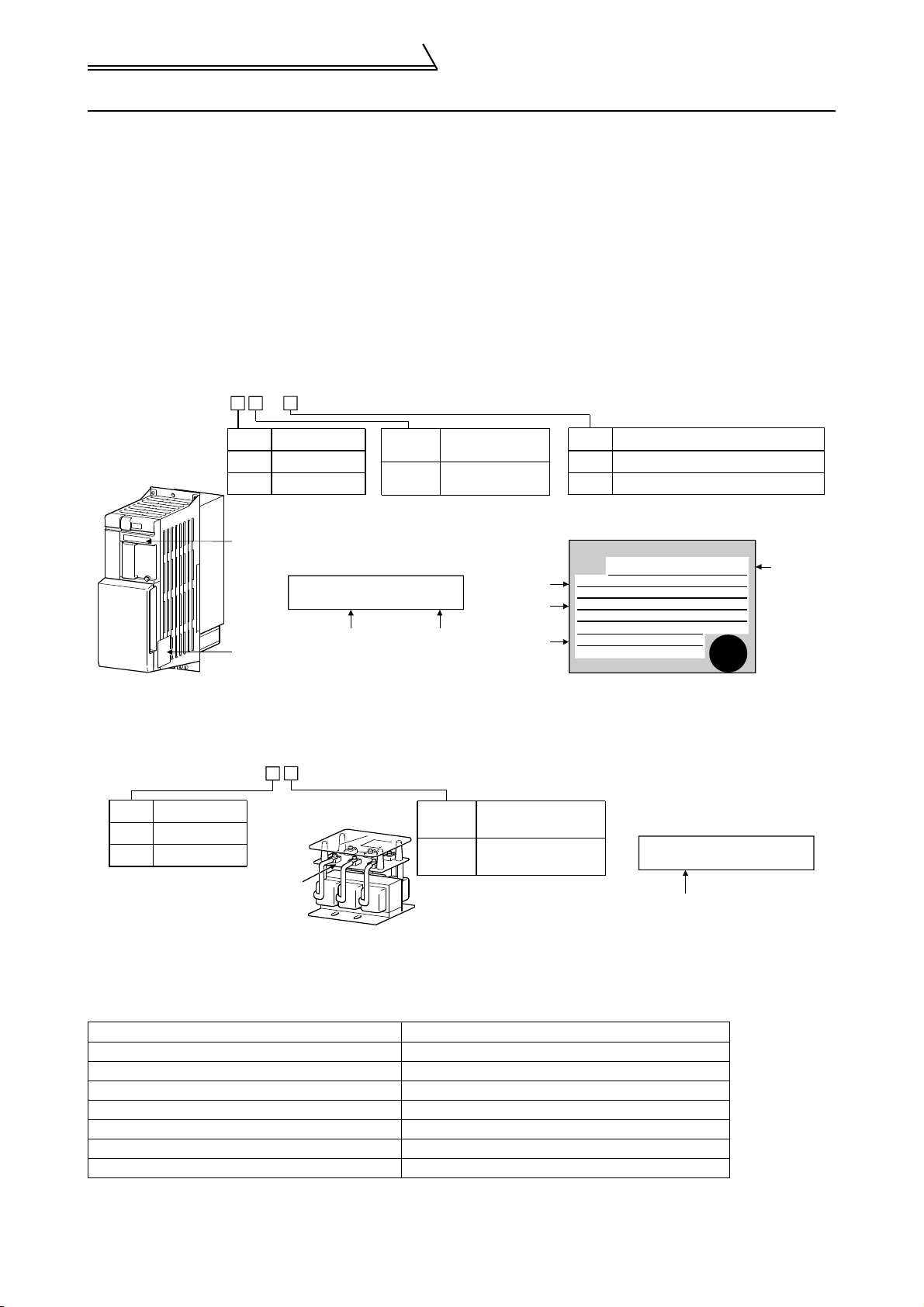
(1) Unpacking and product check
Unpack the power regeneration common converter and check the capacity plate on the front cover and the rating
plate on the inverter side face to ensure that the product agrees with your order and the inverter is intact.
1) Definition of the power regeneration common converter type
FR-CV- K-
Symbol
None
H
Voltage class
200V class
400V class
Symbol
7.5 to 55
Applicable Inverter
Capacity
Indicates capacity
in "kW".
Capacity plate
Capactiy plate
FR-CV-11K
Converter type Serial number
Rating plate
Input rating
Output rating
Serial number
2) The power regeneration common converter accessory
Instruction manual
3) Definition of the dedicated stand-alone reactor
Remember to prepare the dedicated stand-alone reactor as it must be installed.
FR-CVL- K
Symbol
None
H
Voltage class
200V class
400V class
Capacity plate
Symbol
7.5 to 55
Applicable Converter
Capacity
Indicates capacity
in "kW".
Symbol
Heat sink outside mounting structure
None
Enclosure inside installation structure
AT
Structure
Rating plate
MITSUBISHI
MODEL
FR-CV-11K
XXXXX
INPUT :
XXXXX
OUTPUT :
SERIAL :
INVERTER
PASSED
Capacity plate
FR-CVL-11K
Reactor type
Converter
type
If you have found any discrepancy, damage, etc., please contact your sales representative.
(2) Confirmation of the peripheral device types
The dedicated stand-alone reactor must be installed.
Power regeneration common converter Dedicated stand-alone reactor (required)
FR-CV-7.5K(-AT) FR-CVL-7.5K
FR-CV-11K(-AT) FR-CVL-11K
FR-CV-15K(-AT) FR-CVL-15K
FR-CV-22K(-AT) FR-CVL-22K
FR-CV-30K(-AT) FR-CVL-30K
FR-CV-37K FR-CVL-37K
FR-CV-55K FR-CVL-55K
Note: 400Vclass devices have capacity numbers preceded by H in their type codes.
2
Page 8

Pre-Operation Information
(3) Installation
To operate the power regeneration common converter with high performance for a long time, install the inverter in a
proper place, in the correct direction, and with proper clearances. (Refer to page 10.)
(4) Wiring
Connect the power supply, inverter and control signals to the terminal block. Note that incorrect connection may
damage the power regeneration common converter , inverter and peripheral devices. (Refer to page 10.)
1
OUTLINE
3
Page 9
Basic Configuration
1.2 Basic Configuration
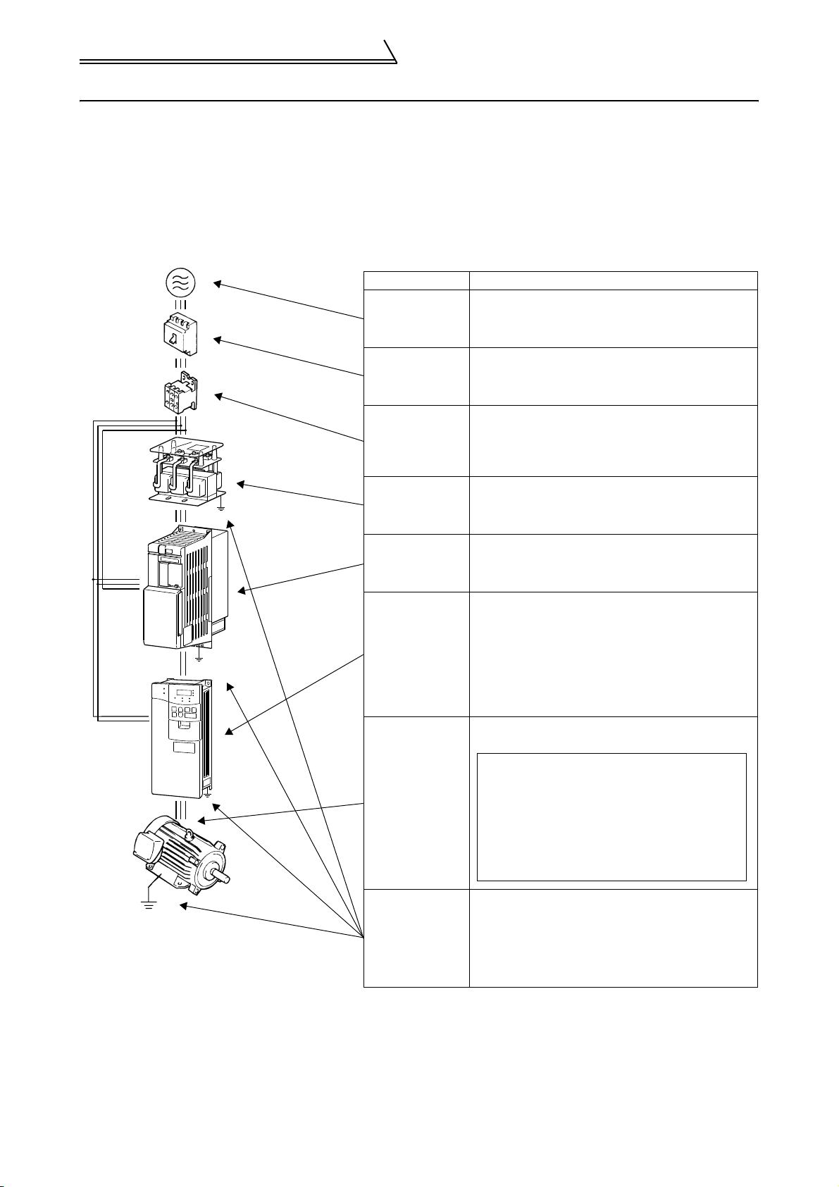
1.2.1 Basic configuration
The following devices are required to operate the power regeneration common converter. Proper peripheral devices
must be selected and correct connections made to ensure proper operation. Incorrect system configuration and
connections can cause the inverter to operate improperly, its life to be reduced considerably, and in the worst case,
the inverter to be damaged.
Please handle the product properly in accordance with the information in each section as well as the precautions
and instructions of this manual. (For connections of the peripheral devices, refer to the corresponding manuals.)
Name Description
Use the power supply within the permissible power
(ELB)
or
(NFB)
(MC)
Dedicated Stand-alone
reactor (FR-CVL)
Earth(Ground)
Power regeneration
common converter
(FR-CV)
Earth
(Ground)
Power supply
Earth leakage
circuit breaker
(ELB) or no-fuse
breaker(NFB)
Magnetic
contactor
Installation of
dedicated
stand-alone
reactor
Power
regeneration
common
converter
Inverter
supply specifications of the power regeneration
common converter.
(Refer to page 44.)
The breaker should be selected with care since a
large inrush current flows in the power regeneration
common converter at power on. (Refer to page 26.)
Install the magnetic contactor to ensure safety.
When installed, do not use it to start or stop the
inverter. It might reduce the power regeneration
common converter life.
(Refer to page 26.)
For power coordination, always install the
dedicated stand-alone reactor.
Incorrect wiring might lead to power regeneration
common converter damage. The control signal lines
should be kept away from the main circuit to protect
them from noise.
•Use the compatible inverter.
•The inverter life is influenced by ambient
temperature.The ambient temperature should be
as low as possible within the permissible range.
This must be noted especially when the inverter is
installed in an enclosure .
•Incorrect wiring might lead to inverter damage.The
control signal lines should be kept away from the
main circuit to protect them from noise.
Do not connect a power capacitor, surge suppressor
or radio noise filter to the output side.
Note: Note that when an electromagnetic
contactor (MC) and a no-fuse breaker
(NFB) are installed, switching off the
inverter during operation, then on again
will cause a starting current to flow,
affecting the inverter and motor. When
installing a no-fuse breaker (NFB) on the
output side, contact the NFB manufacturer
for selection of no-fuse breaker.
To prevent an electric shock, always ground the
dedicated stand-alone reactor, power regeneration
common converter, motor and inverter.
The grounding cable provided for reduction of
induction noise from the power line of the inverter is
recommended to be wired by returning it to the
grounding terminal of the inverter.
Earth(Ground)
Earth
(Ground)
Devices
connected to the
output
Earth(Ground)
Note: If connected to the inverter, the power factor improving DC reactor (FR-BEL) does not produce an effect on
power factor improvement. In addition, do not use the power factor improving AC reactor (FR-BAL) since
using it may degrade the power regeneration function.
4
Page 10
1.3 Structure
r
r
)
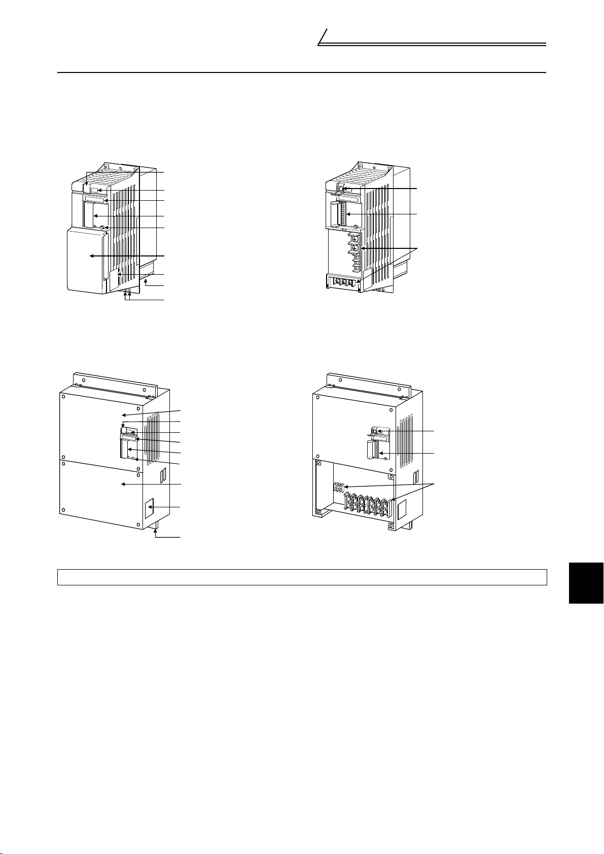
1.3.1 Appearance and structure
FR-CV-7.5K to 30K (-AT), FR-CV-H7.5K to H30K (-AT)
(1) Front view (2) Without front cover
Connector cover for manufacturer
setting
LED display
Capacity plate
Control circuit terminal block cove
CHARGE lamp
Connector for manufacturer
setting (Note)
Control circuit terminal block
Structure
Main cricuit terminal block cover
Main circuit terminal block
Rating plate
Cooling fan
Earth screws
FR-CV-37K/55K, FR-CV-H37K/H55K
(1) Front view (2) Without front cover
Front cover
Maker setting connector cover
LED display
Capacity plate
Control circuit terminal block cove
CHARGE lamp
Main circuit terminal block cover
Rating plate
Fix ture
Maker setting connector (Note
Control circuit terminal block
Main circuit terminal block
Note: Keep the connector for manufacturer setting open.
1
OUTLINE
5
Page 11
Structure
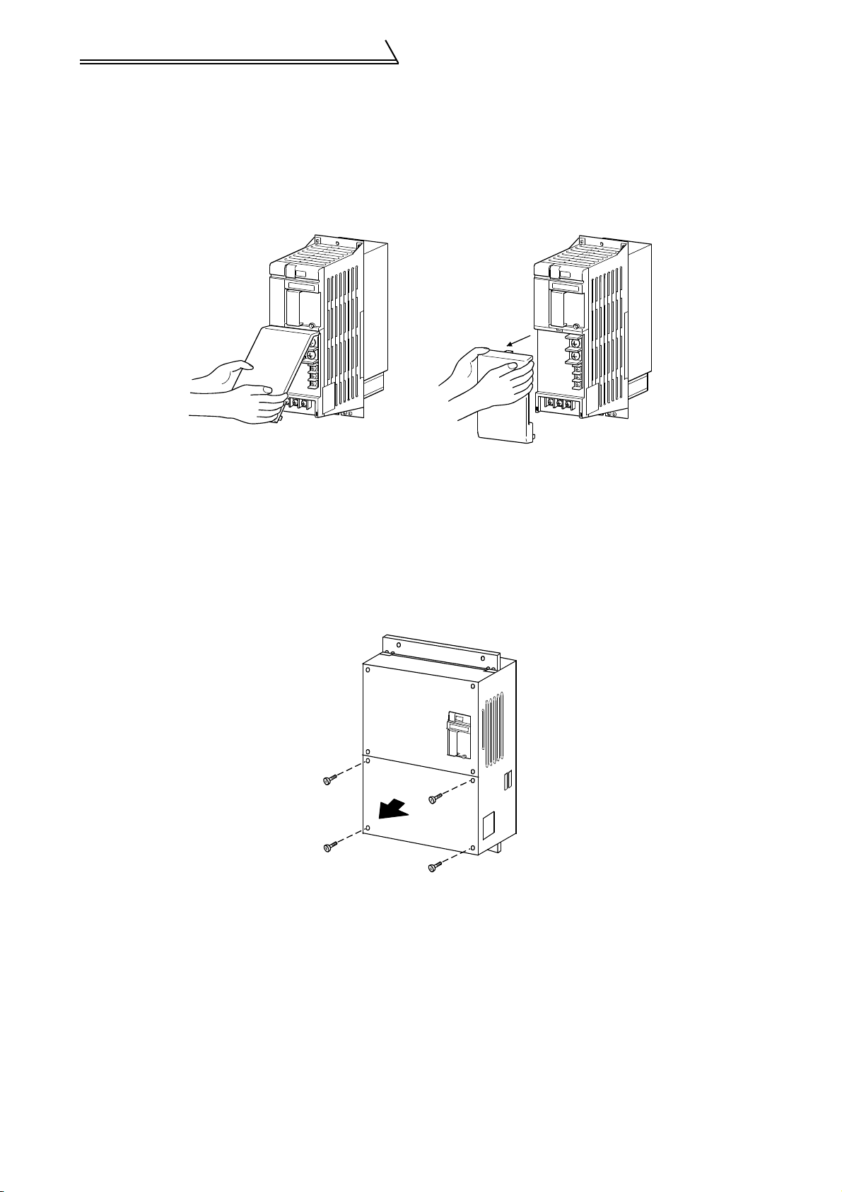
1.3.2 Removal and reinstallation
(1) Main circuit terminal block cover
FR-CV-7.5K to 30K (-AT), FR-CV-H7.5K to H30K(-AT)
zRemoval
1)Hold both ends of the cover bottom and pull it toward you.
2)When the bottom of the cover has come off, hold both ends of the cover top and pull it toward you.
zReinstallation
1)Insert the catch at the cover top into the socket in the unit.
2)Using the part of the catch as a support, securely press the catches at both ends of the cover bottom to
the unit.
FR-CV-37K/55K, FR-CV-H37K/H55K
zRemoval
1)Remove the installation screws at the top of the main circuit terminal block cover.
zReinstallation
1)Fix the main circuit terminal block cover with the installation screws.
6
Page 12
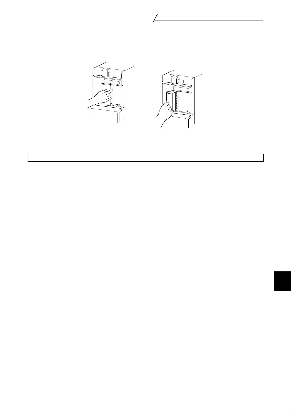
(2) Control circuit terminal block cover
zOpening
1)Hold the right end of the cover and pull it toward you.
2)The cover opens, with the left-hand side of the cover acting as a support.
zClosing
1)Securely press the right end of the cover against the unit.
Note: Make sure that the cover has been fitted securely.
Structure
1
OUTLINE
7
Page 13
Structure
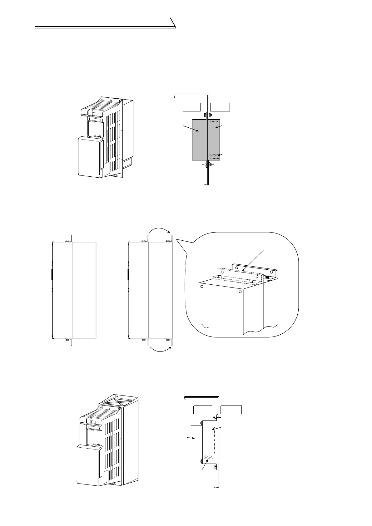
1.3.3 Structure of the power regeneration common converter
The power regeneration common converter is available in two types: a heat sink outside mounting structure model
and an enclosure inside installation structure model.
(1) Heat sink outside mounting structure model (FR-CV-7.5K to 55K, FR-CV-H7.5 to H55K)
Enclosure
Inside
Power regeneration
common converter
Outside
Heat
sink
Cooling
fan
The FR-CV-37K, 55K and FR-CV-H37K, H55K can be used either as a heat sink outside mounting structure model
or an enclosure inside installation structure model by changing its mounting foot position. It is shipped from the
factory as a heat sink outside mounting structure model. Change the mounting foot position as shown below for
installation.
Factory-set mounting
foot position
Heat sink outside mounting
(At factory shipment)
Enclosure inside installation
(2) Enclosure inside installation structure model
(FR-CV-7.5K to 30K-AT, FR-CV-H7.5K to H30K-AT)
Enclosure
Power regeneration
common converter
Cooling fan
8
Inside
Outside
Heat
sink
Page 14

CHAPTER 2
INSTALLATION AND WIRING
This chapter gives information on the basic "Installation and
wiring" of this product.
Always read the instructions in this chapter before using the
equipment.
2.1 Installation ................................................... 10
2.2 Wiring........................................................... 12
2.3 Operation ..................................................... 23
2.4 Other wiring................................................. 24
1
2
3
4
9
Page 15

Installation
2.1 Installation
2.1.1 Instructions for installation
1) Handle the unit carefully.
The power regeneration common converter uses plastic parts. Handle it gently to protect it from damage. Also,
hold the unit with even strength and do not apply too much strength to the terminal block cover alone.
2) Install the inverter in a place where it is immune to vibration. (5.9 m/s
Also note the cart, press, etc.
3) Note on ambient temperature
The power regeneration common converter life is under great influence of ambient temperature. Exercise care
so that the ambient temperatures of the installation place do not fall out of the permissible range (-10°C to
+50°C (14°F to 120°F)). Make sure that the ambient temperatures are within the permissible range at the
measurement positions given in 3) on the next page. It is important to check that not only the ambient
temperatures of the power regeneration common converter but also those of the inverter contained in the same
enclosure fall within the permissible range.
4) Notes on installation surface
The power regeneration common converter will be very hot (maximum about 150°C (302°F)).
The power regeneration common converter (heat sink outside mounting structure model) can be reduced in the
enclosure inside temperature by mounting its heat sink outside the enclosure. Cut the mounting area according
to the panel cutting dimensions. Since the cooling section located outside the enclosure has a cooling fan, do
not use the equipment in the environment that has water drops, oil mists, dust particles, etc. For installation in
an enclosure, use the enclosure inside installation structure model of the power regeneration common
converter and install it on an incombustible (e.g. metal) mounting surface.
Also leave sufficient clearances around the inverter.
5) Avoid high temperature and high humidity.
Avoid direct sunlight and places of high temperature and high humidity.
2
or less)
6) Avoid places where the inverter option is exposed to oil mist, flammable gases, fluff, dust, dirt etc.
Install the inverter option in a clean place or inside a "totally enclosed" panel which does not accept any
suspended matter.
7) Note the cooling method when the power regeneration common converter and inverter is installed in an
enclosure.
When two or more power regeneration common converters and inverters are installed or a ventilation fan is
mounted in an enclosure, the inverters and ventilation fan must be installed in proper positions with extreme
care taken to keep the ambient temperatures of the power regeneration common converters and inverters
below the permissible value. If they are installed in improper positions, the ambient temperatures of the power
regeneration common converters and inverters will rise and ventilation effect will be reduced.
8) Install the power regeneration common converter and inverter securely in the vertical direction with screws or
bolts.
9) Install the dedicated stand-alone reactor (FR-CVL) on horizontal plane. Failure to observe this may lead to
damage of the reactor.
10
Page 16
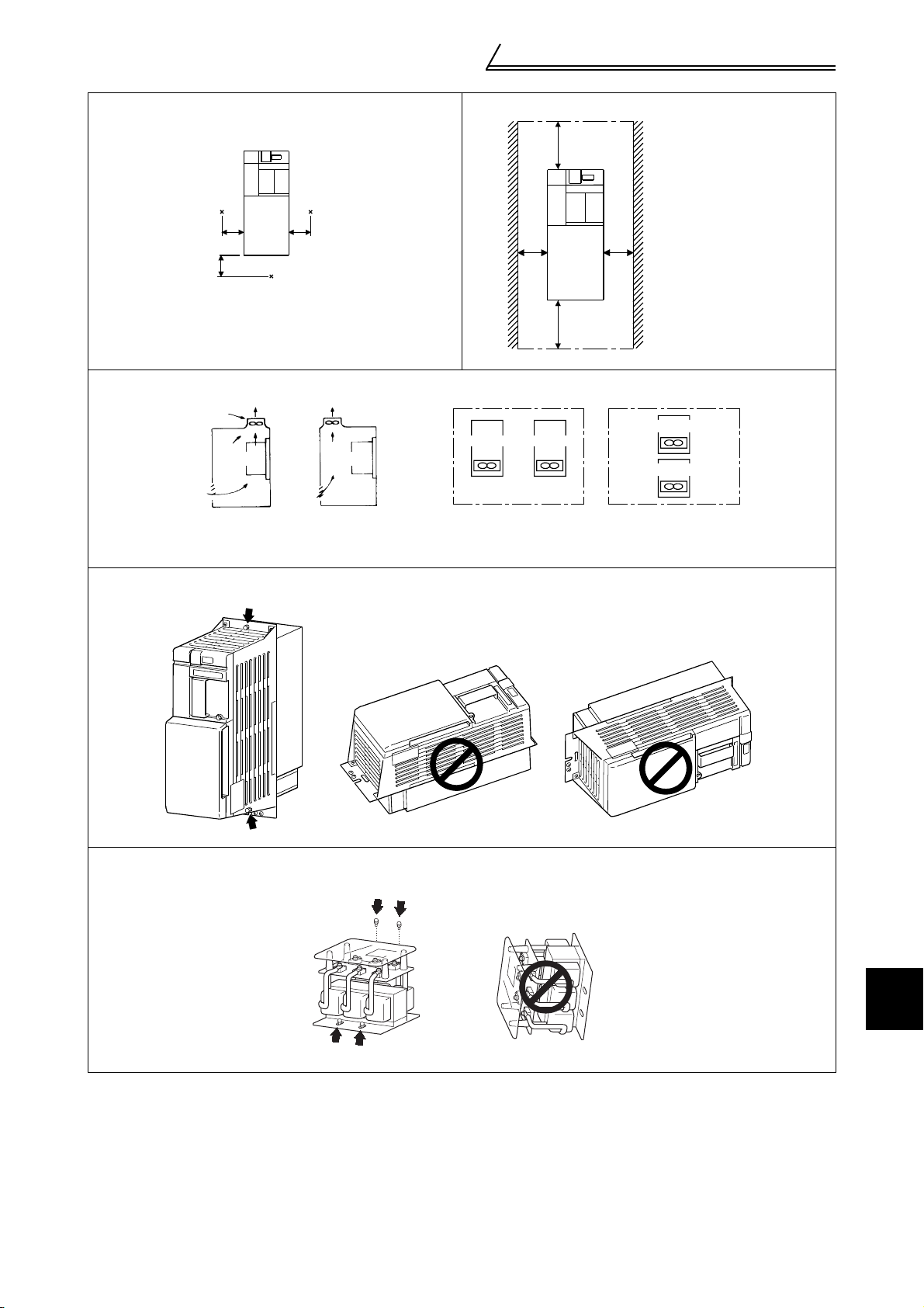
3) Note on ambient temperature 4) Clearances around the inverter
p
10cm
(3.94 inches)
or more
Measurement
position
5cm
(1.97 inches)
5cm
(1.97 inches)
FR-CV
5cm
(1.97 inches)
Measurement
osition
or moer
5cm (1.97 inches)
FR-CV
10cm
(3.94 inches)
or more
or moer
5cm (1.97 inches)
7) For installation in an enclosure
Ventilation
fan
Converter
(Correct example)
Position of Ventilation Fan
Converter
(Incorrect example)
Converter
Built-in cooling fan
Converter
(Correct example)
Accommodation of two or more inverters
Converter
Converter
(Incorrect example)
Installation
Clearances required to
change the cooling fan of
the enclosure inside
installation structure model
(-AT). (Refer to page 36 for
fan replacement.)
8) Vertical mounting
Power regeneration common converter
9) Horizontal plane installation
Dedicated stand-alone reactor
INSTALLATION AND WIRING
2
11
Page 17
Wiring
2.2 Wiring
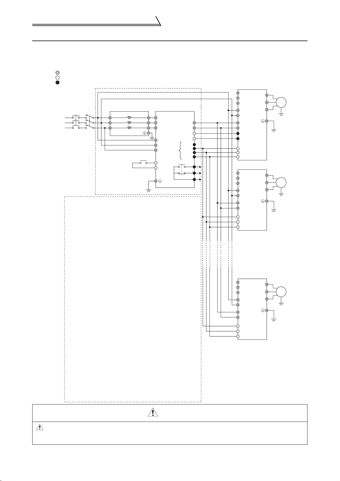
2.2.1 Terminal connection diagram
Main circuit terminal
Control circuit input terminal
Control circuit output terminal
MCNFB
R
S
T
3-phase
AC power supply
Note : 1. Never connect a power supply to the inverter terminals R, S, T.
Such a connection, even if accidental, will damage the inverter
and power regeneration common converter.
2. Match the polarities of the P and N terminals by connecting
terminal P of the inverter to terminal P of the power
regeneration common converter and terminal N of the inverter
to terminal N of the power regeneration common converter as
shown in the connection example. Incorrect matching of
the polarities of the P and N terminals will result in damage
to the inverter.
Do not remove a jumper across terminal P/+ and P1.
3. For the FR-A700, F700, A500, F500 and V500 series, remove
the jumpers across terminals R-R1 and S-S1, and connect
power supply to terminals R1, S1 for the control circuit. For the
FR-E700, D700, E500, S500, C500 and F500J series, the
inverter does not have terminals R1, S1. So you do not need to
make this connection.
4. When wiring the dedicated stand-alone reactor and power
regeneration common converter as well as when wiring
the power supply and terminals R/L11, S/L21, T/MC1, strictly
observe the wiring order as shown in the connection example
(match phase sequence of the power supply).
A wrong connection will damage the power regeneration
common converter.
Do not insert an MCCB nor MC. The power regeneration
common converter functions abnormally.
5. Make sure terminals R/L11, S/L21, T/MC1 are connected to
the power supply. Running the inverter without connecting
these terminals will damage the power regeneration common
converter.
6. Since power to the inverter is supplied by terminals P and N,
set Pr.30 to 2 (for use with a high power factor converter, power
regeneration common converter) for the FR-A700, F700, A500,
F500 and V500 series. This setting disables the built-in brake
resistor.
7. For the FR-A700, F700, E700, D700, A500, F500 and V500
series inverter, assign the X10 signal to any of input terminals to
use the inverter.
8. You can connect up to six inverters to one power regeneration
common converter.
9. Use sink logic (factory setting) when the FR-CV is connected.
The FR-CV cannot be connected when source logic is selected.
FR-CVL
(Note 4)
R/L11
S/L21
T/L31
R2/L12
S2/L22
T2/L32
(Note 5)
(Note 4)
R2/L1
S2/L2
T2/L3
R/L11
S/L21
T/MC1
RES
SD
FR-CV
P/L+
N/L-
RDYA
RDYB
RS0
SE
Open collector
outputs
P24
SD
A
B
C
FR-A720
R/L1
S/L2
(Note 1)
T/L3
R1/L11
(Note 3)
S1/L21
P/+
(Note 2)
N/PC
SD
(Note 7)
X10 (MRS)
RES
SD
FR-A720
R/L1
(Note 1)
S/L2
T/L3
R1/L11
(Note 3)
S1/L21
P/+
(Note 2)
N/-
(Note 7)
X10 (MRS)
RES
SD
FR-A720
R/L1
(Note 1)
S/L2
T/L3
R1/L11
(Note 3)
S1/L21
P/+
(Note 2)
N/-
(Note 7)
X10 (MRS)
RES
SD
U
V
W
U
V
W
U
V
W
IM
IM
IM
CAUTION
Be sure to connect terminal RDY of the FR-CV to the X10 or MRS signal assigned terminal of the
inverter, and connect terminal SE of the FR-CV to terminal SD of the inverter. Without proper
connecting, FR-CV will be damaged.
12
Page 18
(1) Description of main circuit terminals
Symbol Terminal Name Description
R2/L1, S2/
L2,T2/L3
P/L+, N/L- DC power output
R/L11, S/
L21, T/MC1
AC power input Connect to the dedicated stand-alone reactor terminals R2/L12, S2/L22, T2/L32.
Connect to the inverter terminals P, N, and keep the inverter terminals R, S, T open.
For the FR-A700, F700, A500, F500 or V500 series, set 2 (for use of high power
factor converter, power regeneration common converter) in Pr.30.
Power supply phase
detection
Ground Securely connect to the earth.
Terminals for power supply phase, power voltage detection and control power input.
Connect to the dedicated stand-alone reactor terminals R/L11, S/L21, T/L31.
Running the inverter without connecting these terminals will damage the power
regeneration common converter.
(2) Description of control circuit terminals
Type Symbol Terminal Name Description
Used to input 24VDC power for alarm output relay drive and reset drive signal
P24 24VDC input
RES Reset
Input signals
SD
Power input, contact
RDYA Ready output
RDYB
Open collector
RSO Converter reset
Output signals
SE
A, B, C Alarm output
Contact
24VDC power common
Contact input common
Inverter
operation enable
Open collector output
common
drive. Connect to the inverter terminal PC. When you do not use the inverter
terminal PC, prepare a 24VDC power supply.
Permissible input voltage fluctuation: 22V to 26VDC
Used to reset the activated protective circuit. Turn the terminals RES-SD on for
longer than 0.1 seconds, then turn them off.
Connect the common of the 24VDC power supply.
Shorting the terminal RES and this terminal inputs the reset signal.
Outputs a signal when the power regeneration common converter is ready to
operate.
This output has opposite logic to RDYB.
Permissible load 24V 0.1ADC
Outputs a signal when the power regeneration common converter is faulty or the
reset signal is input. Connect to the X10 (MRS) signal of the inverter. This output
has opposite logic to RDYA.
Permissible load 24V 0.1ADC
Outputs the reset signal to the inverter when the reset signal is input to the power
regeneration common converter. Connect to the inverter terminal RES.
Permissible load 24V 0.1ADC
Common to the terminals RDYA, RDYB and RSO. Connect to the inverter
terminal SD.
Change-over outputs which indicate that the protective function of the power
regeneration common converter was activated to stop the output.
Alarm: No continuity across B-C (continuity across A-C), normal: Continuity across
B-C (no continuity across A-C)
Permissible load 230V 0.3AAC, 30V 0.3ADC
Wiring
(3) Description of inverter connection terminals
Type Symbol Terminal Name Description
P, N DC power input Connect to the power regeneration common converter terminals P/L+, N/L-.
For the FR-A700, F700, A500, F500 or V500 series, remove the jumpers across
R1, S1
Main circuit
X10
(MRS)
RES Converter reset
Control circuit
PC 24VDC power
SD Contact input common
Control circuit power
input
Ground Securely connect to the earth.
Output stop
Note: When used as the 24V power, the terminal PC cannot prevent a sneak path for transistor output.
the inverter terminals R-R1 and S-S1, and input external power to these terminals.
For the FR-E500, S500, C500 or F500J series, the inverter does not have the
terminals R1, S1 so uses the DC power input from the terminals P, N as the control
power.
Shuts off the inverter output when the power regeneration common converter is
faulty or the converter reset signal is input. Connect to the power regeneration
common converter terminal RDYB. For the FR-A700, F700, E700, D700, A500,
F500 or V500 series, assign the X10 signal to any of the input terminals. For the
FR-E500, S500, C500 or F500J series, use the terminal MRS as you cannot
assign the X10 signal. If the terminal MRS is already used, assign another MRS
signal to any of the input terminals.
When the reset signal is input to the power regeneration common converter, the
reset signal is also input to the inverter. Connect to the power regeneration
common converter terminal RSO. For the D700, S500, C500 and F500J series,
assign the RES signal to any one of the input terminals.
24V 0.1ADC power. Connect to the power regeneration common converter
terminal P24.(Note)
Common to the contact input terminals. Also acts as a common to the 24V
0.1ADC power (terminal PC).
INSTALLATION AND WIRING
2
13
Page 19
Wiring
2.2.2 Wiring of the main circuit
(1) Wiring instructions
1) Crimping terminals with insulation sleeves are recommended for use with the power and inverter cables.
2) Strictly observe the order of wiring in the connection example when performing wiring between the dedicated
stand-alone reactor and power regeneration common converter and wiring between the power supply and
terminals R/L11, S/L21, T/MC1. (Match the phase sequence of the power supply.) Incorrect connection will
damage the power regeneration common converter.
3) Make sure to connect the terminal R/L11, S/L21, T/MC1 to the power supply.
Running the inverter without connecting the terminals will damage the power regeneration common converter.
4) Connect a DC power supply between the power regeneration common converter and inverter with correct
polarity.
5) After wiring, wire off-cuts must not be left in the power regeneration common converter.
Wire off-cuts can cause an alarm, failure or malfunction. Always keep the power regeneration common
converter clean.
When drilling mounting holes in a control box etc., exercise care to prevent chips and other foreign matter from
entering the power regeneration common converter.
6) Electromagnetic wave interference
The input/output (main circuit) of the power regeneration common converter and inverter includes harmonic
components, which may interfere with the communication devices (such as AM radios) used near the power
regeneration common converter and inverter. In this case, install the FR-BIF optional radio noise filter (for use
in the input side only) or FR-BSF01 or FR-BLF line noise filter to minimize interference.
7) When rewiring after operation, make sure that the CHARGE lamp has gone off, and when more than 10
minutes have elapsed after power-off, check with a meter that the voltage is zero. After that, start rewiring work.
For some time after power-off, there is a dangerous voltage in the capacitor.
8) Be sure to connect terminal RDY of the FR-CV to the X10 or MRS signal assigned terminal of the inverter, and
connect terminal SE of the FR-CV to terminal SD of the inverter. Without proper connecting, FR-CV will be
damaged.
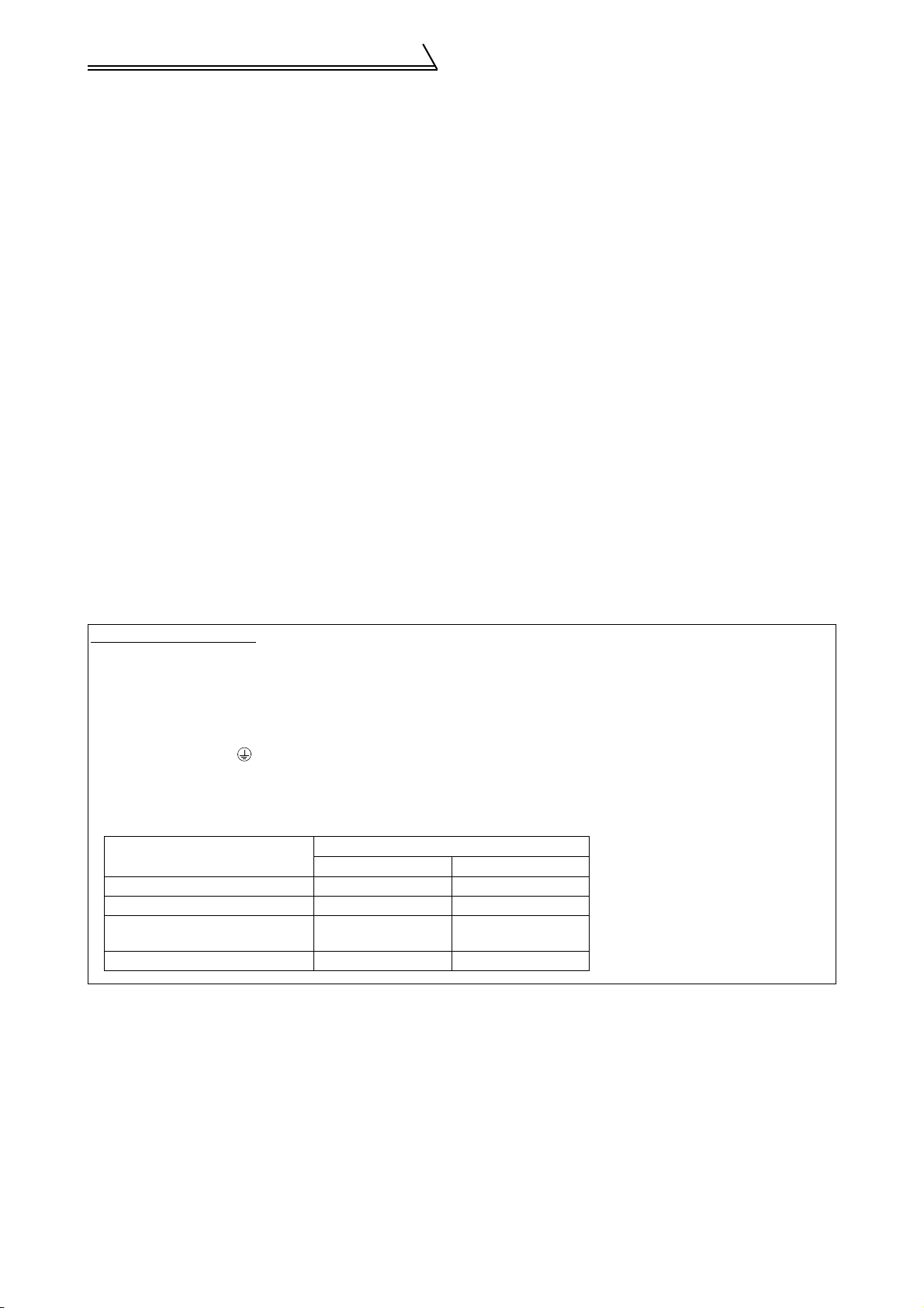
Notes on Grounding
z To prevent an electric shock, the dedicated stand-alone reactor, power regeneration common converter, inverter and
motor must be grounded.
z Use the dedicated ground terminal to ground the power regeneration common converter. (Do not use the screws in
the case, chassis, etc.)
z Use the reactor mounting screw to earth the dedicated stand-alone reactor.
Use the screw in the marked .
z The ground cable should be as thick as possible. Its gauge should be equal to or larger than those indicated in the
following table. The grounding point should be as near as possible to the power regeneration common converter to
minimize the ground cable length.
(Unit: mm
Capacity
7.5kW (10HP) 5.5 3.5
11kW, 15kW (15HP, 20HP) 14 8
22kW to 37kW
(30 to 50HP)
55kW (75HP) 38 22
Ground Cable Gauge
200V class 400V class
22 14
2
)
14
Page 20

Wiring
(2) Terminal block layout of the power circuit
In the main circuit of the power regeneration common converter, the terminals are arranged as shown below:
FR-CV-7.5K/11K(-AT) FR-CV-15K(-AT), FR-CV-H7.5K/H11K/H15K(-AT)
L+
<DC power output
terminals>
Connect to inverter
P and N terminals.
P
N
<Supply phase detection
terminals>
Connect to FR-CVL R,S and
T terminals (main supp ly).
<AC power supply input termin als>
Connect to FR-CVL R2, S2 and T2
terminals (secondary side).
R2 S2 T2
L+
L-
R
S
T
L11
L21
MC1
Screw size
(M6)
Screw size
(M4)
<DC power output
terminals>
Connect to inverter
P and N terminals.
<Supply phase detection
terminals>
Connect to FR-CVL R, S and
T terminals (main supply).
<AC power supply input terminals>
Connect to FR-CVL R2, S2 and T2
terminals (secondary side).
R2 S2 T2
P
Screw size
L-
N
R
L11
S
L21
MC1
T
Screw size
(M6)
(M4)
L1 L2 L3
Screw size
(M4)
Screw size
(M5)
FR-CV-22K/30K(-AT), FR-CV-H22K/H30K(-AT)
<DC power output terminals>
Connect to inverter P and N
terminals.
<Supply phase detection terminals>
Connect to FR-CVL R, S and T
terminals (main supply).
<AC power supply input terminals>
Connect to FR-CVL R2, S2 and T2
terminals (secondary side).
Screw size
(M5)
P
N
L+
L-
RTL11
S
L21
MC1
Screw size
(M5)
L1 L2 L3
Screw size
(M5)
Screw size
(M6)
Screw size
(M4)
R2 S2 T2
L1 L2 L3
15
INSTALLATION AND WIRING
2
Screw size
(M8)
Screw size
(M8)
Page 21

Wiring
FR-CV-37K
FR-CV-55K
Screw size
T/MC1
R/L11
S/L21
<Supply phase detectio n
terminals>
Connect to FR-CVL R, S and
T terminals (main supply)
Screw size
(M8)
Screw size
R/L11 S/L21 T/MC1
(M4)
(M4)
R2/L1 S2/L2
T2/L3
<AC power supply input termin als>
Connect to FR-CVL R2, S2, and T2
terminals (secondary side)
Screw size
(M10)
N/L-
<DC power output terminals>
Connect to invertor P and
N terminals
P/L+
<Supply phase detect ion
terminals>
Connect to FR-CVL R, S and
T terminals (main supply)
Screw size
FR-CV-H37K/H55K
Screw size (M4)
R/L11
<Supply phase detection terminals>
Connect to FR-CVL R, S and T
terminals (main supply)
4-55
(M8)
S/L21
T/MC1
C172D295H03
R2/L1 S2/L2 T2/L3 N/L- P/L+
<AC power supply input
terminals>
Connect to FR-CVL R2,
S2,and T2 terminals
(secondary side)
<DC power output
terminals>
Connect to invertor P
and N terminals
Screw size
(M12)
R2/L1 S2/L2 T2/L3
<AC power supply input terminals>
Connect to FR-CVL R2, S2 and T2
terminals (secondary side)
N/L- P/L+
<DC power output terminals>
Connect to inverter P and N
terminals
C172C295H02
Screw size
(M8)
Screw size
(M8)
16
Page 22

Wiring
(3) Cables, crimping terminals, etc.
Refer to the following for the cables, crimping terminals and terminal tightening torques used for the power
regeneration common converter.
MCNFB
3-phase
AC power supply
1)
FR-CVL
R/L11
S/L21
T/L31
4)
R2/L12
S2/L22
T2/L32
5)
FR-CV
2)
R2/L1
S2/L2
T2/L3
R/L11
S/L21
T/MC1
P/L+
N/L-
3)
(Note 3)
FR-A720
R/L1
S/L2
T/L3
R1/L11
S1/L21
P/
+
N/-
FR-A720
R/L1
S/L2
T/L3
R1/L11
S1/L21
P/
+
N/-
U
V
W
U
V
W
IM
IM
Note: 1. The cables used should be 75°C (167F°) copper cables.
2. Tighten the terminal screws to the specified torques.
Undertightening can cause a short or misoperation.
Overtightening can cause the screws and unit to be damaged, resulting in a short or misoperation.
3. Do not insert the NFB between terminals P - N (P/L+ - P/+, N/L- - N/-).
FR-A720
R/L1
S/L2
T/L3
R1/L11
S1/L21
P/
+
N/-
U
V
W
IM
INSTALLATION AND WIRING
2
17
Page 23

Wiring
)
1) Connection of power supply and dedicated stand-alone reactor
Dedicated
MCNFB
stand-alone reactor (FR-CVL
1)
R/L11
S/L21
T/L31
R2/L12
S2/L22
T2/L32
Dedicated
Stand-Alone
Terminal Name
Reactor Model
FR-CVL-7.5K
FR-CVL-11K M5 2.5 14-5 14 6
FR-CVL-15K M6 4.4 22-6 22 4
FR-CVL-22K M6 4.4 38-6 38 2
FR-CVL-30K M6 4.4 60-6 60 1/0
FR-CVL-37K M10 14.7 100-10 100 4/0
FR-CVL-55K M10 14.7 150-10 150 MCM300
FR-CVL-H7.5K M5 2.5 3.5-5 3.5 12
FR-CVL-H11K M5 2.5 5.5-5 5.5 10
FR-CVL-H15K M5 2.5 14-5 14 6
FR-CVL-H22K M6 4.4 22-6 22 4
FR-CVL-H30K M6 4.4 22-6 22 4
FR-CVL-H37K M8 7.8 38-8 38 2
FR-CVL-H55K M8 7.8 60-8 60 1/0
R/L11, S/L21,
T/L31
Termi nal
Screw Size
M5 2.5 14-5 14 6
Tightening
Torque N•m
Crimping
Termi nals
mm
Cables
2
AWG
Note: Wire the cables so that the phase sequence is always identical to those of the wiring in 2) and 4).
Connection in wrong phase sequence will damage the power regeneration common converter.
2) Connection of dedicated stand-alone reactor and power regeneration common converter
Dedicated
stand-alone reactor (FR-CVL)
R/L11
S/L21
T/L31
R2/L12
S2/L22
T2/L32
2)
FR-CV
R2/L1
S2/L2
T2/L3
10m
(32.81 feet)
maximum
Dedicated
Stand-Alone
Terminal Name
Reactor Model
FR-CVL-7.5K
FR-CVL-11K M5 2.5 14-5 14 6
FR-CVL-15K M6 4.4 22-6 22 4
FR-CVL-22K M6 4.4 38-6 38 2
FR-CVL-30K M6 4.4 60-6 60 1/0
FR-CVL-37K M10 14.7 100-10 100 4/0
FR-CVL-55K M10 14.7 150-10 150 MCM300
FR-CVL-H7.5K M5 2.5 3.5-5 3.5 12
FR-CVL-H11K M5 2.5 5.5-5 5.5 10
FR-CVL-H15K M5 2.5 14-5 14 6
FR-CVL-H22K M6 4.4 22-6 22 4
FR-CVL-H30K M6 4.4 22-6 22 4
FR-CVL-H37K M8 7.8 38-8 38 2
FR-CVL-H55K M8 7.8 60-8 60 1/0
R2/L12, S2/L22,
T2/L32
Termi nal
Screw Size
M5 2.5 14-5 14 6
Tightening
Torque N•m
Crimping
Termi nals
mm
Cables
2
AWG
18
Page 24

Wiring
Power
Regeneration
Common
Terminal Name
Terminal
Screw Size
Tightening
Tor q u e N•m
Crimping
Terminals
mm
Cables
2
AWG
Converter Model
FR-CV-7.5K
FR-CV-11K M5 2.5 14-5 14 6
FR-CV-15K M5 2.5
FR-CV-22K M8 7.8 38-8 38 2
FR-CV-30K M8 7.8
FR-CV-37K M10 14.7 100-10 100 4/0
FR-CV-55K M12 24.5 150-12 150 MCM300
FR-CV-H7.5K M5 2.5 3.5-5 3.5 12
FR-CV-H11K M5 2.5 5.5-5 5.5 10
FR-CV-H15K M5 2.5 14-5 14 6
FR-CV-H22K M8 7.8 22-8 22 4
FR-CV-H30K M8 7.8 22-8 22 4
FR-CV-H37K M8 7.8 38-8 38 2
FR-CV-H55K M8 7.8 60-8 60 1/0
R2/L1, S2/L2,
T2/L3
M5 2.5 14-5 14 6
22-S6
(Note 2)
CB60-S8
(Note 2)
22 4
60 1/0
Note: 1. Wire the cables so that the phase sequence is always identical to those of the wiring in 1) and 4).
Connection in wrong phase sequence will damage the power regeneration common converter.
2. Manufactured by J.S.T.
3) Connection of power regeneration common converter and inverter
FR-A520
R
S
T
R1
S1
P/+
N/-
R2/L1
S2/L2
T2/L3
R/L11
S/L21
T/MC1
FR-CV
P/L+
N/L-
3)
5m (16.40 feet)
maximum
Note: Do not insert the NFB between terminals P - N (P/L+ - P/+, N/L- - N/-).
Do not remove a jumper across terminal P/+ and P1.
Power
Regeneration
Common
Terminal Name
Terminal
Screw Size
Tightening
Tor q u e N•m
Crimping
Terminals
mm
Cables
2
AWG
Converter Model
FR-CV-7.5K
FR-CV-11K M6 4.4 14-6 14 6
FR-CV-15K M6 4.4 22-6 22 4
FR-CV-22K M6 4.4
FR-CV-30K M6 4.4
FR-CV-37K M10 14.7 100-10 100 4/0
FR-CV-55K M12 24.5 150-12 150 MCM300
FR-CV-H7.5K M6 4.4 3.5-6 3.5 12
FR-CV-H11K M6 4.4 5.5-6 5.5 10
FR-CV-H15K M6 4.4 14-6 14 6
FR-CV-H22K M6 4.4 22-6 22 4
FR-CV-H30K M6 4.4 22-6 22 4
FR-CV-H37K M8 7.8 38-8 38 2
FR-CV-H55K M8 7.8 60-8 60 1/0
P/L+, N/L-
M6 4.4 14-6 14 6
38-S6
(Note 2)
CB60-S6
(Note 2)
38 2
60 1/0
19
INSTALLATION AND WIRING
2
Page 25

Wiring
«Example of connecting two or more inverters»
You can connect up to six inverters to one power regeneration common converter. The capacity of the power
regeneration common converter should always be greater than the sum of the connected inverter capacities or
the sum of rated inverter currents.
zWhen connecting several inverters, pay attention to the selection of the cables sizes since junction terminals or
jumper cables are used to wire the terminals P, N of the inverters. Make selection so that the inverter
capacities are added in order, starting with the one of the remotest inverter.
zWhen connecting several inverters, connect the inverters in order of larger capacities.
zSpecific example
R2/L1
S2/L2
T2/L3
R/L11
S/L21
T/MC1
P/L+
N/L-
FR-CV-22K
FR-A720-11K
3)
Overall wiring length
=5m (16.40 feet) maximum
P/+
N/-
FR-A720-5.5K
P/+
N/-
FR-A720-3.7K
P/+
N/-
First inverter: Choose 38mm assuming
that the converter capacity
is 22K according to the sum
of inverter capacities,
11K+5.5K+3.7K=20.2K.
Second inverter: Choose 14mm assuming
that the converter capacity is
11K according to the sum of
inverter capacities,
5.5K+3.7K=9.2K.
Third inverter: Choose 3.5mm according to
the inverter capacity, 3.7K.
2
2
2
Note: 1. Correctly connect the terminals P/L+, N/L- with the inverter terminals P, N.
Wrong connection will damage the power regeneration common converter.
2. Do not insert the NFB between terminals P - N (P/L+ - P/+, N/L- - N/-, P/+ - P/+, N/- - N/-).
3. Manufactured by J.S.T.
4) Connection of power supply and power regeneration common converter (power supply phase detection
terminals)
R/L11
S/L21
T/L31
R2/L12
S2/L22
T2/L32
R2/L1
S2/L2
T2/L3
Dedicated
Stand-Alone
Reactor Model
FR-CVL-7.5K
4)
10m (32.81 feet) maximum
Terminal Name
R/L11
S/L21
T/MC1
mm
Cables
2
Termi nal
Screw Size
Tightening
Torque N•m
Crimping
Termi nals
M5 2.5 1.25-5 1.25 16
AWG
FR-CVL-11K M5 2.5 1.25-5 1.25 16
FR-CVL-15K M6 4.4 1.25-6 1.25 16
FR-CVL-22K M6 4.4 1.25-6 1.25 16
FR-CVL-30K M6 4.4 1.25-6 1.25 16
FR-CVL-37K M10 14.7 1.25-10 1.25 16
FR-CVL-55K M10 14.7 1.25-10 1.25 16
FR-CVL-H7.5K M5 2.5 1.25-5 1.25 16
R/L11, S/L21,
T/L31
FR-CVL-H11K M5 2.5 1.25-5 1.25 16
FR-CVL-H15K M5 2.5 1.25-5 1.25 16
FR-CVL-H22K M6 4.4 1.25-6 1.25 16
FR-CVL-H30K M6 4.4 1.25-6 1.25 16
FR-CVL-H37K M8 7.8 1.25-8 1.25 16
FR-CVL-H55K M8 7.8 1.25-8 1.25 16
20
Page 26

Wiring
Power
Regeneration
Common
Terminal Name
Terminal
Screw Size
Tightening
Tor q u e N•m
Crimping
Terminals
mm
Cables
2
AWG
Converter Model
FR-CV-7.5K
FR-CV-11K M4 1.5 1.25-4 1.25 16
FR-CV-15K M4 1.5 1.25-4 1.25 16
FR-CV-22K M4 1.5 1.25-4 1.25 16
FR-CV-30K M4 1.5 1.25-4 1.25 16
FR-CV-37K M4 1.5 1.25-4 1.25 16
FR-CV-55K M4 1.5 1.25-4 1.25 16
FR-CV-H7.5K M4 1.5 1.25-4 1.25 16
FR-CV-H11K M4 1.5 1.25-4 1.25 16
FR-CV-H15K M4 1.5 1.25-4 1.25 16
FR-CV-H22K M4 1.5 1.25-4 1.25 16
FR-CV-H30K M4 1.5 1.25-4 1.25 16
FR-CV-H37K M4 1.5 1.25-4 1.25 16
FR-CV-H55K M4 1.5 1.25-4 1.25 16
R/L11, S/L21,
T/MC1
M4 1.5 1.25-4 1.25 16
Note: 1. Wire the cables so that the phase sequence of the wiring in 4) is always identical to those of the wiring in
1) and 2).
Connection in wrong phase sequence will damage the power regeneration common converter.
2. To prevent a malfunction due to noise, run the cables away from the main circuit wiring.
3. Running the inverter without connecting terminals R/L11, S/L21 and T/MC1 to the power supply will
damage the power regeneration common converter.
5) Connection of power supply and inverter
When the model used is the one whose control power is input from R1 and S1, control circuit power must be
input to R1 and S1 of the inverter. At this time, remove the jumpers across R-R1, S-S1.
Cable size: 0.75mm
2
to 2mm
2
FR-A720
R/L1
S/L2
T/L3
R1/L11
S1/L21
P/
+
N/-
(Note1)
(Note2)
Dedicated
stand-alone reactor (FR-CVL)
R/L11
S/L21
T/L31
R2/L12
S2/L22
T2/L32
R2/L1
S2/L2
T2/L3
R/L11
S/L21
T/MC1
5)
FR-CV
P/L+
N/L-
Note: 1. Never connect a power supply to the inverter terminals R, S, T. Accidental connection will damage the
inverter and power regeneration common converter.
2. For the FR-A700, F700, A500, F500 or V500 series, disconnect the jumpers across terminals R-R1, SS1 and connect the control power supply to terminals R1, S1. For the FR-E700, D700, E500, S500,
C500 or F500J series, there are no terminals R1, S1 and you need not make the above connection.
2.2.3 Wiring of the control circuit
(1) Wiring instructions
1) The terminals SD, SE are common to the I/O signals and are isolated from each other. Must not be earthed
(grounded).
2) Shielded or twisted cables must be used for connection to the control circuit terminals, and also run away from
the main and power circuits (including the 200V relay sequence circuit).
3) The input signals to the control circuit are micro currents. When contacts are required, use two or more parallel
micro signal contacts or a twin contact to prevent a contact fault.
4) It is recommended to use the cables of 0.3mm
terminals.
2
to 0.75mm2 gauge for connection to the control circuit
INSTALLATION AND WIRING
2
21
Page 27

Wiring
(2) Terminal block layout
In the control circuit of the power regeneration common converter, the terminals are arranged as shown below:
A
B
C
P24
RES
SD
SD
RDYB
RSO
RDYA
SE
(3) Wiring procedure
1) For the wiring of the control circuit, strip the sheaths of the cables and use them as they are. Over-stripping
may cause a short circuit with the neighboring cable.Under-stripping may cause cable disconnection.
_
7mm (0.28inch) 1mm (0.04inch)
+
2) When using bar terminals or solid cables for wiring, use those of not more than 0.9mm (0.04inch) in diameter.
If the diameter is greater than 0.9mm (0.04inch), the screw threads may be damaged when tightened.
3) Loosen the terminal screw and insert the cable into the terminal.
4) Tighten the screw to the specified torque.
Undertightening can cause cable disconnection or malfunction.Overtightening can cause the screw or unit to
be damaged, resulting in a short circuit or malfunction.
Tightening torque: 0.25N•m to 0.49N•m
*Use a screwdriver of No. 0.
Note: Wire the stripped cable after twisting it to prevent it from becoming loose.
2.2.4 Design information
1) If the machine must be prevented from restarting at recovery of power after a power failure, provide a magnetic
contactor in the primary side of the power regeneration common converter and also make up a sequence that
will not turn on the start signal of the inverter.
If the start signal (start switch) of the inverter is held, the inverter will automatically restart at recovery of power.
2) Configure up a circuit that will always turn off the main circuit power supply terminals R2/L1, S2/L2, T2/L3 as
soon as the power supply phase detection terminals R/L11, S/L21, T/MC1 turn off.
3) Since the input signals to the control circuit are on a low level, use two parallel micro signal contacts or a twin
contact for contact inputs to prevent a contact fault.
4) Do not apply a voltage directly to the alarm output signal terminals (A, B, C).
Always apply a voltage to these terminals via a relay coil, lamp, etc.
5) Make sure that the specifications and rating match the system requirements.
3) Low-level signal contacts
Low-level signal contacts
Twin contact
22
Page 28

Operation
2.3 Operation
2.3.1 Pre-operation checks
When installation and wiring are over, make the following checks prior to power-on.
1) Check the wiring for incorrect connection. Especially check that the phase sequence and polarity of the main
circuit wiring are correct.
2) Check for a short circuit caused by wire off-cuts.
3) Check for loose terminal screws.
4) Make sure that the machine is free of damage.
5) Set the parameter values to match the operating machine system environment.
For the FR-A700, F700, A500, F500 or V500 series, set 2 (high power factor converter, power
regeneration common converter) in Pr. 30 "Regenerative function selection".
6) Perform test operation after making sure that safety is ensured if the machine should become out of control.
7) Perform test operation and make sure that the machine operates safely under light load at a low frequency.
After that, start operation.
Note: Do not conduct an insulation resistance test with a megger in the power regeneration common converter.
2.3.2 Power-on and operation
Before switching power on, check the following:
z Installation check
Make sure that the inverter is installed correctly in a proper location. (Refer to page 10.)
• Wiring check
Make sure that the main and control circuits are wired correctly.
Make sure that the options and peripheral devices are selected and connected correctly.
(Refer to page 12.)
z Switch power on.
Power-on is complete when the CHARGE lamp is lit correctly and the LED displays correct data.
The LED display gives the following indications at power-on.
LED
Display
Power on
Converter
status
Note:
If the cooling fan has stopped due to a fault, the LED display shows a flickering . (400V class only)
During initialization
During alarm
detection
If the DC voltage is higher than
the input power supply voltage
at power-on, regenerative
operation is performed.
At this time, the bottom
segment flickers.
Flicker
During normal
operation
(Driving status)
(Refer to page 30.)
z Start operation.
Turn on the start signal of the inverter. The motor accelerates to a given speed. At this time, the LED display of
the power regeneration common converter shows .
INSTALLATION AND WIRING
Turn off the start signal of the inverter. The motor decelerates to a stop. The LED display of the power
regeneration common converter shows according to the magnitude of the regenerative energy.
LED
Display
Converter
status
During driving operation
(During stop)
Flicker
Flicker
During regenerative operation
When the regeneration converter performs
switching operation, the bottom segment flickers.
Note: When the power regeneration common converter is regenerating power, the dedicated stand-alone reactor
generates sound but it is not a fault.
23
2
Page 29

Other wiring
r
2.4 Other wiring
2.4.1 Power harmonics
Power harmonics may be generated from the power regeneration common converter, affecting generators, power
capacitors, etc. Power harmonics are different in generation source, frequency and transmission path from radio
frequency (RF) noise and leakage currents.
z The differences between harmonics and RF noise indicated below:
Item Harmonics RF Noise
Frequency
Environment To wire paths, power impedance Across spaces, distance, laying paths
Quantitative understanding Logical computation is possible
Generated amount
Immunity of affected device
z Safeguard
The harmonic current generated from the power regeneration common converter to the power supply differs
according to various conditions such as the wiring impedance, whether a power factor improving reactor is used or
not, and output frequency and output current on the load side.
For the output frequency and output current, the adequate method is to obtain them under rated load at the
maximum operating frequency.
Normally 40th to 50th degrees or
less, (up to 3kHz or less)
Approximately proportional to load
capacity
Specified in standards for each
device.
High frequency (several 10kHz to 1GHz order)
Occurs randomly, quantitative understanding is
difficult.
According to current fluctuation rate (larger
with faster switching)
Differs according to maker’s device
specifications.
Do not insert power factor
improving DC reactor
Power factor
improving AC
reactor
NFB
Do not insert power factor
improving AC reactor
Dedicated
stand-alone
reactor
Power regeneration
common converter
Power factor improving
DC reactor
Inverter
Do not insert power factor
improving capacitor
Moto
IM
Note: A power factor improving capacitor or surge suppressor on the inverter’s output may overheat or be
damaged due to the harmonics of the inverter output. Also, when an overcurrent flows in the inverter, the
overcurrent protection is activated, Hence, when the motor is driven by the inverter, do not install a capacitor
or surge suppressor on the inverter’s output. Do not use the power factor improving AC reactor (FR-BAL)
since using it may degrade the power regeneration function.
24
Page 30

Other wiring
2.4.2 Noise types and reduction techniques
Some noises enter the power regeneration common converter causing it to misoperate and others are radiated by
the power regeneration common converter causing misoperation of peripheral devices. Though the power
regeneration common converter is designed to be insusceptible to noise, it handles low-level signals, so it requires
the following basic measures to be taken. Also, since the inverter chops the output at a high carrier frequency, it
could generate noise. If these noises cause peripheral devices to misoperate, measures should be taken to
suppress the noise. The measures differ slightly depending on noise propagation paths.
1) Basic measures
• Do not run the power cables (I/O cables) and signal cables of the power regeneration common converter in
parallel with each other and do not bundle them.
• Use twisted shielded cables for the detector connection and control signal cables and connect the sheathes
of the shielded cables to terminal SD.
• Ground the power regeneration common converter and inverter, motor, etc. at one point.
2) Measures against noises which enter and cause misoperation of the power regeneration common converter
When devices which generate many noises (which use magnetic contactors, magnetic brakes, many relays, for
example) are installed near the power regeneration common converter and the inverter may be effected by
noise, the following measures must be taken:
• Provide surge suppressors for devices that generate noise to suppress noise.
• Fit data line filters to signal cables.
• Ground the shields of the detector connection and control signal cables with cable clamp metal.
3) Measures against noise which is radiated by the power regeneration common converter causing misoperation
of peripheral devices.
Power regeneration common converter-generated noise is largely classified into those radiated by the cables
connected to the power regeneration common converter and power regeneration common converter main
circuit (I/O), those electromagnetically and electrostatically inducted to the signal cables of the peripheral
devices close to the main circuit power supply, and those transmitted through the power supply cables.
Power regeneration
converter generated
noise
Air-propagated
noise
Magnetic induction
noise
Static induction
noise
Cable-propagated
noise
Noise directly radiated
by power regeneration
common converter
Noise radiated by
power cables
Noise radiated by
motor cables
Path 4), 5)
Path 6)
Noise propagated
through power cables
Noise from ground
cable due to
leakage current
Path 1)
Path 2)
Path 3)
Path 7
Path 8
5)
7)
ReceiverInstrument
2)
1)
3)
Motor
7)
Power regeneration
common converter
+
Inverter
4)
IM
6)
Sensor
2)
power supply
Sensor
3)
Telephone
8)
Noise Path Measures
When devices which handle low-level signals and are susceptible to misoperation due to noise (such as
instruments, receivers and sensors) are installed near the power regeneration common converter and
their signal cables are contained in the same panel as the inverter or are run near the power regeneration
common converter, the devices may be affected by air-propagated noises and the following measures
must be taken:
(1) Install easily affected devices as far away as possible from the power regeneration common
1) 2) 3)
converter.
(2) Run easily affected signal cables as far away as possible from the power regeneration common
converter.
(3) Do not run the signal cables and power cables (power regeneration common converter I/O cables) in
parallel with each other and do not bundle them.
(4) Inset line noise filters into I/O and radio noise filters into input side to suppress cable-radiated noises.
(5) Use shielded cables for signal cables and power cables and run them in individual metal conduits to
reduce further effects.
INSTALLATION AND WIRING
2
25
Page 31

Other wiring
Noise Path Measures
When the signal cables are run in parallel with or bundled with the power cables, magnetic and static
induction noise may be propagated to the signal cables to effect the devices and the following measures
must be taken:
(1) Install easily affected devices as far away as possible from the power regeneration common
converter.
4) 5) 6)
7)
8)
(2) Run easily affected signal cables as far away as possible form the power regeneration common
converter.
(3) Do not run the signal cables and power cables (power regeneration common converter I/O cables) in
parallel with each other and do not bundle them.
(4) Use shielded cables for signal cables and power cables and run them in individual metal conduits to
reduce further effects.
When the power supplies of the peripheral devices are connected to the power supply of the power
regeneration common converter within the same line, power regeneration common converter-generated
noise may flow back through the power supply cables to misoperate the devices and the following
measures must be taken:
(1) Install the radio noise filter (FR-BIF) to the power cables (input cables) of the power regeneration
common converter.
(2) Install the line noise filter (FR-BLF, FR-BSF01) to the power cables (I/O cables) of the power
regeneration common converter.
When a closed loop circuit is formed by connecting the peripheral device wiring to the power regeneration
common converter, leakage current may flow through the ground cable of the power regeneration
common converter to affect the device. In such a case, disconnection of the ground cable of the device
may cause the device to operate properly.
2.4.3 Peripheral devices
(1) Selection of peripheral devices
Refer to the following list and prepare appropriate peripheral devices:
1) 200V class
Power Regeneration
Common Converter Type
FR-CV-7.5K (-AT) 7.5 (10) 17 100AF 60A S-N35
FR-CV-11K (-AT) 11 (15) 20 100AF 75A S-N50
FR-CV-15K (-AT) 15 (20) 28 225AF 125A S-N65
FR-CV-22K (-AT) 22 (30) 41 225AF 175A S-N95
FR-CV-30K (-AT) 30 (40) 52 225AF 225A S-N125
FR-CV-37K 37 (50) 66 400AF 250A S-N150
FR-CV-55K 55 (75) 100 400AF 400A S-N220
2) 400V class
Power Regeneration
Common Converter Type
FR-CV-H7.5K (-AT) 7.5 (10) 17 30AF 30A S-N20
FR-CV-H11K (-AT) 11 (15) 20 50AF 50A S-N20
FR-CV-H15K (-AT) 15 (20) 28 100AF 60A S-N25
FR-CV-H22K (-AT) 22 (30) 41 100AF 100A S-N50
FR-CV-H30K (-AT) 30 (40) 52 225AF 125A S-N65
FR-CV-H37K 37 (50) 66 225AF 150A S-N80
FR-CV-H55K 55 (75) 100 225AF 200A S-N125
Applicable Capacity
(kW (HP))
Applicable Capacity
(kW (HP))
Power Supply
Capacity (kVA)
Power Supply
Capacity (kVA)
Rated current of
Circuit Breaker
Rated current of
Circuit Breaker
Magnetic
Contactor
Magnetic
Contactor
Note: 1. For installations in the United States or Canada, the circuit breaker must be inverse time or
instantaneous trip type.
2. When the breaker on the primary side of the power regeneration common converter tripped, check for
wiring fault (e.g.short circuit), damage to internal parts of the inverter (power regeneration common
converter), etc. Identify the cause of the breaker trip, then power on the breaker after removing the
cause of the trip.
26
Page 32

Other wiring
r
(2) Selection the rated sensitivity current for the earth leakage circuit breaker
When using the earth leakage circuit breaker with the inverter circuit, select its rated sensitivity current as follows,
independent of the carrier frequency setting:
z Breaker for harmonic and surge
Rated sensitivity current:
lΔn ≥ 10 × (lg
1 + lgn + lg2 + lgm)
z Standard breaker
Rated sensitivity current:
lΔn ≥ 10 × {lg
lg
1, lg2 : leakage currents of cable path during
1 + lgn + 3 × (lg2+lgm)}
commercial power supply operation
lgn* : leakage current of noise filter on power
regeneration common converter input
side
lgm : leakage current of motor during
commercial power supply operation
<Example>
2
5m
22mm
×
(16.40 feet)
Noise
NV
Ig1 Ign Ig2 Igm
Power regeneration
filter
common converter
+
Inverter
15K
2
22mm
×
(98.43 feet)
30m
φ
3
IM
200V
15kW (20HP)
Example of leakage current
per 1km in cable path during
commercial power supply
operation when the CV
cable is routed in metal
conduit (200V 60Hz)
120
100
80
60
40
20
Leakage current (mA)
0
23.5
8142230386080
5.5
Cable size (mm )
Leakage current example
of 3-phase induction moto
during commercial power
supply operation
(200V 60Hz)
2.0
1.0
0.7
0.5
0.3
0.2
Leakage current (mA)
150
100
2
0.1
1.5 3.7
2.2
5.5 18.5
Motor capacity (kW)
7.5 152211373055
45
Leakage current Ig1 (mA)
Breaker for
Harmonic and Surge
50
5m (16.40 feet)
× =0.25
1000m (3280.80 feet)
Standard Breaker
Leakage current Ign (mA) 0 (without noise filter)
Leakage current Ig2 (mA)
Motor leakage current Igm (mA)
Total leakage current (mA)
Rated sensitivity current (mA) ( ≥Ig × 10)
50
1000m (3280.80 feet)
0.57
2.32 6.46
30 100
30m (98.43 feet)
× =1.50
Note: 1. The NV should be installed to the primary (power supply) side of the power regeneration common
converter.
2. Ground fault in the secondary side of the inverter can be detected at the running frequency of 120Hz or
lower.
3. In the connection neutral point grounded system, the sensitivity current becomes worse for ground
faults in the inverter secondary side. Hence, the protective grounding of the load equipment should be
10Ω or less.
4. When the breaker is installed on the secondary side of the inverter, it may be unnecessarily operated by
harmonics if the effective value is less than the rating. In this case, do not install it since the eddy current
and hysteresis loss increase and the temperature rises.
5. The following models are standard breakers
BV-C1, BC-V, NVB, NV-L, NV-G2N, NV-G3NA, and NV-2F type leakage current relays (except for
NV-ZHA), AA neutral wire, NV with open phase protection
The following models are breakers for harmonic and surge
NV-C/NV-S/MN series, NV30-FA, NV50-FA, BV-C2, leakage current alarm breaker(NF-Z), NV-ZHA,
NV-H
INSTALLATION AND WIRING
2
* Be careful of the leakage current value of the noise filter installed on the power regeneration common
converter input side.
27
Page 33

Other wiring
2.4.4 Instructions for UL and cUL
(Standards to comply with: UL 508C, CSA C22.2 No. 14)
(1) Installation
The equipment has been approved as a product for use in an enclosure.
Design the enclosure so that the ambient temperature, humidity and ambience of the power regeneration common
converter will satisfy the above specifications. (Refer to page 44.)
(2) Branch circuit protection
For installation in United States, branch circuit protection must be provided, in accordance with the National
Electrical Code and any applicable local codes.
For installation in Canada, branch circuit protection must be provided in accordance with the Canada Electrical
Code and any applicable provincial codes.
(3) Short circuit ratings
Suitable For Use in A Circuit Capable of Delivering Not More Than 10kA rms Symmetrical Amperes, 500V
Maximum.
(4) Wiring of the power supply and motor
Screw the cables wired to the input (R, S, T) and output (P, N) terminals and control circuit of the power
regeneration common converter to the specified tightening torque using UL-recognized, 75°C or higher rated
copper wires and round crimping terminals. Crimp the crimping terminals with the crimping tool recommended by
the terminal maker.
28
Page 34

CHAPTER 3
PROTECTIVE FUNCTIONS
This chapter explains the "protective functions" of this
product.
Always read the instructions before using the equipment.
3.1 Errors (Alarms)............................................ 30
3.2 Precautions for Maintenance
and Inspection............................................. 32
29
1
2
3
4
Page 35

Errors (Alarms)
3.1 Errors (Alarms)
If any fault has occurred in the power regeneration common converter, the corresponding protective function is
activated and the error (alarm) indication appears automatically on the LED display.
When the protective function is activated, find the cause and take proper action.
If an alarm stop has occurred, the power regeneration common converter must be reset to restart it.
zWhen the protective function is activated, take the corresponding corrective action, then reset the power
regeneration common converter, and resume operation.
zResetting method
When the protective function is activated and the power regeneration common converter has stopped its output,
the inverter output is also shut off. Unless reset, the protective function of the power regeneration common
converter cannot be deactivated. To reset, use either of the following two methods: switch power off once, then on
again; short the reset terminal RES-SD for more than 0.1 seconds, then open.
( CPU alarm may be reset only by switching power off, then on again.)
If RES-SD are kept shorted, the LED shows .
3.1.1 Error (alarm) definitions
(1) Major faults
LED
Display
Name Description Check Point
Overcurrent protection
Main circuit device
overheat
Overvoltage protection
Electronic overcurrent
protection
Undervoltage
Phase failure
CPU alarm
Instantaneous power
failure alarm
Power supply alarm
The current of the power regeneration
common converter module exceeded the
specified value. (Detected only in the
regeneration mode.)
The main circuit device overheated.
The bus voltage (voltage across terminals
P/L+ and N/L-) of the power regeneration
common converter fell to or below the
specified value.
Thermal protection of power regeneration
common converter module.
The bus voltage (voltage across terminals
P/L+ and N/L-) of the power regeneration
common converter fell to or below the
specified value.
A phase failure occurred in the input power
supply.
The operation of the built-in CPU did not
end with the predetermined time.
An alarm was detected in the memory
circuit or A/D converter of the power
regeneration common converter.
An instantaneous power failure of more
than 15ms and less than 100ms occurred.
When an instantaneous power failure of not
less than 100ms occurred, the same
operation as in power-on reset is
performed.
The power supply frequency fell out of the
specified value.
Phase detection could not be made at
power-on.
Check for sudden acceleration/
deceleration.
Check for sudden load change.
Check for incorrect wiring.
Check for occurrence of instantaneous
power failure.
Check that the cooling fan is not at a stop.
Check for operation under overload.
Check for too high ambient temperatures.
Check for sudden deceleration.
Check for sudden load change.
Check for operation under overload.
Check for a start of large-capacity motor.
Check for incorrect wiring.
Contact your sales representative or
distributor.
Find the cause of instantaneous power
failure.
Check for incorrect wiring.
(2) Minor fault
LED
Display
Fan fault
(400V class only)
Name Description Check Point
The cooling fan stopped due to a fault. Check the cooling fan for a fault.
30
Page 36

Errors (Alarms)
CAUTION
At occurrence of an instantaneous power failure alarm or power supply alarm, the inverter output may
be shut off to coast the motor before the power regeneration common converter outputs an alarm.
In a system where an alarm will cause an emergency stop, configure up a system that will not only
provide alarm outputs of the power regeneration common converter and inverter but also make a stop
if the RUN signal of the inverter turns off.
3.1.2 Alarm symptoms and check points
Symptom Check point
Operation is not normal. Check connection.
zCheck for incorrect wiring.
zCheck that a normal power supply voltage is applied.
zCheck that the phase sequence matches.
zCheck for a short across terminals RES-SD.
The CHARGE lamp is not lit. Check connection.
zCheck for incorrect connection.
zCheck that the main circuit terminals R2/L1, S2/L2, T2/L3 are wired correctly.
The reactor becomes abnormally hot. Check connection.
zCheck for incorrect connection.
zCheck that the phase sequence matches.
The inverter cannot be run. Check setting.
zFor the FR-A700, F700, A500, F500 or V500 series inverter, check that the Pr. 30
"Regenerative function select" setting is 2 (high power factor converter, power
regeneration common converter).
31
PROTECTIVE FUNCTIONS
3
Page 37

Precautions for Maintenance and Inspection
3.2 Precautions for Maintenance and Inspection
The power regeneration common converter is a static unit mainly consisting of semiconductor devices. Daily
inspection must be performed to prevent any fault from occurring due to adverse influence by the operating
environment, such as temperature, humidity, dust, dirt and vibration, changes in the parts with time, service life, and
other factors.
3.2.1 Precautions for maintenance and inspection
For some short time after the power is switched off, a high voltage remains in the smoothing capacitor. When
accessing the power regeneration common converter for inspection, switch power off. When more than 10 minutes
have elapsed, make sure that the voltage across the main circuit terminals P/L+-N/L- of the inverter is 30VDC or
less using a tester, etc.
The dedicated stand-alone reactor is very hot. Exercise care not to get burnt.
3.2.2 Check items
(1) Daily inspections
z Check the following:
1)Improper installation environment
2)Cooling system fault
3)Unusual vibration and noise
4)Unusual overheating and discoloration
z During operation, check the power regeneration common converter input voltages using a tester.
(2) Cleaning
Always run the power regeneration common converter in a clean state.
When cleaning the inverter, gently wipe dirty areas with a soft cloth immersed in neutral detergent or ethanol.
Note: Do not use solvent, such as actone, benzene, toluene and alcohol, as they will cause the power
regeneration common converter surface paint to peel off.
Do not use detergent or alcohol to clean the LED display section, which is easily affected by them.
3.2.3 Periodic inspection
Check the areas inaccessible during operation and requiring periodic inspection. For periodic inspection, consult us.
1) Cooling system:............................ Clean the air filter, etc.
2) Screws and bolts: ......................... These parts may become loose due to vibration, temperature changes, etc.
Check that they are tightened securely and retighten as necessary.
3) Conductors and insulating materials: Check for corrosion and damage.
4) Insulation resistance: Measure.
5) Cooling fan, relay: Check and change if necessary.
32
Page 38

Precautions for Maintenance and Inspection
r
3.2.4 Insulation resistance test using megger
1) Before performing the insulation resistance test using a megger on the external circuit, disconnect the cables
from all terminals of the power regeneration common converter so that the test voltage is not applied to the
inverter.
2) For the continuity test of the control circuit, use a meter (high resistance range) and do not use the megger or
buzzer.
3) For the power regeneration common converter, conduct the insulation resistance test on the main circuit only
as shown below and do not perform the test on the control circuit. (Use a 500VDC megger.)
Inverter
INV
Power
supply
500VDC
megger
R/L1
S/L2
T/L3
Power regeneration common converte
Ground terminal
P/L+
N/L-
3.2.5 Pressure test
Do not conduct a pressure test. The power regeneration common converter's main circuit uses semiconductors,
which may be deteriorated if a pressure test is made.
PROTECTIVE FUNCTIONS
3
33
Page 39

Precautions for Maintenance and Inspection
3.2.6 Daily and Periodic Inspection
Interval
Daily
{
{
{
{
{
Periodic
1 year
{
{
{
{
{
{
{
{
{
{
{
{
2 year
(Refer to page 10)
Visual and auditory
checks.
Measure voltage
across power
regeneration common
converter
terminals R2/L1, S2/L2,
T2/L3.
(1) Disconnect all
(2) Re-tighten.
(3) Visual check.
(1), (2) Visual check. (1), (2) No fault.
Visual check. No fault
Disconnect cables from
inverter and measure
across terminals R2/L1,
S2/L2, T2/L3, P/L+,
N/L- with a meter
range of 100
(1), (2) Visual check.
(3) Use capacitance
(1) Auditory check.
(2) Visual check.
(1) Visual check.
Area of
Inspection
General
Mian circuit
Inspection
Item
Surrounding
environment
Overall unit
Power
supply
voltage
General
Conductors,
cables
Te rm i na l
block
Converter
module
Smoothing
capacitor
Relay
Resistor
Description
Check ambient
temperature,
humidity, dust, dirt,
etc.
Check for unusual
vibration and noese.
Check that main
circuit voltage is
normal.
(1) Check with
megger (across
main circuit
terminals and
ground termimal).
(2) Check for loose
screws and bolts.
(3) Check for
overheating of
each part.
(4)Clean.
(1) Check conductors
for distortion.
(2) Check cable
sheaths for
breakage.
Check for damage.
Check resistance
across terminals.
(1) Check for liquid
leakage.
(2) Check the safety
valve for
projection or
bulge.
(3) Measure
capacitance.
(1) Check for chatter
during operation.
(2) Check for rough
surface on
contacts.
(1) Check for crack in
resistor insulation.
Method Criterion Instrument
Ambient
temperature:
(constant torque)
-10°C to + 50°C
(14°F to 122°F),
cables from power
regeneration
common converter
and measure across
terminals R2/L1, S2/
L2, T2/L3, P/L+, N/
L- and ground
terminal with
megger.
Ω.
meter to make
measurement.
Cement resistor,
wire-wound resistor.
non-freezing.
(Variable torque)
-10°C to + 40°C
(14°F to 104°F),
non-freezing.
Ambient humidity:
90% or less,
non-condensing.
No fault.
Within permissible
AC voltage
fluctuation (Refer
to page 44)
Ω or more.
(1) 5M
(2),(3) No fault.
(Refer to page 35) Analog meter
(1), (2) No fault.
(3) 85% or more of
rated capacitance.
(1) No fault.
(2) No fault.
(1) No fault.
Thermometer,
hygrometer,
recrder
Meter,
digital
multimeter
500VDC
class
megger
Capacitance
meter
Customer
setting
34
Page 40

Area of
Inspection
Control
circuit
Protective
circuit
Cooling
system
Display
Inspection
Item
Operation
check
Cooling fan
Display
Meter
Description
(1) Perform
sequence
protective
operation test to
make sure of no
fault in protective
and display
circuits.
(1) Check for unusual
vibration and
noise.
(2) Check for loose
connection.
(1) Check if LED
lamp is blown.
(2) Clean.
Check that reading is
normal.
Interval
Periodic
Daily
{
{
{
{
{
{
Precautions for Maintenance and Inspection
Method Criterion Instrument
1 year
2 year
(1) Simulatively
connect or
disconnect inverter
protective circuit
output terminals.
(1) Turn by hand with
power off.
(2) Re-tighten
(1) Light indicator
lamps on panel.
(2) Clean with rag.
Check reading of
meters on panel.
(1) Fault must
occur because
of sequence.
No unusual
vibration, unusual
noise.
(1) Check that
lamps are lit.
Must satisfy
specified and
management
values.
Voltmeter,
ammeter, etc.
Customer
setting
z Checking the converter module
<Preparation>
(1) Disconnect the external power supply cables (R2/L1, S2/L2, T2/L3, P/L+, N/L-).
(2) Prepare a meter. (Use 100Ω range.)
<Checking method>
Change the polarity of the tester alternately at the converter terminals R2/L1, S2/L2, T2/L3, P/L+, N/L- and check
for continuity.
Note: 1. Before measurement, check that the smoothing capacitor is discharged.
2. At the time of continuity, the measured value is several to several ten’s-of ohms depending on the
module type, circuit tester type, etc. If all measured values are almost the same, the modules are without
fault.
<Module device numbers and terminals to be checked>
Tester Polarity
+-
R2/L1 P/L+ Discontinuity
D1
D2
D3
D4
Converter module
D5
D6
P/L+ R2/L1 Continuity
S2/L2 P/L+ Discontinuity
P/L+ S2/L2 Continuity
T2/L3 P/L+ Discontinuity
P/L+ T2/L3 Continuity
R2/L1 N/L- Continuity
N/L- R2/L1 Discontinuity
S2/L2 N/L- Continuity
N/L- S2/L2 Discontinuity
T2/L3 N/L- Continuity
N/L- T2/L3 Discontinuity
Measured Value
R2/L1
S2/L2
T2/L3
D1 D2 D3
D4
D5 D6
P/L+
C
N/L-
PROTECTIVE FUNCTIONS
3
(Assumes the use of an analog meter.)
35
Page 41

Precautions for Maintenance and Inspection
3.2.7 Replacement of parts
The power regeneration common converter consists of many electronic parts such as semiconductor devices.
The following parts may deteriorate with age because of their structures or physical characteristics, leading to
reduced performance or failure of the power regeneration common converter. For preventive maintenance, the
parts must be changed periodically.
The part replacement guidelines for the power regeneration common converter are indicated in the following table.
Lamps and other short-life parts must also be changed during periodic inspection.
Replacement Parts of the power regeneration common converter
Part Name Standard Replacement Interval Description
Cooling fan 2 to 3 years Change (as required)
Smoothing capacitor in main circuit 5 years Change (as required)
Smoothing capacitor on control board 5 years Change the board (as required)
Relays —— Change as required
Note: For part replacement, contact the nearest Mitsubishi FA center.
(1) Cooling fan
The cooling fan cools heat-generating parts such as the main circuit semiconductor devices. The life of the cooling
fan bearing is usually 10,000 to 35,000 hours. Hence, the cooling fan must be changed every 2 to 3 years if the
inverter is run continuously. When unusual noise and/or vibration is noticed during inspection, the cooling fan must
be changed immediately. Change the cooling fan in the following procedure.
z Heat sink outside mounting structure model
FR-CV-7.5K to 30K, FR-CV-H11K to H30K
1) Disconnect the wiring of the power regeneration common converter unit and remove the unit from the
enclosure.
2) Remove the screws that fasten the cooling fan.
FR-CV Cooling fan
Remove
screws.
Unplug
connector.
3) Unplugging the connector of the cooling fan removes the cooling fan from the unit.
4) Replace the cooling fan. Reinstall the cooling fan so that the arrows of the fan point in the directions as shown
above.
5) Reinstall it to the power regeneration common converter unit in the reverse procedure.
Note: If the air flow is set in the wrong direction, the inverter life can be shorter.
36
Page 42

Precautions for Maintenance and Inspection
FR-CV-37K/55K, FR-CV-H37K/H55K
1) Disconnect the wiring of the power regeneration common converter unit.
2) Remove the front cover.
3) Unplug the cooling fan connector from the cooling fan connection cable fastening holder.
Cooling fan connector
Cooling fan connection
cable fastening holder
4) Shift the protective covers and unplug the connectors.
Protective cover
PROTECTIVE FUNCTIONS
37
3
Page 43

Precautions for Maintenance and Inspection
5) Loosen the screws that fasten the cooling fan mounting fixture and pull out the cooling fan mounting fixture.
Pull it out slowly, exercising care not to bring the cooling fan into contact with the printed board.
(The screw holes of the cooling fan mounting fixture are pear-shaped.)
Cooling fan mounting fixture
6) Pinch the cable bushing with a pair of long-noise pliers etc. and remove the cable bushing.
7) Remove the cooling fan from the cooling fan mounting fixture, and change the cooling fan.
When reinstalling the cooling fan, take care so that the arrows given on the cooling fan point as shown below.
Note: If the air flow is set in the wrong direction, the inverter life can be shorter.
8) Reinstall the cooling fan to the power regeneration common converter unit in the reverse procedure.
38
Page 44

Precautions for Maintenance and Inspection
z Enclosure inside installation structure model
FR-CV-7.5K to 30K(-AT), FR-CV-H7.5K to H30K(-AT)
1) Disconnect the wiring of the power regeneration common converter unit.
2) Remove the screws in the L-bracket that fasten the cooling fan.
L-bracket
Remove screws.
3) Unplugging the connector of the cooling fan removes the cooling fan from the unit.
4) Remove the L-bracket from the cooling fan to replace the cooling fan.
Reinstall the cooling fan so that the arrows of the fan point in the directions as shown above.
5) Reinstall it to the power regeneration common converter unit in the reverse procedure.
Note: If the air flow is set in the wrong direction, the inverter life can be shorter.
FR-CV Coolng fan
Unplug connector.
(2) Smoothing capacitors
A large-capacity aluminum electrolytic capacitor is used for smoothing the DC in the main circuit, and an aluminum
electrolytic capacitor is also used for stabilizing the control power in the control circuit. Their characteristics are
adversely affected by ripple current, etc. This is greatly influenced by the ambient temperature and operating
conditions. When the inverter is operated in on ordinary, air-conditioned environment, change the capacitors about
every 5 years.
Since the capacitors begin to deteriorate rapidly beyond a given period, check them at least once a year (desirably
every six months or less when they are approaching the end of their useful life).
Check the following:
1) Case (side faces and bottom face for expansion)
2) Sealing plate (for remarkable warping and extreme cracks)
3) Explosion-proof valve (for excessive valve expansion and operation)
4) Appearance, external cracks, discoloration, leakage. When the measured capacitance of the capacitor has
reduced below 85% of the rating, change the capacitor.
(3) Relays
To prevent a contact fault, etc., relays must be changed according to the number of accumulative switching times
(switching life).
PROTECTIVE FUNCTIONS
3
39
Page 45

Precautions for Maintenance and Inspection
r
3.2.8 Measurement of main circuit voltages, currents and power
z Measurement of voltages and currents
When instruments for commercial frequency are used for measurement, measure the following circuits using the
instruments given below.
When installing measuring instruments etc. on the output side of the power regeneration common converter,
choose the measuring instruments that have allowance in current rating since they may generate heat under the
influence of line-to-line leakage currents if the wiring distance between the power regeneration common converter
and inverter is long.
The DC voltage, which is developed across the terminals P/L+ and N/L- of the power regeneration common
converter, can be measured with a moving-coil instrument (tester). Though it varies with the power supply voltage,
the voltage will reduce under load.
Power
supply
W11
W12
W13
Dedicated
stand-alone
reactor
Au
Vu
Av
Vv
Aw
Vw
Power regeneration
common converter
R2/L1
P/L+
S2/L2
T2/L3
N/L-
+
V
To inverte
-
< Typical Measuring Points and Instruments >
z Classification and application by the operation principles of electrical indicator
instruments
Type Symbol Principle Indication
Utilizes the force that
works between the
Moving-coil type
Moving-iron type
Electrodyn
amometer
type
Air
core
magnetic field of the
permanent magnet and the
current flowing in the
moving coil.
Utilizes the force that is
produced between the
magnetic field of the
current flowing in the fixed
coil and the moving iron.
Utilizes the force that
works between the
currents flowing in two
coils.
DC
(Average
value)
AC
(Effective
value)
AC/DC
(Effective
value)
Applicable
Instrument
Voltm eter,
ammeter,
resistance
meter,
thermometer,
flux meter,
rotating meter
Voltm eter,
ammeter
Wattmeter,
Voltm eter,
ammeter
Features
High in sensitivity and most often
used. Affected little by consumed
power and external magnetic field.
Rigidly structured and low priced.
Affected greatly by external
magnetic field, frequency and
waveform.
A wattmeter is graduated equally.
Affected greatly by external
magnetic field and large in power
consumption. Usable as an AC/DC
standard instrument.
Item Measuring Point Measuring Instrument
Power supply voltage V1
Power supply side current
1
I
Measuring Points and Instruments
Across R2/L1-S2/L2, S2/L2T2/L3, and T2/L3-R2/L1
R2/L1, S2/L2 and T2/L3 line
currents
Moving-iron type AC
voltmeter
Moving-iron type AC
ammeter
40
Remarks
(Reference Measured Value) *
Commercial power supply
Within permissible AC voltage
fluctuation (Refer to page 44)
Page 46

Precautions for Maintenance and Inspection
Item Measuring Point Measuring Instrument
At R2/L1, S2/L2 and T2/L3
Power supply side power
1
P
Power supply side power
factor Pf
Converter output side
voltage
Reset Across RES (+) -SD
Alarm signal
1
and across R2/L1-S2/L2,
S2/L2-T2/L3, and T2/L3-R2/
L1
Calculate after measuring power supply voltage, power supply side current and power supply side
power.
Pf
Across P/L+-N/L-
Across A-C
Across B-C
P1
1
3 V
1 × I1
×
100
%
Electrodynamic type
single-phase wattmeter
Moving-coil type
(such as tester)
Moving-coil type (Tester,
etc. may be used)
(Internal resistance:
Ω or larger)
50k
Moving-coil type
(such as tester)
Note: When a 24VDC power supply is connected across P24-SD.
*Values in parentheses indicate those for 400V class.
Remarks
(Reference Measured Value) *
1 = W11 + W12 + W13
P
(3-wattmeter method)
Converter LED display lit
× V1
1.35
Maximum 380V (760V) during
regenerative operation
20 to 30VDC when
open.
ON voltage: 1V or
less (Note)
Continuity check
<At OFF> <At ON>
Across A-C: Discontinuity Continuity
Across B-C: Continuity Discontinuity
SD is common.
41
PROTECTIVE FUNCTIONS
3
Page 47

MEMO
42
Page 48

CHAPTER 4
SPECIFICATIONS
This chapter provides the "specifications" of this product.
Always read the instructions before using the equipment.
4.1 Standard Specifications ............................. 44
43
1
2
3
4
Page 49

Standard Specifications
4.1 Standard Specifications
4.1.1 Model specifications
z 200V class
Heat sink outside mounting
structure
FR-CV- K
Enclosure inside installation
Type
7.511152230
structure
FR-CV- K-AT
Applicable inverter
capacity (Note 1)
kW 7.5111522303755
HP 10 15 20 30 40 50 75
Applicable current (A) (Note 1) 33 46 61 90 115 145 215
Short-duration
Regenerative
Output
braking torque
rating
Continuous
rating
Rated input AC voltage,
frequency
Permissible AC voltage
fluctuation
Permissible frequency
fluctuation
Power supply
Power supply system capacity
(kVA) (Note 2)
Three phase 200 to 220V 50Hz, 200 to 230V 60Hz
Three phase 170 to 242V 50Hz, 170 to 253V 60Hz
17 20 28 41 52 66 100
150% torque 60s
100% torque
±5%
Protective structure (JEM 1030) Open type (IP00)
Cooling system Forced air cooling
Heat sink
Approximately w eight
(kg (lbs))
outside
mounting
structure
Enclosure
inside
installation
5.0
(11.0)
6.5
(14.3)
5.0
(11.0)
6.5
(14.3)
6.0
(13.2)
7.5
(16.5)
9.5
(20.9)
12.5
(27.6)
10.5
(23.1)
13.5
(29.8)
structure
Input signal Reset
Output signal Ready output signal, inverter run enable signal, converter reset, alarm signal
Overcurrent protection, overvoltage protection, electronic overcurrent protection,
Protective functions
undervoltage, phase failure, CPU alarm, instantaneous power failure alarm, power
supply alarm
Ambient temperature -10°C to +50°C (14°F to 122°F) (non-freezing)
Ambient humidity 90%RH or less (non-condensing)
Storage temperature -20°C to 50°C (-4°F to 122°F)
Ambience Indoors (free from corrosive gas, flammable gas, oil mist, dust and dirt)
Environment
Maximum 1000m (3280.80feet) above sea level for standard operation.
Altitude
After that derate by 3% for every extra 500m (1640.40feet) up to 2500m
(8202.00feet) (91%).
Vibration
Dedicated stand-alone reactor
FR-CVL-
7.5K
FR-CVL-
11K
FR-CVL-
15K
5.9m/s
FR-CVL-
2
22K
or less
FR-CVL-
30K
37
(Note 4)55(Note 4)
34
(75.0)
FR-CVL-
37K
38
(83.8)
FR-CVL-
55K
44
Page 50

Standard Specifications
z 400V class
Heat sink outside mounting
structure
FR-CV-H K
Enclosure inside installation
Type
7.511152230
structure
FR-CV-H K-AT
Applicable inverter
capacity (Note 1)
kW 7.5111522303755
HP 10 15 20 30 40 50 75
Applicable current (A) (Note 1) 17 23 31 43 57 71 110
Short-duration
Regenerative
Output
braking torque
rating
Continuous
rating
Rated input AC voltage,
frequency
Permissible AC voltage
fluctuation
Permissible frequency
fluctuation
Power supply
Power supply system capacity
(kVA) (Note 2)
Three phase 380 to 480V 50Hz/60Hz
Three phase 323 to 528V 50Hz/60Hz
17 20 28 41 52 66 100
150% torque 60s
100% torque
±5%
Protective structure (JEM 1030) Open type (IP00)
Cooling system
Self-
cooling
Forced air cooling
Heat sink
Approximately w eight
(kg (lbs))
outside
mounting
structure
Enclosure
inside
installation
6.0
(13.2)
7.5
(16.5)
6.0
(13.2)
7.5
(16.5)
6.0
(13.2)
7.5
(16.5)
10.0
(22.0)
13.0
(28.7)
10.0
(22.0)
13.0
(28.7)
structure
Input signal Reset
Output signal Ready output signal, inverter run enable signal, converter reset, alarm signal
Overcurrent protection, overvoltage protection, electronic overcurrent protection,
Protective functions
undervoltage, phase failure, CPU alarm, instantaneous power failure alarm, power
supply alarm
Ambient temperature -10°C to +50°C (14°F to 122°F) (non-freezing)
Ambient humidity 90%RH or less (non-condensing)
Storage temperature -20°C to 50°C (-4°F to 122°F)
Ambience Indoors (free from corrosive gas, flammable gas, oil mist, dust and dirt)
Environment
Maximum 1000m (3280.80feet) above sea level for standard operation.
Altitude
After that derate by 3% for every extra 500m (1640.40feet) up to 2500m
(8202.00feet) (91%).
Vibration
Dedicated stand-alone reactor
FR-CVL-
H7.5K
FR-CVL-
H11K
FR-CVL-
H15K
5.9m/s
FR-CVL-
2
H22K
or less
FR-CVL-
H30K
37
(Note 4)55(Note 4)
32.5
(71.7)
FR-CVL-
H37K
32.5
(71.5)
FR-CVL-
H55K
45
SPECIFICATIONS
4
Page 51

Standard Specifications
Note: 1. The applicable inverter capacity is the sum total of the inverter capacities (up to six inverters). For the
FR-V500 series inverter, the capacity of the main circuit smoothing capacitor is larger than that of other
types of transistorized inverter with same capacity. Therefore, use the substituted inverter capacity in the
table below for selection.
Actual capacity [K]
of the FR-V500
Substituted capacity [K]
of the FR-V500 for use in combination
with the FR-CV.
Example: Applicable inverter capacity for the FR-CV-15K
1.5 2.2 3.7 5.5 7.5 11 15 18.5 22 30 37 45 55
2.2 3.7 5.5 7.5 11 15 18.5 22 30 37 45 55 55
→ •FR-A700 series
1) FR-A720-15K
2) FR-A720-11K + FR-A720-3.7K
•FR-V500 series
1) FR-V520-11K
2) FR-V520-7.5K + FR-V520-2.2K
Make selection so that the sum of the rated currents of the used motors does not exceed the applicable
current.
2. The power supply capacity changes with the values of the power supply side inverter impedances
(including those of the input reactor and cables).
3. Since the dedicated stand-alone reactor is connected, a voltage may drop to cause motor torque
shortage or a current may increase to overheat the motor.
4. The FR-CV-37K, 55K and FR-CV-H37K, H55K can be used as either a heat sink outside mounting
structure model or an enclosure inside installation structure model by changing its mounting foot
position. The mounting foot is factory-set in the heat sink outside mounting position.
(Refer to page 8 for changing the mounting foot position.)
46
Page 52

4.1.2 Internal block diagram
R2/L1
S2/L2
T2/L3
Standard Specifications
FR-CV
P/L+
N/L-
R/L11
S/L21
T/MC1
P24
RES
SD
SD
Control
power supply
Phase detection
Power supply
voltage detection
CHARGE
RDYA
RDYB
RS0
SE
A
B
C
47
SPECIFICATIONS
4
Page 53

Standard Specifications
4.1.3 Outline drawings
(1) Heat sink outside mounting structure model
z FR-CV-7.5K/11K/15K, FR-CV-H7.5K/H11K/H15K
10
(0.39)
280 (11.02)
10
(0.39)
φ6 hole
TB4
300 (11.81)
TB3
TB2
TB1
6 (0.24)
W
Note : FR-CV-H7.5K is not provided
with the cooling fan.
NP
200 (7.87)
Panel cutting
dimensions
2-M5 screw
W1
Through
hole
D
D1
Converter type W W1DD1
FR-CV-7.5K/11K
90 (3.54) 303 (11.93) 103 (4.06) 82 (3.23)
FR-CV-15K
FR-CV-H7.5K/H11K/H15K
9
(0.35)
280 (11.02)
262 (10.31)
9
(0.35)
112 (4.41)105 (4.13)305 (12.01)120 (4.72)
z FR-CV-22K/30K, FR-CV-H22K/H30K
60
10
(0.39)
360 (14.17)
10
(0.39)
(2.36)
150 (5.91)
TB1
TB4
TB3
TB2
6
(0.24)
2-φ6 hole
380 (14.96)
NP
200 (7.87)
(Unit: mm (inches))
Panel cutting
dimensions
142 (5.59)
60
(2.36)
Through
D1
D
hole
Converter type
FR-CV-22K/30K
FR-CV-H22K/H30K
4-M5 screw
9 (0.35)
342 (13.5)
9
(0.35)
D
322 (12.68)
305 (12.01)
360 (14.17)
D1
122 (4.80)
105 (4.13)
(Unit: mm (inches))
48
Page 54

z FR-CV-37K/55K, FR-CV-H37K/H55K
2-φ10 hole
15 (0.59)
Standard Specifications
40 (1.57)
(1.77)
(0.39)
590 (23.23)
620 (24.41)
45
310 (12.20)
400 (15.75)
10 (0.39)
15
(0.59)
45 (1.77)
115
(4.53)
250 (9.84)
135
(5.31)
540 (21.26)
40 (1.57)
Can be installed inside
enclosure by changing
mounting foot position.
Panel cutting
40
dimensions
390 (15.35)
310 (12.2)
40
(1.57)
(0.79)
10
380 (14.96)
10
(0.39)
(1.57)
49
Through
hole
4-M8 screw
550 (21.65)20590 (23.23)
20
(0.79)
(Unit: mm (inches))
SPECIFICATIONS
4
Page 55

Standard Specifications
(2) Enclosure inside installation structure model
z FR-CV-7.5K/11K/15K-AT, FR-CV-H7.5K/H11K/H15K-AT
2-φ6 hole
8 (0.31)
15 (0.59)
TB4
314 (12.36)
330 (12.99)
TB3
TB2
300 (11.81)
TB1
W1
6
(0.24)
8 (0.31)
W
15 (0.59)
200 (7.87)
Note : FR-CV-H7.5K-AT is not provided with the cooling fan.
z FR-CV-22K/30K-AT, FR-CV-H22K/H30K-AT
2-φ7 hole
7
(0.28)
15
TB4
410 (16.14)
396 (15.59)
(0.59)
380 (14.96)
315
320
D1
115
(4.53)
120
(4.72)
Converter type W W1 D
FR-CV-7.5K/
11K-AT
(4.33)
FR-CV-15K-AT
D1
D
FR-CV-H7.5K/
H11K/H15K-AT
(5.12)
110
130
60
(2.36)
90
(3.54)
(12.40)
(12.60)
(Unit: mm (inches))
TB1
7 (0.28)
120 (4.72)
160 (6.30)
TB3
TB2
7 (0.28)
NP
15
(0.59)
200 (7.87)
350 (13.78)
150 (5.91)
(Unit: mm (inches))
50
Page 56

(3) Dedicated stand-alone reactor
1)200V class
z FR-CVL-7.5K/11K/15K/22K
Standard Specifications
Capacity plate (Note)
R/L11
R2/L12
S/L21
S2/L22
55 (2.17)
_
+
1.5 (0.06)
_
165 (6.50) 2.5 (0.10)
+
T/L31
T2/L32
4-8 15 slot
Terminal cover
2-M4 screw
155 (6.10) maximum
Note :
Wire the cables so that the primary
side characters read at top and the
secondary side ones at bottom on
the capacity plate.
_
+
D1 1.5 (0.06)
_
+
D 2.5 (0.10)
Reactor type
FR-CVL-7.5K
FR-CVL-11K
FR-CVL-15K
FR-CVL-22K
D
130 (5.12) maximum
130 (5.12) maximum
130 (5.12) maximum
140 (5.51) maximum
82 (3.23)
75 (2.95)
105 (4.13)
110 (4.33)
Approximately weight (kg (lbs))D1
4.5 (9.9)
4.0 (8.8)
5.5 (12.1)
6.5 (14.3)
(Unit : mm (inches))
SPECIFICATIONS
51
4
Page 57

Standard Specifications
z FR-CVL-30K
Capacity plate (Note)
R/L11
R2/L12 S2/L22
S/L21
Terminal cover
70 (2.76)
_
+
1.5 (0.06)
_
215 (8.46) 2.5 (0.10)
+
T/L31
T2/L32
4-8 15 slot
2-M4 screw
Note :
Wire the cables so that the primary
side characters read at top and the
secondary side ones at bottom on
the capacity plate.
175 (6.89) maximum
_
120 (4.72) 1.5 (0.06)
160 (6.30) maximum
+
Approximately weight (kg (lbs))
11.0 (24.3)
(Unit : mm (inches))
52
Page 58

z FR-CVL-37K/55K
Capacity plate (Note)
R/L11
R2/L12
S/L21
S2/L22
T/L31
T2/L32
4-10 15 slot
Standard Specifications
Note :
Wire the cables so that the primary
side characters read at top and the
secondary side ones at bottom on
the capacity plate.
Terminal cover
_
+
W1 1.5 (0.06)
_
+
W 2.5 (0.10)
Reactor type
FR-CVL-37K
FR-CVL-55K
4-M4 screw
H
D
320
(12.60)
335
(13.19)
D1
120
(4.72)
135
(5.31)
W
220
(8.66)
250
(9.84)
W1
200
(7.87)
225
(8.86)
_
+
D1 1.5 (0.06)
_
+
D 2.5 (0.10)
H
200 (7.87)
maximum
225 (8.86)
maximum
Approximately
weight (kg (lbs))
16.0 (35.3)
20.0 (44.1)
(Unit : mm (inches))
53
SPECIFICATIONS
4
Page 59

Standard Specifications
2)400V class
z FR-CVL-H7.5K/H11K/H15K
L11 L21 L31
Capacity plate (Note)
Terminal cover
4-8 15 slot
Note :
Wire the cables so that the primary
side characters read at top and the
secondary side ones at bottom on
the capacity plate.
L32L22L12
2-M4 screw
H
135 (5.31) maximum
_
200 (7.87) 1.5 (0.06)
220 (8.66) 2.5 (0.10)
Reactor type
FR-CVL-H7.5K
FR-CVL-H11K
FR-CVL-H15K
+
_
+
H
200 (7.87) maximum
200 (7.87) maximum
205 (8.07) maximum
D
88 (3.46)
98 (3.86)
98 (3.86)
_
+
D 1.5 (0.06)
Approximately weight (kg (lbs))
7.0 (15.4)
7.5 (16.5)
8.0 (17.6)
(Unit : mm (inches))
54
Page 60

z FR-CVL-H22K/H30K
Standard Specifications
L11 L21 L31
Capacity plate (Note)
Terminal cover
4-8 15 slot
Note :
Wire the cables so that the primary
side characters read at top and the
secondary side ones at bottom on
the capacity plate.
L32L22L12
2-M4 screw
H
D
Reactor type D
FR-CVL-H22K
FR-CVL-H30K
150
(5.91)
185
(7.28)
W1
W
D1
113
(4.45)
125
(4.92)
W
220
(8.66)
245
(9.65)
W1
200
(7.87)
225
(8.86)
H
215 (8.46)
maximum
220 (8.66)
maximum
_
+
D1 1.5 (0.06)
Approximately weight (kg (lbs))
10.5
(23.1)
12.0
(26.5)
(Unit : mm (inches))
55
SPECIFICATIONS
4
Page 61

Standard Specifications
z FR-CVL-H37K/H55K
Capacity plate (Note)
Terminal cover
R/L11 S/L21 T/L31
R2/L12 S2/L22 T2/L32
4-10 15 slot
Note :
4-M4 screw
H
Wire the cables so that the primary
side characters read at top and the
secondary side ones at bottom on
the capacity plate.
D
Reactor type D
FR-CVL-H37K
FR-CVL-H55K
_
+
W1 1.5 (0.06)
_
+
W 2.5 (0.10)
D1
125
230
(4.92)
(9.06)
138
230
(5.43)
(9.06)
W
245
(9.65)
290
(11.42)
W1
225
(8.86)
270
(10.63)
H
265 (10.43)
maximum
280 (11.02)
maximum
_
+
D1 1.5 (0.06)
Approximately weight (kg (lbs))
16.0
(35.3)
22.5
(49.6)
(Unit : mm (inches))
56
Page 62

MEMO
57
Page 63

REVISIONS
Print Date
Aug., 2001 IB(NA)-0600075-A First edition
Jan., 2003 IB(NA)-0600075-B
* Manual Number
Additions
•Support the FR-V500, C500 and F500J.
Partial additions
•Wiring
*
The manual number is given on the bottom left of the back cover.
Revision
Sep., 2008 IB(NA)-0600075-C
Partial additions
•Note for terminal connection diagram
•Instructions for installation
IB(NA)-0600075-C
58
 Loading...