

Page 1

Digital-Analog Converter Module type AJ65BT64DAV/DAI User's Manual
Page 2

Page 3
• SAFETY PRECAUTIONS •
(Read these precautions before using this product.)
Before using this product, please read this manual and the relevant manuals carefully and pay full
attention to safety to handle the product correctly.
The instructions given in this manual are concerned with this product. Refer to the user's manual of the
CPU module to use for a description of the programmable controller system safety instructions.
In this manual, the safety precautions are classified into two levels: "
WARNING
CAUTION
Under some circumstances, failure to observe the precautions given under "
serious consequences.
Observe the precautions of both levels because they are important for personal and system safety.
Make sure that the end users read this manual and then keep the manual in a safe place for future
reference.
Indicates that incorrect handling may cause hazardous conditions,
resulting in death or severe injury.
Indicates that incorrect handling may cause hazardous conditions,
resulting in minor or moderate injury or property damage.
[Design Precautions]
WARNING" and " CAUTION".
CAUTION" may lead to
WARNING
• Install a safety circuit external to the programmable controller that keeps the entire system safe
even when there are problems with the external power supply or the programmable controller.
Otherwise, trouble could result from erroneous output or erroneous operation.
(1) The status of analog output changes depending on the setting of various functions that
control the analog output. Take sufficient caution when setting for those functions.
For details of analog output status, refer to Section 3.4.5 ”Combinations of various functions”
(2) Normal output may not be obtained due to malfunctions of output elements or the internal
circuits. So build an external monitoring circuit that will monitor any single outputs that could
cause serious trouble.
!
CAUTION
• Do not bunch the control wires or communication cables with the main circuit or power wires, or
install them close to each other.
They should be installed 100mm(3.94inch) or more from each other.
Not doing so could result in noise that would cause erroneous operation.
• At power ON/OFF, voltage or current may instantaneously be output from the output terminal of
this module.
In such case, wait until the analog output becomes stable to start controlling the external device.
A - 1
Page 4
[Installation Precautions]
!
CAUTION
• Use the module in the environment given in the general specifications of this Manual.
Using this programmable controller in an environment outside the range of the general
specifications could result in electric shock, fire, erroneous operation, and damage to or
deterioration of the product.
• For protection of the switches, do not remove the cushioning material before installation.
• Securely fix the module with a DIN rail or mounting screws. Tighten the screws within the
specified torque range.
Undertightening can cause drop of the screw, short circuit, or malfunction.
Overtightening can damage the screw and/or module, resulting in drop, short circuit, or
malfunction.
• Do not directly touch the module's conductive parts or electronic components.
Touching the conductive parts could cause an operation failure or give damage to the module.
[Wiring Precautions]
!
CAUTION
Shut off the external power suppy for the system in all phases before wiring.
Failure to do so may result in damage to the product.
• Be sure to ground the FG terminals to the protective ground conductor. Not doing so could result
in erroneous operation.
Use applicable solderless terminals and tighten them with the specified torque. If any solderless
spade terminal is used, it may be disconnected when the terminal screw comes loose, resulting
in failure.
• When wiring in the programmable controller, be sure that it is done correctly by checking the
product's rated voltage and the terminal layout.
Connecting a power supply that is different from the rating or incorrectly wiring the product could
result in fire or damage.
• Tighten the terminal screws with the specified torque.
If the terminal screws are loose, it could result in short circuits, fire, or erroneous operation.
Overtightening can damage the screw and/or module, resulting in drop, short circuit, or
malfunction.
• Be sure there are no foreign substances such as sawdust or wiring debris inside the module.
Such debris could cause fires, damage, or erroneous operation.
• Do not install the control lines together with the communication cables, or bring them close to
each other. Failure to do so may cause malfunctions due to noise.
• When connecting the communication and power supply cables to the module, always run them
in conduits or clamp them.
Not doing so can damage the module and cables due to loose, moved or accidentally pulled
cables or can cause a malfunction due to a cable connection fault.
A - 2
Page 5
[Wiring Precautions]
!
CAUTION
When disconnecting the communication and power supply cables from the module, do not hold
and pull the cable part.
Disconnect the cables after loosening the screws in the portions connected to the module.
Pulling the cables connected to the module can damage the module and cables or can cause a
malfunction due to a cable connection fault.
[Starting and Maintenance Precautions]
!
CAUTION
• Do not touch the terminals while power is on. Doing so may cause malfunctioning.
• Be sure to shut off all phases of the external power supply used by the system before cleaning
or retightening the terminal screws.
Not doing so can cause the module to fail or malfunction.
• Do not disassemble or modify the modules.
Doing so could cause trouble, erroneous operation, injury, or fire.
Do not drop or apply strong shock to the module. Doing so may damage the module.
Be sure to shut off all phases of the external power supply used by the system before mounting
or dismounting the module to or from the panel.
Not doing so could result in damage to the product.
Do not install/remove the terminal block more than 50 times after the first use of the product.
(IEC 61131-2 compliant)
• Before touching the module, always touch grounded metal, etc. to discharge static electricity
from human body.
Failure to do so can cause the module to fail or malfunction.
[Disposal Precautions]
!
CAUTION
• When disposing of this product, treat it as industrial waste.
A - 3
Page 6

• CONDITIONS OF USE FOR THE PRODUCT •
(1) Mitsubishi programmable controller ("the PRODUCT") shall be used in conditions;
i) where any problem, fault or failure occurring in the PRODUCT, if any, shall not lead to any major or
serious accident; and
ii) where the backup and fail-safe function are systematically or automatically provided outside of the
PRODUCT for the case of any problem, fault or failure occurring in the PRODUCT.
(2) The PRODUCT has been designed and manufactured for the purpose of being used in general
industries.
MITSUBISHI SHALL HAVE NO RESPONSIBILITY OR LIABILITY (INCLUDING, BUT NOT LIMITED
TO ANY AND ALL RESPONSIBILITY OR LIABILITY BASED ON CONTRACT, WARRANTY, TORT,
PRODUCT LIABILITY) FOR ANY INJURY OR DEATH TO PERSONS OR LOSS OR DAMAGE TO
PROPERTY CAUSED BY the PRODUCT THAT ARE OPERATED OR USED IN APPLICATION NOT
INTENDED OR EXCLUDED BY INSTRUCTIONS, PRECAUTIONS, OR WARNING CONTAINED IN
MITSUBISHI'S USER, INSTRUCTION AND/OR SAFETY MANUALS, TECHNICAL BULLETINS AND
GUIDELINES FOR the PRODUCT.
("Prohibited Application")
Prohibited Applications include, but not limited to, the use of the PRODUCT in;
y Nuclear Power Plants and any other power plants operated by Power companies, and/or any other
cases in which the public could be affected if any problem or fault occurs in the PRODUCT.
y Railway companies or Public service purposes, and/or any other cases in which establishment of a
special quality assurance system is required by the Purchaser or End User.
y Aircraft or Aerospace, Medical applications, Train equipment, transport equipment such as Elevator
and Escalator, Incineration and Fuel devices, Vehicles, Manned transportation, Equipment for
Recreation and Amusement, and Safety devices, handling of Nuclear or Hazardous Materials or
Chemicals, Mining and Drilling, and/or other applications where there is a significant risk of injury to
the public or property.
Notwithstanding the above, restrictions Mitsubishi may in its sole discretion, authorize use of the
PRODUCT in one or more of the Prohibited Applications, provided that the usage of the PRODUCT is
limited only for the specific applications agreed to by Mitsubishi and provided further that no special
quality assurance or fail-safe, redundant or other safety features which exceed the general
specifications of the PRODUCTs are required. For details, please contact the Mitsubishi
representative in your region.
A - 4
Page 7
REVISIONS
* The manual number is given on the bottom left of the back cover.
Print Date * Manual Number Revision
Jan., 1997 SH(NA)-3615-A First printing
Jun., 2000 SH(NA)-3615-B Addition of Q series types
Chapter 2, Section 3.2, Section 3.4.1, Section 3.6.3, Section 4.2,
Section 6.2
Sep., 2004 SH(NA)-3615-C
Jul., 2005 SH(NA)-3615-D
Oct., 2006 SH(NA)-3615-E
Dec., 2006 SH(NA)-3615-F
Dec., 2010 SH(NA)-3615-G
Partial changes
Section 1.1(3), Section 3.1, Section 3.2, Section 3.4.5, Section 4.1,
Section 4.6.2, Section 4.7.2, Section 5.2
Addition
Conformation to the EMC Directive and Low Voltage Instruction
Correction
SAFETY PRECAUTIONS, About this Manual, Chapter 1, Chapter 2,
Section 3.1, Section 3.2, Section 3.6.4, Section 3.6.5, Section 4.1,
Section 4.4, Section 4.6, Section 4.6.1, Section 4.6.2, Section 4.7.2,
Chapter 5, Section 6.2
Correction
SAFETY PRECAUTIONS
Correction
SAFETY PRECAUTIONS, Section 4.2
Partial correction
Chapter 2(1), Section 3.5.1, Chapter 5
Addition
CONDITIONS OF USE FOR THE PRODUCT
Correction
SAFETY PRECAUTIONS, Chapter 1, Section 1.1, Chapter 2,
Section 3.1 to Section 3.5, Section 3.5.2, Section 3.6.1, Section 3.6.2,
Section 4.1, Section 4.3, Section 4.6.2, Section 4.7.1, Section 5.1,
Section 5.1, Section 5.2, Section 5.3, Section 5.6, Chapter 6,
Section 6.1, Section 6.2, Appendix 2
Delection
Section 4.6.1
Japanese Manual Version SH-3600-I
This manual does not imply guarantee or implementation right for industrial ownership or implementation
of other rights. Mitsubishi Electric Corporation is not responsible for industrial ownership problems caused
by use of the contents of this manual.
© 1997 MITSUBISHI ELECTRIC CORPORATION
A - 5
Page 8

Introduction
Thank you for purchasing the Mitsubishi MELSEC-A Series General Purpose Programmable Controller.
Before using the equipment, plese read this manual carefully to develop full familiarity with the functions and
performance of the graphic operation terminal you have purchased, so as to ensure correct use.
Please forward a copy of this manual to the end user.
Table of Contents
1. OVERVIEW 1- 1 to 1- 2
1.1 Features ................................................................................................................................................... 1- 1
2. SYSTEM CONFIGURATION 2- 1 to 2- 2
3. SPECIFICATIONS 3- 1 to 3-14
3.1 General Specification............................................................................................................................... 3- 1
3.2 Performance Specification....................................................................................................................... 3- 2
3.3 I/O Conversion Characteristics................................................................................................................ 3- 4
3.3.1 Offset value and gain value........................................................................................................... 3- 4
3.3.2 I/O conversion characteristics ....................................................................................................... 3- 4
3.4 Various Functions to Control the Analog Output .................................................................................... 3- 8
3.4.1 Function to specify hold or clear of the analog output when the programmable controller
CPU is in the STOP status (HOLD/CLEAR setting) .................................................................... 3- 8
3.4.2 Function to specify executing or not executing the D/A conversion processing
(Analog output enable/disable flag).............................................................................................. 3- 8
3.4.3 Function to specify enabling or prohibiting of the analog value external output
(Analog output enable/prohibit setting) ........................................................................................ 3- 8
3.4.4 Offset/gain setting.......................................................................................................................... 3- 8
3.4.5 Combinations of various functions ................................................................................................ 3- 8
3.5 I/O Signals to the Master Station............................................................................................................ 3-10
3.5.1 I/O signal list ................................................................................................................................. 3-10
3.5.2 Functions of the I/O signals.......................................................................................................... 3-11
3.6 Remote Register ..................................................................................................................................... 3-12
3.6.1 Allocation of the remote register .................................................................................................. 3-12
3.6.2 Digital value setting area for channels 1 through 4 ..................................................................... 3-13
3.6.3 Analog output enable/prohibit channel ........................................................................................ 3-13
3.6.4 Set value checking code storage area for channels 1 through 4 ............................................... 3-14
3.6.5 Error code..................................................................................................................................... 3-14
A - 6
Page 9

4. SETUP AND PREPARATION BEFORE OPERATION 4- 1 to 4- 8
4.1 Precautions When Handling .................................................................................................................... 4- 1
4.2 Name of Each Part................................................................................................................................... 4- 2
4.3 Offset/Gain Setting................................................................................................................................... 4- 4
4.4 Station Number Setting............................................................................................................................ 4- 5
4.5 Facing Direction of the Module Installation ............................................................................................. 4- 5
4.6 Data link Cable Wiring ............................................................................................................................. 4- 6
4.6.1 CC-Link dedicated cable connections ..........................................................................................4- 6
4.7 Wiring........................................................................................................................................................ 4- 7
4.7.1 Precautions when wiring ...............................................................................................................4- 7
4.7.2 Wiring between the AJ65BT-64DAV/DAI and external devices .................................................. 4- 7
5. PROGRAMMING 5- 1 to 5-18
5.1 Programming Procedure.......................................................................................................................... 5- 1
5.2 Conditions of Program Example.............................................................................................................. 5- 2
5.3 Program Example for Use of the QCPU (Q mode)................................................................................. 5- 4
5.4 Program Example for Use of the QnACPU............................................................................................ 5-10
5.5 Program Example for Use of the ACPU/QCPU (A mode) (dedicated instructions) ............................. 5-12
5.6 Program Example for Use of the ACPU/QCPU (A mode) (FROM/TO instructions) ............................ 5-16
6. TROUBLESHOOTING 6- 1 to 6- 2
6.1 Error Code List ......................................................................................................................................... 6- 1
6.2 Troubleshooting ....................................................................................................................................... 6- 1
6.2.1 When a communication fault occurs between the master station and this module .................... 6- 2
APPENDIX App- 1 to App- 2
Appendix 1 External Dimensions of the AJ65BT-64DAV .........................................................................App- 1
Appendix 2 External Dimensions of the AJ65BT-64DAI...........................................................................App- 2
A - 7
Page 10
About this Manual
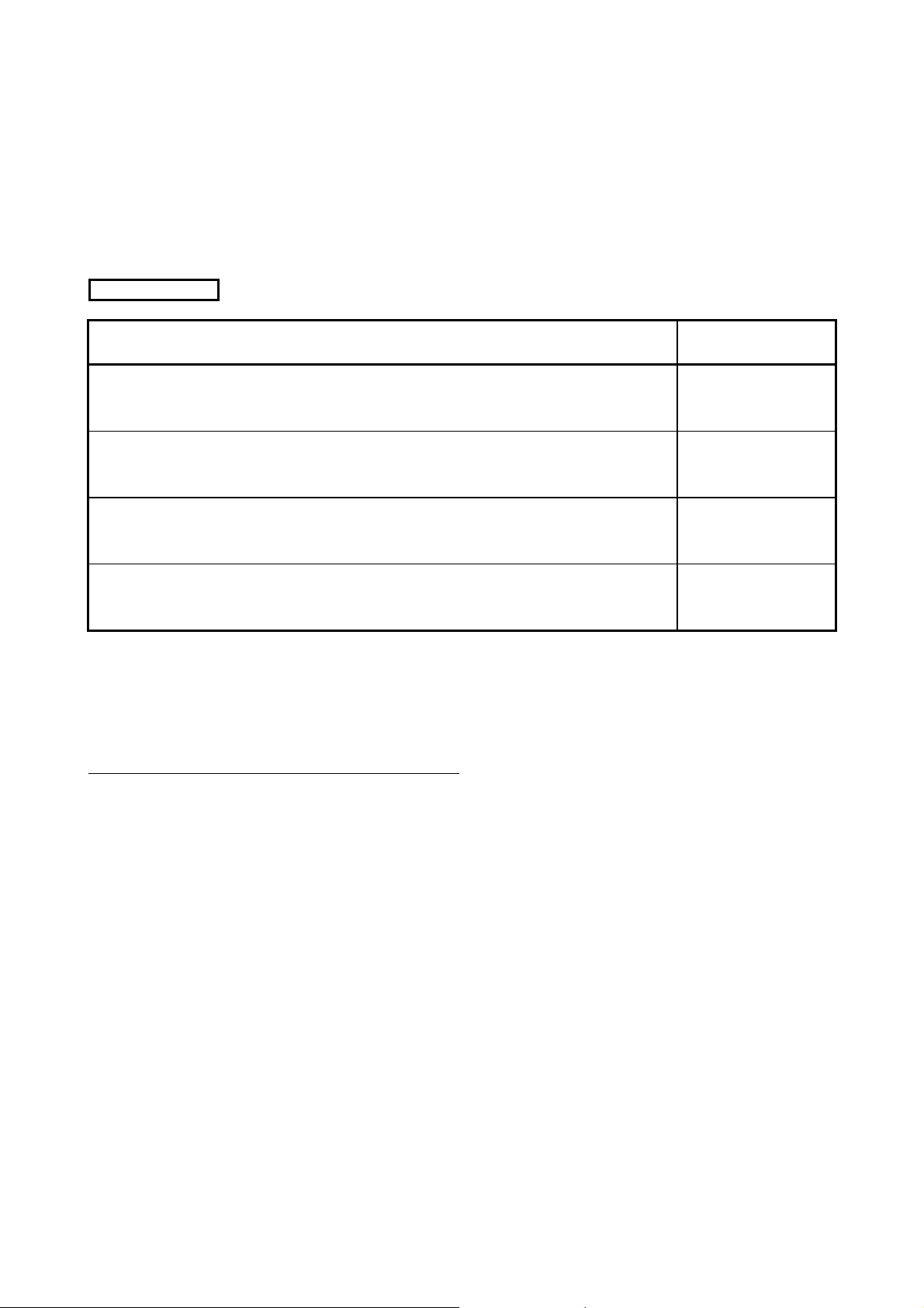
The following are manuals related to this product.
Request for the manuals as needed according to the chart below.
Related Manuals
Manual Name
Manual No.
(Type code)
CC-Link System Master/Local Module Type AJ61BT11/A1SJ61BT11 User's Manual
Describes the system configuration, performance specifications, functions, handling, wiring and
troubleshooting of the AJ61BT11 and A1SJ61BT11. (Optionally available)
CC-Link System Master/Local Module Type AJ61QBT11/A1SJ61QBT11 User's Manual
Describes the system configuration, performance specifications, functions, handling, wiring and
troubleshooting of the AJ61QBT11 and A1SJ61QBT11. (Optionally available)
CC-Link System Master/Local Module User's Manual
Describes the system configuration, performance specifications, functions, handling, wiring and
troubleshooting of the QJ61BT11N. (Optionally available)
MELSEC-L CC-Link System Master/Local Module User's Manual
Describes the system configuration, Performance specifications, functions, handling, wiring and
troubleshooting of the L26CPU-BT and LJ61BT11. (Optionally available)
Compliance with the EMC and Low Voltage Directives
(1) For programmable controller system
To configure a system meeting the requirements of the EMC and Low Voltage
Directives when incorporating the Mitsubishi programmable controller (EMC and
Low Voltage Directives compliant) into other machinery or equipment, refer to
the "EMC AND LOW VOLTAGE DIRECTIVES" chapter of the User's Manual for
the CPU module used.
The CE mark, indicating compliance with the EMC and Low Voltage Directives,
is printed on the rating plate of the programmable controller.
IB-66721
(13J872)
IB-66722
(13J873)
SH-080394E
(13JR64)
SH-080895ENG
(13JZ41)
(2) For the product
For the compliance of this product with the EMC and Low Voltage Directives,
refer to the "CC-Link module" section in the "EMC AND LOW VOLTAGE
DIRECTIVES" chapter of the User's Manual for the CPU module used.
A - 8
Page 11

MEMO
A - 9
Page 12

1. OVERVIEW MELSEC-A
1. OVERVIEW
1
1.1 Features
This user's manual describes the specification and handling of AJ65BT-64DAV digital analog voltage
conversion module (abbreviated as AJ65BT-64DAV from here on) and AJ65BT-64DAI digital analog
current conversion module (abbreviated as AJ65BT-64DAI from here on), which is used as the remote
device station for the CC-Link system.
(1) AJ65BT-64DAV
This is a module which converts the digital values (16-bit encoded binary value) set in the
programmable controller CPU to analog values (-10V to 0V to 10V voltage), and performs an
external output to four channels.
(2) AJ65BT-64DAI
This is a module which converts the digital values (16-bit encoded binary value) set in the
programmable controller CPU to analog values (4mA to 20mA current), and performs an external
output to four channels.
In this manual, the name which refers to both AJ65BT-64DAV and AJ65BT-64DAI is abbreviated as
“AJ65BT-64DAV/DAI.”
The AJ65BT-64DAV/DAI has the following features:
(1) One module can provide four channels of D/A conversion.
The AJ65BT-64DAV/DAI can produce output of analog values (voltage/current) to four external
devices.
(2) The analog-output enable/prohibit setting is possible for each channel.
The sequence program can specify whether to enable or prohibit analog output to the external
devices after the D/A conversion for each channel.
Analog output from the channel where the analog output is prohibited will be 0V or 0mA.
(3) You can make the analog output hold/clear setting at a programmable controller CPU stop or link
error occurrence (all channels batch).
Using the HOLD/CLR terminal, you can select whether to hold or clear the analog output at the
instant the programmable controller CPU is set to a STOP status or a link error occurs.
(4) Offset and gain setting
When a fine I/O conversion characteristic is required, the offset and gain setting of each channel
can be set without a volume control, enabling to modify the I/O conversion characteristic as
desired.
1-1
Page 13

1. OVERVIEW MELSEC-A
MEMO
1
1-2
Page 14

2. SYSTEM CONFIGURATION MELSEC-A
2. SYSTEM CONFIGURATION
2
(1) Applicable master modules
For available master modules, visit the CC-Link Partner Associations (CLPA) website at:
http://www.cc-link.org/
Remark
Check the specifications of the master module before use.
2-1
Page 15

2. SYSTEM CONFIGURATION MELSEC-A
MEMO
2
2-2
Page 16
3. SPECIFICATIONS MELSEC-A
3. SPECIFICATIONS
The general specifications, performance specifications, and I/O characteristics of the
AJ65BT-64DAV/DAI are explained.
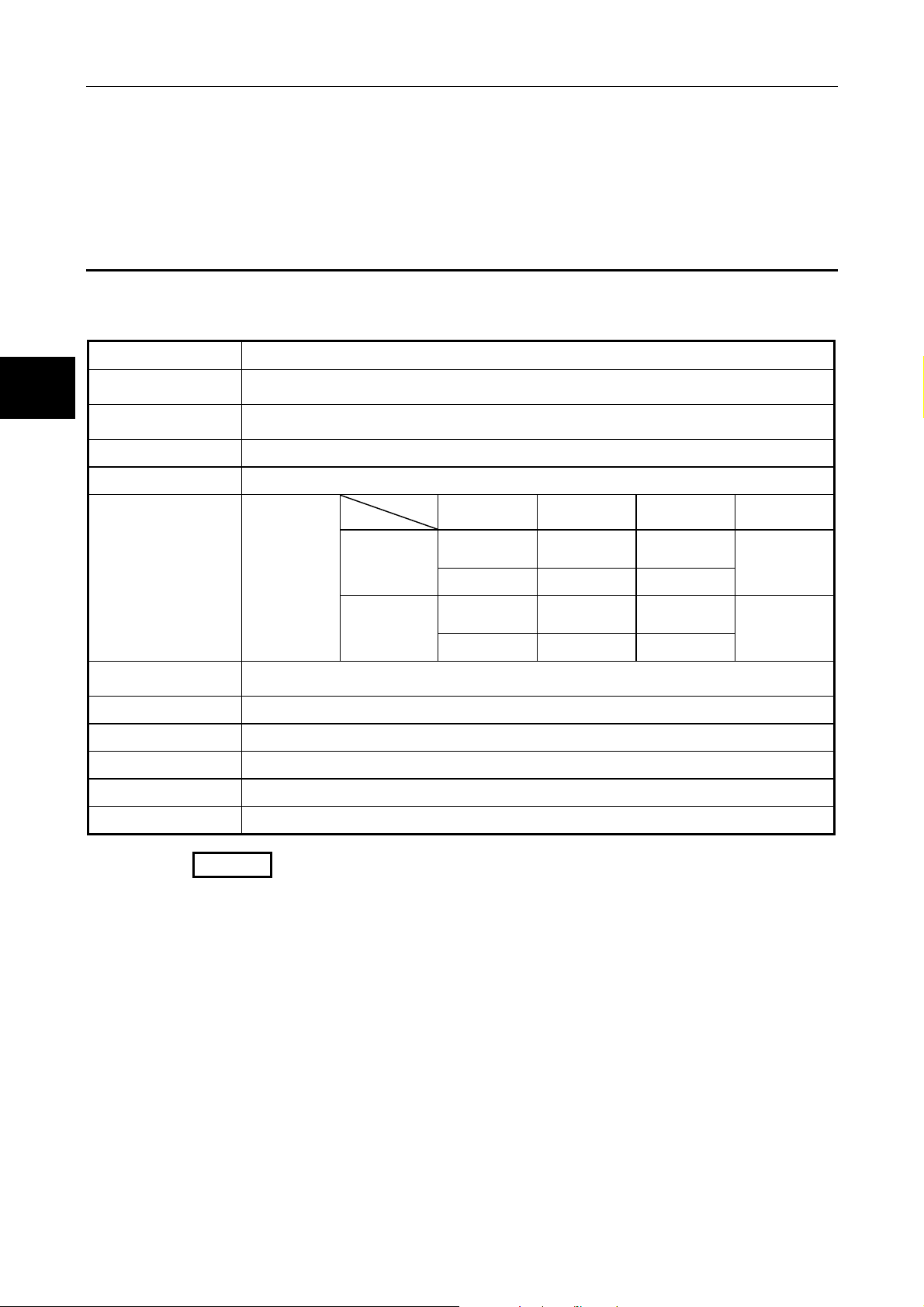
3.1 General Specification
3
Usage ambient
temperature
Storage ambient
temperature
Usage ambient humidity 10 to 90%RH, no condensation
Storage ambient humidity 10 to 90%RH, no condensation
Vibration durability
Shock durability
Usage environment No corrosive gas
Usage height *
Installation area Within the control board
The general specifications of the AJ65BT-64DAV/DAI are shown in Table 3.1.
Item Specification
Conforming to
JIS B 3502,
IEC 61131-2
1
Table 3.1 General specification
0 to 55°C
-20 to 75°C
Frequency Acceleration Amplitude
For intermittent
vibration
For continuous
vibration
5 to 9Hz —
2
9 to 150Hz 9.8m/s
5 to 9Hz —
9 to 150Hz 4.9m/s
Conforming to JIS B 3502, IEC 61131-2
2
(147m/s
, 3 times each in XYZ directions)
Less than 2000 m (Less than 6562 ft.)
—
2
—
3.5mm
(0.14 inches)
1.75mm
(0.069 inches)
Number of
sweeps
10 times in
each X, Y, and
Z direction
—
Over-voltage category *2 Less than II
Pollution rate *3 Less than 2
Remark
*1 Do not operate or store the programmable controller in the environment where the pressure
applied is equal to greater than the atmospheric pressure at the altitude of 0m.
Doing so may cause a malfunction. Please consult our branch office when the programmable
controller is to be operated under pressure.
*2 Indicates the location where the device is connected from the public cable network to the device
structure wiring area.
Category II applies to the devices to which the power is supplied from a fixed equipment.
Surge withstand voltage for devices with up to 300V of rated voltage is 2500V.
*3 This is an index which indicates the degree of conductive object generation in the environment
where the device is used. Level 2 is an environment where only nonconductive objects are
formed with some chances of temporary conductivity generation due to occasional condensation.
3-1
Page 17
3. SPECIFICATIONS MELSEC-A
3.2 Performance Specification
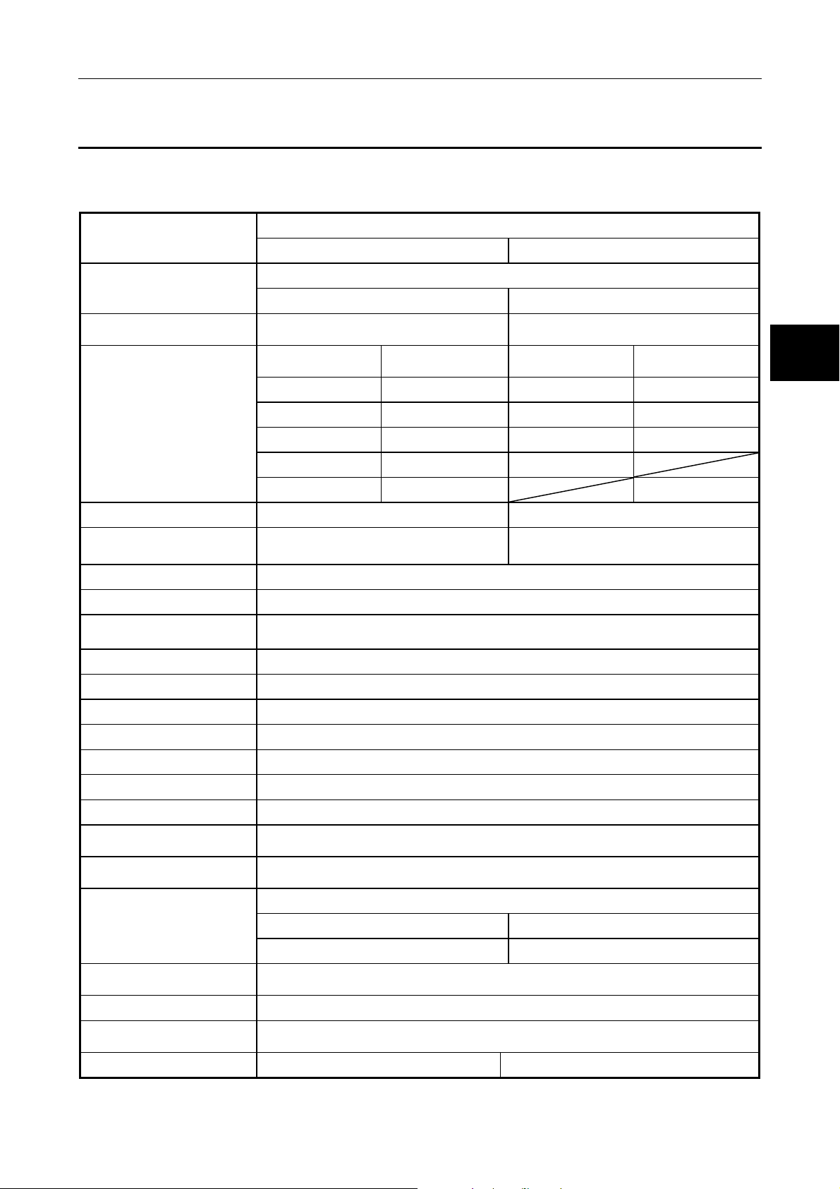
The performance specification of the AJ65BT-64DAV/DAI is shown Table 3.2:
Table 3.2 Performance specification
Item
Digital input value
Analog conversion value
I/O characteristics
Maximum resolution *1 5mV 4μA
Total accuracy *2
(accuracy for the maximum value)
Maximum conversion speed *3 Max. 1ms per channel (4ms per 4 channels)
Output short-circuit protection Yes
Insulation system
Analog output points 4 channels per module
(External load resistance: 2kΩ to 1MΩ)
Digital input value
AJ65BT-64DAV AJ65BT-64DAI
16-bit encoded binary (valid bit: 12 bits)
-2048 to 2047 0 to 4095
Voltage: -10 to 10VDC
Analog conversion
value
2000 10V 4000 20mA
1000 5V 2000 12mA
0 0V 0 4mA
-1000 -5V
-2000 -10V
± 1% (± 100mV) ± 1% (±200
Across output channels: Non-insulated
Across external supply power and analog output: Transformer insulated
Specification
Current: 4 to 20mADC
(External load resistance: 0 to 600Ω)
Digital input value
Analog conversion
value
μ
A)
3
Offset/gain adjustment Yes (user setting or factory setting)
CC-Link station type Remote device station
Number of occupied stations 2 stations
Connector terminal block 27-point terminal block (M3.5 × 7 screws)
Supported cable size 0.75 to 2.00mm2
Supported solderless terminal RAV 1.25-3.5 (according to JIS C 2805), RAV 2-3.5
Module installation screw
Supported DIN rail
External supply power
Current consumption:0.18A (at 24VDC) Current consumption:0.27A (at 24VDC)
Noise resistance
Dielectric withstand voltage Power and communication systems batch-Analog output batch, 500VAC, one minute
Insulation resistor
Weight 0.4kg 0.4kg
Measured using a noise simulator with 1μs of noise amplitude and 25 to 60Hz of noise frequency.
M4 x 0.7mm x 16mm or larger screw (tightening torque 0.78 to 1.18N⋅m)
Installable with the DIN rail.
TH35-7.5Fe, TH35-7.5Al,TH35-15Fe
(conforming to JIS C 2812)
24V DC (20.4V DC to 26.4V DC)
Inrush current: 1.5A, within 0.67ms Inrush current: 3.2A, within 0.43ms
Noise voltage: 500Vp-p
Power and communication systems batch-Analog output batch, 500VDC
10MΩ or more at the insulation resistance tester
3-2
Page 18
3. SPECIFICATIONS MELSEC-A
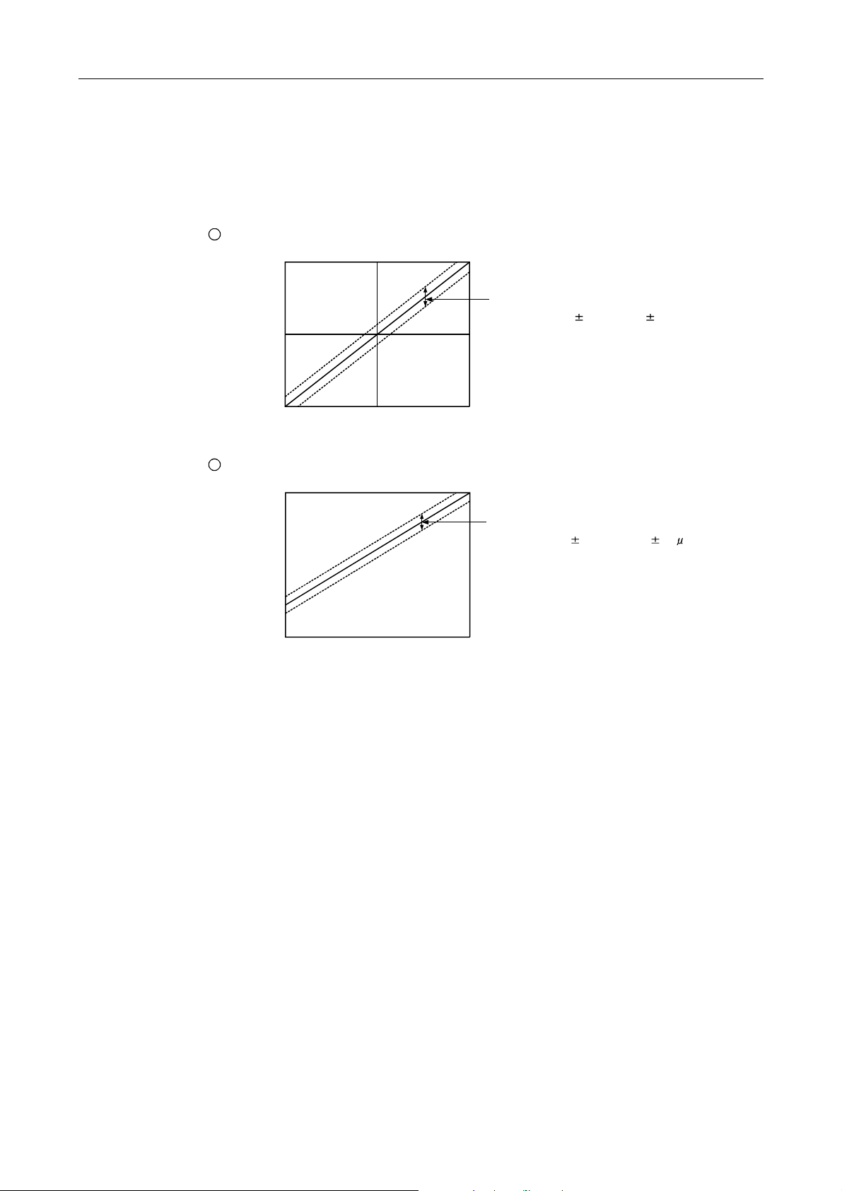
(
*1 Maximum resolution of analog value
The maximum resolution of analog value means the variation of analog value when the digital
value changes for "1".
*2 Total accuracy
The total accuracy is the accuracy of the maximum analog output value.
1
The overall accuracy of the AJ65BT-64 DAV is the accuracy for 10V.
+10V
e
u
l
a
v
t
u
p
t
0V
u
o
g
o
l
a
n
A
-10V
-2000 20000
Digital input value
Depending on the operating environment
the ambient temperature, noise), it fluctuates
within a range of 1.0% of 10V ( 100mV).
2
The overall accuracy of the AJ65BT-64 DAI is the accuracy for 20mA.
20mA
e
u
l
a
v
t
u
p
t
u
o
g
o
l
a
n
4mA
A
0mA
0 4000
Digital input value
Depending on the operating environment
(the ambient temperature, noise), it fluctuates
within a range of 1.0% of 20mA ( 200 A).
*3 Maximum conversion speed
The maximum conversion speed means the time required to read the digital value written in the
buffer memory, execute the D/A conversion, and output the specified analog value. It takes the
longest (1ms) to produce the maximum analog output value when the current output is the
minimum, and to produce the minimum analog output value when the current output is the
maximum.
3-3
Page 19
3. SPECIFICATIONS MELSEC-A
A
3.3 I/O Conversion Characteristics
The I/O conversion characteristics of the AJ65BT-64DAV/DAI are explained.
3.3.1 Offset value and gain value
(1) Offset value
This is an analog value (voltage or current value) produced by the AJ65BT-64DAV/DAI when the
digital value set by the programmable controller CPU is "0".
(2) Gain value
This is an analog value (voltage or current value) produced by the AJ65BT-64DAV/DAI when the
digital value set by the programmable controller CPU is "2000" for AJ65BT-64DAV, and "4000"
for AJ65BT-64DAI.
(3) The factory-set offset and gain values are as follows:
AJ65BT-64DAV AJ65BT-64DAI
Offset value 0V 4mA
Gain value 10V 20mA
(4) The offset value and gain value can be set separately for each channel in the test mode.
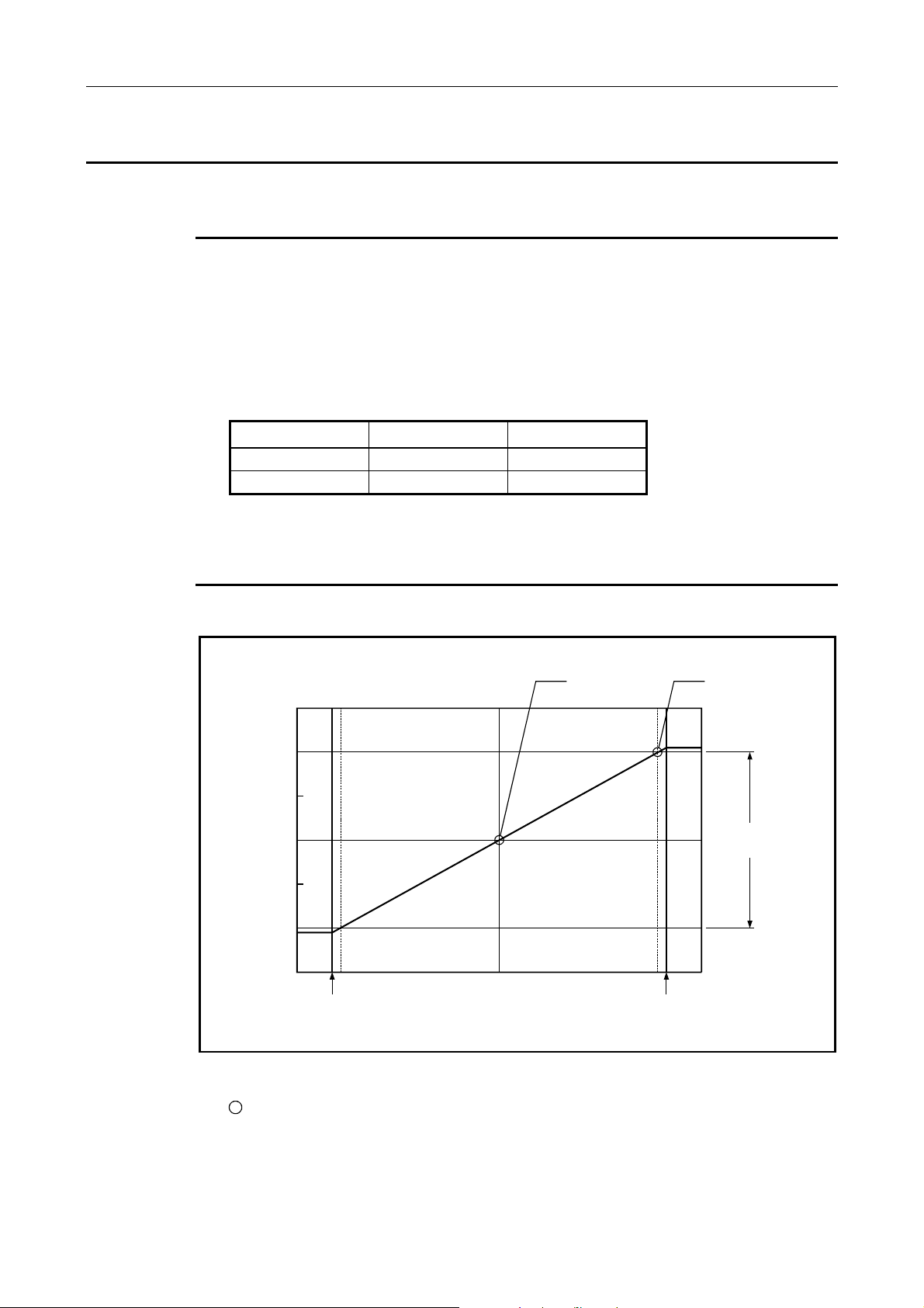
3.3.2 I/O conversion characteristics
(1) When AJ65BT-64DAV is used:
(V)
15
10
e
5
g
a
t
l
o
v
t
u
0
p
t
u
o
g
o
l
a
-5
n
A
-10
-15
-2000
-2048
0
Digital input value
Offset value Gain value
nalog output
practical range
2000
2047
Figure 3.1 I/O conversion characteristics of the AJ65BT-64DAV
1
How to calculate the analog output value:
The resolution of AJ65BT-64DAV can be set arbitrarily by modifying the settings of the offset
value and gain value.
How to calculate the analog value resolution and the analog output value for a given digital
input value when the settings of the offset value and gain value are changed is shown next.
3-4
Page 20

3. SPECIFICATIONS MELSEC-A
The I/O conversion characteristics are shown in
the graph on the right when the offset value and
the gain value are set as in the following table:
Number Offset value Gain value
(Analog output) = (Analog resolution) × (Digital input value) + (Offset value)
(Analog resolution) =
(Gain value) - (Offset value)
2000
2
The following graph shows the I/O characteristics when the offset and gain values of the
AJ65BT-64DAV are changed:
1
0V 10V
2
-10V 10V
3
4V 8V
Example
The analog output voltage for the characteristic graphs 1 to 3 becomes as below, when the digital
input value is at 1000 and 500:
Number Digital input value Analog output voltage
1
2
3
1000 5.0V
500 2.5V
1000 0V
500 -5.0V
1000 6.0V
500 5.0V
Figure 3.2 I/O conversion characteristics of AJ65BT-64DAV
3-5
Page 21

3. SPECIFICATIONS MELSEC-A
(2) When AJ65BT-64DAI is used:
(mA)
20
t
n
15
e
r
r
u
c
t
u
10
p
t
u
o
g
o
l
5
a
n
A
0
0 4000
Figure 3.3 I/O conversion characteristics of AJ65BT-64DAI
1
How to calculate the analog value
The resolution of AJ65BT-64DAI can be set arbitrarily by modifying the settings of the offset
value and gain value.
How to calculate the analog value resolution and the analog output value for a given digital
input value when the settings of the offset value and gain value are changed is shown.
(Analog output) = (Analog resolution) × (Digital input value) + (Offset value)
(Analog resolution) =
Offset value
Digital input value
(Gain value) - (Offset value)
4000
4095
Gain value
Analog output
practical range
3-6
Page 22

3. SPECIFICATIONS MELSEC-A
2
The following graph shows the I/O characteristic when the offset and gain values of the
AJ65BT-64DAI are changed:
The I/O conversion characteristics are shown in
the graph on the right when the offset value and
the gain value are set as in the following table:
Number Offset value Gain value
1
10mA 20mA
2
4mA 20mA
3
6mA 16mA
(mA)
t
n
e
r
r
u
c
t
u
p
t
u
o
g
o
l
a
n
A
20
15
10
Analog
output
practical
5
0
range
0
Digital input value
Example
The analog output voltage for the characteristic graphs 1 to 3 becomes as below, when the digital
input value is at 2000 and 1000:
Number Digital input value Analog output voltage
1
2
3
2000 15mA
1000 12.5mA
2000 12mA
1000 8mA
2000 11mA
1000 8.5mA
Figure 3.4 I/O conversion characteristics of AJ65BT-64DAI
4000
4095
3-7
Page 23

3. SPECIFICATIONS MELSEC-A
3.4 Various Functions to Control the Analog Output
Various functions to control the analog output of the AJ65BT-64DAV/DAI are explained.
3.4.1 Function to specify hold or clear of the analog output when the
programmable controller CPU is in the STOP status (HOLD/CLEAR
setting)
Using this function, the HLD/CLR terminal on the module front panel can be used to set whether to
retain or clear (i.e. to output the offset) the analog output value immediately before the programmable
controller CPU enters the STOP status or before the AJ65BT-64DAV/DAI stops the D/A conversion
due to an error. All channels are set simultaneously. (Including a time when link communications are
shut off)
3.4.2 Function to specify executing or not executing the D/A conversion processing (Analog output enable/disable flag)
Using this function, whether to output the D/A conversion value or the offset value can be selected for
each channel by turning on or off the Analog output enable/disable flag from the programmable
controller program.
However, the D/A conversion time (conversion speed) is constant regardless of the setting of the
Analog output enable/disable flag.
ON: D/A conversion value OFF: Offset value
3.4.3 Function to specify enabling or prohibiting of the analog value external output (Analog output enable/prohibit setting)
Using this function, whether to enable or prohibit the external output of the analog signal can be
specified for each channel by writing "0" or "1" to the remote register's address from the
programmable controller program.
1: 0V/0mA 0: D/A conversion value or offset value
3.4.4 Offset/gain setting
When a fine I/O conversion characteristic is required, the I/O conversion characteristics can be
modified arbitrarily by setting the offset and gain of each channel without a volume control, after
entering the test mode by short-circuiting the test mode terminal. When it is not necessary, turning
on the RYn4, which is the I/O signal to the master station, selects the factory-configured offset and
gain values.
Factory-configured values:
AJ65BT-64DAV........ Offset value 0V, Gain value 10V
AJ65BT-64DAI ......... Offset value 4mA, Gain value 20mA
3.4.5 Combinations of various functions
By combining the functions explained above, the analog output when the programmable controller
CPU is in the RUN status and when a module error occurs can be set as desired, as shown in Table
3.3.
Select each function depending on the analog output status of your choice.
3-8
Page 24

3. SPECIFICATIONS MELSEC-A
Table 3.3 Analog output status combination list
Setting
combination
Execution
status
Analog output status when the programmable
controller CPU is in the RUN status
Analog output status when the programmable
controller CPU is in the STOP status
Analog output status when the programmable
controller CPU is in the error status
Analog output status when an error has
occurred in the AJ65BT-64DAV/DAI
Analog output status when a WDT error (*)
has occurred in the AJ65BT-64DAV/DAI
Analog output status when the L.RUN LED is
turned off (when link communications are
shut off)
Analog output status after reset
HOLD/CLEAR setting CLEAR HOLD
Analog output enable
signal
Analog output
enable/disable flag
(*) WDT error ...........indicates the abnormal operation time by the programmable controller. The
Enable (on) Prohibit (off) Enable (on)/Prohibit (off)
Enable (0) Prohibit (1) Enable (0) Prohibit (1) Enable (0) Prohibit (1)
Output of the
analog value
after D/A
conversion
from the digital
value specified
by the
programmable
controller CPU
Offset value 0V/0mA
Offset value 0V/0mA
Output of the
maximum or
minimum
analog value
Offset value 0V/0mA
Output of the
analog value
after D/A
conversion
from the digital
value specified
by the
programmable
controller CPU
0V/0mA
0V/0mA
0V/0mA
Offset
value
Offset
value
Offset
value
Offset
value
Offset
value
Offset
value
0V/0mA
0V/0mA
0V/0mA
0V/0mA
0V/0mA
0V/0mA
0V/0mA
Output of the
analog value
after D/A
conversion
from the
digital value
specified by
the
programmable
controller CPU
Analog value
before the
programmable
controller CPU
stop is
retained.
Analog value
before the
CPU error is
retained.
Output of the
maximum or
minimum
analog value
Analog value
before the
LINK ERR is
retained.
Output of the
analog value
after D/A
conversion
from the
digital value
specified by
the
programmable
controller CPU
0V/0mA
0V/0mA
0V/0mA
0V/0mA
0V/0mA
0V/0mA
elapsed time for one scan by the program is monitored, and a WDT error results
when it does not finish within the scheduled time.
3-9
Page 25

3. SPECIFICATIONS MELSEC-A
3.5 I/O Signals to the Master Station
Assignment of the I/O signals and function of each signal are explained.
3.5.1 I/O signal list
The AJ65BT-64DAV/DAI uses 32 input points and 32 output points for exchanging signals with the
master station.*1 The allocation of the I/O signals and the name of each signal are listed in Table 3.4.
An RX device indicates an input signal from the AJ65BT-64DAV/DAI to the master module, and a RY
device indicates an output signal from the master module to the AJ65BT-64DAV/DAI.
Table 3.4 I/O signals
Signal direction:
AJ65BT-64DAV/DAI→Master
Device No. Signal name Device No. Signal name
RXn0 RYn0
RYn1
to
RXnF
RX (n+1) 0
to
RX (n+1) 7
RX (n+1) 8
RX (n+1) 9 Initial data setting complete flag RY (n+1) 9 Initial data setting request flag
RX (n+1) A Error status flag RY (n+1) A Error reset request flag
RX (n+1) B Remote READY
RX (n+1) C
to
RX (n+3) F
Initial data processing request
Unusable
Unusable
flag
Unusable
n: The address allocated to the master station in the station number setting
RYn2
RYn3
RYn4 Offset/gain value selection
RYn5
to
RYnF
RY (n+1) 0
to
RY (n+1) 7
RY (n+1) 8
RY (n+1) B
to
RY (n+3) F
Signal direction:
Master→AJ65BT-64DAV/DAI
CH.1 Analog output
enable/disable flag
CH.2 Analog output
enable/disable flag
CH.3 Analog output
enable/disable flag
CH.4 Analog output
enable/disable flag
Unusable
Unusable
Initial data processing complete
flag
Unusable
*1 Although the number of occupied stations for the AJ65BT-64DAV/DAI is
2, inputs, RX(n+2) 0 to RX(n+3)F, are not used.
However, devices for inputs, RX(n+2) 0 to RX(n+3)F, and outputs,
RY(n+2) 0 to RY(n+3) F, are reserved in the master module or CPU
module. When creating a program, pay attention to device allocation.
Point
If a device not allowed to use is turned on/off from the sequence program, the function of the
AJ65BT-64DAV/DAI is not guaranteed.
3-10
Page 26

3. SPECIFICATIONS MELSEC-A
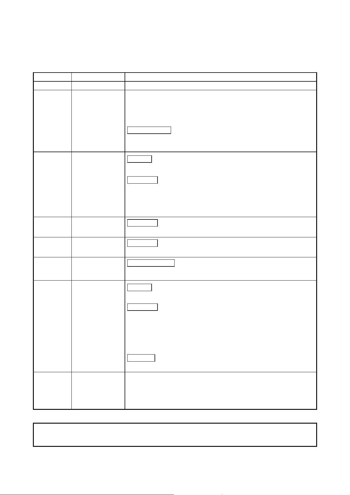
3.5.2 Functions of the I/O signals
Functions of the I/O signals of the AJ65BT-64DAV/DAI are shown in Table 3.5.
Table 3.5 Descriptions of the I/O signals
Device number Signal Name Description
RX (n+1) 8
RX (n+1) 9
RX (n+1) A Error status flag
RX (n+1) B Remote READY
RYn0
to
RYn3
RYn4
RY (n+1) 8
RY (n+1) 9
RY (n+1) A
Initial data
processing request
flag
Initial data setting
complete flag
CH.
analog output
enable/disable flag
Offset/gain value
selection
Initial data
processing complete
flag
Initial data
processing request
flag
Error reset request
flag
The ON and OFF timing of each flag for the initial data processing request, processing complete,
setting complete, and the setting request by the AJ65BT-64DAV/DAI:
After the power is turned on or after the hardware reset, the initial data
processing request flag is turned on by the AJ65BT-64DAV/DAI in order to
request the initial data setting. It is turned off when the initial data setting
is complete (i.e. initial data processing complete flag RY(n+1)8 is turned
on).
When there is an initial data setting request (i.e. RY(n+1)9 is turned on), it
is turned on by the initial data setting completion. When the initial data
setting request flag is turned off after the initial data setting completion, the
initial data setting complete flag is also turned off.
This is turned on when an error other than the WDT error occurs on the
AJ65BT-64DAV/DAI.
This is turned on when the initial data setting is complete and the
AJ65BT-64DAV/DAI is in the READY status, after the power is turned on or
after the hardware reset. It is turned off during the test mode.
(This is used to interlock the read and write from the master module.)
These are the analog value output enable signals for channels 1 through 4.
The analog output value from the corresponding channel is enabled when
turned on.
Turn it off to prohibit the output of the analog value.
"User settings" or "factory settings" of the offset and gain values are
selected by switching the RYn4. To select the factory setting, keep the
RYn4 set to on.
After the power is turned on or after the hardware reset, the initial data
processing is executed by the initial data processing request, and this flag
is turned on after the processing is completed.
Turn this on to set or modify the initial data.
When the error reset request flag (RY(n+1)A) is turned on, the error status
flag (RX(n+1)A) is turned off and the error code of the remote register write
area is cleared (0000
H).
3-11
Page 27

3. SPECIFICATIONS MELSEC-A
3.6 Remote Register
The AJ65BT-64DAV/DAI has a remote register (does not have backup) for data communication with
the master module. The remote register allocation and data structure are described below.
3.6.1 Allocation of the remote register
The allocation of the remote register is shown in Table 3.6.
Table 3.6 Allocation of the remote register
Write area
Read area
(M→R)
(R→M)
Address Description Initial value
RWwm CH.1 digital value setting 0
RWwm+1 CH.2 digital value setting 0
RWwm+2 CH.3 digital value setting 0
RWwm+3 CH.4 digital value setting 0
RWwm+4
RWwm+5
RWwm+6
RWwm+7
RWrn CH.1 set value check code 0
RWrn+1 CH.2 set value check code 0
RWrn+2 CH.3 set value check code 0
RWrn+3 CH.4 set value check code 0
RWrn+4 Error code 0 Section 3.6.5
RWrn+5
RWrn+6
RWrn+7
m, n: The address set for the master station in the station number setting.
Analog output enable/disable
setting
Unusable
Unusable
0 Section 3.6.3
Reference
section
Section 3.6.2
Section 3.6.4
Point
Do not execute read or write to the remote register that is not allowed to use. When a read or
write is executed, the function of the AJ65BT-64DAV/DAI is not guaranteed.
3-12
Page 28

3. SPECIFICATIONS MELSEC-A
3.6.2 Digital value setting area for channels 1 through 4
(1) This area is used to write the digital value for the D/A conversion from the programmable
controller CPU.
(2) The digital values at all channels become "0" in the following conditions:
(a) After the power is turned on, when the remote READY (RX(n+1)B) is turned on.
(b) After the reset of the programmable controller CPU, when the remote READY (RX(n+1)B) is
turned on.
(3) The digital value can be set as 16-bit signed binary data and within the available setting range of
the digital value resolution.
If a value beyond the range of the digital value resolution is set, the data in Table 3.7 is applied
for the D/A conversion.
In addition, the checking code is stored in the set value checking code storage area (addresses
from RWrn to RWrn+3).
Table 3.7 Available setting range of the digital value
Digital value for the D/A conversion
when the value beyond the range is set
2048 or higher: 2047
-2049 or lower: -2048
4096 or higher: 4095
-1 or lower: 0
AJ65BT-64DAV
AJ65BT-64DAI
Model Name Available setting range
-2048 to 2047
(Practical range: -2000 to 2000)
0 to 4095
(Practical range: 0 to 4000)
3.6.3 Analog output enable/prohibit channel
(1) Enable or prohibit of the external output of the analog value from each channel is set in this area.
(2) Output is prohibited at all channels in the following conditions:
(a) When the power is turned on.
(b) When the power is reset.
Note that when initial data processing is finished, (module ready turns on, and) the output is
enabled at all channels with the default values of 0.
(3) Enable/prohibit of the external output is set to 0 or 1 for each channel.
(a) 0 ............ Enabled
(b) 1 ............ Prohibited
(4) Configuration of the output enable/prohibit area for each channel is as follows:
3-13
Page 29

3. SPECIFICATIONS MELSEC-A
3.6.4 Set value checking code storage area for channels 1 through 4
This area is used to check if the digital value is within or out of the setting range. One of the following
checking codes is stored when the digital value lower or higher than the setting range is set.
Check code list
Check code Description
000FH A digital value which exceeds the setting range was set.
00F0H A digital value which is below the setting range was set.
Both a digital value below the setting range and digital value exceeding the setting
range were set.
00FFH
(1) The check code once stored is not reset even if the set value is set to within the valid setting
allowed range.
(2) The storage area or the set value check code is reset by turning on the error reset request flag
(RY (n+1) A).
3.6.5 Error code
For example, the 00FF
range is written, and then, without the check code being reset, a digital value that
falls short of the valid range is written.
H check code is stored if a digital value exceeding the valid
(1) If an error occurs when starting the module or writing data to the AJ65BT-64DAV/DAI (the RUN
LED flashes), the following error code is stored in the error code (RWrn+4) in the
AJ65BT-64DAV/DAI remote register.
Error code list
Error code Error description Processing
The set digital value is outside the
11
999
(2) When multiple errors occurred, the error code of the first error is stored, but the other errors are
not stored.
(3) The error code reset is performed by turning on the error reset request flag (RY (n+1) A).
When the error code is “999”, however, it cannot be reset because the hardware of the module is
faulty.
setting range.
The
indicates the channel number
where the error occurred.
The offset/gain setting values stored in
2
PROM became faulty.
E
The indicates the channel number where the error occurred.
Correct the digital value to within the setting
range.
Power-cycle the AJ65BT-64DAV/DAI again.
If this recurs, the module may be faulty.
Consult your local servicing company, dealer
or our branch office.
3-14
Page 30

4. SETUP AND PREPARATION BEFORE OPERATION MELSEC-A
4. SETUP AND PREPARATION BEFORE
4.1 Precautions When Handling
4
OPERATION
The precautions when handling the AJ65BT-64DAV/DAI are described below:
CAUTION
z Do not touch any terminal while power is on.
Doing so may cause malfunction.
z Be sure there are no foreign substances such as sawdust or wiring debris inside the module.
Such debris could cause fires, damage, or erroneous operation.
z Do not disassemble or modify the modules.
Doing so may cause failure, malfunction, injury, or a fire.
z Do not directly touch the module's conductive parts or electronic components.
Touching the conductive parts could cause an operation failure or give damage to the module.
z Do not drop or apply strong shock to the module.
Doing so may damage the module.
z Do not remove the module print board from the case.
This may cause breakdowns.
z Tighten the terminal screws with the specified torque.
If the terminal screws are loose, it could result in short circuits, fire, or erroneous operation.
z When disposing of this product, treat it as industrial waste.
z If the terminal screws are loose, it could result in short circuits, fire, or erroneous operation.
Using this programmable controller in an environment outside the range of the general
specifications could result in electric shock, fire, erroneous operation, and damage to or
deterioration of the product.
z For protection of the switches, do not remove the cushioning material before installation.
z Securely fix the module with a DIN rail or mounting screws. Tighten the screws within the
specified torque range.
Undertightening can cause drop of the screw, short circuit, or malfunction.
Overtightening can damage the screw and/or module, resulting in drop, short circuit, or
malfunction.
z Be sure to shut off all phases of the external power supply used by the system before mounting
or dismounting the module to or from the panel.
Not doing so could result in damage to the product.
z Before touching the module, always touch grounded metal, etc. to discharge static electricity
from human body.
Failure to do so can cause the module to fail or malfunction.
(1) Tighten the screws such as module installation screws with the following torque :
Module installation screw (M4 screw) 0.78 to 1.18 N·m
Terminal block terminal screw (M3.5 screw) 0.59 to 0.88 N·m
Terminal block installation screw (M4 screw) 0.78 to 1.18 N·m
(2) When using the DIN rail adapter, install the DIN rail by making sure of the following:
(a) Applicable DIN rail models (conforming to JIS C 2812)
TH35-7.5Fe
TH35-7.5Al
TH35-15Fe
(b) DIN rail installation screw interval
(3) Refer to the Master Module user's manual for the name, specification, and manufacturers of
When installing the DIN rail, tighten the screws with less than 200mm (7.87 inch) pitches.
supported cables for the use with AJ65BT-64DAV/DAI.
Screw location Tightening torque range
4-1
Page 31

4. SETUP AND PREPARATION BEFORE OPERATION MELSEC-A
4.2 Name of Each Part
The name of each part in the AJ65BT-64DAV/DAI is described.
MITSUBISHI
MELSEC
AJ65BT-64DA
PW
RUN
L RUN
L ERR.
SD
RD
STATION NO.B RATE
X10 X1
0
0
OFFSET
GAIN
1
9
2
8
3
7
456
GAIN. RESET
SET
DOWN
0
1
2
3
456
1
2
3
4
CH.
1
2
3
4
Number Name Description
1
Station number
setting switch
2
B RATE (Transfer
baud rate) setup
switch
↓ ×10 The AJ65BT-64DAV/DAI station number
↓ ×1 is set within the range 1 to 63. (Factory shipment setting : 00)
Setting number Transfer baud rate
0 156kbps(Factory shipment setting)
1 625kbps
2 2.5Mbps
3 5Mbps
4 10Mbps
4
Unused (When a value other than 0 to 4 is set, L ERR. LED turns on, and results in a
communication error.)
3
CH. (CHANNEL)
selection switch
4
OFFSET/GAIN
(Offset/gain)
setting switch
Select the channel to perform offset adjustment or gain adjustment.
(Positions other than 1 to 4 are not processed.)
The switch to set the offset/gain values during test mode.
(1) OFFSET position : Calibration mode for the offset value
(2) GAIN position : Calibration mode for gain value
(3) SET position : When the switch is set from the OFFSET/GAIN position,
which are modes to record offset/gain value to the SET
position, to the SET position, the offset/gain value is
recorded.
5
UP/DOWN switch The switch to adjust the analog output value for the offset/gain of the specified
channel. The analog output value increases/decreases by turning on the UP/DOWN
switch.
6
RESET switch Resets the H/W.
Initializes the AJ65-BT-64DAV/DAI I/O signals, remote register, and operation
processing. When the switch is turned on, AJ65BT-64DAV/DAI initial data
processing request flag turns on.
4-2
Page 32

4. SETUP AND PREPARATION BEFORE OPERATION MELSEC-A
Number Name Description
7
Operation status
display LED
8
Terminal block
PW LED On : When the power is on
Off : When the power is shut off
RUN LED
Normal
mode
On : Normal operation
Flashing : W rite data error
Off : 24VDC power shutoff or watchdog
timer error
Test mode Flashing : Flashes in 0.5 second intervals
when the offset/gain setting switch
is at OFFSET or GAIN. Flashes in
0.1 second intervals when
exceeding the upper or lower limits
of the allowable setting using the
UP/DOWN switch.
Off : W hen the offset/gain setting switch
is at SET.
L RUN LED On : Normal communication
Off : Communication interrupted (timeout error)
SD LED On : Data being transferred
RD LED On : Data being received
L ERR. LED On : When the baud rate or the station number
setting is out of range.
Flashing at regular intervals :
When the baud rate or station number setting is
changed after power-on or reset.
Flashing at irregular intervals :
When you forgot fitting the termination resistors
or the module or CC-Link dedicated cable is
affected by noise.
Off : Normal communication
AJ65BT-64DAV
1 3 5 7 9 111315171921232527
DA DG
2 4 6 8 10 12 14 16 18 2 0 22 24 26
+24V 24G
+24V 24G
DB SLD (FG) TEST TEST
HLD/
CLR
HLD/
CLR
CH1/
V+
COM COM COM COM
COM COM COM COM
CH2
V+
CH3
V+
CH4
V+
AJ65BT-64DAI
1 3 5 7 9 111315171921232527
DA DG
2 4 6 8 10 12 14 16 18 20 22 24 26
+24V 24G
+24V 24G
DB SLD (FG) TEST TEST
HLD/
CLR
HLD/
CLR
CH1/
I+
COM COM COM COM
COM COM COM COM
CH2
I+
CH3
I+
CH4
HLD/CLR setting terminal
....HOLD is set by shorting between terminals, and CLEAR is set by releasing.
Test mode setting terminal
....By shorting between terminals, the system enters the test mode
I+
4-3
Page 33

4. SETUP AND PREPARATION BEFORE OPERATION MELSEC-A
4.3 Offset/Gain Setting
When changing the I/O conversion characteristics, follow the procedure below.
4-4
Page 34

4. SETUP AND PREPARATION BEFORE OPERATION MELSEC-A
Point
(1) Set the offset and gain values in the actual usage state.
(2) The offset and gain values are stored in the AJ65BT-64DAV/DAI, and are not erased even
the power supply is shut off.
(3) Perform the offset/gain setting when the programmable controller CPU is stopped. When in
the test mode, D/A conversion is stopped for all channels, so use the remote READY signals
as an interlock.
(4) Perform the offset/gain setting in the range from DC -10 to +10V or from 4 to +20mA. When
the setting exceeds this range, the maximum resolution or total precision may not be in the
range indicated in the performance specification.
4.4 Station Number Setting
By the AJ65BT-64DAV/DAI station number setting, the addresses to store the control I/O signal data
and read/write data are determined.
For details, refer to the user's manual of the master module used.
4.5 Facing Direction of the Module Installation
Panel
M
I
T
S
U
B
I
S
H
I
M
I
T
S
U
B
I
S
H
I
I
H
S
I
B
U
S
T
I
M
When the module is installed next to the panel When the module is installed on the panel
4-5
Page 35

4. SETUP AND PREPARATION BEFORE OPERATION MELSEC-A
4.6 Data link Cable Wiring
The wiring of the CC-Link dedicated cable which connects the AJ65BT-64DAV/DAI and the master
module is described.
4.6.1 CC-Link dedicated cable connections
The CC-Link dedicated cable connections between the AJ65BT-64DAV/DAI and master module are as
follows:
4-6
Page 36

4. SETUP AND PREPARATION BEFORE OPERATION MELSEC-A
4.7 Wiring
Precautions when wiring the AJ65BT-64DAV/DAI and how to wire to the external devices are
explained.
4.7.1 Precautions when wiring
To obtain maximum performance from the functions of AJ65BT-64DAV/DAI and improve the system
reliability, an external wiring with high durability against noise is required.
The precautions performing external wiring for the AJ65BT-64DAV/DAI are shown below:
(1) Use separate cables for the AC and AJ65BT-64DAV/DAI external input signals, in order not to be
affected by the AC side surge or conductivity.
(2) Do not bunch the control wires or load cables from other than the programmable controller with
the wires to the module, or install them close to each other. Doing this makes the wiring easy to
accept the noise, surge or induction effects.
(3) Perform a one-point grounding for the shielded line or the shield of the shielded cable.
4.7.2 Wiring between the AJ65BT-64DAV/DAI and external devices
(1) Wiring example of the AJ65BT-64DAV and external devices is shown in Figure 4.1.
*1 Use a two-core twist shielded line for the wiring.
*2 When noise or ripple generates within the external wiring, connect a condenser with about
0.1 to 0.47μF (25V or higher voltage-resistant product) to the input terminal of the external
device.
Figure 4.1 Wiring example of the AJ65BT-64DAV and external devices
4-7
Page 37

4. SETUP AND PREPARATION BEFORE OPERATION MELSEC-A
(2) Wiring example of the AJ65BT-64DAI and external devices is shown in Figure 4.2.
*1 Use a two-core twist shielded line for the wiring.
*2 When noise or ripple generates within the external wiring, connect a condenser with about
0.1 to 0.47μF (25V or higher voltage-resistant product) to the input terminal of the external
device.
Figure 4.2 Wiring example of the AJ65BT-64DAI and external devices
Remark
Though you can perform the jumper wiring of the common line on the external device side, the
commons are connected also inside this module.
When wiring, be careful of sneak currents on the external device side.
4-8
Page 38

5. PROGRAMMING MELSEC-A
5. PROGRAMMING
The programming procedure, basic read/write programs, and program examples for the
AJ65BT-64DAV/DAI are described.
When applying any of the program examples introduced in this chapter to the actual system, verify the
applicability and confirm that no problems will occur in the system control.
Refer to the user's manual of the master module used for the master module, to Section 3.6 for the
remote registers, and to the AnSHCPU/AnACPU/AnUCPU/QCPU (A mode) Programming Manual
(Dedicated Instructions) for details of the dedicated instructions.
5.1 Programming Procedure
Create programs for executing the digital-analog conversion of the AJ65BT-64DAV/DAI in the
following procedure.
5
*1 When using the QCPU (Q mode), you can use the remote device station initialization procedure
*2 The remote device station initialization procedure registration function cannot be used to make
registration function to make settings. When using the ACPU, QCPU (A mode) or QnACPU, use
the sequence program to make settings.
settings.
Use the sequence program to make settings.
5-1
Page 39

5. PROGRAMMING MELSEC-A
5.2 Conditions of Program Example
The program examples in this chapter are created under the following conditions.
(1) System configuration
(2) Relationships between programmable controller CPU, master module and AJ65BT-64DAV
5
5-2
Page 40

5. PROGRAMMING MELSEC-A
POINT
Some CPU modules may not accept the devices used in the program example in this
chapter. For the setting ranges of the devices, refer to the user's manual of the CPU
module used.
For the A1SHCPU, for example, devices X100, Y100 and later are unusable. Use such
devices as B and M.
(3) Initial settings
Setting Item Settings
Offset/gain value selection Factory setting
Analog output enable/disable setting (RWw4) Channels 1, 2, 3, 4: enable
(4) Other settings
Setting Item Settings
CH.1 digital value setting (RWw0) 50
CH.2 digital value setting (RWw1) 100
CH.3 digital value setting (RWw2) 200
CH.4 digital value setting (RWw3) 3000
CH.1 analog output enable/disable flag (RY00) Enable
CH.2 analog output enable/disable flag (RY01) Enable
CH.3 analog output enable/disable flag (RY02) Enable
CH.4 analog output enable/disable flag (RY03) Enable
5-3
Page 41

5. PROGRAMMING MELSEC-A
5.3 Program Example for Use of the QCPU (Q mode)
The program examples in this section are created under the following conditions.
GX Developer is used to set the network and automatic refresh parameters.
Using the remote device station initialization procedure registration function facilitates initial settings.
(1) Parameter setting
(a) Network parameter setting
(b) Automatic refresh parameter setting
5-4
Page 42

5. PROGRAMMING MELSEC-A
(2) Initial setting by remote device station initialization procedure registration
(a) Setting the target station number
Set the station number to which initial setting will be made.
Set the target station number to "1".
(b) Setting the procedure registration
When the initial data processing request flag (RX18) turns on and the remote device station
initialization procedure registration (SB0D) is set, the following data are registered to the
AJ65BT-64DAV.
Procedure Execution Condition Execution
Offset/gain value selection (RY04) is turned on (factory setting).
Analog output enable/disable setting: channels 1, 2, 3, 4: enable
Initial data processing request flag (RX18) turns on
Initial data processing request flag (RX18) turns off Initial data processing complete flag (RY18) is turned off.
Initial data setting complete flag (RX19) turns on Initial data setting request flag (RY19) is turned off.
(c) Setting results
The setting results are shown below.
(RWw4: 0000
Initial data processing complete flag (RY18) is turned on.
Initial data setting request flag (RY19) is turned on.
H)
POINT
(1) If the remote device station initialization procedure registration directive (SB000D)
is turned off after the initial processing, all RY signals that were turned on within the
initial procedure registration turn off. Hence, turn on the "CH.
analog output
enable/disable flag (RYn0, RYn1, RYn2, RYn3)" in the sequence program.
(2) When the initial setting (analog output enable/disable setting (RWwm+4)) has been
changed, the remote device station initialization procedure registration function
cannot be used.
Change the initial setting in the sequence program.
(3) For the case where the remote device station initialization procedure registration
function is not used but a sequence program is used to make setting, refer to the
user's manual of the used master module.
5-5
Page 43

5. PROGRAMMING MELSEC-A
(3) Program example
5-6
Page 44

5. PROGRAMMING MELSEC-A
*1: When making remote device station initialization procedure registration to multiple stations,
correct the program within the dotted line 1) as shown below.
[System configuration]
[Corrected program]
RX(m+1)B and RX(n+1)B are remote READY.
RX(m+1)8 and RX(n+1)8 are initial data processing request flags.
Insert the remote READY and initial data processing request flags for all the stations, to which the
remote device station initialization procedure registration has been made, into the program.
5-7
Page 45

5. PROGRAMMING MELSEC-A
[Usage in combination with other remote device stations]
(1) Depending on the remote device stations to be used, the program enclosed by the dotted
line 1) has two programming patterns as shown in the above and the below figures.
(To check which pattern can be used, refer to the manual for the remote device to be used.)
[System configuration]
[Corrected program]
RX(p+1)9 and RX(q+1)9 are initial data setting completion flags.
RX(p+1)8 and RX(q+1)8 are initial data processing request flags.
5-8
Page 46

5. PROGRAMMING MELSEC-A
(2) When using the program enclosed by the dotted line 1) in combination with other remote
device stations, correct the program as shown below.
[System configuration]
[Corrected program]
Note that the master module can register the initialization procedure of only the specified
station out of the multiple remote device stations.
The master module supporting this function is the QJ61BT11N which serial No's first 5
digits is 08032 or later.
Fro details, refer to the CC-Link System Master/Local Module User's Manual,
"CHAPTER 4 FUNCTIONS"
*2: Before the communication program is executed with remote device stations, the program
enclosed by the dotted line 1) enables the initial setting by using the SB0D (remote device station
initialization procedure registration instruction) and SB5F (completion status of remote device
station initialization procedure). Initialization processing can’t be made only by the parameter
setting of GX Developer.
*3: The program enclosed by the dotted line 2) is necessary only when the initial settings are
changed.
5-9
Page 47

5. PROGRAMMING MELSEC-A
5.4 Program Example for Use of the QnACPU
GX Developer is used to set the network and automatic refresh parameters.
(1) Parameter setting
(a) Network parameter setting
(b) Automatic refresh parameter setting
POINT
When the QnACPU is used, using "Y" as the remote output (RY) refresh device of the
automatic refresh parameter may not hold the analog value even for the HOLD setting.
For the HOLD setting, use "M" or "B" as the remote output (RY) refresh device.
5-10
Page 48

5. PROGRAMMING MELSEC-A
(2) Program example
*Checking of AJ65BT-64DAV status
Reads data link status
AJ65BT-64DAV dat a
link normal
AJ65BT-64DAV dat a
link normal
*Initial settings
*1
*Changing of Initial settings
Initial setting c hange
*Processing at initial settings
*Setting of digital values
Digital
value
setting
*Analog output enable/disable specification
Analog
output
enable
*Processing at error occurence
Error reset
Offset/gain value selection
(RY04)
Analog output enab le/
disable setting (RWw4)
Turns on initial data proc edure
completion flag ( RY18)
Turns on initial d ata setting
request flag (RY19)
Offset/gain value sel ection
(RY04)
Analog output ena ble/
disable setting (RWw4)
Turns on initial data setting
request flag (RY19)
Turns off initial data procedure
completion flag (RY18)
Turns off initial data sett ing
request flag (RY19)
CH.1 digital value setting
(RWw0): 50
CH.2 digital value setting
(RWw1): 100
CH.3 digital value setting
(RWw2): 200
CH.4 digital value setting
(RWw3): 300
Turns on CH.1 analog output
enable/disable flag ( RY00)
Turns on CH.2 analog output
enable/disable flag ( RY01)
Turns on CH.3 analog output
enable/disable fla g (RY02)
Turns on CH.4 analog output
enable/disable fla g (RY03)
Reads CH. Check code
(RWr0, RWr1, RWr2, RWr3)
Reads error codes (RWr4)
Turns on error reset
request flag (RY1A)
Turns off error reset
request flag (RY1A)
*1: The program enclosed by the dotted line is necessary only when the initial settings are changed.
5-11
Page 49

5. PROGRAMMING MELSEC-A
,
5.5 Program Example for Use of the ACPU/QCPU (A mode) (dedicated instructions)
A sequence program is used to set the network and automatic refresh parameters.
(1) Program example
*Setting of network parameters using RLPA dedicated instruction
Synchronizat ion mode:
invalid
Number of conne cted
modules:1
AJ65BT-64DAV station
information (remote de vice
station, 2 stations occupied
station No.1)
Dedicated instruction
(RLPA)
Starting I/O number of
master module
Parameter storage
starting device
*Setting of automatic refresh parameters using RRPA dedicated instruction
Device which turns on 1
scan at completion
Reads parame ter status
at abnormal completion
5-12
Page 50

5. PROGRAMMING MELSEC-A
Sets RX starting num ber
Sets "X"
Sets X400
Sets 32points
Sets RY starting num ber
Sets "Y"
Sets Y400
Sets 32points
Sets RW starting number
Sets "D"
Sets D200
Sets 264points
Sets SB starting num ber
Sets "B"
Sets B0
Sets 512points
Sets SW starting num ber
Sets "W"
Sets W0
Sets 512points
Dedicated instruction
(RRPA)
Starting I/O n umber of
master module
Parameter storage
starting devic e
5-13
Page 51

5. PROGRAMMING MELSEC-A
*Checking of AJ65BT-64DAV status
Reads data link status
AJ65BT-64DAV data
link normal
AJ65BT-64DAV data
link abnormal
*Initial settings
*1
*Changing of initial settings
Initial setting change
*Processing at initial settings
*Setting of digital values
Digital
value
setting
*Analog output enable/disable specification
Analog
output
enable
Offset/gain value selection
(RY04)
Analog output enable/
disable s ettin g (RWw4)
Turns on initial data
processing completion
flag (RY18)
Turns on initial data setting
request flag (RY19)
Offset/gain value selection
(RY04)
Analog output enable/
disable setting (RWw4)
Turns on initial data setting
request flag (RY19)
Turns off initial data
processing completion
flag (RY18)
Turns off initial data setting
request flag (RY19)
CH.1 digital value setting
(RWw0): 50
CH.2 digital value setting
(RWw1): 100
CH.3 digital value setting
(RWw2): 200
CH.4 digital value setting
(RWw3): 300
Turns on CH.1 analog output
enable/disable flag (RY00)
Turns on CH.2 analog output
enable/disable flag (RY01)
Turns on CH.3 analog output
enable/disable flag (RY02)
Turns on CH.4 analog output
enable/disable flag (RY03)
*1: The program enclosed by the dotted line is necessary only when the initial settings are changed.
5-14
Page 52

5. PROGRAMMING MELSEC-A
)
*Processing at error occurence
Reads CH. Check code
(RWr0, RWr1, RWr2, RWr3
Reads error code(RWr4)
Error reset
Turns on error reset
request flag (RY1A)
Turns off error reset
request flag (RY1A)
5-15
Page 53

5. PROGRAMMING MELSEC-A
5.6 Program Example for Use of the ACPU/QCPU (A mode) (FROM/TO instructions)
5-16
Page 54

5. PROGRAMMING MELSEC-A
*
*Initial settings
Offset/gain value selection
(RY04)
Analog output enable/disable
setting (RWw4 )
Writes to the master station
Turns on initial data procedure
completion flag (RY18 )
Turns on initial data setting
request flag (RY19)
1
*Changing of Initial settings
*Processing at initial settings
*Setting of digital values
Initial setting change
Digital
value
setting
Offset/gain v alue selection
(RY04)
Analog output en able/
disable setting (RWw4 )
Writes to the master stati on
Turns on initial data setting
request flag (RY19)
Turns off initial data procedure
completion flag (RY18 )
Turns off initial data setting
request flag (RY19)
CH.1 digital value setti ng
(RWw0): 50
CH.2 digital value setting
(RWw1): 100
CH.3 digital value setting
(RWw2): 200
CH.4 digital value setting
(RWw3): 300
*Analog output enable/disable specification
*1:The program enclosed by the dotted line is necessary only when the initial settings are changed.
Turns on CH.1 a nalog output
enable/disabl e flag (RY00)
Turns on CH.2 a nalog output
enable/disabl e flag (RY01)
Turns on CH.3 a nalog output
enable/disabl e flag (RY02)
Turns on CH.4 a nalog output
enable/disabl e flag (RY03)
5-17
Page 55

5. PROGRAMMING MELSEC-A
*Processing at error occurence
Read CH. Check code
(RWr0, RWr1, RWr2, RWr3)
Read error code (RWr4)
Error reset
Turns on error reset
request flag (RY1A)
Turns off error reset
request flag (RY1A)
5-18
Page 56

6. TROUBLESHOOTING MELSEC-A
6. TROUBLESHOOTING
The details of the errors which may occur when using the AJ65BT-64DAV/DAI and troubleshooting are
described.
6.1 Error Code List
6.2 Troubleshooting
6
When the data is written from the programmable controller CPU to the master module, and an error
occurs (AJ65BT-64DAV/DAI RUN LED flashes), the error code is stored to the AJ65BT-64DAV/DAI
remote register RWrn+4.
Refer to Section 3.6.5 for the error code.
A simple troubleshooting method for using the AJ65BT-64DAV/DAI is described.
Refer to the programmable controller CPU and Master Module User's Manuals regarding problems
related to the programmable controller CPU and master module.
(a) When the AJ65BT-64DAV/DAI RUN LED is flashing
There in an error in the write data. Check the cause of the error using the error code,
Is there a short between the TEST terminals (test
mode)?
Is it flashing in 0.1s intervals (fast-speed) in test
mode?
(b) When the AJ65BT-64DAV/DAI RUN LED is off
Is the 24VDC power on? Check the power. (External power supply)
Is the 24VDC power voltage at the regulated value? Set the voltage within the range 18 to 30V.
Check item Corrective action
and correct the sequence program.
Release between the TEST terminals after adjusting
the offset/gain.
Change the offset/gain adjustment to within the
allowable range.
Check item Corrective action
Is there a short between the TEST terminals(test
mode)?
(c) When the AJ65BT-64DAV/DAI LINK RUN LED turns off
Refer to the master module troubleshooting section.
(d) When the AJ65BT-64DAV/DAI LINK ERR LED is flashing
Check item Corrective action
<Flashing at regular intervals>
Was the station number or baud rate switch setting
changed during normal operation?
<Flashing at irregular intervals>
• You forgot fitting the termination resistors.
• The module or CC-Link dedicated cable is affected
by noise.
(e) When the AJ65BT-64DAV/DAI LINK ERR LED is on
Check item Corrective action
Is the station number of baud rate setting correct? Set a correct station number or baud rate.
Release the TEST terminal after adjusting the
offset/gain.
Return to the station number or baud rate used
during normal operation.
Check whether the termination resistors are fitted or
not. If not, connect them and switch power on again.
• Earth both ends of the shield wire of the CC-Link
dedicated cable to the protective earth conductors
via SLD and FG of the corresponding module.
• Securely earth the FG terminal of the module to
the protective earth conductor.
• Securely earth the piping when running the wiring
inside piping.
6-1
Page 57

6. TROUBLESHOOTING MELSEC-A
6.2.1 When a communication fault occurs between the master station and this module
If the station-number-overlapping bit is turned on in the link special resister SW0098 to SW009B
(station number overlapping status), check the AJ65BT-64DAV/DAI module of the corresponding
station number by following the flow shown below:
"ERR" LED of the
master station flashes
Troubleshooting flow when the ERR LED on the master station is flashing
Do the param eter
settings mat ch the actual
system conf iguration?
Y
Is the link special
register SW0080 to SW0083
(data link sta tus of other stat ions)
of the mas ter station
turned on?
Y
Link special
register SW0098 to SW009B
(statio n number overlapping status)
of the master station
Y
Check the m odule whose SW0098
to SW009B is turned on.
Is the st ation number
switch properly set?
YY
Breakdown of the
correspondi ng module
*1 Check the follow ing: short-circuit,
reversed co nnection, cable brea kage,
terminal resistor, FG connection, total
distance, and the distance between
stations.
N
Correct parame ter setting
or the actual system
configurat ion.
N
Breakdown of the
master station
N
Check the module whose SW0080
to SW0083 is turned on.
NN
Set the station number
switch correctly.
Turn on the power again.
Turn on the reset switch.
Is the power
turned on?
Is the
"POWER" LED
turned on?
Y
Is the "RD" LED
turned on?
Y
Is the "L RUN"
LED turned on?
Y
Is the
"SD" LED turned on
(flashing)?
Y
Breakdown of the
correspond ing
module
Turn on the power.
N
N
Is the
communication ca ble
wired correctl y?
*1
Y
Breakdown of the
corres ponding module
N
Is the "SD"
LED turned on
(flashing)?
Y
N
Is the station
number switch set correctly?
(Is it overlapping another
station? )
Y
Breakdown of the corresponding
module (station number switch)
Is the station
number switc h set correctly?
(Is it overlapping another
station?)
Y
Breakdown of the corresponding
module (station number switch)
N
Set the station
number cor rectly.
End
Check the master side.
Check the slave station side.
Is the
supplied voltage
within the specified
range?
Y
Breakdown of the
corresponding module
N
Wire the communication
cable correctly.
N
Is the baud rate
setting correct?
Y
Is the
communicat ion cable
wired correctly?
*1
Y
Breakdown of the
corresponding module
(baud rate switch)
N
Set the station
number correctly.
N
Adjust the supplied voltage
to within the specified range.
N
Set the baud
rate correctly.
N
Wire the c ommunication
cable correctly.
Turn on the power again.
Turn on the reset switch.
Turn on the power again.
Turn on the reset switch.
Turn on the power again.
Turn on the reset switch.
6
6-2
Page 58

APPENDIX MELSEC-A
APPENDIX
Appendix 1 External Dimensions of the AJ65BT-64DAV
)
7
3
.
)
0
(
8
4
5
.
.
2
9
(
3
6
NP
2- 4.5 (0.18)
Installation hole
MELSEC
MITSUBISHI
AJ65BT-64DAV
RUN
L RUN
L ERR.
PW
SD
RD
STATION NO.B RATE
X10 X1
0
0
1
1
2
2
3
3
4
456
CH. OFFS ET UP
SET
1
2
3
4
GAIN. DOWN
0
1
9
2
8
3
7
456
RESET
)
)
6
2
5
.
.
2
2
(
(
6
5
5
6
App
143 (5.63)
151.9 (5.98)
Unit: mm (inch)
App-1
Page 59

APPENDIX MELSEC-A
Appendix 2 External Dimensions of the AJ65BT-64DAI
)
7
3
.
)
0
8
(
4
.
5
2
.
(
9
3
6
NP
2- 4.5 (0.18)
Installation hole
MITSUBISHI
MELSEC
AJ65BT-64DAI
RUN
L RUN
L ERR.
PW
SD
RD
STATION NO.B RATE
X10 X1
0
0
1
1
2
2
3
3
4
456
CH. OFFSET UP
SET
1
2
3
4
GAIN. DOWN
0
1
9
2
8
3
7
456
RESET
)
)
6
2
5
.
.
2
2
(
(
6
5
5
6
143 (5.63)
151.9 (5.98)
Unit: mm (inch)
App
App-2
Page 60

WARRANTY
SH(NA)-3615-G
Please confirm the following product warranty details before using this product.
1. Gratis Warranty Term and Gratis Warranty Range
If any faults or defects (hereinafter "Failure") found to be the responsibility of Mitsubishi occurs during use of the product
within the gratis warranty term, the product shall be repaired at no cost via the sales representative or Mitsubishi Service
Company.
However, if repairs are required onsite at domestic or overseas location, expenses to send an engineer will be solely at
the customer’s discretion. Mitsubishi shall not be held responsible for any re-commissioning, maintenance, or testing onsite that involves replacement of the failed module.
[Gratis Warranty Term]
The gratis warranty term of the product shall be for one year after the date of purchase or delivery to a designated
place.
Note that after manufacture and shipment from Mitsubishi, the maximum distribution period shall be six (6) months, and
the longest gratis warranty term after manufacturing shall be eighteen (18) months. The gratis warranty term of repair
parts shall not exceed the gratis warranty term before repairs.
[Gratis Warranty Range]
(1) The range shall be limited to normal use within the usage state, usage methods and usage environment, etc.,
which follow the conditions and precautions, etc., given in the instruction manual, user's manual and caution labels
on the product.
(2) Even within the gratis warranty term, repairs shall be charged for in the following cases.
1. Failure occurring from inappropriate storage or handling, carelessness or negligence by the user. Failure caused
by the user's hardware or software design.
2. Failure caused by unapproved modifications, etc., to the product by the user.
3. When the Mitsubishi product is assembled into a user's device, Failure that could have been avoided if functions
or structures, judged as necessary in the legal safety measures the user's device is subject to or as necessary
by industry standards, had been provided.
4. Failure that could have been avoided if consumable parts (battery, backlight, fuse, etc.) designated in the
instruction manual had been correctly serviced or replaced.
5. Failure caused by external irresistible forces such as fires or abnormal voltages, and Failure caused by force
majeure such as earthquakes, lightning, wind and water damage.
6. Failure caused by reasons unpredictable by scientific technology standards at time of shipment from Mitsubishi.
7. Any other failure found not to be the responsibility of Mitsubishi or that admitted not to be so by the user.
2. Onerous repair term after discontinuation of production
(1) Mitsubishi shall accept onerous product repairs for seven (7) years after production of the product is discontinued.
Discontinuation of production shall be notified with Mitsubishi Technical Bulletins, etc.
(2) Product supply (including repair parts) is not available after production is discontinued.
3. Overseas service
Overseas, repairs shall be accepted by Mitsubishi's local overseas FA Center. Note that the repair conditions at each FA Center may
differ.
4. Exclusion of loss in opportunity and secondary loss from warranty liability
Regardless of the gratis warranty term, Mitsubishi shall not be liable for compensation of damages caused by any cause
found not to be the responsibility of Mitsubishi, loss in opportunity, lost profits incurred to the user by Failures of Mitsubishi
products, special damages and secondary damages whether foreseeable or not , compensation for accidents, and
compensation for damages to products other than Mitsubishi products, replacement by the user, maintenance of on-site
equipment, start-up test run and other tasks.
5. Changes in product specifications
The specifications given in the catalogs, manuals or technical documents are subject to change without prior notice.
Page 61

Page 62

SH(NA)-3615-G(1012)MEE
Specifications subject to change without notice.
When exported from Japan, this manual does not require application to the
Ministry of Economy, Trade and Industry for service transaction permission.
HEAD OFFICE : TOKYO BUILDING, 2-7-3 MARUNOUCHI, CHIYODA-KU, TOKYO 100-8310, JAPAN
NAGOYA WORKS : 1-14 , YADA-MINAMI 5-CHOME , HIGASHI-KU, NAGOYA , JAPAN
MODEL: AJ65BT-64DA-U-S-E
MODEL CODE: 13J895
 Loading...