

Page 1

6402 and 6402D Telephones
User’s Guide
Contents
The 6402 and 6402D Telephone. . . . . . . . . . . . . . . . . . . . . 1
Headsets. . . . . . . . . . . . . . . . . . . . . . . . . . . . . . . . . . . . . . . . 2
Headpieces . . . . . . . . . . . . . . . . . . . . . . . . . . . . . . . . . . . . 2
Call-Handling Features . . . . . . . . . . . . . . . . . . . . . . . . . . . . 3
Getting Messages . . . . . . . . . . . . . . . . . . . . . . . . . . . . . . . . 5
Selecting a Personalized Ring . . . . . . . . . . . . . . . . . . . . . . 6
Selected Voice Features. . . . . . . . . . . . . . . . . . . . . . . . . . . 6
How to Access a Voice Feature on the 6402
and 6402D . . . . . . . . . . . . . . . . . . . . . . . . . . . . . . . . . . . . 6
Using the Display on the 6402D. . . . . . . . . . . . . . . . . . . . 12
Installation . . . . . . . . . . . . . . . . . . . . . . . . . . . . . . . . . . . . . 13
Desktop Installation. . . . . . . . . . . . . . . . . . . . . . . . . . . . 13
Wall Installation . . . . . . . . . . . . . . . . . . . . . . . . . . . . . . . 14
Removing the Telephone Tray . . . . . . . . . . . . . . . . . . . 17
Installing the Telephone Number Card. . . . . . . . . . . . . 18
Tones and Their Meaning. . . . . . . . . . . . . . . . . . . . . . . . . 19
Line and Feature Button Lights . . . . . . . . . . . . . . . . . . . . 20
555-230-738
Comcode 108339011
Issue 3
April 1999
Page 2

NOTICE
While reasonable efforts were made to ensure that the information in this
document was complete and accurate at the time of printing, Lucent
Technologies can assume no responsibility for any errors. Changes or
corrections to the i nform ation contained in t his do cu me nt m ay b e i ncorporated
into future issues.
TO ORDER COPIES OF THIS DOCUMENT
Contact: Lucent Technologies BCS Publications Center
Order: Document No. 555-230-738
HEARING AID COMPATIBILITY
2855 N. Franklin Road
Indianapolis, IN 46219
Domestic: 1 800 457-1235International: 1 317 322-6791
Domestic Fax: 1 800 457-1764International Fax: 1 317 322-6699
Issue 3, April 1999
This telephone is Heari ng Aid Compati ble (HAC) and thu s all units have “HAC”
printed on them.
YOUR RESPONSIBILITY FOR YOUR SYSTEM’S SECURITY
Y o u are respo nsibl e for the sec urity of your s ystem. Luc ent Technologies does
not warrant that this product is immune from or will prevent unauthorized use
of common-carrier telecommunication services or facilities accessed through
or connected to it. Lucen t Technologies will not be r espons ible for any cha rges
that result from such unauthorized use. Product administration to prevent
unauthorized use is your responsibility and your system manager should read
all documents provided with this product to fully understand the features
available t hat may reduce you r risk of incurring charges.
TRADEMARKS
DEFINITY and AUDIX are registered trademarks of Lucent Technologies.
Mirage, Star Set, and Supra are registered trademarks of Plantronics, Inc.
OBTAINING PRODUCTS
To learn more about Lucent Technologies products and to order any of these
products, contact Lucent Direct, the direct-market organization of Lucent
Technologies Business Communications System. Access their web site at
www.lucentdirect.com or call the following numbers: customers should call
1 800 451-2100 or account executives can contact Lucent Direct at
1 800 778 1880 (voice) or 1 800 778-1881 (fax).
THE “CE” MARK
If the “CE” mark is affixed to this equipment. it means that it conforms to the
European Union Electromagnetic Compatibility Directive (89/336/EEC) and
the Low Voltage Directive (73/23/EEC).
Prepared by © 1999 Lucent Technologies
BCS Product Publications All Rights Reserved
Middletown, New Jersey 07748-9972 Printed in USA
Page 3

IMPORTANT USER SAFETY INSTRUCTIONS
The most careful attention has been devoted to quality standards in the
manufacture of your new telephone. Safety is a major factor in the design of
every set. But, safety is YOUR responsibility too.
Please read carefully the he lpf ul tips li sted bel ow and on the next page . These
suggestions will enable you to take full advantage of your new voice terminal.
Then, retain these tips for later use.
!
CAUTION:
This telephone is NOT for residential use. It is for business systems
applications ONLY. It will NOT operate on public networks. It MUST
BE connect ed to a DEFINITY Enterprise Communications Server.
Use in a residential env ironment could result in an electrical shor t
circuit when the telephone wiring is set up to provide other
applications, for example, for appliance control or power
transformers. The AC pow e r u sed i n the se a ppl ic atio ns m ay c rea te a
safety hazard by placing a direct short ci rcuit across t he telephone
wiring.
Use
When using your telephone equipment, the following safety precautions
should always be followe d to redu ce the ri sk of fi re, elect ric shock, and i njury to
persons.
• Read and understand all instructions.
• Follow all warnings and instructions marked on the telephone.
• This telephone can be hazardous if immersed in water. To avoid the
possibility of electric shock, do not use it while you are wet. If you
accidentally drop the te lepho ne into w ater, do not retrieve it until you have
first unplugged the li ne cord from the mod ula r w al l j ac k. The n, ca ll se rvi ce
personnel to ask about a replacement.
• Avoid using the telephone during electrical st orms in your immediat e area.
There is a risk of electric shock from lightning. Urgent calls should be
brief. Even though protective measures may have been installed to limit
electrical surges from entering your business, absolute protection from
lightning is impossible.
• If you suspect a natural gas leak, report it immediately, but use a
telephone away from the area in question. The telephone’s electrical
contacts could generate a tiny spark. While unlikely, it is possible that this
spark could ignite heavy concentrations of gas.
Page 4

• Never push objects of any kind into the equipment through housing slots
since they may touch hazardous voltage points or short out parts that
could result in a risk of electric shock. Never spill liquid of any kind on the
telephone. If liquid is spilled, however, refer servicing to proper service
personnel.
• To reduce the risk of electric shock, do not disassemble this telephone.
There are no user serviceable parts. Opening or removing covers may
expose you to hazardous voltages. Incorrect reassembly can cause
electric shock when the telephone is subsequently used.
Service
1. Before cleaning, unplug the telephone from the modular wall jack.
Do not use liquid cleaners or aerosol cleaners. Use a damp cloth for
cleaning.
2. Unplug the telephone from the modular wall jack. Be sure to refer
servicing to qualified service personnel when these conditions exist:
— If liquid has been spilled into the telephone.
— If the telephone has been exposed to rain or water.
— If the telephone has been dropped or the housing has been
damaged.
— If you note a distinct change in the performance of the telephone.
SAVE THESE INSTRUCTIONS
When you see this warning symbol on the product, refe r
!
to this instructions booklet packed with the product for
more information before proceeding.
Page 5
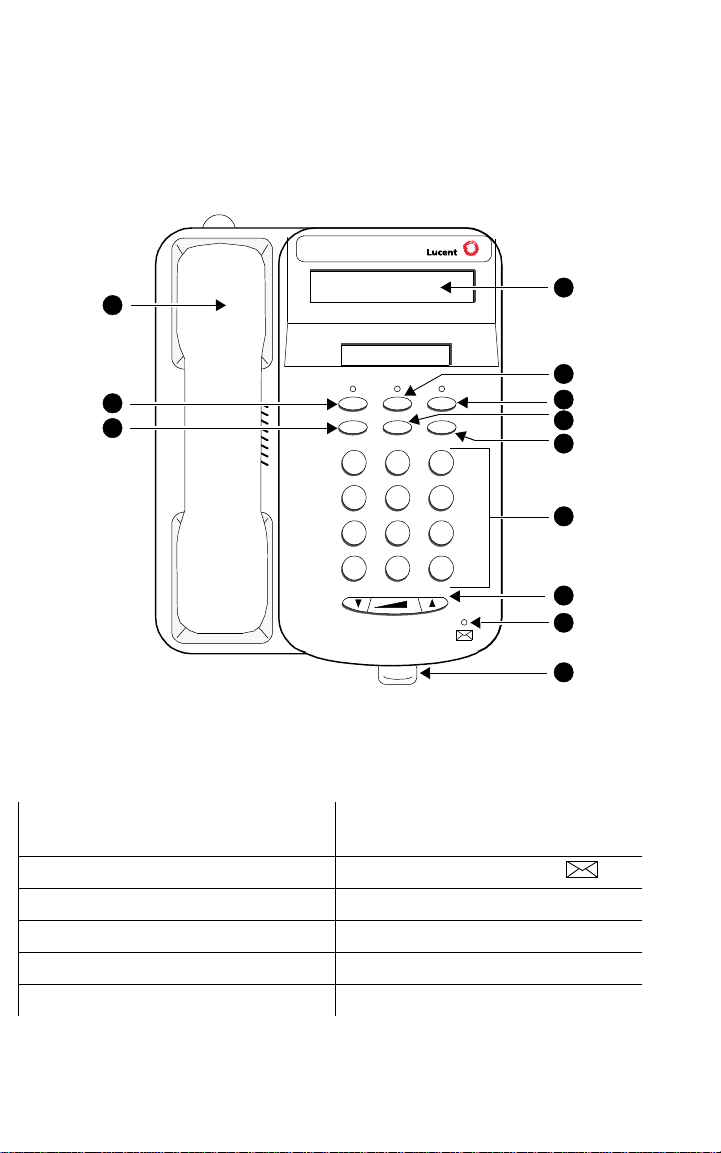
The 6402 and 6402D Telephones
There are two 6402 telephones: the basic 6402 telephone and the 6402D,
which has a 2-line, 16-character display. Fam iliarize yourself with the features
on the 6402 and 6402D telephone, shown in Figure 1 below.
Note: The 6402 and 6402D telephones are exactly the same except for the
display which appears only on the 6402D.
12
Tel #
11
10
Spkr Feature Hold
Redial Trns fr Conf
Test Rin g
DEF
ABC
1
2
GHI
PQRS
*
4
7
MNOJKL
56
TUV
WXYZ
8
O
3
9
#
FIGURE 1 The 6402D Telephone
The following features correspond to the numbers in Figure 1.
1) Display — available only on the
6402D 7) Volume control butt on
2) Feature button 8) Message light — labeled
3) Hold button 9) Tray handle
4) Transfer/Test button) 10) Redial button
5) Conf/Ring button 11) Speaker button
6) Dial pad 12) Handset
1
2
3
4
5
6
7
8
9
1
Page 6
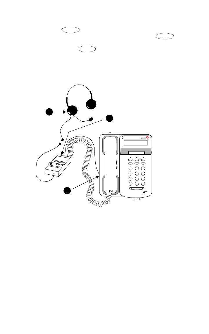
Headsets
Feature
Headsets for 6400 Series telephones allow one-touch hands-free operation.
To answer a call, press and then the dial pad key on which the
Headset feature is adm in is tere d. (Fo r more information on using and
the dial pad keys to access features, see “Voice Features” later in this
manual.) To disconnect, press again and then the dial pad key on
Feature
which the Headset feature is administered.
Headsets consist of a headpiece (1 in Figure 2 below) and modular base
unit (2). The base unit plugs into the Handset jack (3).
1
2
4*56
7
89
O
3
Volum e
Feature
321
#
FIGURE 2 The Headset Attached to a 6402D Telephone
Headpieces
The following headpieces can be used with these telephones:
®
— Mirage
— StarSet
— Supra® Monaural — Adjustable headband and soft ear cushion.
— Supra Monaural Noise-Canceling (NC) — Same as above with
noise-canceling microphone that reduces background noise transmission
by up to 75 percent.
— Supra Binaural — Sound in both ears.
— Supra Binaural Noise-Canceling (NC) — Same as above with
noise-canceling microphone on flexible boom; features windscreen and
reduces background noise transmission by up to 75 percent.
— Receiver fits over either ear. Not for noisy environments.
®
— Eartip fits in ear canal.
2
Page 7

Note: The privacy of the Whisper Page announcement cannot be
guaranteed when telephones have modular base units other than the
M10L-8400 plugged into the Handset jack. The M10L-8400
(Comcode: 407639715; PEC: 3 122-022 ) is th e only modula r base unit
that should be used for the 6400 Series terminals. For more
information, see the instructions for the Whisper Page feature in the
Voice Features section.
Call-Handling Features
Conference
The Conference feature allows you to conference up to six parties (including
yourself) on a call.
To add another party to a call (for a total of six parties)
1. Press .
2. Dial the number of the new party and wait for an answer.
3. When you want to add the new person, press again.
4. Repeat Steps 1 through 3 for additional conference connections.
To add a call you have put on hold to another call you are
connected to
1. Press .
2. Press and then release the switchhook.
3. Press again.
Conf
Conf
Conf
Conf
Hold
The Hold feature puts a call on hold until you can return to it.
T o keep a call on hol d while you answ er another ca ll or perform anothe r
task
Conf
Hold
Hold
without
Trnsfr
first returning to the held call.
3
1. Press .
T o answ er a new call while active on another
1. Press .
2. To be connected to the incoming call, press and then release the
switchhook.
To return to the held call
1. Press and then release the switchhook again.
Note: If your telephone is connected to DEFINITY Release 7.1 or a later
release and if there is only one call on hold at your telephone, you can
transfer the call or initiate a conference call by pressing or
Page 8
Redial
The Redial (or Last Number Dialed) feature automatically redials the last
extension or outside number you dialed.
To redial the last number that you dialed
1. Press .
Redial
The redialed number can be an outside numbe r (up to 24 digits), an extension,
or a trunk or feature access code.
Speaker (Listen-Only)
Note: The Speaker feature allows you to pla ce call s or acces s other f eatures
without lifting the handset. However, in order to speak to the other
party, you must use the handset.
To place a call without lifting the handset or for any listening-only
feature (such as monitoring a call on which you have been put on hold)
1. Press .
2. Place a call or access the selected feature.
3. Adjust the speaker volume if necessary:
To raise the volume, press the right half of the Volume control button
labeled ; to lower the volume, press the left half of the Volume
control button labele d . If you have a displa y, it shows the volume
level:
Spkr
->>>>>> +
To change from the speaker to the handset
1. Lift the handset and talk.
To change from the handset to the speaker
1. While the handset is off-hook, press .
Spkr
You can now hang up the handset (within 10 seconds) and the call will
remain active on the speaker. However, in order to talk to the other
party, you must use the handset.
To end a call (while the handset is on-hook and only the speaker is
active)
1. With the handset on-hook, press .
Spkr
4
Page 9

Test
The Test feature allows you to test the lights on your telephone and the
display, if the telephone has one.
To test the lights and display on the telephone
1. While on-hook, press and hold down .
Trnsfr
The lights go on steadily, and, if your telephone has a display, all the
display segments fill in.
2. To end test, release .
Trnsfr
Lights return to normal operation.
Note: If the display or the lights do
system manager.
not
respond during the test, notify your
Transfer
The Transfer feature allows you to transfer a call from your telephone to
another extension or outside number.
To send the present call to another extension
1. Press .
2. Dial the number to which the call is to be transferred.
3. Remain on the line and announ ce th e c al l. (If the line is busy or i f there
is no answer, you can return to the held call by pressing and then
releasing the switchhook.)
4. Press again to complete the transfer.
5. Hang up.
Note: If your telephone is connected to DEFINITY Release 6.3.2 or a later
release, your administrator may have chosen Transfer-on-Hang-up. In
this case, you can transfer a call by pressing , dialing the
number to which the call is to be transferred, and then hanging up.
To cancel an attempted transfer, press and release the switchhook or
press and then the dial pad key on which the Drop feature is
administered.
Trnsfr
Trnsfr
Trnsfr
Feature
Getting Messages
Message
Your Message light goes on when a caller has left a message for you.
For directions on retrieving your messages, see your system manager.
5
Page 10

Selecting a Personalized Ring
Select Ring
The Select Ring feature allows you to choose your own personalized ringing
pattern for your telephone from among eight different patterns.
To select a personalized ringing pattern
1. While on-hook, press .
Current ringing pattern plays and repeats every three seconds.
2. Continue to press (and then relea se) to cycle through all e igh t
ringing patterns.
3. If you want to save the ringing pattern currently being played, do not
press anymore. You will hear the selected ringing pattern two
more times, and then it will be automatically saved.
Conf
You will hear a confirmation tone (two rising tones) and your new
ringing pattern is set.
Note: If you go off-hook, receive a call, or lose power while selecting a
ringing pattern, the process is interrupted and you must start again.
Conf
Conf
Selected Voice Features
How to Access a Voice Feature on the 6402 and 6402D
When you want to use one of the voice features on the 6402 or 6402D
telephone, you can access the feature in one of two ways:
• You can access up to 12 features by pressing and then the dial
pad key (1 through 9, or 0, * or #) that corresponds with that feature.
These features are administered on your telephone by your system
manager. (The red light next to goes on steadily when the button
is pressed to let you know that your dial pad is now in the Feature
selection mode.)
For example, if t he Send All Cal ls f eature is a ssigned to F1, you ca n press
Feature
, then dial in order to use this feature. If you have
programmed your home number on an Abbreviated Dialing button
assigned to F*, you c an press and then press on your dial pad
whenever you want to use this AD button.
Note: As your system manager assigns features to the Fe ature Direct ory slots
(1 through 9, 0, *, and #), be sure to write the feature on the Feature
Directory card (shown in Figure 3) in the tray located under the base of
the telephone. This directory list provides a convenient quick reference
for the 12 features programmed on the dial pad.
1
Feature
Feature
Feature
*
6
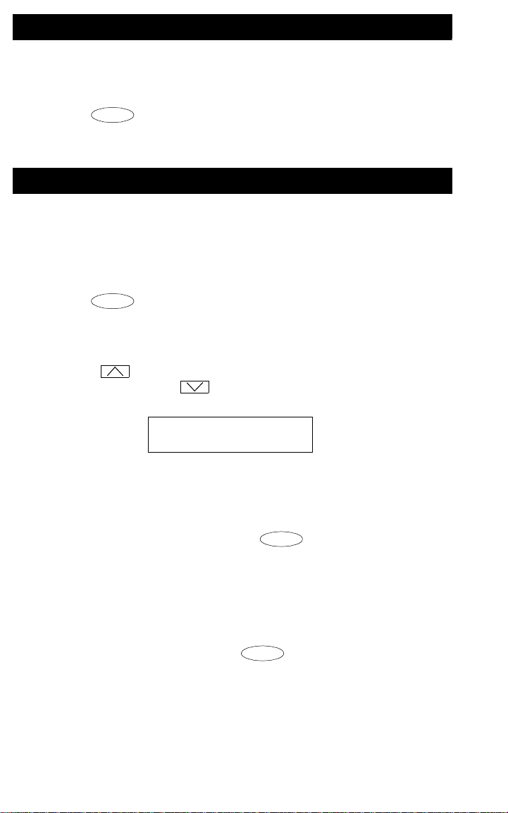
Page 11

FEATURES ADMINISTERED ON
6402 DIAL PAD
Dial
Pad
Key
Feature Administered
on that Key
1
2
3
4
FIGURE 3 The 6402 and 6402D Telephone Feature Directory
• Features other than those assigned to your Feature Directory can be
accessed by simpl y dia ling a 1- , 2-, o r 3-digi t featu re acces s code , wit hout
Feature
using . Your system manager can supply those access codes for
you. You may write feature codes on the Feature Access Code quick
reference list in the tray located under the base of the telephone.
Abbreviated Dialing (AD)
The Abbreviated Dialing (AD) feature allows you to store selected telephone
numbers for quick and easy dialing. Each number can be a complete or
partial telephone number, an extension number, or a trunk or feature access
code. Abbreviated Dialing offers four possible types of lists — Personal,
Group, System, and Enhanced, and you can have a total of three lists. (Of
these three lists, you c an have onl y one Syste m List and o ne Enhanced List.)
You program numbers on a Personal List; numbers on Group Lists are
programmable by the controller of the list; System Lists and Enhanced Lists
are programmable only by the system manager.
To program/reprogram an AD entry on your Feature Directory
Note: The system manager must program a feature button as an AD
button before you can program a number onto it.
Note: If your telephone is connected to DEFINITY Release 6.2 or
earlier release, there is a 10-second time limit between your
going off-hook and entering the first digit of an AD button, and
then a 10-second time limit between each digit. If you hear
intercept tone while you are programming the button, you have
exceeded the time limit and you must begin again.
1. While off-hook, press , then the dial pad key assigned to the
AD Program feature
OR, while off-hook, dial the Program access code.
Feature
[dial tone]
7
Page 12

2. Press , then the dial pad key you wish to program.
Feature
For example, to store a number in AD entry F3, press , then
3
the dial pad key.
[dial tone ]
Feature
3. Dial the outside number , extensio n, or feature a ccess code you wan t to
store (up to 24 digits).
4. Press . [confirmation tone, then dial tone]
#
5. Repeat Steps 2 through 4 to program additional buttons.
6. Hang up to end programming.
To place an AD call from your Feature Directory
1. While off-hook, press , then the dial pad key which
Feature
corresponds with the AD number you wish to call. [ringback tone]
For example, to call the num be r stored as AD entry F3, press ,
then press the dial pad key.
3
To program or reprogram a Personal List item
1. On a separate sheet of paper, write down the outside numbers,
extensions, and/or feature access codes you want to program as items
on your Personal List(s).
2. While off-hook, dial the Abbreviated Dialing Program access code.
[dial tone]
3. Dial the Personal List number (1, 2, or 3).. [dial tone]
4. Dial the list item (1, 2, 3...). (See your system manager for the number
of Personal List items you can program.) [dial tone]
5. Dial the number you want to store (up to 24 digits).
6. Press . [confirmation tone, then dial tone]
#
Number is stored.
7. Repeat Steps 4 through 6 if you want to program additional items on
the same list. Hang up and begi n again at Step 2 if you want to
program items on another personal list.
8. Hang up.
9. Record your personal list items on the Abbreviated Dialing list on the
appropriate card in the tray under the base of the telephone.
Feature
To place a call using an AD list button or code
1. Press , then the app ropriate dial pad key on which a list access
Feature
code is administered.
OR, dial the appropriate AD List code:
List 1 __________
List 2 __________
List 3 __________
8
Page 13

2. Dial the desired list item (1, 2, 3...). [ringback tone]
Call is automatically dialed.
Note: Keep your own Personal L ists on the card s in the tra y unde r the
base of the telephone. System, Group, and Enhanced lists are
available from your system manager.
Call Forwarding All Calls
The Call Forwarding feature temporarily forwards all your calls to another
extension or to an outside number, depending on your system.
To temporarily redirect all calls to an extension or outside number
1. Press (while off-hook), then the dial p ad k ey on w hic h th e Cal l
2 . D ial th e e x t e n s ion or te l e p h o n e numbe r w h e r e c alls w i l l b e s e nt.
3. Hang up.
To cancel Call Forwarding
1. Press (while off-hook), then the dial p ad k ey on w hic h th e Cal l
Feature
Forwarding feature is administered
OR, dial the Call Forward access code (while off-hook). [dial tone]
[confirmation tone]
Feature
Forwarding feature is administered [dial tone]
OR, dial the Call Forward cancel code (while off-hook).
[confirmation tone]
Your calls will now ring at your own telephone.
Call Park
The Call Park feature allows you to put a call on hold at your telephone for
retrieval at any extension.
To park a call at your extension (for retrieval at any extension)
1. Press . [dial tone]
2. Dial the Call Park access code. [confirmation tone]
3. Press again.
Call is parked at your extension.
4. Hang up.
To return to a call parked at your extension
1. Dial the Call Park Answer Back code. [dial tone]
2. Dial your own extension number. [confirmation tone]
You are reconnected to the call.
To retrieve a parked call at another extension
1. Dial the Call Park Answer Back access code. [dial tone]
2. Dial the extension where the call is parked. [confirmation tone].
Trnsfr
Trnsfr
9
Page 14

Call Pickup
The Call Pickup feature lets you answer a call at your telephone for another
extension in your pickup group.
Note: You can use this feature only if you and the called party have been
assigned to the same pickup group by your system manager.
To answer a call placed to a member of your pickup group when your
telephone is idle
1. Press (while of f - hoo k), t hen the dial pad k ey on w hi ch the Call
Pickup feature is administered
OR, dial the Call Pickup access code (while off-hook).
You are connected to the ringing call.
To pick up a call when you are already active on another call
Note: Depending on how your system is administered, you may not be able
1. Press .
Present call is put on hold and the red light next to blinks.
2. Press , then the dial pad key on which the Call Pickup feature
is administered
OR, dial the Call Pickup access code.
Called telephone stops ringing and you are connected to the ringing
call.
Note: To return to the held call after completing the call you have
Feature
to use this procedure on your telephone. See your system manager
for more details.
Hold
Hold
Feature
picked up, press and then release the switchhook.
Leave Word Calling
The Leave Word Calling (LWC) feature leaves a message for another
extension to call you back. The called party will be able to dial message
service (for example, an attendant, AUDIX
covering user, etc.) to retrieve a short, standard message which gives your
name and extension, the date and time you called, and the number of times
you called.
To leave a message
after
dialing an extension (when your call is not
answered, you hear a coverage or busy tone, or you have been put on
hold)
1. Press , then the dial pad key on which the Leav e Word Calling
Feature
feature is administered. [confirmation tone]
Message light goes on at the called telephone (if so equipped).
10
®
or other voice mail system, a
Page 15

To leave a message without ringing an extension
1. Press , then the dial pad key on which the Leav e Word Calling
Feature
feature is administered
OR, dial the Leave Word Calling access code.
2. Dial the extension.
Message light goes on at the called telephone (if so equipped).
To cancel a Leave Word Calling message
Note: You cannot cancel a message left for an AUDIX subscriber.
1. Press (while off-hook), then the dial pad key on which the
Feature
Leave Word Calling Cancel feature is administered
OR, dial the Leave Word Calling cancel code (while off-hook).
2. Dial the extension.
Send All Calls
The Send All Calls feature temporarily sends all your calls to another
extension in the same system.
Note: Before you can us e this fea ture, your system manager mus t provide a
coverage path for your extension.
To send all calls (except priority calls) immediately to coverage
1. While on-hook, press , then the dial pad key on which the
Send All Calls feature is administered
OR, dial the Send All Calls access code (while off-hook).
[confirmation tone]
To cancel Send All Calls
1. While on-hook, press again, then the dial pad key on which
the Send All Calls feature is administered
OR, dial the Send All Calls cancel code (while off-hook).
[confirmation tone]
Feature
Feature
Whisper Page
The Whisper Page feature allows you, if you have the appropriate
permissions, to make an announcement to a person at another extension
currently on another call. Only the person at the other extension hears the
announcement; the other person on the call cannot hear the message.
Note: The M10L-8400 is the only modular base unit that should be plugged
into the Handset jack on th e 64 00 Se ries tel eph on es. If other modular
base units are used, the Whisper Page announcement may be
overheard by the other person on the call.
To make an important announcement (such as an incoming call) to
someone at another extension busy on another call
1. Lift the handset and press . Then press the dial pad key on
which the Whisper Page feature is administered
Feature
11
Page 16

OR, dial the Whisper Page access code.
2. When you hear dial tone, dial the extension of the other person.
The people on the other call hear a beep.
The person whom you have called may activate the Whisper Page
Answer feature by using either the feature access code or by pressing
Feature
and then the dial pad key on which the Whisper Answer
feature is administered. This will form a two-party speaking path with
your telephone. The other call is put on hold.
3. Speak with the person you have called.
4. When you are finished, the person whom you called can retrieve the
first call from h old , if he /she is using a 6402 or 6402D, by pressing an d
then releasing the switchhook.
Note: A person can bloc k int erruptio ns from the W hispe r Page fe ature
by deactivating the feature with the Whisper Page Off feature.
(This feature can be accessed while off-hook by using the
feature access code or by pressing and then the
Whisper Page Off entry number or * or #.)
Feature
Using the Display on the 6402D
Note: The 6402D can be used only with a DEFINITY ECS Release 6.3 or
later.
Note: Only the 6402D telephone has a 2-line by 16-character display. The
basic 6402 t elephone does not have a display.
The primary uses for the display on the 6402D telephone are:
• Viewing the time and date, which is the usual display. (See Figure 4.)
• Using the Call Timer or the T imer feature (if adminis tered on y our dial pad)
which shows elapsed time on a call. (See Figure 4.)
10:19am 3/27/98 Time and date
0:09:07
FIGURE 4 Date, Time, and Timer on the 6402D Display
Timer screen
screen
• Viewing call-handling information.
As you dial a telephone number, the individual digits are immediately
shown on the display as you dial them. When you dial an extension, that
number is shown and then re place d by the call ed pa rty’ s na me. (If th ere is
not space for the full name, as many letters of the name as possible will
be shown on the display.)
When a call is received from another extension, the caller’s name is
shown; when a call is received from outside, “OUTSIDE CALL” or a trunk
identifier is shown.
• When you set the handset, speaker, or ringer volume, the display shows
12
Page 17

the volume level.
Note: When a 6400 Series display telepho ne is ini tially plugge d in or after a
power outage, it can take up to 15 minutes before the time and date
appear on the screen.
Installation
The 6402 and 6402D can be either desk-mounted or wall-mounted. Use the
following directions for installing either telephone. Figure 5 shows the back of
the 6402 and 6402D telephones.
1
2
LINE
3
456
FIGURE 5 The Bottom of the 6402 and 6402D Telephones
Desktop Installation
Note: You may use the 6400 Series telephones
In this case it is su ggeste d that yo u place s mall round feet (incl uded i n
a plastic bag in the box in which the telephone was packed) on each
corner of the bottom of the telephone housing.
1. Turn the telephone face down on a flat surface.
2. Snap one end of the line cord (D2R or D8W) into the “LINE” jac k on the
back of the telephone (shown as 3 in Figure 5).
3. Thread the line cord through the routing channel leading to the top of
the desktop stand (2 in Figure 5). Make sure that the cord is placed
securely under the square tabs in the routing channel.
without
the desktop stand.
13
Page 18

4. Snap one end of the coiled handset cord into the Handset jack (5 in
Figure 5). This ja ck i s l abe le d . Thread the cord i nto the c han nel
leading to the side edge of the voice terminal (4 in Figure 5).
5. Turn the telephone right side up, with the front facing you.
6. Snap the free end of the handset cord into the handset and place the
handset in the cradle.
7. Snap the free end of the line cord into the modular wall jack.
8. Lift the handset and listen for dial tone. If there is no dial ton e, check all
wire connections to make sure they are secure.
Wall Installation
Note: For wall-mounting, you will need a 1-foot line cord. This cord is
supplied with the telephone, but can be ordered by using this
comcode: 103786760.)
If you are wall-mounting the telephone, you should remove the
tray from the base of the telephone. For this purpose, use the
instructions listed under “Removing the Telephone Tray” later in this
guide.
1. Make sure the 8-conductor wall mount plate is in place.
2. Do the following to reverse the handset hook. (The handset retainer is
located under the handset as shown in a in Figure 6.)
— In orde r to release the hand set retainer hook, pres s down on the hook
and slide it toward the top of the telephone. (See b in Figure 6.)
— Rotate the hook 180 degrees (as in c in Figure 6) and then slide it
back into its slot so the bottom part now sticks out from the top. (See
d in Figure 6.) Snap the hook firmly into place.
not
a.
c.
b.
d.
¾
FIGURE 6 Removing, Rotating, and Replacing the Handset Retainer
14
Page 19

3. Place the telephone face down on a flat surface.
4. Remove the desktop stand which is attached to the base of the
telephone by tabs (shown as 1 in Figure 7) on the top and back of the
stand.
— Press inward on the top of the stand until you can lift the top of the
stand out of the tab slot (shown as 2 in Figure 7) on the back of the
telephone.
— Lift the bottom of the stand out of the lower tab slot(s).
1
2
FIGURE 7 Removing the Desktop Stand
5. Turn the desktop stand so that the larger end is facing down.
6. Reinstall the stand using the tabs and tab slots shown in Figure 7.
7. Snap the line cord into the “LINE” jack in the bottom of the telephone
and coil the excess cord in the back of the deskstand.
8. Snap one end of the coiled handset cord into the Handset jack
(labeled ).
9. Snap the free end of the line cord into the wall jack.
10. Place the base of the telephone on the wall-jack mounting studs,
and pull downward until it is secure. (See Figure 8.)
15
Page 20

FIGURE 8 Placing the T e lephone on the Wall Jack Mounting Studs
11. Snap the free end of the handset cord into the handset and place the
handset in the cradle.
Note: The handset hook you repositioned will hold the handset in place.
12. Lift the handset and listen for dial tone. If there is no di al tone, check all
wire connections to make sure they are secure.
16
Page 21

Removing the Telephone Tray
You may wish to remove the tray from the base of the telephone, especially if
you are wall-mounting the telephone. See Figure 9 for further help.
1. Pull the tray from the base of the telephone as far as it will go.
2. Using your thumb, press down on the center of the tray.
3. Continue to pull the tray until it is completely separated from the base.
1
2
3
FIGURE 9 Removing the Tray from the Base of the Telephone
17
Page 22

Installing the Telephone Number Card
Hold
Use the telephone number card (labeled Tel No.) to write your telephone
number or extension.
To label and install the telephone number card on your 6402 or 6402D
telephone
1. Print your phone number or extension on the Tel. no. card.
2. Crease the perforated edges of the station number card and separate
the telephone number card along the perforations.
3. Remove the telephone number card cover (located above ,
Feature
, and by applying pressure toward the other end of the
cover. See Figu re 10.
4. Place the completed telephone number card into the number card
holder, the area from which you removed the telephone number card
cover.
5. Replace the telephone number card cov er by inserting one end into its
slot. Then, slightly flex the plastic and slip the other end into its slot.
Tel #:
Spkr
T
e
l
#
S
p
k
r
F
e
a
t
u
r
e
H
o
l
d
FIGURE 10Removing and Reinstalling the Telephone Number
Card Cover
Note: You can order additional designation cards in quantities of 25 cards
and 100 cards per package. Use the following comcodes when you
place your order.
25 sheets of designation and telephone number cards:
Comcode: CC847984614
100 sheets of designation and telephone number cards:
Comcode: CC847984622
18
Page 23

Tones and Their Meaning
Note: The tables below describe the defaults for each ringing and feedback
tone. Check with your system manager to verify that the descriptions
in the Meaning column are accurate for your system.
Ringing T o nes are produced by an incoming call.
Ringing Tones
Rings Meaning
1 ring A call from another extension.
2 rings A call from outside or from the
attendant.
3 rings A priority call from another extension, or
from an Automatic Callback call you
placed.
◆
Feedback tones are those which you hear through the handset (receiver) or
the speaker.
ring-ping
(half-ring)
A call redirected from you r telep hone to
another because Send All Calls or Call
Forwarding All Calls is active.
Feedback Tones
Tones Meaning
busy A low-pitched tone repeated 60 times a
minute; indicates the number dialed is in
use.
call waiting
ringback
confirmation Three short bursts of tone; indicates a
A ringback tone with low er-p itche d s ign al
at the end; indicates the extension call is
busy , and the cal led party has bee n given
a call waiting tone. If you hear this tone,
you may wish to activate Automatic
Callback.
feature activation or cancellation has
been accepted.
19
continued on next page
Page 24

Feedback Tones
Tones Meaning
(continued)
coverage One short burst of tone; i ndica tes you r call
will be sent to another extension to be
answered by a covering user.
dial A continuous tone; indicates dialing can
begin.
intercept/
time-out
recall dial Three short bursts of tone followed by a
reorder A fast busy tone repeated 120 times a
ringback A low-pitched tone repeated 15 times a
An alternating high and low tone; indic ates
a dialing error, a denial of the service
requested, or a failure to dial within a
preset interval (usually 10 seconds) after
lifting the handset or dialing the previous
digit.
steady dial tone; indicates the feature
request has been accepted and dialing
can begin.
minute; indicates all trunks are busy.
minute; indicates the number dialed is
being called.
Line and Feature Button Lights
Line and Feature Button Lights
Light Meaning
Steady red light next to
Feature
and next to
Spkr
Blinking red light next to You have put a call on hold. In order to
Hold
The red light next to
know that the dial pad is now in
Feature selection mode. The red light
next to means that the
one-way speaker is on.
return to the call, press and then
release the switchhook.
20
Spkr
Feature
lets you
 Loading...