

Mitsubishi Heavy Industries SRR25ZM-S, SRR35ZM-S Technical Manual

TECHNICAL MANUAL
-ANUAL.Ogs324
INVERTER CEILING CONCEALED TYPE
RESIDENTIAL AIR
-
CONDITIONERS
3PLITSYSTEMAIRTOAIRHEATPUMPTYPE
322:-3
322:-3
TECHNICAL MANUAL
updated April 10, 2017

-
1
-
'15 • SR-T-185
gs32+4
CONTENTS
1. SPECIFICATIONS ........................................................................................ 3
(2) Outdoor units ....................................................................................... 6
..................................................... 17
2EMOTECONTROL
..................................................................................... 7
......................................................................... 5
(1) Indoor units
2. EXTERIOR DIMENSIONS
3. ELECTRICAL WIRING .............................................................................. 10
(1) Indoor units .......................................................................................... 10
4. NOISE LEVEL ............................................................................................ 12
5. CHARACTERISTICS OF FAN ................................................................... 16
(2) Outdoor units ....................................................................................... 11
7. RANGE OF USAGE & LIMITATIONS
................................................................................... 19
8. CAPACITY TABLES
6. PIPING SYSTEM ...................................................................................... 16
.................................................................................. 20
9. APPLICATION DATA
10. OUTLINE OF OPERATION CONTROL BY MICROCOMPUTER ............... 32
3ILENTMODE
............................... 33
/PERATIONCONTROLFUNCTIONBYWIRELESSREMOTECONTROL
4IMEROPERATION
3ELECTIONOFTHEANNUALCOOLINGFUNCTION .............................................. 34
)NSTALLINGTWOAIRCONDITIONERSINTHESAMEROOM
......................................................................... 33!UTORESTARTFUNCTION
5NIT/./&&BUTTON
........................................................................... 33
....................... 32
)NSTALLATIONOFINDOORUNIT ...................................................................... 20
)NSTALLATIONOFOUTDOORUNIT .................................................................. 24
%CONOMYOPERATION
.............................................................................. 34
(IGHPOWEROPERATION ........................................................................... 34
.IGHTSETBACK
/UTLINEOFHEATINGOPERATION
/UTLINEOFDRYDEHUMIDIFYINGOPRATION .............................................. 37
/UTLINEOFCOOLINGOPERATION ............................................................... 37
/UTLINEOFAUTOMATICOPERATION ........................................................... 38
0ROTECTIVECONTROLFUNCTION
................................................................... 38
)TEMSTOCHECKBEFORETROUBLESHOOTING ................................................. 44
............................................................................... 44
#AUTIONS
............................................................................................. 44
11. MAINTENANCE DATA
-
2
-
'15 • SR-T-185
(10) How to make sure of wireless remote control ...................................... 61
(12) Outdoor unit inspection points .............................................................. 62
(11) Inspection procedure for blown fuse on the indoor and outdoor PCB .... 61
(8)
Phenomenon observed after shortcircuit, wire breakage on sensor
......... 59
(9) Checking the indoor electrical equipment
........................................... 59
■How to read the model name
Example: SRR 25 Z
Series code
Inverter type
Product capacity (Cooling capacity : 2.5kW)
Model name SRR : Ceiling concealed type
SRC : Outdoor unit
M-S
........................................................................................... 64
12. OPTION PARTS
...................................................................... 87
13. TECHNICAL INFORMATION
............................................................................ 64
..................................................................... 78
(1) Wired remote control
(2) Interf
ace kit (SC-BIKN-E)
(3) Superlink E board (SC-ADNA-E) .......................................................... 82
(5) Remote sensor kit (SC-THB-E3) .......................................................... 85
(4) Bottom air inlet kit
(6) Service mode (Trouble mode access function) ................................... 47
(7) Inspection procedures corresponding to detail of trouble .................... 55
..................... 45
(4) Troubleshooting procedure (If the air-conditioner runs)
(5) Self-diagnosis table ............................................................................. 46
................................................................................ 84
(3) Troubleshooting procedure
(If the air-conditioner does not run at all)
........ 44

-
3
-
'15 • SR-T-185
1. SPECIFICATIONS
Model SRR25ZM-S
Model
Item
SRR25ZM-S
Indoor unit SRR25ZM-S Outdoor unit SRC25ZMX-S
Power source 1 Phase, 220 - 240V, 50Hz
Operation data
Nominal cooling capacity (range) kW 2.5 ( 1.0 (Min.) - 3.3 (Max.))
Nominal heating capacity (range) kW 3.4 ( 1.4 (Min.) - 4.8 (Max.))
Power consumption
Cooling
kW
0.570 ( 0.21 - 0.86 )
Heating 0.750 ( 0.26 - 1.32 )
Max power consumption 1.65
Running current
Cooling
A
3.0 / 2.9 / 2.8 (220/ 230/ 240 V)
Heating 3.9 / 3.7 / 3.6 (220/ 230/ 240 V)
Inrush current, max current 3.9 / 3.7 / 3.6 (220/ 230/ 240 V), MAX 8
Power factor
Cooling
%
85
Heating 88
EER 4.39
COP 4.53
Sound power level
Cooling
dB(A)
56 60
Heating 59 60
Sound pressure level
①
Cooling Hi: 37 Me: 33 Lo: 30 ULo: 24 47
Heating Hi: 40 Me: 37 Lo: 34 ULo: 28 47
Sound pressure level
②
Cooling Hi: 31 Me: 28 Lo: 26 ULo: 21 47
Heating Hi: 33 Me: 30 Lo: 28 ULo: 23 47
Sound pressure level
③
Cooling Hi: 39 Me: 35 Lo: 32 ULo: 25 47
Heating Hi: 44 Me: 41 Lo: 38 ULo: 31 47
Silent mode sound pressure level — Cooling:41 / Heating:42
Exterior dimensions (Height x Width x Depth) mm 200 x 750 x 500 595 x 780(+62) x 290
Exterior appearance ( Munsell color ) —
Stucco white
( 4.2Y 7.5/1.1 ) near equivalent
Net weight kg 20.5 35
Compressor type & Q'ty — RM-B5077MDE1( Rotary type ) x 1
Compressor motor (Starting method) kW — 0.75 ( Inverter driven )
Refrigerant oil (Amount, type) — 0.35 ( DIAMOND FREEZE MA68 )
Refrigerant (Type, amount, pre-charge length) kg R410A 1.2 in outdoor unit (incl. the amount for the piping of 15m )
Heat exchanger Louver fins & inner grooved tubing M fins & inner grooved tubing
Refrigerant control Capillary tubes + Electronic expansion valve
Fan type & Q'ty Centrifugal fan x 2 Propeller fan x 1
Fan motor (Starting method) W 51 x1 (Direct drive) 24 x1 (Direct drive)
Air flow
Cooling
m3/min
Hi: 9.5 Me: 8.0 Lo: 6.5 ULo: 4.5 29.5
Heating Hi: 10.0 Me: 9.0 Lo: 8.0 ULo: 6.0 27.0
Available external static pressure Pa 35 (Initial static pressure with air filter:5Pa) 0
Outside air intake Not possible —
Air filter, Quality / Quantity Polypropylene net x 1 —
Shock & vibration absorber Cushion rubber (for fan motor) Rubber sleeve (for fan motor & compressor)
Electric heater — —
Operation
control
Remote control Wireless remote control
Room temperature control Microcomputer thermostat
Operation display RUN: Green, TIMER: Yellow, HI POWER: Green, ECONO: Green
Safety equipments
Compressor overheat protection, Overcurrent protection, Drain error protection,
Frost protection, Serial signal error protection, Indoor fan motor error protection,
Heating overload protection( High pressure control ), Cooling overload protection
Installation
data
Refrigerant piping size (O.D) mm Liquid line: φ6.35 ( 1/4" ) Gas line: φ9.52 ( 3/8" )
Connecting method Flare connection Flare connection
Attached length of piping m — —
Insulation for piping Necessary (Both sides), independent
Refrigerant line (one way) length m Max. 15
Vertical height diff. between O.U. and I.U.
m Max. 10 (Outdoor unit is higher) / Max. 10 (Outdoor unit is lower)
Drain hose
Hose connectable ( VP 25 ) Holes φ20 x 2 pcs
Drain pump, max lift height mm Built-in, MAX600 —
Recommended breaker size A 16
L.R.A. (Locked rotor ampere) A 3.1 / 2.9 / 2.8 (220/ 230/ 240 V)
Interconnecting wires Size x Core number 1.5mm2 x 4 cores (Including earth cable) / Terminal block (Screw fixing type)
IP number IPX0 IPX4
Standard accessories Mounting kit, Joint for drain piping
Option parts Wired remote control, Interface kit ( SC-BIKN-E ), Bottom air inlet kit
Note (1) The data are measured at the following conditions.
Item
Operation
Indoor air temperature
Outdoor air temperature
Standards Note
DB WB DB WB
Cooling 27˚C 19˚C 35˚C 24˚C
ISO5151-T1
Non-duct
(with air fillter)
Heating 20˚C — 7˚C 6˚C
(2) This air-conditioner is manufactured and tested in conformity with the ISO.
(3) Sound level indicates the value in an anechoic chamber. During operation these
values are somewhat higher due to ambient conditions.
(4) Select the breaker size according to the own national standard.
The pipe length is 5m.
RWA000Z2 6 3
① ②
③
External static
pressure
for ②, ③
: 10Pa
(5) Mike positions of measureing sound pressure
level of indoor unit is shown below.
-
4
-
'15 • SR-T-185
Model SRR35ZM-S
Model
Item
SRR35ZM-S
Indoor unit SRR35ZM-S Outdoor unit SRC35ZMX-S
Power source 1 Phase, 220 - 240V, 50Hz
Operation data
Nominal cooling capacity (range) kW 3.5 ( 1.0 (Min.) - 3.9 (Max.))
Nominal heating capacity (range) kW 4.2 ( 1.5 (Min.) - 5.2 (Max.))
Power consumption
Cooling
kW
0.980 ( 0.21 - 1.20 )
Heating 1.030 ( 0.260 - 1.47 )
Max power consumption 1.65
Running current
Cooling
A
4.7 / 4.5 / 4.3 (220/ 230/ 240 V)
Heating 5.0 / 4.8 / 4.6 (220/ 230/ 240 V)
Inrush current, max current 5.0 / 4.8 / 4.6 (220/ 230/ 240 V), MAX 8
Power factor
Cooling
%
94
Heating 93
EER 3.57
COP 4.08
Sound power level
Cooling
dB(A)
57 62
Heating 60 62
Sound pressure level
①
Cooling Hi: 38 Me: 34 Lo: 31 ULo: 25 50
Heating Hi: 42 Me: 38 Lo: 35 ULo: 29 50
Sound pressure level
②
Cooling Hi: 33 Me: 30 Lo: 27 ULo: 22 50
Heating Hi: 34 Me: 32 Lo: 29 ULo: 24 50
Sound pressure level
③
Cooling Hi: 40 Me: 37 Lo: 33 ULo: 27 50
Heating Hi: 45 Me: 42 Lo: 39 ULo: 33 50
Silent mode sound pressure level — Cooling:45 / Heating:43
Exterior dimensions (Height x Width x Depth) mm 200 x 750 x 500 595 x 780(+62) x 290
Exterior appearance ( Munsell color ) —
Stucco white
( 4.2Y 7.5/1.1 ) near equivalent
Net weight kg 20.5 35
Compressor type & Q'ty — RM-B5077MDE1( Rotary type ) x 1
Compressor motor (Starting method) kW — 0.90 ( Inverter driven )
Refrigerant oil (Amount, type) — 0.35 ( DIAMOND FREEZE MA68 )
Refrigerant (Type, amount, pre-charge length) kg R410A 1.2 in outdoor unit (incl. the amount for the piping of 15m )
Heat exchanger Louver fins & inner grooved tubing M fins & inner grooved tubing
Refrigerant control Capillary tubes + Electronic expansion valve
Fan type & Q'ty Centrifugal fan x 2 Propeller fan x 1
Fan motor (Starting method) W 51 x1 (Direct drive) 24 x1 (Direct drive)
Air flow
Cooling
m3/min
Hi: 10.0 Me: 8.5 Lo: 7.0 ULo: 5.0 32.5
Heating Hi: 10.5 Me: 9.5 Lo: 8.5 ULo: 6.5 29.5
Available external static pressure Pa 35 (Initial static pressure with air filter:5Pa) 0
Outside air intake Not possible —
Air filter, Quality / Quantity Polypropylene net x 1 —
Shock & vibration absorber Cushion rubber (for fan motor) Rubber sleeve (for fan motor & compressor)
Electric heater — —
Operation
control
Remote control Wireless remote control
Room temperature control Microcomputer thermostat
Operation display RUN: Green, TIMER: Yellow, HI POWER: Green, ECONO: Green
Safety equipments
Compressor overheat protection, Overcurrent protection, Drain error protection,
Frost protection, Serial signal error protection, Indoor fan motor error protection,
Heating overload protection( High pressure control ), Cooling overload protection
Installation
data
Refrigerant piping size (O.D) mm Liquid line: φ6.35 ( 1/4" ) Gas line: φ9.52 ( 3/8" )
Connecting method Flare connection Flare connection
Attached length of piping m — —
Insulation for piping Necessary ( Both sides ), independent
Refrigerant line (one way) length m Max. 15
Vertical height diff. between O.U. and I.U.
m Max. 10 (Outdoor unit is higher) / Max. 10 (Outdoor unit is lower)
Drain hose
Hose connectable ( VP 25 ) Holes φ20 x 2 pcs
Drain pump, max lift height mm Built-in, MAX600 —
Recommended breaker size A 16
L.R.A. (Locked rotor ampere) A 4.6 / 4.4 / 4.2 (220/ 230/ 240 V)
Interconnecting wires Size x Core number 1.5mm2 x 4 cores (Including earth cable) / Terminal block (Screw fixing type)
IP number IPX0 IPX4
Standard accessories Mounting kit, Joint for drain piping
Option parts Wired remote control, Interface kit ( SC-BIKN-E ), Bottom air inlet kit
Note (1) The data are measured at the following conditions.
(2) This air-conditioner is manufactured and tested in conformity with the ISO.
(3) Sound level indicates the value in an anechoic chamber. During operation these values
are somewhat higher due to ambient conditions.
(4) Select the breaker size according to the own national standard.
The pipe length is 5m.
RWA000Z2 6 3
(5) Mike positions of measureing sound pressure
level of indoor unit is shown below.
① ②
③
External static
pressure
for ②, ③
: 10Pa
Item
Operation
Indoor air temperature
Outdoor air temperature
Standards Note
DB WB DB WB
Cooling 27˚C 19˚C 35˚C 24˚C
ISO5151-T1
Non-duct
(with air fillter)
Heating 20˚C — 7˚C 6˚C
-
5
-
'15 • SR-T-185
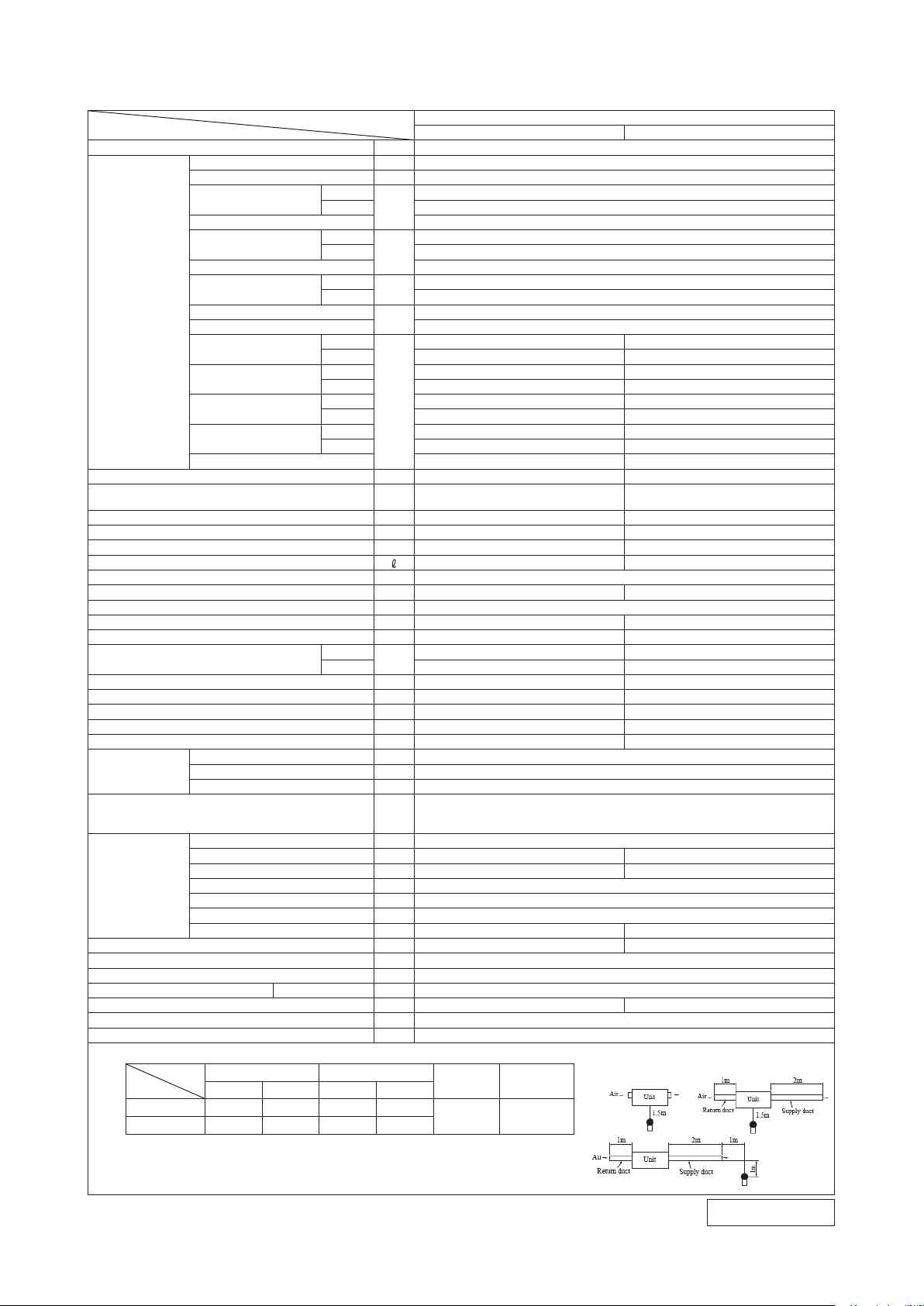
2. EXTERIOR DIMENSIONS
(1) Indoor units
Models SRR25ZM-S, 35ZM-S
RJJ000Z001
750
790(Suspension bolts pitch)
45722 21
500
380
168
105
200
30
326
413
55
660(Outlet dimension)
59
58
165
120
37
99 35
65 65
2020
370
(Suspension bolts pitch)
(Outlet dimension)
600 or less
(Max. drain lift)
50
235〜265
□120 19
660(Inlet dimension)
160 21
65 65
19
(Inlet dimension)
Air Inlet
16
60
24
167
29.57.5
28
68.7
85
101
30
Control box
suspension bolt
Hanger plate for
Air outlet
Connector
(Accessory)
(Installed on site)
F
Inspection hole
(450X450),(320X770)
A
Gas piping
B
Liquid piping
C1
Drain piping
D
Hole for wiring
E
Suspension bolts
(M10)
Symbol
Content
φ6.35(1/4")(Flare)
φ9.52(3/8")(Flare)
Drain piping
C2
(Gravity drainage)
VP25(I.D.25 , O.D.32)
(Used with attached connector)
VP25(I.D.25 , O.D.32)
(Used with attached connector)
φ25 x 2
Unit:mm
Wired-remote control
(Option)
Wireless remote control
Remote control signal receiver
Remote control
signal receiver
(Cord length 1.8m)
Notes(1)The model name label is attached
on the lid of the control box.
(2)It takes the interface kit (SC-BIKN-E)
to connect the wired remote control.
100
450
450
750
200100
750
150 or more
770
or more
or more
100 or more
1000
1000
150 or more
320
Obstacle
View from top side of the unit
Obstacle
Obstacle
Rear-intake
Ceiling-return type
Space for installation and service
F
E
C
2
D
A
C
1
B
-
6
-
'15 • SR-T-185
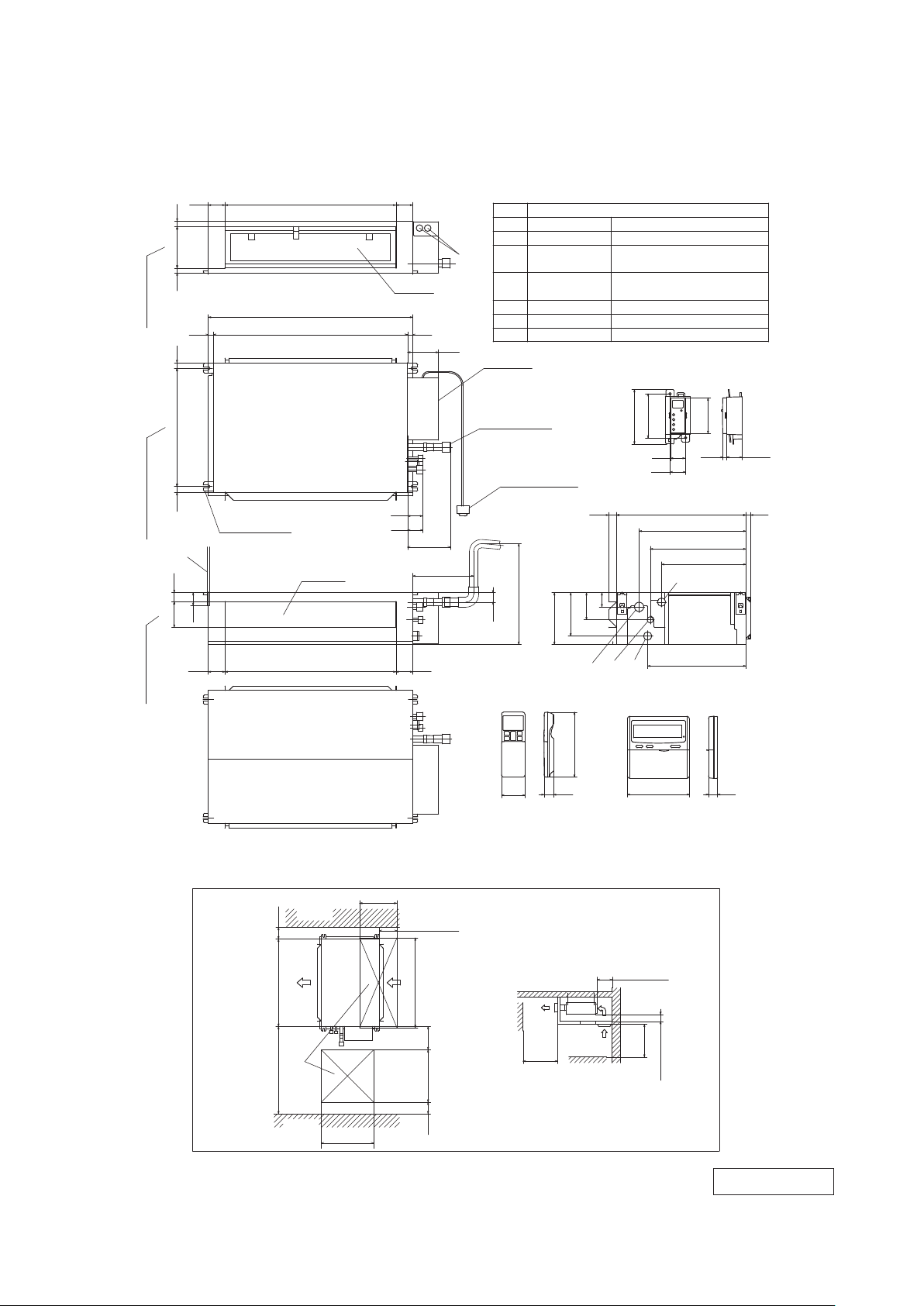
(2) Outdoor units
Models SRC25ZMX-S, 35ZMX-S
( )
φ
9.52(3/8")(Flare)
Content
C
Pipe/cable draw-out hole
E
Anchor bolt hole
Drain discharge hole
Symbol
B
A
Service valve connection(gas side)
M10×4places
φ
20×2places
Service valve connection(liquid side)
φ
6.35(1/4")(Flare)
D
390.6
D
63.4
290
69.4
E
50.6
12
24.3
312.5
351.6
14.8
17.9
61.9
158.4
510
780
390.6
111.6
390.6
595
15.8
97.7
42.5
B
138.4
33.5
C
40°
40
°
A
Terminal block
L2
L3
L4
L1
100
100
250
Open
I II
Open
250
80
280
III
280
Open
80
75
Examples of
Dimensions
installation
IV
180
Open
80
Open
Notes
(1) It must not be surrounded by walls on the four sides.
(2) The unit must be fixed with anchor bolts. An anchor bolt must not
protrude more than 15mm.
(3) Where the unit is subject to strong winds, lay it in such
a direction that the blower outlet faces perpendicularly
to the dominant wind direction.
(4) Leave 1m or more space above the unit.
(5) A wall in front of the blower outlet must not exceed the units height.
(6) The model name label is attached on the lower right corner of the front panel.
Minimum installation space
Unit:mm
L2
Intake
Outlet
Intake
L3
L1
Service
space
L4
RCV000Z020
-
7
-
'15 • SR-T-185
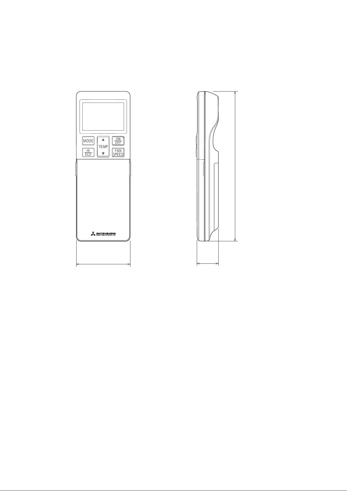
(3) Remote control
Unit : mm
60
26
167
(a) Wireless remote control
-
8
-
'15 • SR-T-185
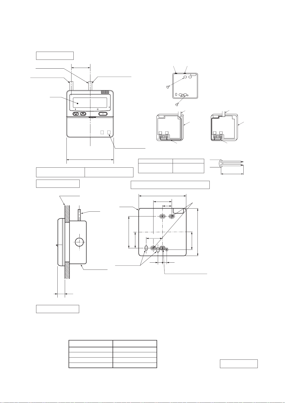
(b) Wired remote control (option parts)
Interface kit (SC-BIKN-E) is required to use the wired remote control.
(i) Model RC-E5
PJZ000Z2 9 5
TEMP ON/OFF
48
□120
L C D
Wall surface
Wiring
Electrical box
(Not included)
19
Wiring specifications
Exposed mounting
23
46
11.5 11
Remote
control
outline
120
45
83.5
42
120
Remote control installation dimensions
Wiring oulet
Installation hole
12×7 Slot hole
9.5×5 Slot hole (4places)
(1) Installation screw for remote control
M4 Screw (2 pieces)
44
(1) If the prolongation is over 100m, change to the size below.
But, wiring in the remote control case should be under 0.5mm2. Change the wire size outside of
the case according to wire connecting. Waterproof treatment is necessary at the wire connecting
section. Be careful about contact failure.
Length Wiring thickness
100 to 200m
0.5mm2×2 cores
0.75mm2×2 cores
1.25mm2×2 cores
2.0mm2×2 cores
Under 300m
Under 400m
Under 600m
Upper part
Lower part
Lower case
Sheath
Upper cace
Board
Wiring
Upper
Lower
X Y
Sheath
Upper cace
Board
Wiring
Upper
Lower
YX
Tighten the screws after
cutting off the thin part of
screw mounting part.
Embedded mounting
Pearl WhiteExterior appearance
(Munsell color) (N8.5) near equivalent
The peeling-off length of sheath
The peeling-off length
of sheath
In case of pulling out from
upper left
In case of pulling out
from upper left
In case of pulling out
from upper left
X wiring : 170mm
Y wiring : 190mm
Pulling out from center
X wiring : 215mm
Y wiring : 195mm
Pulling out from upper left
In case of pulling out from center
In case of pulling out
from center
In case of pulling out
from center
Wiring outlet
Cut off the upper thin part of remote control lower case with a nipper or knife,
and grind burrs with a file etc.
0.3mm2×2 cores.
X, Y Terminal block
Attach M3 screw
with washer
Unit:mm
-
9
-
'15 • SR-T-185
Installation sp
a
ce
R/C
c
abl
e:0
.3mm
2
× 2-co
r
e
A
dapted to R
oHS
directive
Exterior appearance
(Munsell color)
Pearl White
(N8.5) near equivalent
-
A
PJZ000 Z297
(ii) Model RC-EX1A
-
10
-
'15 • SR-T-185
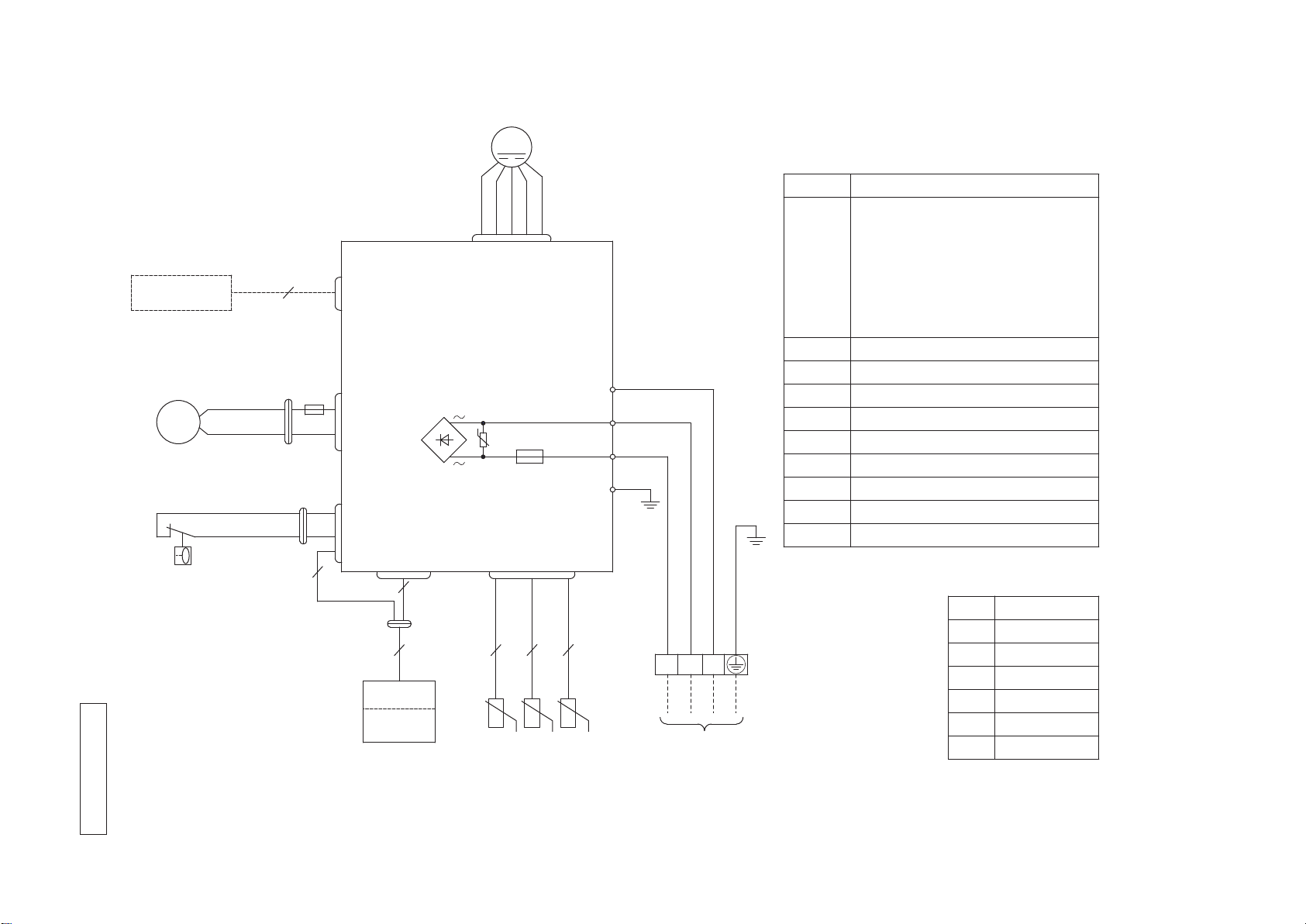
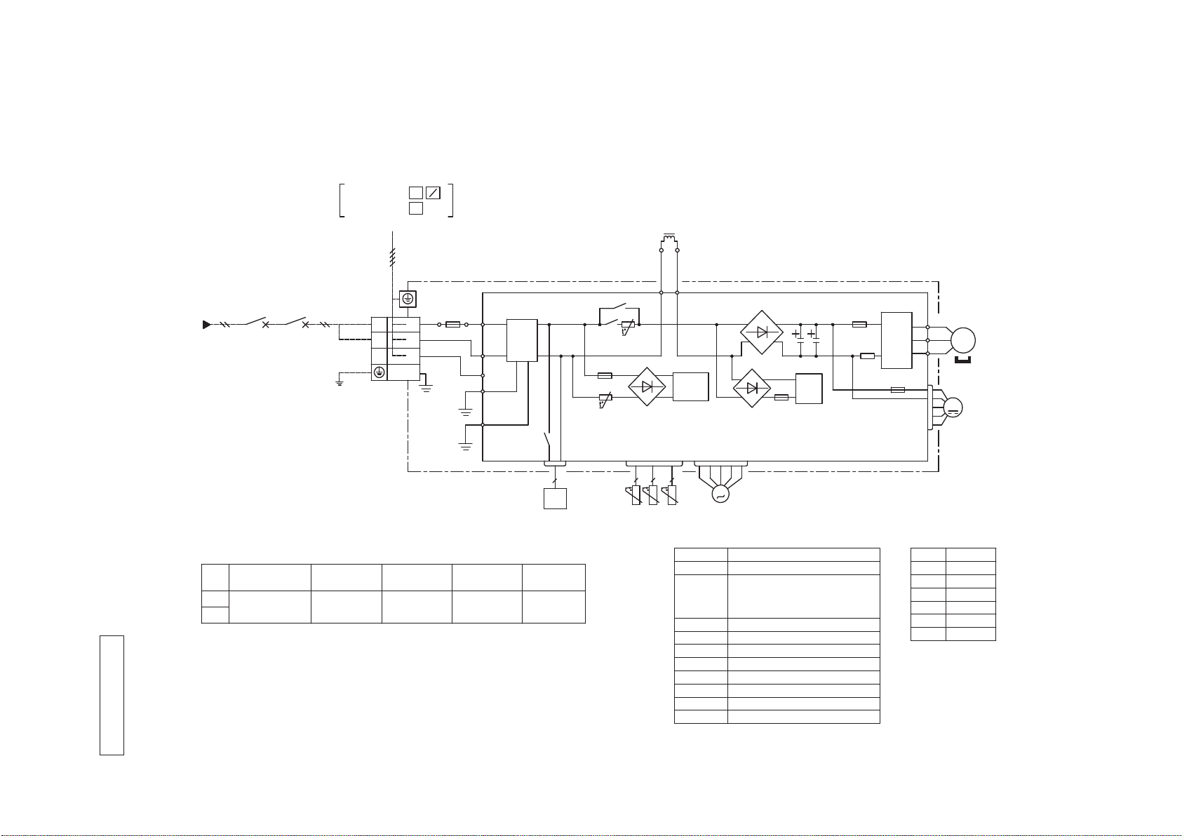
3. ELECTRICAL WIRING
(1) Indoor units
Models SRK25ZM-S, 35ZM-S
RJJ000Z0 0 3
TO OUTDOOR UNIT
RECEIVER
FS
BL
Y
BKRDWH
CNG
DISPLAY
WIRELESS
CNE
BK
BK
PRINTED CIRCUIT
BOARD
CNU
1 3 54 6
G
Y/G
RD
1
2/N
3
WHBKY/G
RD
S/N
J
L
FM
U
10
2
2 2
Y
CNW
DM
DM
F
1
F 0.16A
L 250V
F
2
F 3.15A
L 250V
Y
BK
RD
CNS
゜t゜t゜
t
5
1〜
8
2
RD
TB
CNY
Color Marks
Blue
BlackBK
Red
BL
RD
WhiteWH
YellowY
ColorMark
Heat exchanger sensor
Fan motor
Room temp. sensorTh1
Th2
1,2
Diode stackDS
FuseF
1,2
ConnectorCNE
FM
I
Terminal blockTB
Description
Item
Drain motorDM
CNG
CNS
CNU
CNW
CNY
DS
Va
Th1
Th2
1
Th22
FM
I
Yellow/GreenY/G
Float switchFS
VaristorVa
INTERFACE KIT
SC-BIKN
Power source
1 Phase
220/230/240V 50Hz
-
11
-
'15 • SR-T-185
(2) Outdoor units
Models SRC25ZMX-S, 35ZMX-S
RWC000Z272
Description
Item
Connector
Electric expansion valve(coil)
EEV
Fan motorFMo
ReactorL
Terminal blockTB1
Compressor motorCM
Solenoid valve for 4 way valve20S
Heat exchanger sensor(outdoor unit)
TH2
Outdoor air temp.sensorTH3
TH4 Discharge pipe temp.sensor
CN20S
CNTH
CNEEV
CNFAN
Color
RD
Mark
OrangeOR
Yellow/Green
Y/G
Black
BK
YellowY
WhiteWH
Red
Power cable, indoor-outdoor connecting wires
・The specifications shown in the above table are for units without heaters. For units with heaters, refer
to the installation instructions or the construction instructions of the indoor unit.
・Switchgear of Circuit breaker capacity which is calculated from MAX. over current should be chosen
along the regulations in each country.
・The cable specifications are based on the assumption that a metal or plastic conduit is used with no
more than three cables contained in a conduit and a voltage drop is 2%. For an installation falling
outside of these conditions, please follow the internal cabling regulations. Adapt it to the regulation
in effect in each country.
Model
MAX running current
Power cable size
(mm )
2
(A)
Power cable length
(m)
indoor-outdoor
wire size x number
Earth wire size
25
2.0
32
35
1.5mm x 3
2
8
1.5
(mm )
2
3
1
2
TO INDOOR UNIT
POWER WIRES
SIGNAL WIRE
N
Power source
TB1
TERMINAL
BLOCK
L
N
1
3
2
(BK)
R.IN
250V 15A
(BK)
(WH)
(Y/G)
(Y/G)
(Y/G)
(RD)
C-2
G1
G2
S.IN
FILTER
NOISE
F1
250V 3.15A
T1
T2
(OR)
(Y)
L
20S
2
2 2 2
CN20S CNTH CNEEV
TH2 TH3 TH4
M
EEV
CIRCUIT
POWER
SWITCHING
F4
250V 10A
CIRCUIT
PAM
250V 20A
F2
PCB ASSY PCB1
TRANSISTOR
POWER
(BK)
(WH)
(RD)
N
P
W
V
U
W
V
U
M
3~
CM
F3 250V 1A
CNFAN
FMo
M
1Phase AC 220ー240V 50Hz
-
12
-
'15 • SR-T-185
(Indoor Unit)
Model SRR25ZM-S
Noise
Level
Cooling 37 dB(A)
Heating 40 dB(A)
×
......
Cooling Heating
(Outdoor Unit)
Model SRC25ZMX-S
Noise
Level
Cooling 47 dB(A)
Heating 47 dB(A)
×
......
Cooling Heating
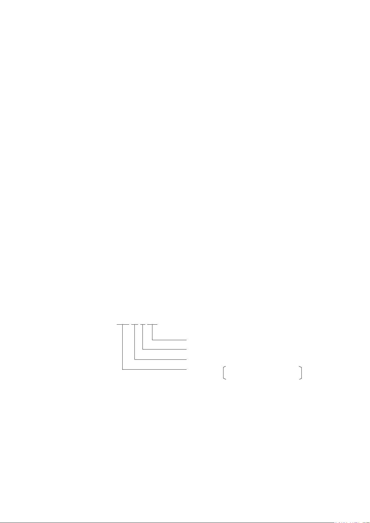
Mike position: at highest noise level in position as mentioned below
Distance from front side 1m
Mike position
0.8m
1m
Unit
Mike position
(Center & Low points)
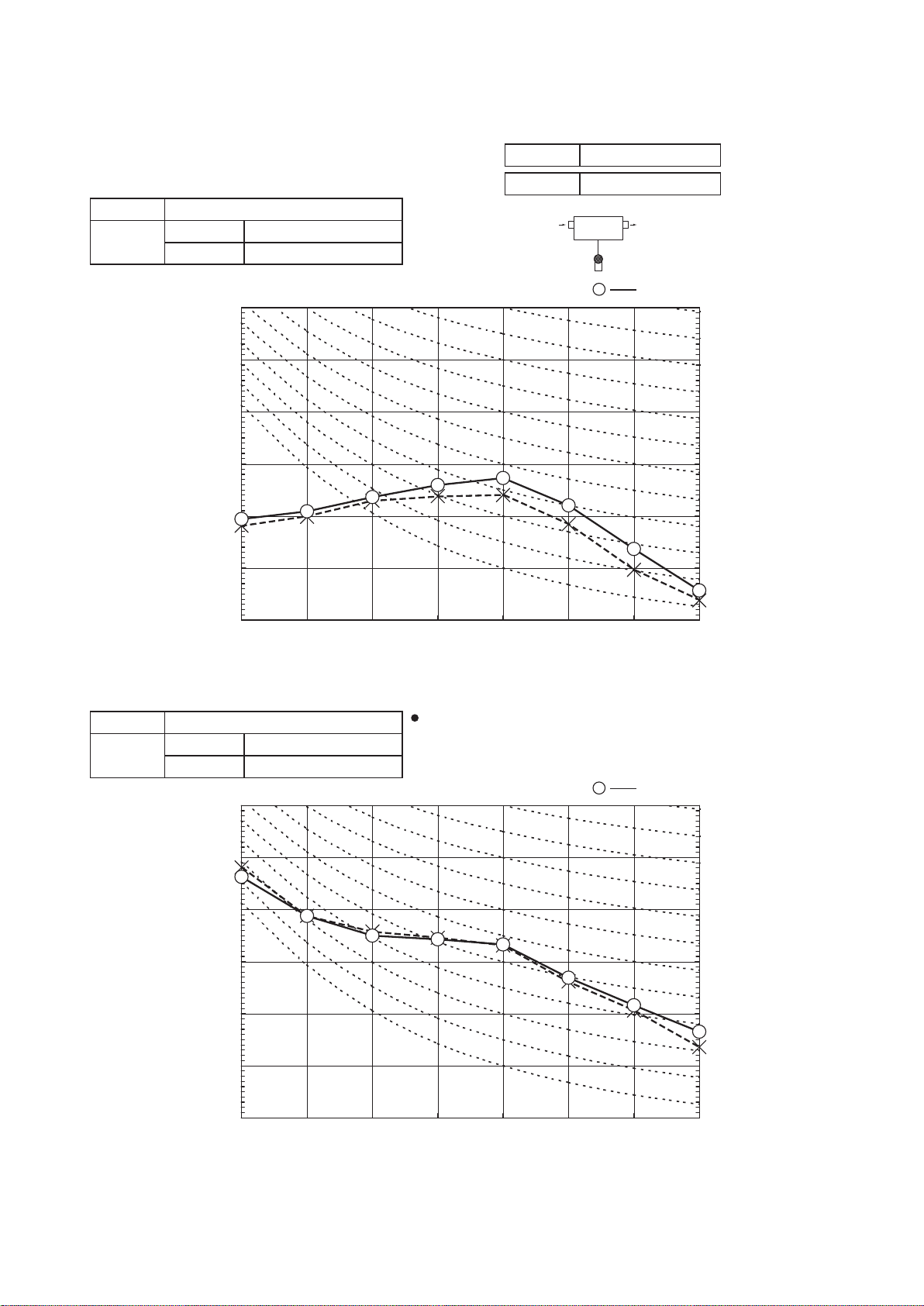
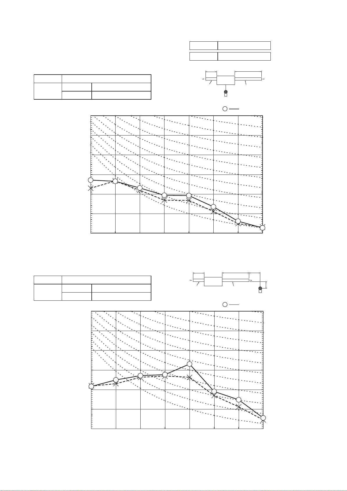
4. NOISE LEVEL
Model SRR25ZM-S
◦Sound pressure level
①
10
20
30
40
50
60
70
63 125 250 500 1000 2000 4000 8000
Mid Octave Band frequency (Hz)
Sound Pressure Level (dB)
(Standard 2×10
-5
P a )
10
20
30
40
50
60
70
N50
N30
N40
N60
N70
N20
●Mike position
1.5m
Unit
Air
Condition
ISO5151 T1,JIS C 9612
MODE Rated capacity value
10
20
30
40
50
60
70
63 125 250 500 1000 2000 4000 8000
Mid Octave Band frequency (Hz)
Sound Pressure Level (dB)
(Standard 2×10
-5
P a )
10
20
30
40
50
60
70
N50
N30
N40
N60
N70
N20
-
13
-
'15 • SR-T-185
(Indoor Unit)
Model SRR25ZM-S
Noise
Level
Cooling 31 dB(A)
Heating 33 dB(A)
×
......
Cooling Heating
(Indoor Unit)
Model SRR25ZM-S
Noise
Level
Cooling 39 dB(A)
Heating 44 dB(A)
×
......
Cooling Heating
◦Sound pressure level
②
10
20
30
40
50
60
70
63 125 250 500 1000 2000 4000 8000
Mid Octave Band frequency (Hz)
Sound Pressure Level (dB)
(Standard 2×10
-5
P a )
10
20
30
40
50
60
70
N50
N30
N40
N60
N70
N20
Condition
ISO5151 T1,JIS C 9612
MODE Rated capacity value
10
20
30
40
50
60
70
63 125 250 500 1000 2000 4000 8000
Mid Octave Band frequency (Hz)
Sound Pressure Level (dB)
(Standard 2×10
-5
P a )
10
20
30
40
50
60
70
N50
N30
N40
N60
N70
N20
1.5m
1m
Unit
Supply duct
Return duct
External staic pressure : 10Pa
●Mike position
2m
Air
◦Sound pressure level
③
1m
Unit
Supply duct
Return duct
2m
1m
1m
Air
External staic pressure : 10Pa
●Mike position
-
14
-
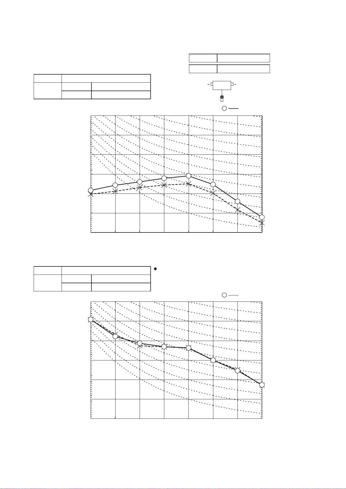
'15 • SR-T-185
(Indoor Unit)
Model SRR35ZM-S
Noise
Level
Cooling 38 dB(A)
Heating 42 dB(A)
×
......
Cooling Heating
(Outdoor Unit)
Model SRC35ZMX-S
Noise
Level
Cooling 50 dB(A)
Heating 50 dB(A)
×
......
Cooling Heating
Mike position: at highest noise level in position as mentioned below
Distance from front side 1m
Mike position
0.8m
1m
Unit
Mike position
(Center & Low points)
Model SRR35ZM-S
◦Sound pressure level
①
10
20
30
40
50
60
70
63 125 250 500 1000 2000 4000 8000
Mid Octave Band frequency (Hz)
Sound Pressure Level (dB)
(Standard 2×10
-5
P a )
10
20
30
40
50
60
70
N50
N30
N40
N60
N70
N20
●Mike position
1.5m
Unit
Air
Condition
ISO5151 T1,JIS C 9612
MODE Rated capacity value
10
20
30
40
50
60
70
63 125 250 500 1000 2000 4000 8000
Mid Octave Band frequency (Hz)
Sound Pressure Level (dB)
(Standard 2×10
-5
P a )
10
20
30
40
50
60
70
N50
N30
N40
N60
N70
N20
-
15
-
'15 • SR-T-185
(Indoor Unit)
Model SRR35ZM-S
Noise
Level
Cooling 33 dB(A)
Heating 34 dB(A)
×
......
Cooling Heating
(Indoor Unit)
Model SRR35ZM-S
Noise
Level
Cooling 40 dB(A)
Heating 45 dB(A)
×
......
Cooling Heating
◦Sound pressure level
②
10
20
30
40
50
60
70
63 125 250 500 1000 2000 4000 8000
Mid Octave Band frequency (Hz)
Sound Pressure Level (dB)
(Standard 2×10
-5
P a )
10
20
30
40
50
60
70
N50
N30
N40
N60
N70
N20
Condition
ISO5151 T1,JIS C 9612
MODE Rated capacity value
10
20
30
40
50
60
70
63 125 250 500 1000 2000 4000 8000
Mid Octave Band frequency (Hz)
Sound Pressure Level (dB)
(Standard 2×10
-5
P a )
10
20
30
40
50
60
70
N50
N30
N40
N60
N70
N20
1.5m
1m
Unit
Supply duct
Return duct
External staic pressure : 10Pa
●Mike position
2m
Air
◦Sound pressure level
③
1m
Unit
Supply duct
Return duct
2m
1m
1m
Air
External staic pressure : 10Pa
●Mike position

-
16
-
'15 • SR-T-185
Models SRK20ZJX-S, 25ZJX-S, 35ZJX-S
Indoor unit
Outdoor unit
Flare
connection
Flare connection
Liquid
pipe
(φ6.35)
Gas pipe
(φ9.52)
Service valve
Heat
exchanger
Heat
exchanger
sensor
Electronic
expansion valve
(Liquid)
Strainer Muffler
Capillary tube
Outdoor air
temp. sensor
Muffler
Muffler
Compressor
Accumulator
Discharge pipe
temp. sensor
Cooling cycle
Heating cycle
Check joint
4way valve
Service valve
Heat
exchanger
sensor
(Th2
2)
(TH3)
Room temp.
sensor
(Th1)
(Th2
1)
(
Gas
)
(TH2)
Heat
exchanger
sensor
(TH1)
(EEV)
Capillary tube
Heat
exchanger
Model SRK50ZJ-S
Indoor unit
Outdoor unit
Flare
connection
Flare connection
Liquid
pipe
(φ6.35)
Gas pipie
(φ12.7)
Service valve
Heat
exchanger
Heat
exchanger
sensor
Electronic
expansion valve
(Liquid)
Strainer
Receiver
Muffler
Capillary tube
Outdoor air
temp. sensor
Muffler
Muffler
Compressor
Discharge pipe
temp. sensor
Cooling cycle
Heating cycle
Check joint
4way valve
Service valve
Heat
exchanger
sensor
(Th3)
(TH3)
Room temp.
sensor
(Th1)
(Th2)
(
Gas
)
(TH2)
Heat
exchanger
sensor
(TH1)
(EEV)
Capillary tube
Heat
exchanger
Models SRR25ZM-S, 35ZM-S
6. PIPING SYSTEM
40
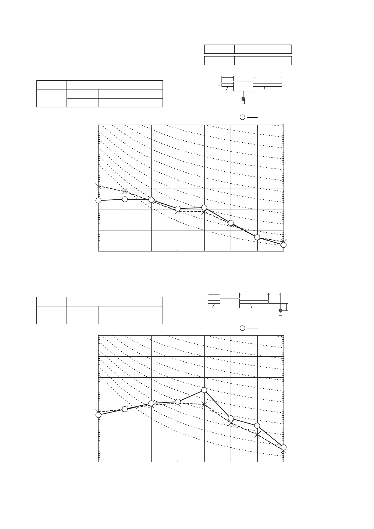
Air flow (m3/min)
External static pressure (Pa)
40
30
20
10
0
4 6 8
Air flow (m3/min)
External static pressure (Pa)
10
40
30
20
10
0
4 6 8
Air flow (m3/min)
External static pressure (Pa)
10
40
30
20
10
0
4 6 8
Air flow (m3/min)
External static pressure (Pa)
10
30
20
10
0
4 6
ULo
Lo
Me
Hi
ULo
Lo
Me
Hi
ULo
Lo
Me
Hi
ULo
Lo
Me
Hi
8 10
Model SRR25ZM-S
Cooling Heating
Model SRR35ZM-S
Cooling Heating
5. CHARACTERISTICS OF FAN
-
17
-
'15 • SR-T-185
RANGE OF USAGE & LIMITATIONS
Indoor return air temperature
(Upper, lower limits)
Refrigerant line (one way) length
Power source voltage Rating ±10%
Voltage at starting Min. 85% of rating
Frequency of ON-OFF cycle
Max. 4 times/h
(Inching prevention 10 minutes)
ON and OFF interval Min. 3 minutes
Outdoor air temperature
(Upper, lower limits)
Vertical height difference between
outdoor unit and indoor unit
Max. 15m
Max. 10m
(Outdoor unit is higher)
Max. 10m
(Outdoor unit is lower)
Item
Model
SRR25ZM-S, 35ZM-S
Cooling operation : Approximately 18 to 32℃ D.B.
Heating operation : Approximately 10 to 30℃ D.B.
(Refer to the selection chart)
Cooling operation : Approximately -15 to 46℃ D.B.
Heating operation : Approximately -15 to 24℃ D.B.
(Refer to the selection chart)
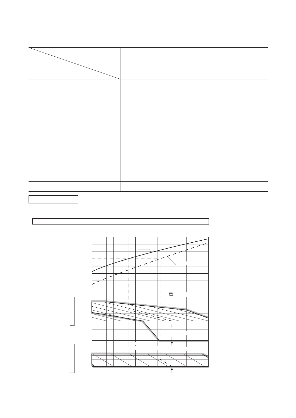
Selection chart
Correct the cooling and heating capacity in accordance with the conditions as follows. The net cooling and heating capacity can be
obtained in the following way.
Net capacity = Capacity shown on specification ×Correction factors as follows.
(1) Coefficient of cooling and heating capacity in relation to temperatures
0.6
0.7
0.8
0.9
1.0
1.2
1.1
1.3
0
-5
-10
-15
24
26
20
25
30
35
40
46
10
15
20
25
27
Outdoor air W.B. temperature °C W.B.
-15 -10 -5 0 5 10 15
.
Cooling operation
Outdoor air D.B.
temperature
°C D. B.
Coefficient of cooling
&
heating capacity in
relation to temperature
Heating operation
Indoor air D.B.
temperature
°C D. B.
ISO-T1 Standard Condition
Depends on installed situation
ISO-T1 Standard Condition
2220181614
Indoor air W.B. temperature °C W.B
Applicable range
Cooling
Heating
7. RANGE OF USAGE & LIMITATIONS
-
18
-
'15 • SR-T-185
'09•SRK-DB-087D
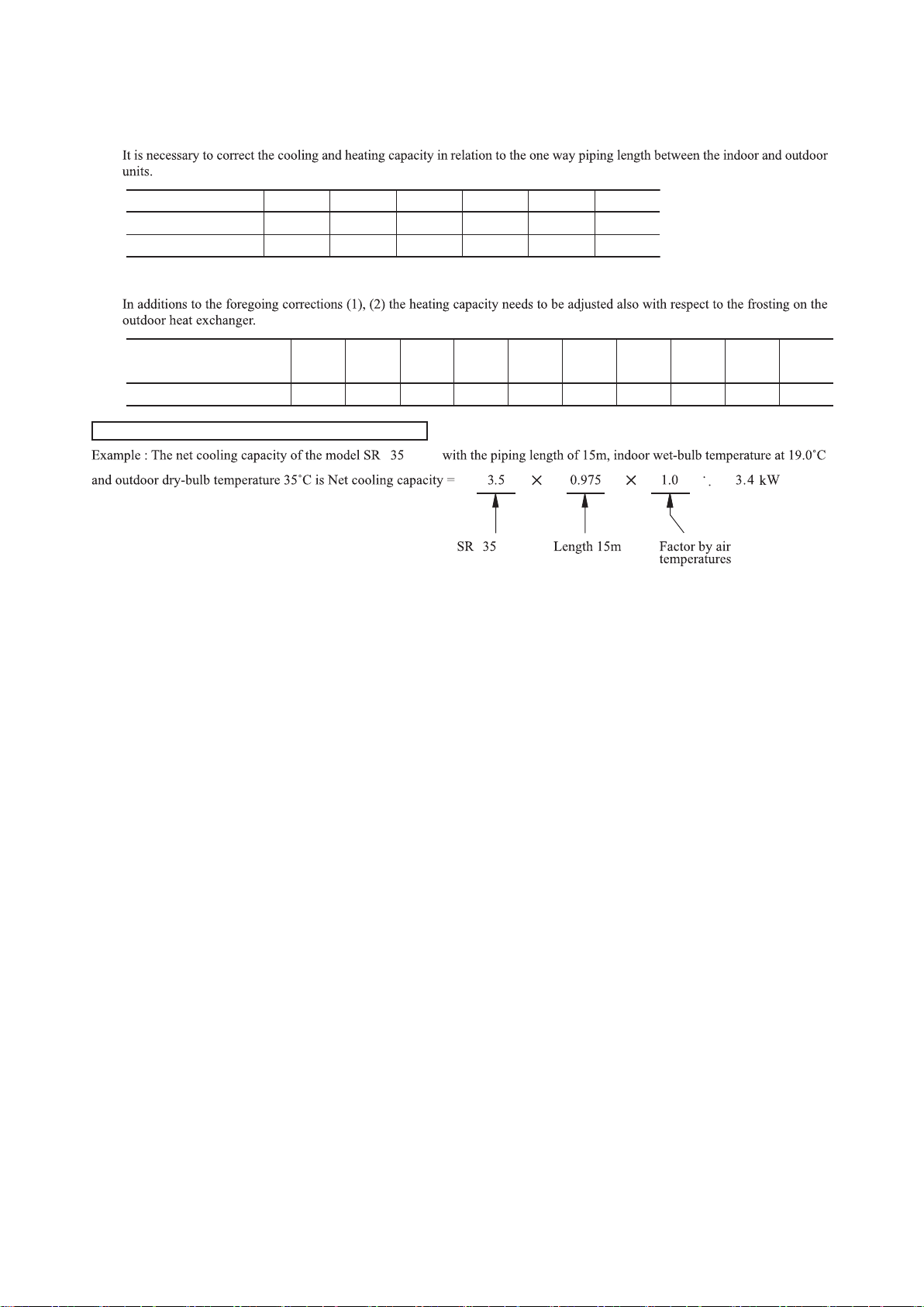
(2) Correction of cooling and heating capacity in relation to one way length of refrigerant piping
(3) Correction relative to frosting on outdoor heat exchanger during heating
How to obtain the cooling and heating capacity
=
Piping length [m]
Cooling
Heating
7
1.0
1.0
10
0.99
1.0
15
0.975
1.0
20
0.965
1.0
25
0.95
1.0
30
0.935
1.0
Air inlet temperature of
outdoor unit in °C WB
Adjustment coefficient
-15
0.95 0.95 0.94 0.93 0.91 0.88 0.86 0.87 0.92 1.00
-10 -9 -7 -5 -3 -1 1 3
5 or more
ZM-S
ZM-S
R
R
-
19
-
'15 • SR-T-185
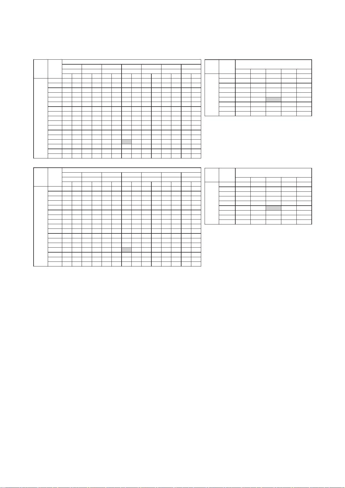
8. CAPACITY TABLES
2.58 2.53 2.47 2.42 2.36
3.48 3.44 3.40 3.36 3.32
4.30 4.25 4.20 4.15 4.10
35 2.91 2.49 3.10 2.47 3.37 2.66 3.50 2.65 3.58 2.63 3.80 2.76 3.96 2.71
35 2.08 1.97 2.21 1.99 2.41 2.15 2.50 2.15 2.56 2.13 2.71 2.26 2.83 2.22
Hi 22 2.49 2.20 2.63 2.18 2.78 2.30 2.84 2.29 2.90 2.26 3.02 2.37 3.13 2.32
Air flow
Hi 22 3.49 2.78 3.68 2.74 3.89 2.88 3.98 2.85 4.06 2.82 4.23 2.93 4.38 2.85
edoMtingtaeH(kW)
(kW)
(kW)
(kW)
Cooling Mode
Cooling Mode
℃DB
23
℃DB
26
℃DB
27
℃DB
28
℃DB
31
℃DB
33
℃DB
Outdoor
air temp.
℃WB
16
℃WB
18
℃WB
19
℃WB
20
℃WB
22 ℃WB 24 ℃WB
61
CHSCTCHSCTCHSCTCHSCTCHSCTCHSCTCHSCT
℃ DB 18℃ DB 20℃ DB 22℃ DB 24℃ DB
10 2.82 2.35 2.95 2.32 3.06 2.42 3.11 2.39 3.16 2.36 3.26 2.45 3.34 2.39
2.09 2.05 2.00 1.96 1.91
12 2.77 2.33 2.90 2.29 3.01 2.40 3.07 2.38 3.12 2.35 3.22 2.44 3.31 2.37
2.37 2.33 2.29 2.24 2.19
14 2.71 2.30 2.85 2.27 2.97 2.39 3.03 2.36 3.08 2.33 3.18 2.43 3.28 2.36
2.56 2.53 2.48 2.45 2.41
16 2.66 2.28 2.80 2.24 2.92 2.36 2.98 2.34 3.04 2.32 3.15 2.42 3.24 2.35
2.69 2.65 2.60 2.57 2.53
18 2.60 2.25 2.74 2.22 2.88 2.35 2.94 2.33 2.99 2.30 3.11 2.40 3.20 2.34
3.42 3.38 3.37 3.3
0 3.25
20 2.55 2.23 2.68 2.20 2.83 2.32 2.89 2.30 2.95 2.28 3.07 2.39 3.17 2.33
(
m
3
/
min
)
6
3.70 3.66 3.64 3.59 3.55
9.5 24 2.43 2.17 2.57 2.15 2.72 2.28 2.80 2.26 2.85 2.24 2.98 2.36 3.08 2.30
4.02 3.99 3.96 3.92 3.88
(
m3/min
)
26 2.37 2.14 2.51 2.12 2.67 2.26 2.74 2.25 2.80 2.23 2.93 2.34 3.04 2.29
4.32 4.29 4.27 4.22 4.19
28 2.31 2.11 2.44 2.09 2.61 2.24 2.69 2.23 2.75 2.21 2.89 2.33 3.00 2.27
30 2.24 2.08 2.38 2.06 2.56 2.21 2.64 2.20 2.70 2.18 2.84 2.31 2.95 2.26
32 2.18 2.05 2.31 2.04 2.50 2.18 2.58 2.18 2.64 2.16 2.79 2.29 2.90 2.25
34 2.11 2.00 2.25 2.01 2.44 2.16 2.53 2.16 2.59 2.14 2.74 2.27 2.85 2.23
36 2.04 1.94 2.18 1.98 2.38 2.14 2.47 2.14 2.53 2.12 2.69 2.25 2.80 2.22
38 1.97 1.87 2.11 1.95 2.32 2.12 2.41 2.12 2.47 2.10 2.63 2.24 2.75 2.20
39 1.94 1.84 2.07 1.93 2.28 2.11 2.38 2.11 2.44 2.09 2.61 2.23 2.72 2.19
Outdoor
℃DB 23
℃DB
26
℃DB
27 ℃DB 28
℃DB
31
℃DB 33 ℃DB
Outdoor
air temp.
air temp.
℃WB
16
℃WB
18
℃WB
19
℃WB 20 ℃WB 22 ℃WB 24 ℃WB
Air flow
61
CHSCTCHSCTCHSCTCHSCTCHSCTCHSCTCHSCT
℃ DB 18℃ DB 20℃ DB 22℃ DB 24℃ DB
10 3.94 3.01 4.13 2.96 4.28 3.06 4.35 3.02 4.43 2.98 4.56 3.05 4.68 2.94
12 3.87 2.97 4.06 2.93 4.22 3.03 4.29 2.99 4.37 2.95 4.51
3.02 4.63 2.93
2.92 2.87 2.83 2.76 2.70
14 3.80 2.94 3.99 2.89 4.16 3.00 4.24 2.97 4.31 2.93 4.46 3.00 4.59 2.92
3.17 3.12 3.06 3.02 2.97
16 3.72 2.90 3.91 2.85 4.09 2.97 4.18 2.94 4.25 2.90 4.40 2.98 4.54 2.90
3.32 3.27 3.21 3.18 3.13
18 3.65 2.86 3.84 2.82 4.03 2.94 4.11 2.91 4.19 2.87 4.35 2.97 4.49 2.89
4.23 4.18 4.16 4.07 4.02
20 3.57 2.82 3.76 2.78 3.96 2.91 4.05 2.88 4.13 2.85 4.29 2.95 4.43 2.87
4.57 4.52 4.49 4.43 4.39
10.0 24 3.40 2.73 3.59 2.70 3.81 2.85 3.91 2.83 3.99 2.80 4.17 2.90 4.32 2.83
4.97 4.93 4.89 4.84 4.79
(
m
3
/min
)
26 3.32 2.69 3.51 2.66 3.74 2.81 3.84 2.79 3.92 2.76 4.11 2.88 4.26 2.81
5.34 5.30 5.27 5.21 5.17
28 3.23 2.65 3.42 2.62 3.66 2.77 3.77 2.76 3.85 2.73 4.04 2.85 4.20 2.79
30 3.14 2.60 3.33 2.58 3.58 2.74 3.70 2.73 3.78 2.70 3.98 2.83 4.13 2.76
32 3.05 2.55 3.24 2.53 3.50 2.71 3.62 2.70 3.70 2.68 3.91 2.80 4.06 2.74
34 2.95 2.51 3.14 2.49 3.41 2.67 3.54 2.67 3.62 2.64 3.84 2.78 4.00 2.72
36 2.86 2.47 3.05 2.45 3.33 2.64 3.46 2.64 3.54 2.61 3.76 2.75 3.92 2.70
38 2.76 2.42 2.95 2.40 3.24 2.60 3.38 2.60 3.46 2.58 3.69 2.73 3.85 2.67
39 2.71 2.39 2.90 2.38 3.20 2.58 3.33 2.59 3.42 2.57 3.65 2.71 3.81 2.66
Indoor air temp.
Indoor air temp.
-15
-10
-5
Hi
10.0
10
15
20
6
-15
-10
-5
Hi
10.0
10
15
20
Model SRR25ZM-S
Model SRR35ZM-S
Indoor air temp.
Indoor air temp.
(
m
3
/
min
)
edoMtingtaeH
(℃WB)
5
0
(℃WB)
5
0
14
21
(℃DB)
Air flow
Outdoor
air temp.
14
21
(℃DB)
Air flow
Note(1) These data show average statuses.
Depending on the system control, there may be ranges where the operation is
not conducted continuously.
These data show the case where the operation frequency of a compressor is
fixed.
(2) Capacities are based on the following conditions.
Corresponding refrigerant piping length :7m
Level difference of Zero.
(3) Symbols are as follows.
TC : Total cooling capacity (kW)
SHC : Sensible heat capacity (kW)
HC : Heating capacity (kW)
-
20
-
'15 • SR-T-185
R410A REFRIGERANT USED
FOR MODEL SRR SERIES
INSTALLATION MANUAL FOR INDOOR UNIT
RJJ012A002
WARNING
• Installation must be carried out by the qualified installer.
If you install the system by yourself, it may cause serious trouble such as
water leaks, electric shocks, fire and personal injury, as a result of a
system malfunction. Do not carry out the installation and maintenance
work except the by qualified installer.
• Install the system in full accordance with the installation manual.
Incorrect installation may cause bursts, personal injury, water leaks,
electric shocks and fire.
• Be sure to use only for household and residence.
If this appliance is installed in inferior environment such as machine shop
and etc., it can cause malfunction.
• Use the original accessories and the specified components for
installation.
If parts other than those prescribed by us are used, It may cause water
leaks, electric shocks, fire and personal injury.
• Install the unit in a location with good support.
Unsuitable installation locations can cause the unit to fall resulting in
material damage and personal injury.
• Ventilate the working area well in the event of refrigerant leakage
during installation.
If the refrigerant comes into contact with naked flames, poisonous gas is
produced.
• When installing in small rooms, take prevention measures not to
exceed the density limit of refrigerant in the event of leakage,
referred by the formula (accordance with ISO5149).
If the density of refrigerant exceeds the limit, consult the dealer and
install the ventilation system, otherwise lack of oxygen can occur, which
can cause serious accident.
• After completing installation, check that no refrigerant leaks from
the system.
If refrigerant leaks into the room and comes into contact with an oven or
other hot surface, poisonous gas is produced.
• Use the prescribed pipes, flare nuts and tools for R410A.
Using existing parts (for R22 or R407C) can cause the unit failure and
serious accidents due to burst of the refrigerant circuit.
• Tighten the flare nut by torque wrench with specified method.
If the flare nuts were tightened with excess torque, this may cause burst
and refrigerant leakage after a long period.
• The electrical installation must be carried out by the qualified
electrician in accordance with “the norm for electrical work” and
“national wiring regulation”, and the system must be connected to
the dedicated circuit.
Power source with insufficient capacity and incorrect function done by
improper work can cause electric shocks and fire.
• Be sure to shut off the power before starting electrical work.
Failure to shut off the power can cause electric shocks, unit failure or
incorrect function of equipment.
• Be sure to use the cables conformed to safety standard and cable
ampacity for power distribution work.
Unconformable cables can cause electric leak, anomalous heat
production or fire.
• This appliance must be connected to main power source by means
of a circuit breaker or switch (fuse:16A) with a contact separation of
at least 3mm.
• When plugging this appliance, a plug conforming to the norm
IEC60884-1 must be used.
• Use the prescribed cables for electrical connection, tighten the
cables securely in terminal block and relieve the cables correctly to
prevent overloading the terminal blocks.
Loose connections or cable mountings can cause anomalous heat
production or fire.
• Arrange the wiring in the control box so that it cannot be pushed up
further into the box. Install the service panel correctly.
Incorrect installation may result in overheating and fire.
• Be sure to switch off the power source in the event of installation,
inspection or servicing.
If the power source is not shut off, there is a risk of electric shocks, unit
failure or personal injury due to the unexpected start of fan.
• Be sure to wear protective goggles and gloves while at work.
• Earth leakage breaker must be installed.
If the earth leakage breaker is not installed, it can cause electric shocks.
CAUTION
• Use the circuit breaker of correct capacity. Circuit breaker should
be able to disconnect all poles under over current.
Using the incorrect one could cause the system failure and fire.
• Install isolator or disconnect switch on the power source wiring in
accordance with the local codes and regulations.
The isolator should be locked in OFF state in accordance with
EN60204-1.
• Be sure to install indoor unit properly according to instruction
manual so that drainage can run off smoothly.
Improper installation of indoor unit can cause dropping water into the
room and damaging personal property.
• Install the drainage pipe to run off drainage securely according to
the installation manual.
Incorrect installation of the drainage pipe can cause dropping water into
the room and damaging personal property.
• Be sure to install the drainage pipe with descending slope of 1/100
or more, and not to make traps and air-bleedings.
Check if the drainage runs off securely during commissioning and ensure
the space for inspection and maintenance.
• After maintenance, all wiring, wiring ties and the like, should be
returned to their original state and wiring route, and the necessary
clearance from all metal parts should be secured.
• Secure a space for installation, inspection and maintenance
specified in the manual.
Insufficient space can result in accident such as personal injury due to
falling from the installation place.
• Take care when carrying the unit by hand.
If the unit weights more than 20kg, it must be carried by two or more
persons. Do not carry by the plastic straps, always use the carry handle
when carrying the unit by hand. Use gloves to minimize the risk of cuts
by the aluminum fins.
• Dispose of any packing materials correctly.
Any remaining packing materials can cause personal injury as it contains
nails and wood. And to avoid danger of suffocation, be sure to keep the
plastic wrapper away from children and to dispose after tear it up.
• For installation work, be careful not to get injured with the heat
exchanger, piping flare portion or screws etc.
• Be sure to insulate the refrigerant pipes so as not to condense the
ambient air moisture on them.
Insufficient insulation can cause condensation, which can lead to
moisture damage on the ceiling, floor, furniture and any other valuables.
• When perform the air-conditioner operation (cooling or drying
operation) in which ventilator is installed in the room. In this case,
using the air-conditioner in parallel with the ventilator, there is the
possibility that drain water may backflow in accordance with the
room lapse into the negative pressure status. Therefore, set up the
opening port such as incorporate the air into the room that may
appropriate to ventilation (For example; Open the door a little). In
addition, just as above, so set up the opening port if the room lapse
into negative pressure status due to register of the wind for the high
rise apartment etc.
• Be sure to perform air tightness test by pressurizing with nitrogen
gas after completed refrigerant piping work.
If the density of refrigerant exceeds the limit in the event of refrigerant
leakage in the small room, lack of oxygen can occur, which can cause
serious accidents.
• Do not install the unit in the locations listed below.
• Locations where carbon fiber, metal powder or any powder is floating.
• Locations where any substances that can affect the unit such as sulphide
gas, chloride gas, acid and alkaline can occur.
• Vehicles and ships.
• Locations where cosmetic or special sprays are often used.
• Locations with direct exposure of oil mist and steam such as kitchen and
machine plant.
• Locations where any machines which generate high frequency harmonics
are used.
• Locations with salty atmospheres such as coastlines.
• Locations with heavy snow (If installed, be sure to provide base flame and
snow hood mentioned in the manual).
• Locations where the unit is exposed to chimney smoke.
• Locations at high altitude (more than 1000m high).
• Locations with ammonic atmospheres (e.g. organic fertilizer).
• Locations with calcium chloride (e.g. snow melting agent).
• Locations where heat radiation from other heat source can affect the unit.
• Locations without good air circulation.
• Locations with any obstacles which can prevent inlet and outlet air of the unit.
• Locations where short circuit of air can occur (in case of multiple units
installation).
• Locations where strong air blows against the air outlet of outdoor unit.
• Locations where something located above the unit could fall.
It can cause remarkable decrease in performance, corrosion and damage of
components, malfunction and fire.
• Do not install the indoor unit in the locations listed below (Be sure to
install the indoor unit according to the installation manual for each
model because each indoor unit has each limitation).
• Locations with any obstacles which can prevent inlet and outlet air of the
unit.
• Locations where vibration can be amplified due to insufficient strength of
structure.
• Locations where the infrared receiver is exposed to the direct sunlight or
the strong light beam (in case of the infrared specification unit).
• Locations where an equipment affected by high harmonics is placed (TV
set or radio receiver is placed within 1m).
• Locations where drainage cannot run off safely.
It can affect performance or function and etc.
• Do not install the unit near the location where leakage of
combustible
gases can occur.
If leaked gases accumulate around the unit, it can cause fire.
• Do not install the unit where corrosive gas (such as sulfurous acid
gas etc.) or combustible gas (such as thinner and petroleum gases)
can accumulate or collect, or where volatile combustible substances
are handled.
Corrosive gas can cause corrosion of heat exchanger, breakage of plastic
parts and etc. And combustible gas can cause fire.
• Do not use the indoor unit at the place where water splashes may
occur such as in laundries.
Since the indoor unit is not waterproof, it can cause electric shocks and fire.
• Do not install nor use the system close to the equipment that
generates electromagnetic fields or high frequency harmonics.
Equipment such as inverters, standby generators, medical high frequency
equipments and telecommunication equipments can affect the system, and
cause malfunctions and breakdowns. The system can also affect medical
equipment and telecommunication equipment, and obstruct its function or
cause jamming.
• Do not place any variables which will be damaged by getting wet
under the indoor unit.
When the relative humidity is higher than 80% or drainage pipe is clogged,
condensation or drainage water can drop and it can cause the damage of
valuables.
• Do not install the remote control at the direct sunlight.
It can cause malfunction or deformation of the remote control.
• Do not use the unit for special purposes such as storing foods,
cooling precision instruments and preservation of animals, plants or
art.
It can cause the damage of the items.
• Do not use any materials other than a fuse with the correct rating in
the location where fuses are to be used.
Connecting the circuit with copper wire or other metal thread can cause unit
failure and fire.
• Do not touch any buttons with wet hands.
It can cause electric shocks.
• Do not touch any refrigerant pipes with your hands when the system
is in operation.
During operation the refrigerant pipes become extremely hot or extremely
cold depending the operating condition, and it can cause burn injury or frost
injury.
• Do not wash the inside of the air-conditioner.
Water leakage and permanent damage may result.
Electrical hazard exists.
• Carry out the electrical work for ground lead with care.
Do not connect the ground lead to the gas line, water line, lightning conductor or telephone line’s ground lead. Incorrect grounding can cause unit
faults such as electric shocks due to short-circuiting.
• Do not put the drainage pipe directly into drainage channels where
poisonous gases such as sulphide gas can occur.
Poisonous gases will flow into the room through drainage pipe and
seriously affect the user’s health and safety. This can also cause the
corrosion of the indoor unit and a resultant unit failure or refrigerant leak.
• Ensure that no air enters in the refrigerant circuit when the unit is
installed and removed.
If air enters in the refrigerant circuit, the pressure in the refrigerant circuit
becomes too high, which can cause burst and personal injury.
• Do not process or splice the power cord, or share the socket with
other power plugs.
This may cause fire or electric shock due to defecting contact, defecting
insulation and over-current etc.
• Do not bundle or wind or process the power cord. Do not deform
the power cord by treading it.
This may cause fire or heating.
• Do not vent R410A into the atmosphere : R410A is a fluorinated
greenhouse gas, covered by the Kyoto Protocol with Groval
Warming Potential (GWP)=1975.
• Do not run the unit with removed panels or protections.
Touching rotating equipments, hot surfaces or high voltage parts can
cause personal injury due to entrapment, burn or electric shocks.
• Do not perform any change of protective device itself or its setup
condition.
The forced operation by short-circuiting protective device of pressure
switch and temperature controller or the use of non specified component
can cause fire or burst.
SAFETY PRECAUTIONS
• Before installation, read the “SAFETY PRECAUTIONS” carefully and strictly
follow it during the installation work in order to protect yourself.
• The precautionary items mentioned below are distinguished into two levels,
and .
: Wrong installation would cause serious consequences such
as injuries or death.
: Wrong installation might cause serious consequences
depending on circumstances.
Both mention the important items to protect your health and safety so strictly
follow them by any means.
•
Be sure to confirm no anomaly on the equipment by commissioning after completed
installation and explain the operating methods as well as the maintenance methods
of this equipment to the user according to the owner’s manual.
• Keep the installation manual together with owner ’s manual at a place where
any user can read at any time. Moreover if necessary, ask to hand them to a
new user.
• Before starting the installation work, proper precautions (using suitable
protective clothing, groves etc.) should be taken by qualified installer.
• Pay attention not to fall down the tools, etc. when installing the unit at the
high position.
• If unusual noise can be heard during operation, consult the dealer.
• The meanings of “Marks” used here are shown as follows:
Never do it under any
circumstances.
Always do it according to the
instruction.
CAUTION
WARNING
CAUTION
WARNING
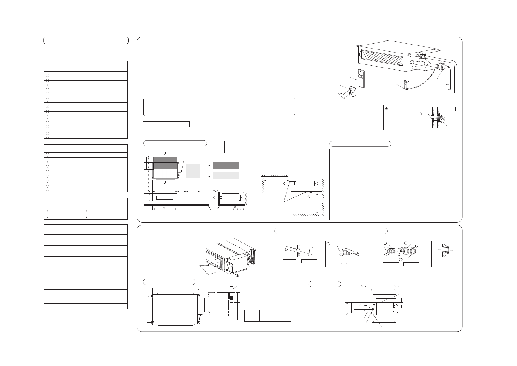
• This installation manual illustrates the method of installing an indoor unit.
• For electrical wiring work, see instructions set out on the backside.
• For outdoor unit installation and refrigerant piping, refer to page24.
• A wired remote control unit is supplied separately as an optional part.
• While installing the unit, be sure to check the selection of installation place,
power source specifications, usage limitation (piping length, height
differences between indoor and outdoor units, power source voltage etc.)
and installation spaces.
9. APPLICATION DATA
(1) Installation of indoor unit
-
21
-
'15 • SR-T-185
Check before installation work
1
1
2
2
1
Q’ty
Standard accessories (installation kit)
Accessories for indoor unit
Wireless remote control
Remote control holder
Battery [R03 (AAA, Micro) 1.5V]
Joint (for drain hose)
2
8
2
4
Washer (for suspension bolt M10)
2
Flat head machine screw
(for remote control signal receiver M3.5x10)
1
Plate (display)
Clamp (for drain hose) (big:1, small:1)
Wood screws
(for remote control holder ø3.5 X 16mm)
• Model name and power source
• Refrigerant piping length
• Piping, wiring and miscellaneous small parts
10
9
8
Band
Pipe cover (big:1, small:1)
13
12
7
6
5
2
1Remote control signal receiver
3
1
Installation frame (for remote control signal receiver)
4
1
Necessary tools for the installation work
1
2
3
4
5
6
7
8
9
Plus headed driver
Knife
Saw
Tape measure
Hammer
Spanner wrench
Torque wrench [14.0~62.0N·m (1.4~6.2kgf·m)]
Hole core drill (65mm in diameter)
Wrench key (Hexagon) [4m/m]
10 Flaring tool set (Designed specifically for R410A)
11 Gas leak detector (Designed specifically for R410A)
12
Gauge for projection adjustment (Used when flare is
made by using conventional flare tool)
13 Pipe bender
1
Q’ty
Option parts (Separately sold parts)
Bottom air inlet kit
25, 35 models : UT-BAT1EF
50, 60 models : UT-BAT2EF
Q’ty
Locally procured parts
1
4
8
4
Drain hose (VP25)
Suspension bolts (M10)
Nuts (M10)
Spring lock washers (M10)
H
G
F
E
1
1
1
1
Sealing plate
Sleeve
Inclination plate
Putty
D
C
B
A
11
When drilling the wall that contains a metal lath, wire lath or metal plate, be sure to use pipe hole sleeve sold separately.
Drilling of hole and fixture of sleeve (Locally procured parts)
Top
Sleeve
Thickness of the
wall + 1.5cm
Indoor side Outdoor side
5
ø65
Indoor side Outdoor side
Installed state
Turn to
tighten
B
C
* Sleeve is for use in refrigerant piping work. Please install another pipe separately for drain piping work.
In case of rear piping draw out, cut off the lower
and the right side portions of the sleeve collar.
Drill a hole with whole core drill.
※Dimensions of the opening on the ceiling after removing inspection opening (1)
Model
25, 35
50, 60
A
750
950
B
770
970
C
100(80)
or more
D
150(50)
or more
E
270
or more
F
150(0)
or more
D
Dedicated
inspection opening
must be provided.
Inspection opening (1)
Inspection opening (2)
Indoor Unit
Ceiling plate
Air intake direction
E F
unit : mm
1000 or more
unit : mm
Obstacle
1000 or more
Obstacle
Pipe locations
All models
Suspension Bolt Location
A
B
Model
25, 35
50, 60
A
790
990
B
457
457
○ Adhere to the measurements given
below for the length of the suspension
bolts.
Unit
Suspension bolt (M10)
Under 60 mm
Remove bracket
in this direction.
Inspection opening (1)Service Inspection opening (2)
Clamping of the flare of required and
gas refrigerant pipe
UseNot Use
Drain pipe connection
UseNot Use
Installation and removal of blower
Not UseUse
Control box
Connecting wire (between indoor and
outdoor)
UseNot Use
Unit display section (Remote control
signal receiver)
UseNot Use
Replace drain pump
UseNot Use
Replace heat exch sensor
UseNot Use
Replace air filter
Not UseUse
Refrigerant gas pipe
Refrigerant liquid pipe
Drain Pipe connection
VP25 (I.D. 25, O.D. 32)
500
413
370
326
380
200
168
105
55
3030
Gravity drainage
The minimum dimensions when used Bottom
air inlet kit (Option parts) are shown in
parentheses.
① Wireless remote control
② Remote control holder
⑤ Wood screws
Sleeve
(Locally procured
parts)
③ Remote control
signal receiver
450
○ Remove bracket from the unit after
unpacking according to process as shown
below.
(1) Loosen 2 screws.
(2) Remove bracket.
(3) Tighten the screws.
Sleeve
Inclination plate
A
Sealing plate
B
Drain pipe, refrigerant gas pipe
and refrigerant liquid pipe
A
200C
200
Air blowout direction
Air outlet
100
450
B
F
E
Screw
CAUTION
Completely seal the hole on
the wall with putty. Otherwise,
furniture, or other, may be
wetted by leaked water or
dewing.
putty
putty
Indoor side Outdoor side
D
D
Grill (Prepare on site)
37
SELECTION OF INSTALLATION LOCATION
INSTALLATION OF INDOOR UNIT
Indoor unit
(Install at location that meets the following conditions, after getting approval from the customer)
○ Where there is no obstructions to the air flow and where the cooled and heated air can be evenly distributed.
○ A firm location that may sustain the weight of the unit, and do not cause the unit or the ceiling to vibrate.
○ A place where there will be enough space for servicing. (Where space mentioned below can be secured)
○ Where wiring and the piping work will be easy to conduct.
○ The place where receiving part is not exposed to the direct rays of the sun or the strong rays of the street lighting.
○ A place where it can be easily drained.
○ A place separated at least 1m away from the television or the radio. (To prevent interference to images and sounds.)
○ Places where this unit is not affected by the high frequency equipment or electric equipment.
○ Avoid installing this unit in place where there is much oil mist.
○ Places where there is no electric equipment or household under the installing unit.
Wireless remote control
Space for installation and service
○ A place where the air-conditioner can be received the signal surely during operating the wireless remote control.
○ Places where there is no affected by the TV and radio etc.
○ Do not place where exposed to direct sunlight or near heat devices such as a stove.
○ Where the suction inlet of the unit is located far from the air inlet on the ceiling, the entire inside of ceiling acts as an
air suction duct so that the capacity is reduced at the startup.
○ Areas where dew point is lower than around 28°C and relative humidity is lower than 80%.
This indoor unit is tested under the condition of JIS (Japan Industrial Standard) high humidity condition and
confirmed there is no problem. However, there is some risk of condensation drop if the air-conditioner is operated
under the severer condition than mentioned above.
If there is a possibility to use it under such a condition, attach additional insulation of 10 to 20mm thick for entire
surface of indoor unit, refrigeration pipe and drain pipe.
Inspection opening for services
install the indoor unit according to the installation manual for each
model because each indoor unit has each limitation).
• Locations with any obstacles which can prevent inlet and outlet air of the
unit.
• Locations where vibration can be amplified due to insufficient strength of
structure.
• Locations where the infrared receiver is exposed to the direct sunlight or
the strong light beam (in case of the infrared specification unit).
• Locations where an equipment affected by high harmonics is placed (TV
set or radio receiver is placed within 1m).
• Locations where drainage cannot run off safely.
It can affect performance or function and etc.
• Do not install the unit near the location where leakage of
combustible
gases can occur.
If leaked gases accumulate around the unit, it can cause fire.
• Do not use any materials other than a fuse with the correct rating in
the location where fuses are to be used.
Connecting the circuit with copper wire or other metal thread can cause unit
failure and fire.
• Do not touch any buttons with wet hands.
It can cause electric shocks.
• Do not touch any refrigerant pipes with your hands when the system
is in operation.
During operation the refrigerant pipes become extremely hot or extremely
cold depending the operating condition, and it can cause burn injury or frost
injury.
• Do not wash the inside of the air-conditioner.
Water leakage and permanent damage may result.
Electrical hazard exists.
• Do not put the drainage pipe directly into drainage channels where
poisonous gases such as sulphide gas can occur.
Poisonous gases will flow into the room through drainage pipe and
seriously affect the user’s health and safety. This can also cause the
corrosion of the indoor unit and a resultant unit failure or refrigerant leak.
• Ensure that no air enters in the refrigerant circuit when the unit is
installed and removed.
If air enters in the refrigerant circuit, the pressure in the refrigerant circuit
becomes too high, which can cause burst and personal injury.
• Do not process or splice the power cord, or share the socket with
other power plugs.
This may cause fire or electric shock due to defecting contact, defecting
insulation and over-current etc.
• Do not bundle or wind or process the power cord. Do not deform
the power cord by treading it.
This may cause fire or heating.
• Do not vent R410A into the atmosphere : R410A is a fluorinated
greenhouse gas, covered by the Kyoto Protocol with Groval
Warming Potential (GWP)=1975.
• Do not run the unit with removed panels or protections.
Touching rotating equipments, hot surfaces or high voltage parts can
cause personal injury due to entrapment, burn or electric shocks.
• Do not perform any change of protective device itself or its setup
condition.
The forced operation by short-circuiting protective device of pressure
switch and temperature controller or the use of non specified component
can cause fire or burst.
-
22
-
'15 • SR-T-185
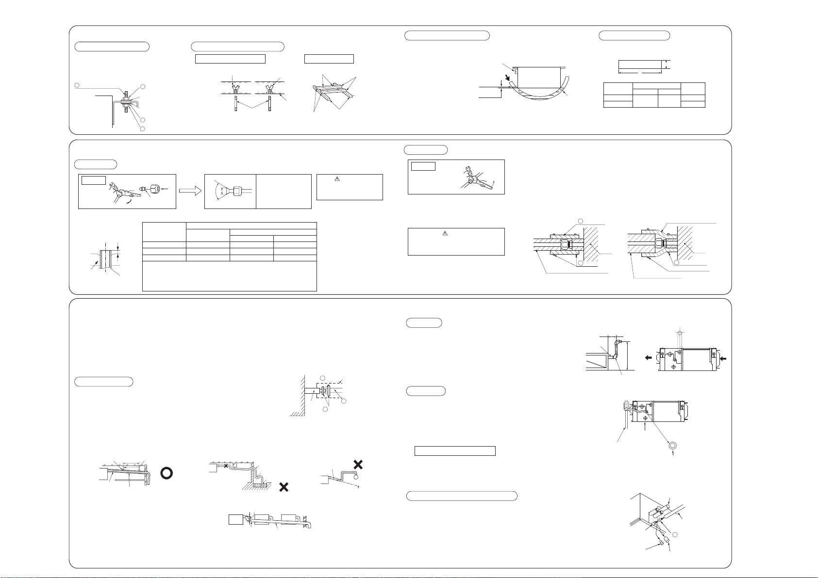
• Flaring work
Measurement B
Flaring
block
Copper pipe
○ Install the removed flared nuts to the pipes to be connected,
then flared the pipes.
○ Remove the flared nuts. (on both liquid and gas sides)
Keep the openings of the pipes covered with tapes etc. to prevent dust, sand, etc. from entering them.
CONNECTION OF REFRIGERANT PIPINGS
INSTALLATION OF INDOOR UNIT
Preparation
(Do not turn)
Press
Remove
A
90 ± 0.5˚
Dimension A
Liquid side ø6.35 : 9.1 (mm)
Gas side ø9.52 : 13.2 (mm)
ø12.7 : 16.6 (mm)
CAUTION
Do not apply refrigerating machine
oil to the flared surface.
Indoor
CAUTION
Do not apply excess torque to the flared nuts.
Otherwise, the flared nuts may crack.
○ Connect the pipes on both liquid and gas sides.
○ Tighten the nuts to the following torque.
Liquid side (ø6.35) : 14.0 - 18.0 N·m (1.4 - 1.8 kgf·m)
Gas side (ø9.52) : 34.0 - 42.0 N·m (3.4 - 4.2 kgf·m)
(ø12.7) : 49.0 - 61.0 N·m (4.9 - 6.1 kgf·m)
Connection
Indoor
(Do not turn)
RJJ012A002
Liquid side
Gas side
○ Attach the washers and nuts to the
suspension bolts.
○ Attach the hanging tool to the above
nuts, and tighten the nuts.
M10 washer
M10 nut
M10 suspension bolt
M10 nut
M10 washer
M10 spring lock washer
Main frame
Inserts
Holed anchor
Holed plug
Suspension bolts M10
Concrete
If steel embedded ceiling
Let the pipe side be slightly sloped.
Pipe side
Pour water
Water
surface
0~5mm
Vinyl hose
B
A
unit : mm
Model
25, 35
50, 60
Inlet
160
Outlet
99
Adjustment for horizontality
• Adjust so the bottom side of
the unit will be leveled with
the water surface as
illustrated below.
Air inlet and outlet size
○ Size of air inlet and outlet of the plate.
○ Cover the flare connection part of the indoor unit with attached insulation material after a gas leakage
inspection, and tighten both ends with attached bands.
• Make sure to insulate both gas pipes and liquid pipes completely.
※Incomplete insulation may cause dew condensation or water dropping.
• Use heat-resistant (120 °C or more) insulations on the gas side pipes.
• In case of using at high humidity condition, reinforce insulation of refrigerant pipes.
Surface of insulation may cause dew condition or water dropping, if insulations are not reinfoced.
<
The case of using thickness of insulation is 10mm
> <
The case of using reinfoced insulation
>
Pipe cover
Unit
Unit
Band
Band (Prepare on site)
Insulation (Prepare on site)
Pipe cover (Prepare on site)
Band
The thickness of insulation is 10mm
• If the bottom drain piping can be done with a descending gradient (1/50-1/100), it is
possible to connect the pipes as shown in the drawing below.
• When sharing a drain pipe for more than one unit, lay the main pipe 100mm
below the drain outlet of the unit. In addition, select VP-30 or bigger size for
main drain pipe.
Descending slope greater
than 1/100
VP-30 or bigger
As wide as possible
(about100mm)
○ Install the drain pipe according to the installation manual in order to drain properly.
Imperfection in draining may cause flood indoors and wetting the household goods, etc.
○ Do not put the drain pipe directly into the ditch where toxic gas such as sulfur, the other harmful and inflammable gas is generated. Toxic gas would flow into the room and it
would cause serious damage to user’s health and safety (some poisoning or deficiency of oxygen). In addition, it may cause corrosion of heat exchanger and bad smell.
○ Connect the pipe securely to avoid water leakage from the joint.
○ Insulate the pipe properly to avoid condensation drop.
○ Check if the water can flow out properly from both the drain outlet on the indoor unit and the end of the drain pipe after installation.
Insulating material
(to be removed)
Joint
Rubber stopper
(to be removed)
Standard hard polyvinyl
chloride pipe
Connecting port of bottom
drain pipes
(Outside diameter:25mm)
Connecting port of top drain pipe
DRAIN PIPE
(3) Make sure to make descending slope of greater than 1/100 and do not make up-down bend and/or trap in the midway.
• Pay attention not to give stress on the pipe on the indoor unit side, and support and fix the pipe as close place to the unit as possible when connecting the drain pipe.
• Do not set up air vent.
Drain hose
Joint
Drain hose
(VP25)
Cramp
(1) Insert the joint to the drain hose on the indoor unit and fix it securely with the clamp (small).
• Do not apply adhesives on this end.
(2) Connect the drain pipe (VP25) to the joint and fix it seaurely with the clamp (big).
• The position for drain pipe outlet can be raised up to 600mm above the ceiling. Use elbows
for installation to avoid obstacles inside ceiling. If the horizontal drain pipe is too long
before vertical pipe, the backflow of water will increase when the unit is stopped, and it
may cause overflow of water from the drain pan on the indoor unit. In order to avoid
overflow, keep the horizontal pipe length and offset of the pipe within the limit shown in the
figure below.
(4) Insulate the drain pipe.
• Be sure to insulate the joint and the drain pipe installed indoor otherwise it may cause dew condensation and water leakage.
Drain up
235~265mm
Drain hose
Maximum local
drain up dimension
Joint for VP25 (Prepare on site)
600
Right overhead
Pour water in the drain pan with a siphon.
Pouring water hose
Drain pan
Remove grommet from the unit.
Gromment
Outline of bottom drain piping work
Securing the suspension bolts
Installing the main unit
If wooden ceiling
Holes for suspention bolts
Clamps
Beams
Square bars for
suspension the
air-conditioner
○ Either use a level vial, or adjust the level according to the method below.
○ If the unit is not leveled, it may cause malfunctions or inoperation of the float switch.
Work procedure
○ Secure the suspension bolts firmly following the
illustrations and other instructions.
⑨
⑨
F
G
H
G
A
B
660
860
13
12
13
8
7
Pipe cover (Prepare on site)
Supporting fixture
Supporting metal
Air vent
No bump
No trap
Not touching
the water
Trapped air will
generate noises.
Insulation material
1.5m~2m
Descending slope greater than 1/100
○ Conduct a drainage test after completion of the electrical work and piping work.
○ During the trial, make sure that drain flows properly through the piping and that no water
leaks from connections.
○ In case of a new building, conduct the test before it is furnished with the ceiling.
○ Be sure to conduct this test even when the unit is installed in the heating season.
(1) Supply about 1000 cc of water to the unit through the air outlet by using a feed water pump.
(2) Check the drain while cooling operation.
Drain test
Procedures of drain test
7
E
Copper pipe diameter
Use a flare tool designed for R410A or a conventional flare tool.
Note that measurement B (protrusion from the flaring block) will vary depending on the type of
a flare tool in use.
If a conventional flare tool is used, use a copper pipe gauge or a similar instrument to check
protrusion so that you can keep measurement B to a correct value.
Clutch type flare tool for
R410A
Conventional (R22) flare tool
ø6.35
ø12.7
0.0 - 0.5
0.0 - 0.5
1.0 - 1.5
1.0 - 1.5
1.5 - 2.0
2.0 - 2.5
ø9.52 0.0 - 0.5 1.0 - 1.5 1.5 - 2.0
Measurement B (mm)
Clutch type Wing nut type
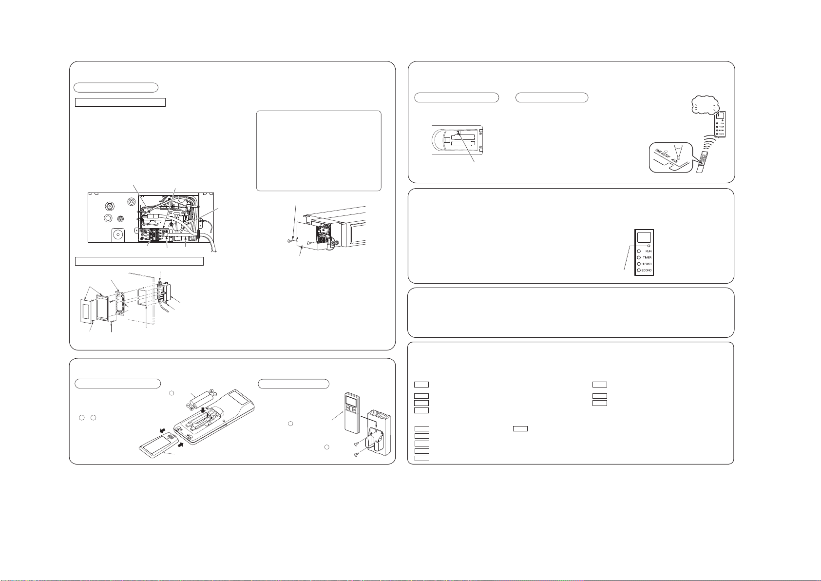
-
23
-
'15 • SR-T-185
TERMINAL CONNECTION FOR AN INTERFACE
Remove the control lid. (Remove the screw.)
There is a terminal (respectively marked with CNS) for the indoor control board.
In connecting an interface, connect to the respective terminal securely with the connection harness supplied with an optional “Interface connection kit SC-BIKN-E ” and
fasten the connection harness onto the indoor control box with the clamp supplied with the kit.
For more details, please refer to the user’s manual of your “Interface connection kit SC-BIKN-E ”.
Remove the control lid.
Remove the wiring clamp.
Connect the connecting wire to the terminal block.
1) Connect the connection wire securely. If the wire is not affixed completely,
contact will be poor, and it is dangerous as the terminal block may heat up
and catch fire.
2) Take care not to confuse the terminal numbers for indoor and outdoor
connections.
Fix the connecting wire by wiring clamp.
Connect the connector of the remote control singnal receiver to the relay wiring.
Attach the control lid.
ELECTRICAL WIRING WORK
Preparation of indoor unit
Mounting of connecting wires
Use cables for interconnection wiring to avoid loosening of the wires.
CENELEC code for cables Required field cables.
H05RNR4G1.5 (example) or 245IEC57
H Harmonized cable type
05 300/500 volts
R Natural-and/or synth, rubber wire insulation
N Polychloroprene rubber conductors insulation
R Stranded core
4or5 Number of conductors
G One conductor of the cable is the earth conductor
(yellow/green)
1.5 Section of copper wire (mm2)
○ In case of faulty wiring connection, indoor unit does not operate. Then, run lamp turns on and timer lamp blinks.
• If the bottom drain piping can be done with a descending gradient (1/50-1/100), it is
possible to connect the pipes as shown in the drawing below.
• When sharing a drain pipe for more than one unit, lay the main pipe 100mm
below the drain outlet of the unit. In addition, select VP-30 or bigger size for
main drain pipe.
Descending slope greater
than 1/100
VP-30 or bigger
As wide as possible
(about100mm)
Insulating material
(to be removed)
Joint
Rubber stopper
(to be removed)
Standard hard polyvinyl
chloride pipe
Connecting port of bottom
drain pipes
(Outside diameter:25mm)
Connecting port of top drain pipe
(3) Make sure to make descending slope of greater than 1/100 and do not make up-down bend and/or trap in the midway.
• Pay attention not to give stress on the pipe on the indoor unit side, and support and fix the pipe as close place to the unit as possible when connecting the drain pipe.
• Do not set up air vent.
(2) Connect the drain pipe (VP25) to the joint and fix it seaurely with the clamp (big).
(4) Insulate the drain pipe.
• Be sure to insulate the joint and the drain pipe installed indoor otherwise it may cause dew condensation and water leakage.
Pouring water hose
Drain pan
Remove grommet from the unit.
Gromment
Outline of bottom drain piping work
Securing the remote control signal receiver
(1) Open a through-hole on the wall to install the reception face for the
remote control signal receiver
③.
(2) Insert the remote control signal receiver
③ in the installation frame ④,
and fix the calking section.
(3) Fix the installation frame
④ on the wall using the flat head machine
screws
⑩.
(4) Fix the plate (display)
⑪ on the installation frame ④ using the flat head
machine screws packed together with the plate (display)
⑪.
⑪ Plate (display)
⑩ Flat head
machine screw
Flat head
machine screw
(In the pack of
⑪)
④ Installation frame
③
Remote control signal receiver
Cut off this section if it interferes with the wall.
CalkingCalking
Cut off this section if it interferes
with the wall.
○Conventionally, operate the wireless
remote control by holding in your hand.
○Avoid installing it on a clay wall etc.
INSTALLATION OF WIRELESS REMOTE CONTROL
Mounting method of battery
Fixing to pillar or wall
1
Wood screws
ø3.5 X 16
Wireless remote control
5
Cover
Battery
6
○Pull out the cover and mount the batteries
[R03 (AAA, Micro), s2 pieces] in the body
regularly.
(Fit the poles with the indication marks,
+ & − without fail)
○Do not use new and old batteries together.
Disconnect
When two air-conditioners are installed in the same room, use this setting when the two air-conditioners are not operated with one wireless remote control. Set the
wireless remote control and indoor unit.
INSTALLING TWO AIR-CONDITIONERS IN THE SAME ROOM
Setting the wireless remote control
Pull out the cover and take out batteries.
Disconnect the switching line next to the
battery with wire cutters.
Insert batteries. Close the cover.
Setting an indoor unit
Turn off the power source, and turn it on after 1 minute.
Point the wireless remote control that was set according
to the procedure described on the left side at the unit
display section and send a signal by pressing the ACL
switch on the wireless remote control.
Since the signal is sent in about 6 seconds after the ACL switch
is pressed, point the wireless remote control at the unit display
section for some time.
Check that the reception buzzer sound "pip" is emitted from the
indoor unit.
At completion of the setting, the indoor unit emits a buzzer sound
"pip". (If no reception tone is emitted, start the setting from the
beginning again.)
• Forced cooling operation
Turn off power source. Turn on power source again after a while. Then, press the
ON/OFF button continuously for at least 5 seconds. (The operation will start.)
Connect charge hose to check joint of outdoor unit.
Liquid side : Close the liquid valve with hexagon wrench key.
Gas side : Fully open the gas valve.
Carry out cooling operation. (If indoor temperature is low, operate
forced cooling operation.)
After low pressure gauge become 0.01MPa, stop cooling operation
and close the gas valve.
<How to pump down>
○ In order to protect the environment, be sure to pump down (recovery of refrigerant).
○ Pump down is the method of recovering refrigerant from the indoor unit to the
outdoor unit when the pipes are removed from the unit.
HOW TO RELOCATE OR DISPOSE OF THE UNIT
Unit ON/OFF button
INSTALLATION TEST CHECK POINTS
After installation
Power cables and connecting wires are securely fixed to the terminal block.
(Both indoor and outdoor)
The power source voltage is correct as the rating.
The drain hose is fixed securely.
Service valve is fully open.
No gas leaks from the joints of the service valve.
The pipe joints for indoor and outdoor pipes have been insulated.
The screw of the control lid is tightened securely.
Test run
Operation of the unit has been explained to the customer. (Three-minutes restart preventive timer)
When the air-conditioner is restarted or when changing the operation, the unit will not start operating
for approximately 3 minutes. This is to protect the unit and it is not a malfunction.
The remote control is normal.
Protective functions are not working.
Water drains smoothly.
No abnormal noise.
Air-conditioning operation is normal.
Check the following points again after completion of the installation, and before turning on the power. Conduct a test run again and ensure that the unit operates properly.
Explain to the customer how to use the unit and how to take care of the unit following the installation manual.
Reception
pip
Supporting fixture
Supporting metal
Air vent
No bump
No trap
Not touching
the water
Trapped air will
generate noises.
Insulation material
1.5m~2m
Descending slope greater than 1/100
leaks from connections.
○ In case of a new building, conduct the test before it is furnished with the ceiling.
○ Be sure to conduct this test even when the unit is installed in the heating season.
(1) Supply about 1000 cc of water to the unit through the air outlet by using a feed water pump.
(2) Check the drain while cooling operation.
Procedures of drain test
7
(1)
(3)
(2)
(5)
(6)
(4)
48 s 75mm
(1)
(2)
(1)
(2)
(3)
(3)
(1)
(2)
(1)
(2)
(3)
Earth wire shall be Yellow/Green (Y/G) in color and
longer than other AC wires for safety reason.
Be sure to connect
securely.
Terminal block
Wiring Clamp
The screw of the lid is
tightened securely
Control Lid
Connecting wire
Wiring of the remote
control signal receiver
-
24
-
'15 • SR-T-185
INSTALLATION MANUAL FOR OUTDOOR UNIT
RWC012A044A
SRC20·25·35·50
Model
DXC06·09·12·18
R410A REFRIGERANT USED
1. HAULAGE AND INSTALLATION (Take particular care in carrying in or moving the unit, and always perform such an operation with two or more persons.)
CAUTION
When a unit is hoisted with slings for haulage, take into consideration the offset of its gravity center position.
If not properly balanced, the unit can be thrown off-balance and fall.
1) Delivery
2) Portage
3) Selecting the installation location
• Deliver the unit as close as possible to the installation site before removing it from
the packaging.
• When you have to unpack the unit for a compelling reason before you haul it to
the installation point, hoist the unit with nylon slings or ropes and protection pads
so that you may not damage the unit.
• The right hand side of the unit as viewed from the front (diffuser side) is heavier.
A person carrying the right hand side must take heed of this fact. A person
carrying the left hand side must hold with his right hand the handle provided on
the front panel of the unit and with his left hand the corner column section.
Be careful of the following conditions and choose an installation place.
• Where air is not trapped.
• Where the installation fittings can be firmly installed.
• Where wind does not hinder the intake and outlet pipes.
• Out of the heat range of other heat sources.
• A place where stringent regulation of electric noises is not applicable.
• Where it is safe for the drain water to be discharged.
• Where noise and hot air will not bother neighboring residents.
• Where snow will not accumulate.
• Where strong winds will not blow against the outlet pipe.
• A place where no TV set or radio receiver is placed within 1m.
(If electrical interference is caused, seek a place less likely to cause the problem)
• If a operation is conducted when the outdoor air temperature is –5 C lower, the outdoor unit should be
installed at a place where it is not influenced by natural wind.
• Where it is likely that the unit is subjected to strong winds, provide wind guards according to the
following guidelines. Strong winds can cause performance degradation, an accidental stop due to a rise of
high pressure and a broken fan.
Do not install the unit in places which exposed to sea breeze (e.g. coastal area) or calcium chloride (e.g.
snow melting agent), exposed to ammonia substance (e.g. organic fertilizer).
Notabilia as a unit designed for R410A
• Do not use any refrigerant other than R410A. R410A will rise to pressure about 1.6 times higher than that of a conventional refrigerant.
A cylinder containing R410A has a pink indication mark on the top.
• A unit designed for R410A has adopted a different size indoor unit servic valve charge port and a different size check joint provided in the unit to prevent the charging of a wrong refrigerant by mistake.
The processed dimension of the flared part of a refrigerant pipe and a flare nut’s parallel side measurement have also been altered to raise strength against pressure.
Accordingly, you are required to arrange dedicated R410A tools listed in the table on the left before installing or servicing this unit.
• Do not use a charge cylinder. The use of a charge cylinder will cause the refrigerant composition to change, which results in performance degradation.
• In charging refrigerant, always take it out from a cylinder in the liquid phase.
• All indoor units must be models designed exclusively for R410A. Check connectable indoor unit models in a catalog, etc. (A wrong indoor unit, if connected into the system, will impair proper system operation)
• Read the “SAFETY PRECAUTIONS” carefully first of all and strictly follow it during the installation work in order
to protect yourself.
• The precautionary items mentioned below are distinguished into two levels, and .
: Wrong installation would cause serious consequences such as injuries or death.
: Wrong installation might cause serious consequences depending on circumstances.
Both mentions the important items to protect your health and safety so strictly follow them by any means.
• Be sure to confirm no anomaly on the equipment by commissioning after completed installation and explain the
operating methods as well as the maintenance methods of this equipment to the user according to the owner’s
manual.
• Keep the installation manual together with owner’s manual at a place where any user can read at any time.
Moreover if necessary, ask to hand them to a new user.
• For installing qualified personnel, take precautions in respect to themselves by using suitable protective
clothing, groves, etc., and then perform the installation works.
• Please pay attention not to fall down the tools, etc. when installing the unit at the high position.
• If unusual noise can be heard during operation, consult the dealer.
• The meanings of “Marks” used here are shown as follows:
• This installation manual deals with outdoor units and general installation specifications only. For indoor units, refer to page 20.
• When install the unit, be sure to check whether the selection of installation place, power source specifications, usage limitation (piping length, height differences between indoor and outdoor units, power
source voltage and etc.) and installation spaces.
SAFETY PRECAUTIONS
WARNING
Never do it under any circumstances. Always do it according to the instruction.
CAUTIONWARNING
CAUTION
WARNING
• Installation must be carried out by the qualified installer.
If you install the system by yourself, it may cause serious trouble such as water leaks,
electric shocks, fire and personal injury, as a result of a system malfunction. Do not
carry out the installation and maintenance work except the by qualified installer.
• Install the system in full accordance with the installation manual.
Incorrect installation may cause bursts, personal injury, water leaks, electric
shocks and fire.
• Be sure to use only for household and residence.
If this appliance is installed in inferior environment such as machine shop and etc.,
it can cause malfunction.
• When installing in small rooms, take prevention measures not to
exceed the density limit of refrigerant in the event of leakage, referred
by the formula (accordance with ISO5149).
If the density of refrigerant exceeds the limit, please consult the dealer and install
the ventilation system, otherwise lack of oxygen can occur, which can cause serious
accident.
• Use the original accessories and the specified components for
installation.
If parts other than those prescribed by us are used, It may cause water leaks,
electric shocks, fire and personal injury.
• Install the unit in a location with good support.
Unsuitable installation locations can cause the unit to fall and cause material
damage and personal injury.
• Ensure the unit is stable when installed, so that it can withstand
earthquakes and strong winds.
Unsuitable installation locations can cause the unit to fall and cause material
damage and personal injury.
• Ventilate the working area well in the event of refrigerant leakage during
installation.
If the refrigerant comes into contact with naked flames, poisonous gas is produced.
• Use the prescribed pipes, flare nuts and tools for R410A.
Using existing parts (for R22 or R407C) can cause the unit failure and serious
accidents due to burst of the refrigerant circuit.
• Tighten the flare nut by torque wrench with specified method.
If the flare nut were tightened with excess torque, this may cause burst and
refrigerant leakage after a long period.
• Do not open the service valves for liquid line and gas line until
completed refrigerant piping work, air tightness test and evacuation.
If the compressor is operated in state of opening service valves before completed
connection of refrigerant piping work, air can be sucked into refrigerant circuit,
which can cause bust or personal injury due to anomalously high pressure in the
refrigerant.
• The electrical installation must be carried out by the qualified electrician
in accordance with “the norm for electrical work” and “national wiring
regulation”, and the system must be connected to the dedicated circuit.
Power source with insufficient capacity and incorrect function done by improper
work can cause electric shocks and fire.
• Be sure to shut off the power before starting electrical work.
Failure to shut off the power can cause electric shocks, unit failure or incorrect
function of equipment.
• Be sure to use the cables conformed to safety standard and cable
ampacity for power distribution work.
Unconformable cables can cause electric leak, anomalous heat production or fire.
• This appliance must be connected to main power source by means of a
circuit breaker or switch (fuse:16A) with a contact separation of at least
3mm.
• Arrange the wiring in the control box so that it cannot be pushed up
further into the box. Install the service panel correctly.
Incorrect installation may result in overheating and fire.
• Use the prescribed cables for electrical connection, tighten the cables
securely in terminal block and relieve the cables correctly to prevent
overloading the terminal blocks.
Loose connections or cable mountings can cause anomalous heat production or fire.
• Be sure to fix up the service panels.
Incorrect fixing can cause electric shocks or fire due to intrusion of dust or water.
• Be sure to switch off the power source in the event of installation,
inspection or servicing.
If the power source is not shut off, there is a risk of electric shocks, unit failure or
personal injury due to the unexpected start of fan.
• Stop the compressor before removing the pipe after shutting the
operation valve on pump down work.
If the pipe is removed when the compressor is in operation with the service valve
open, air would be mixed in the refrigeration circuit and it could cause explosion
and injuries due to abnormal high pressure in the cooling cycle.
• Only use prescribed option parts. The installation must be carried out
by the qualified installer.
If you install the system by yourself, it can cause serious trouble such as water
leaks, electric shocks, fire.
• Be sure to wear protective goggles and gloves while at work.
• Earth leakage breaker must be installed.
If the earth leakage breaker is not installed, it can cause electric shocks.
• Ensure that no air enters in the refrigerant circuit when the unit is
installed and removed.
If air enters in the refrigerant circuit, the pressure in the refrigerant circuit
becomes too h igh, which can cause burst and personal injur y.
•
Do not processing, splice the power cord, or share a socket with other power plugs.
This may cause fire or electric shock due to defecting contact, defecting insulation
and over-current etc.
• Do not bundling, winding or processing for the power cable. Or, do not
deforming the power plug due to tread it.
This may cause fire or heating.
• Do not run the unit with removed panels or protections.
Touching rotating equipments, hot surfaces or high voltage parts can cause
personal injury due to entrapment, burn or electric shocks.
• Do not perform any change of protective device itself or its setup
condition.
The forced operation by short-circuiting protective device of pressure switch and
temperature controller or the use of non specified component can cause fire or
burst.
(2) Installation of outdoor unit
-
25
-
'15 • SR-T-185
Accessories for outdoor unit
• Model name and power source
• Refrigerant piping length
• Piping, wiring and miscellaneous small parts
• Indoor unit installation manual
Necessary tools for the installation work
Wrench key (Hexagon) [4m/m]
Vacuum pump
Vacuum pump adapter (Anti-reverse flow type)
(Designed specifically for R410A)
Gauge manifold (Designed specifically for R410A)
Charge hose (Designed specifically for R410A)
Flaring tool set (Designed specifically for R410A)
Gas leak detector (Designed specifically for R410A)
Gauge for projection adjustment
(Used when flare is made by using conventional flare tool)
9
10
11
12
13
14
15
16
Plus headed driver
Knife
Saw
Tape measure
Hammer
Spanner wrench
Torque wrench [14.0~62.0N·m (1.4~6.2kgf·m)]
Hole core drill (65mm in diameter)
1
2
3
4
5
6
7
8
Grommet
(Heat pump
type only)
SRC20~35
Model
DXC06~12
Model SRC50/DXC18
Q’ty
1
4
1
Option parts
Sealing plate
Sleeve
Inclination plate
Putty
Drain hose (extension hose)
Piping cover
(for insulation of connection piping)
Q’ty
1
1
1
1
1
1
1Drain elbow (Heat pump type only)
Check before installation work
a
b
c
d
e
f
2
(1) If the unit is installed in the area where the snow will accumulate, following measures are required.
The bottom plate of unit and intake, outlet may be blocked by snow.
1 Install the unit on the base so that the bottom is
higher than snow cover surface.
Since drain water generated by defrost control may freeze, following measures are required.
• Do not execute drain piping work by using a drain elbow and drain grommets (accessories).
[Refer to Drain piping work.]
Determine refrigerant pipe size pursuant to the following guidelines based on
the indoor unit specifications.
• Where wind does not hinder the intake and outlet pipes.
• Out of the heat range of other heat sources.
• A place where stringent regulation of electric noises is not applicable.
• Where it is safe for the drain water to be discharged.
• Where noise and hot air will not bother neighboring residents.
• Where snow will not accumulate.
• Where strong winds will not blow against the outlet pipe.
• A place where no TV set or radio receiver is placed within 1m.
(If electrical interference is caused, seek a place less likely to cause the problem)
• If a operation is conducted when the outdoor air temperature is –5 C lower, the outdoor unit should be
installed at a place where it is not influenced by natural wind.
• Where it is likely that the unit is subjected to strong winds, provide wind guards according to the
following guidelines. Strong winds can cause performance degradation, an accidental stop due to a rise of
high pressure and a broken fan.
Do not install the unit in places which exposed to sea breeze (e.g. coastal area) or calcium chloride (e.g.
snow melting agent), exposed to ammonia substance (e.g. organic fertilizer).
2. REFRIGERANT PIPING WORK
1) Restrictions on unit installation and use
2) Determination of pipe size
The use restrictions appearing in the table above are applicable to the standard pipe size combinations shown in the table below.
Restrictions
Main pipe length
When the outdoor unit is positioned higher,
When the outdoor unit is positioned lower,
Elevation difference between
indoor and outdoor units
4) Caution about selection of installation location
• Check the following points in light of the indoor unit specifications and the installation site.
• Observe the following restrictions on unit installation and use. Improper installation can result in a compressor failure or performance degradation.
• Additional refrigerant charge is not required at all (Model SRC20
ø9.52
Flare
ø9.52
ø9.52
Gas pipe
ø6.35
Flare
ø6.35
ø6.35
Model SRC20~35/DXC06
Liquid pipe
Outdoor unit connected
Refrigerant piping (branch pipe L)
Indoor unit connected
CAUTION
CAUTION
• Carry out the electrical work for ground lead with care.
Do not connect the ground lead to the gas line, water line, lightning conductor or telephone line’s ground lead. Incorrect grounding can cause unit faults such as electric shocks due to short-circuiting.
installation.
If parts other than those prescribed by us are used, It may cause water leaks,
electric shocks, fire and personal injury.
• Install the unit in a location with good support.
Unsuitable installation locations can cause the unit to fall and cause material
damage and personal injury.
• Ensure the unit is stable when installed, so that it can withstand
earthquakes and strong winds.
Unsuitable installation locations can cause the unit to fall and cause material
damage and personal injury.
regulation”, and the system must be connected to the dedicated circuit.
Power source with insufficient capacity and incorrect function done by improper
work can cause electric shocks and fire.
• Be sure to shut off the power before starting electrical work.
Failure to shut off the power can cause electric shocks, unit failure or incorrect
function of equipment.
• Be sure to use the cables conformed to safety standard and cable
ampacity for power distribution work.
Unconformable cables can cause electric leak, anomalous heat production or fire.
• This appliance must be connected to main power source by means of a
If the pipe is removed when the compressor is in operation with the service valve
open, air would be mixed in the refrigeration circuit and it could cause explosion
and injuries due to abnormal high pressure in the cooling cycle.
• Only use prescribed option parts. The installation must be carried out
by the qualified installer.
If you install the system by yourself, it can cause serious trouble such as water
leaks, electric shocks, fire.
• Be sure to wear protective goggles and gloves while at work.
• Earth leakage breaker must be installed.
If the earth leakage breaker is not installed, it can cause electric shocks.
• Ensure that no air enters in the refrigerant circuit when the unit is
installed and removed.
If air enters in the refrigerant circuit, the pressure in the refrigerant circuit
becomes too h igh, which can cause burst and personal injur y.
•
Do not processing, splice the power cord, or share a socket with other power plugs.
This may cause fire or electric shock due to defecting contact, defecting insulation
and over-current etc.
• Do not bundling, winding or processing for the power cable. Or, do not
deforming the power plug due to tread it.
This may cause fire or heating.
• Do not run the unit with removed panels or protections.
Touching rotating equipments, hot surfaces or high voltage parts can cause
personal injury due to entrapment, burn or electric shocks.
• Do not perform any change of protective device itself or its setup
condition.
The forced operation by short-circuiting protective device of pressure switch and
temperature controller or the use of non specified component can cause fire or
burst.
• Use the circuit breaker for all pole correct capacity. Circuit breaker
should be the one that disconnect all poles under over current.
Using the incorrect circuit breaker, it can cause the unit malfunction and fire.
• Install isolator or disconnect switch on the power source wiring in
accordance with the local codes and regulations.
The isolator should be locked in OFF state in accordance with EN60204-1.
• After maintenance, all wiring, wiring ties and the like, should be returned
to their original state and wiring route, and the necessary clearance from
all metal parts should be secured.
• Secure a space for installation, inspection and maintenance specified in
the manual.
Insufficient space can result in accident such as personal injury due to falling from
the installation place.
• Take care when carrying the unit by hand.
If the unit weights more than 20kg, it must be carried by two or more persons. Do
not carry by the plastic straps, always use the carry handle when carrying the unit
by hand. Use gloves to minimize the risk of cuts by the aluminum fins.
• Dispose of any packing materials correctly.
Any remaining packing materials can cause personal injury as it contains nails and
wood. And to avoid danger of suffocation, be sur e to keep the plastic wrapper
away from children and to dispose after tear it up.
• Be sure to insulate the refrigerant pipes so as not to condense the
ambient air moisture on them.
Insufficient insula tion can cause conde nsation, which can l ead to moisture
damage on the ceiling, floor, furniture and any other valuables.
• When perform the air conditioner operation (cooling or drying operation)
in which ventilator is installed in the room. In this case, using the air
conditioner in parallel with the ventilator, there is the possibility that
drain water may backflow in accordance with the room lapse into the
negative pressure status. Therefore, set up the opening port such as
incorporate the air into the room that may appropriate to ventilation (For
example; Open the door a little). In addition, just as above, so set up the
opening port if the room lapse into negative pressure status due to
register of the wind for the high rise apartment etc.
• Do not install the unit in the locations listed below.
•Locations where carbon fiber, metal powde r or any powder is floating.
•Locations where any substances that can affect the unit such as sulphide gas,
chloride gas, acid and alkaline can occur.
•Vehicles and ships.
•Locations where cosmetic or special sprays are often used.
•Locations with direct exposure of oil mist and steam suc h as kitchen and
machine plant.
•Locations where any machines which generate high frequency h a r m o n i c s are
used.
•Locations with salty atmospheres such as coastlines.
•Locations with heavy snow (If installed, be sure to prov i d e base flame and snow
hood mentioned in the manual).
•Locations where the unit is exposed to chimney smoke.
•Locations at high altitude (more than 1000m high).
•Locations with ammonic atmospheres (e.g. organic fertilizer).
•Locations with calcium chloride (e.g. snow melting agent).
•Locations where heat radiation from other heat source can affect the unit.
•Locations without good air circulation.
•Locations with any obstacles which can prevent inlet and outlet air of the unit.
•Locations where short circuit of air can occur (in case of multiple units
installation).
•Locations where strong air blows against the air outlet of outdoor unit.
•Locations where something located above the unit could fall.
It can cause remarkable decrease in performance, corrosion and damage of
components, malfunction and fire.
• Do not install the outdoor unit in the locations listed below.
• Locations where discharged hot air or operating sound of the outdoor unit ca n
bother neighborhood.
• Locations where outlet air of the outdoor unit blows directly to an animal or
plants. The outlet air can affect adversely to the plant etc.
• Locations where vibration can be amplified and transmitted due to insufficient
strength of structure.
• Locations where vibration and operation sound generated by the outdoor unit
can affect seriously (on the wall or at the place near bed room).
• Locations where an equipment affected by high harmonics is placed (TV set or
radio receiver is placed within 1m).
• Locations where drainage cannot run off safely.
It can affect surrounding environment and cause a claim.
• Do not install the unit near the location where leakage of combustible
gases can occur.
If leaked gases accumulate around the unit, it can cause fire.
• Do not install the unit where corrosive gas (such as sulfurous acid gas etc.)
or combustible gas (such as thinner and petroleum gases) can accumulate
or collect, or wherevolatile combustible substances are handled.
Corrosive gas can cause corrosion of heat exchang er, breakage of plastic parts
and etc. And combustible gas can cause fire.
• Do not install nor use the system close to the equipment that generates
electromagnetic fields or high frequency harmonics.
Equipment such as inverters, standby generators, medical high fre q u e n c y
equipments and telecommunication equipments can affect the system, and cause
malfunctions and breakdowns. The system can also affect medical equipment and
telecommunication equipment, and obstruct its function or cause j a m m i n g.
•Do not install the outdoor unit in a location where insects and small
animals can inhabit.
Insects and small animals can enter the electric parts and cause damage or fire.
Instruct the user to keep the surroundings clean.
•Do not use the base flame for outdoor unit which is corroded or damaged
due to long periods of operation.
Using an old and damage base flame can cause the unit falling down and cause
personal injury.
•Do not use any materials other than a fuse with the correct rating in the
location where fuses are to be used.
Connecting the circuit with copper wire or other metal thread can cause unit
failure and f ire.
•Do not touch any buttons with wet hands.
It can cause electric shocks.
•Do not touch any refrigerant pipes with your hands when the system is in
operation.
During operation the refrigerant pipes become extremely hot or extremely cold
depending the operating condition, and it can cause burn inju ry or frost injury.
•Do not touch the suction or aluminum fin on the outdoor unit.
This may cause injury.
•Do not put anything on the outdoor unit and operating unit.
This may cause damage the objects or injury due to falling to the object.
•Do not use the unit for special purposes such as storing foods, cooling
precision instruments and preservation of animals, plants or art.
•Do not clean up the unit with water.
Notabilia as a unit designed for R410A
• Do not use any refrigerant other than R410A. R410A will rise to pressure about 1.6 times higher than that of a conventional refrigerant.
A cylinder containing R410A has a pink indication mark on the top.
• A unit designed for R410A has adopted a different size indoor unit servic valve charge port and a different size check joint provided in the unit to prevent the charging of a wrong refrigerant by mistake.
The processed dimension of the flared part of a refrigerant pipe and a flare nut’s parallel side measurement have also been altered to raise strength against pressure.
Accordingly, you are required to arrange dedicated R410A tools listed in the table on the left before installing or servicing this unit.
• Do not use a charge cylinder. The use of a charge cylinder will cause the refrigerant composition to change, which results in performance degradation.
• In charging refrigerant, always take it out from a cylinder in the liquid phase.
• All indoor units must be models designed exclusively for R410A. Check connectable indoor unit models in a catalog, etc. (A wrong indoor unit, if connected into the system, will impair proper system operation)
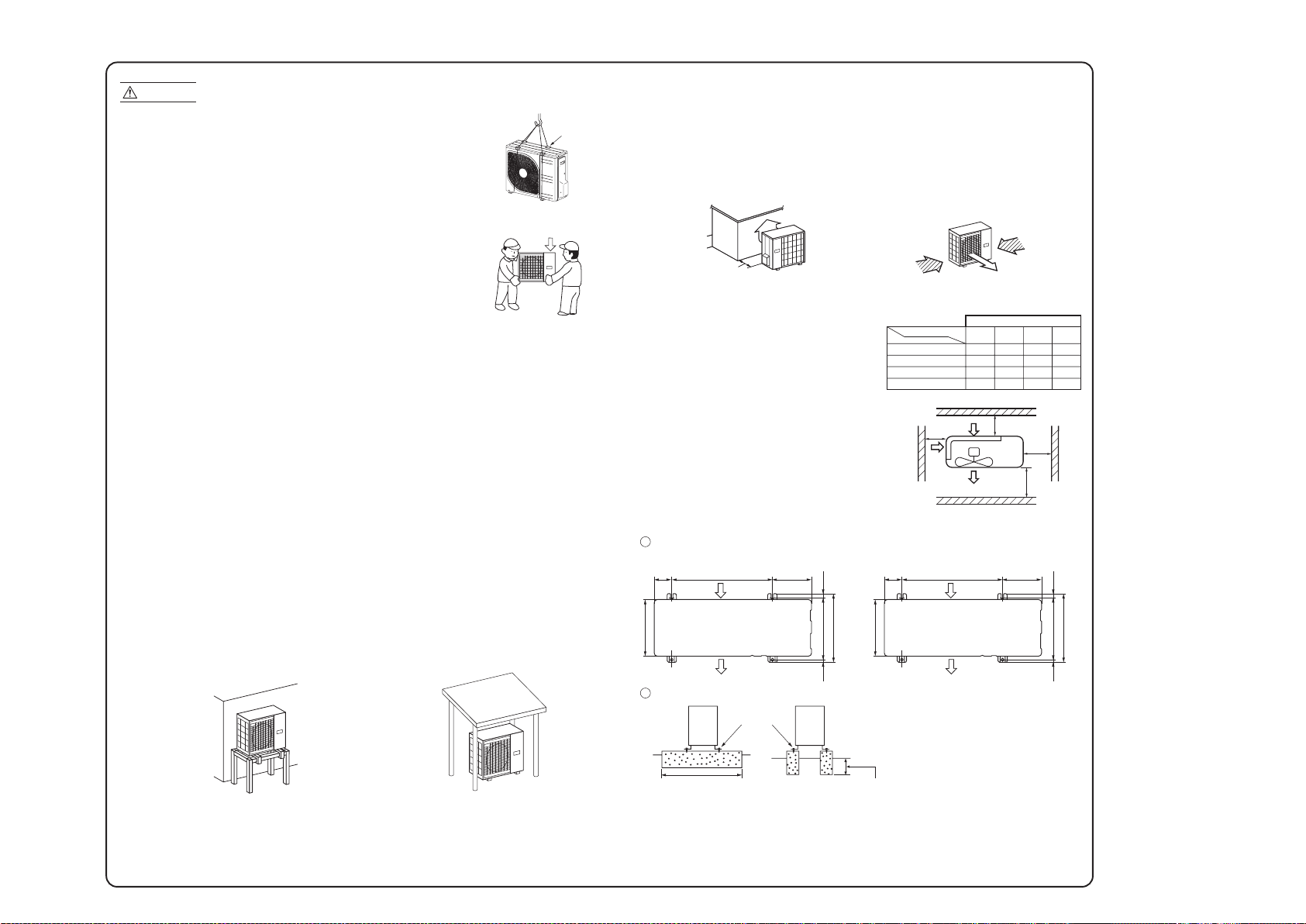
-
26
-
'15 • SR-T-185
1. HAULAGE AND INSTALLATION (Take particular care in carrying in or moving the unit, and always perform such an operation with two or more persons.)
Intake
The height of a wall is 1200mm or less.
(
service
space
)
Intake
Outlet
Fasten with bolts
(M10-12)
Use a thicker block to anchor deeper.Use a long block to extend the width.
CAUTION
When a unit is hoisted with slings for haulage, take into consideration the offset of its gravity center position.
If not properly balanced, the unit can be thrown off-balance and fall.
1) Delivery
2) Portage
3) Selecting the installation location
5) Installation space
L3
L2
L4
L1
Model SRC20~50/DXC06~18
Model SRC20~35/DXC06~12
Example installation
Size
L1
L2
L3
L4
Open
100
100
250
280
75
80
Open
280
Open
80
250
180
Open
80
Open
(mm)
I II III IV
6) Installation
Pad
Over 500mm
Intake
Outlet
312.5
24.314.8
290
111.6
510 158.4
351.6
Model SRC50/DXC18
Intake
Outlet
312.5
24.314.8
290
89
510 201
351.6
• Deliver the unit as close as possible to the installation site before removing it from
the packaging.
• When you have to unpack the unit for a compelling reason before you haul it to
the installation point, hoist the unit with nylon slings or ropes and protection pads
so that you may not damage the unit.
• The right hand side of the unit as viewed from the front (diffuser side) is heavier.
A person carrying the right hand side must take heed of this fact. A person
carrying the left hand side must hold with his right hand the handle provided on
the front panel of the unit and with his left hand the corner column section.
(1) If the unit is installed in the area where the snow will accumulate, following measures are required.
The bottom plate of unit and intake, outlet may be blocked by snow.
1 Install the unit on the base so that the bottom is
higher than snow cover surface.
Since drain water generated by defrost control may freeze, following measures are required.
• Do not execute drain piping work by using a drain elbow and drain grommets (accessories).
[Refer to Drain piping work.]
2 Install the unit under or provide the roof on site.
Be careful of the following conditions and choose an installation place.
• Where air is not trapped.
• Where the installation fittings can be firmly installed.
• Where wind does not hinder the intake and outlet pipes.
• Out of the heat range of other heat sources.
• A place where stringent regulation of electric noises is not applicable.
• Where it is safe for the drain water to be discharged.
• Where noise and hot air will not bother neighboring residents.
• Where snow will not accumulate.
• Where strong winds will not blow against the outlet pipe.
• A place where no TV set or radio receiver is placed within 1m.
(If electrical interference is caused, seek a place less likely to cause the problem)
• If a operation is conducted when the outdoor air temperature is –5 C lower, the outdoor unit should be
installed at a place where it is not influenced by natural wind.
• Where it is likely that the unit is subjected to strong winds, provide wind guards according to the
following guidelines. Strong winds can cause performance degradation, an accidental stop due to a rise of
high pressure and a broken fan.
Do not install the unit in places which exposed to sea breeze (e.g. coastal area) or calcium chloride (e.g.
snow melting agent), exposed to ammonia substance (e.g. organic fertilizer).
4) Caution about selection of installation location
• Walls surrounding the unit in the four sides are not
acceptable.
• There must be a 1-meter or larger space in the above.
• When more than one unit are installed side by side,
provide a 250mm or wider interval between them as a
service space. In order to facilitate servicing of
controllers, please provide a sufficient space between
units so that their top plates can be removed easily.
• Where a danger of short-circuiting exists, install guide
louvers.
• When more than one unit are installed, provide sufficient
intake space consciously so that short-circuiting may not
occur.
• Where piling snow can bury the outdoor unit, provide
proper snow guards.
• In installing the unit, fix the unit’s legs with bolts specified on the above.
• The protrusion of an anchor bolt on the front side must be kept within 15mm.
• Securely install the unit so that it does not fall over during earthquakes or strong winds, etc.
• Refer to the above illustrations for information regarding concrete foundations.
• Install the unit in a level area. (With a gradient of 5mm or less.) Improper installation can result in a
compressor failure, broken piping within the unit and abnormal noise generation.
1 Anchor bolt fixed position
2 Notabilia for installation
(2) If the unit can be affected by strong wind, following measures are required.
Strong wind can cause damage of fan (fan motor), or can cause performance degradation, or can trigger
anomalous stop of the unit due to rising of high pressure.
1 Place the unit outlet side is turned to the wall. 2 Install so the direction of the air from the
blowing outlet will be perpendicular to the
direction of the wind.
• Do not use a charge cylinder. The use of a charge cylinder will cause the refrigerant composition to change, which results in performance degradation.
• In charging refrigerant, always take it out from a cylinder in the liquid phase.
• All indoor units must be models designed exclusively for R410A. Check connectable indoor unit models in a catalog, etc. (A wrong indoor unit, if connected into the system, will impair proper system operation)
Over 500mm
Heavy
Wind
direction
Wind
direction
 Loading...