

Mitsubishi Heavy Industries SRK52CF-BN, SRK71CF-BN, SRK52CF-BP, SRK71CF-BP Technical Manual

-
3
-
WALL MOUNTED TYPE
ROOM AIR-CONDITIONER
TECHNICAL MANUAL
Collection data
Manual No. ’06
.
SRK-T
.
062
(Split system, air cooled cooling only type)
SRK52CF-BN, 71CF-BN
SRK52CF-BP, 71CF-BP

-
1
-
CONTENTS
1. GENERAL INFORMATION .............................................................................. 1
1.1 Specific features ....................................................................................... 1
1.2 How to read the model name ................................................................... 1
2. SELECTION DATA .......................................................................................... 2
2.1 Specifications ........................................................................................... 2
2.2 Range of usage & limitations .................................................................. 6
2.3 Exterior dimensions ................................................................................. 6
2.4 Piping system ........................................................................................... 8
2.5 Selection chart .......................................................................................... 9
3. ELECTRICAL DATA ........................................................................................ 10
3.1 Electrical wiring ........................................................................................ 10
4. OUTLINE OF OPERATION CONTROL BY MICROCOMPUTER ................... 14
4.1 Operation control function by remote control switch ........................... 14
4.2 Unit ON/OFF button .................................................................................. 16
4.3 Power blackout auto restart function ..................................................... 16
4.4 Custom cord switching procedure ......................................................... 17
4.5 Flap and louver control ............................................................................ 17
4.6 Comfortable timer setting ........................................................................ 18
4.7 Sleep timer operation ............................................................................... 18
4.8 Outline of cooling operation .................................................................... 19
4.9 Outline of dehumidifying operation ........................................................ 20
4.10 Outline of automatic operation................................................................ 21
4.11 Set temperature selection ........................................................................ 21
4.12 Outline of fan operation ........................................................................... 22
4.13 Regulation of outdoor air flow................................................................. 22
4.14 Stop mode ................................................................................................. 23
4.15 External control (remote display)/control of input signal ..................... 24
4.16 Operation permission/prohibition control.............................................. 25
4.17 Protective control function ...................................................................... 25
4.18 List of indoor unit jumper selections...................................................... 28
5. APPLICATION DATA ....................................................................................... 29
5.1 Selection of location for installation ....................................................... 30
5.2 Installation of indoor unit ......................................................................... 31
5.3 Installation of outdoor unit ...................................................................... 34
5.4 Refrigerant piping ..................................................................................... 34
5.5 Test run ...................................................................................................... 36
5.6 Precautions for wireless remote control installation and operation ........ 36
5.7 Installation of wired remote control and super link
adapter (SC-AD-ER) (Optional parts) ...................................................... 37
6. MAINTENANCE DATA .................................................................................... 44
6.1 Troubleshooting procedures for electrical equipment ......................... 44
6.2 Servicing.................................................................................................... 52
-
1
-
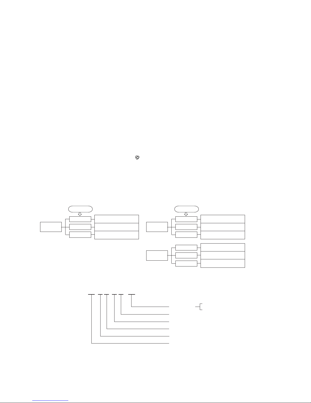
Power supply
Series No.
Cooling only type
Product capacity
Wall mounted type
Split type room air-conditioner
1.2 How to read the model name
Example : SR K 52 C F - BN
TIMER lightRUN light
Error of signal transmission
1 GENERAL INFORMATION
1.1 Specific features
The “MITSUBISHI HEAVY INDUSTRIES, LTD.” room air-conditioner: SRK series are of split and wall mounted type and the unit
consists of indoor unit and outdoor unit with refrigerant precharged in factory. The indoor unit is composed of room air cooling equip-
ment with operation control switch and the outdoor unit is composed of condensing unit with compressor.
(1) Remote control flap & louver
The flap & louver can be automatically controlled by operating wireless remote control.
¡Flap swing : The flaps swing up and down successively.
¡Louver swing : The louvers swing left and right successively.
¡Multi-directional Air Flow : Activating both up/down air swing and left/right air swing at the same time results in a multi-
directional air flow.
¡Memory flap : Once the flap & louver position is set, the unit memorizes the position and continues to operate
at the same position from the next time.
(2) Automatic operation
When the remote control switch is set on “auto(
) ”, it will either automatically decide operation mode such as cooling and
thermal dry, or operate in the operation mode before it has been turned to automatic control.
(3) Self diagnosis function
¡ We are constantly trying to do better service to our customers by installing such judges that show abnormality of operation as
follows.
Room temperature sensor error
Indoor fan motor error
Heat exchanger sensor error
2 time flash
6 time flash
TIMER light
ON
Outdoor heat exchanger sensor
error
Discharge pipe temp. sensor error
Outdoor temperature sensor error
2 time flash
4 time flash
RUN light
keeps flashing
1 time flash
Trouble of outdoor unit
Over heat of compressor
2 time flash
5 time flash
RUN light
ON
6 time flash
(up/down air scroll and
left/right air scroll)
1 time flash
BN: 1 Phase 220-240V 50Hz
BP: 1 Phase 220V 60Hz
-
2
-
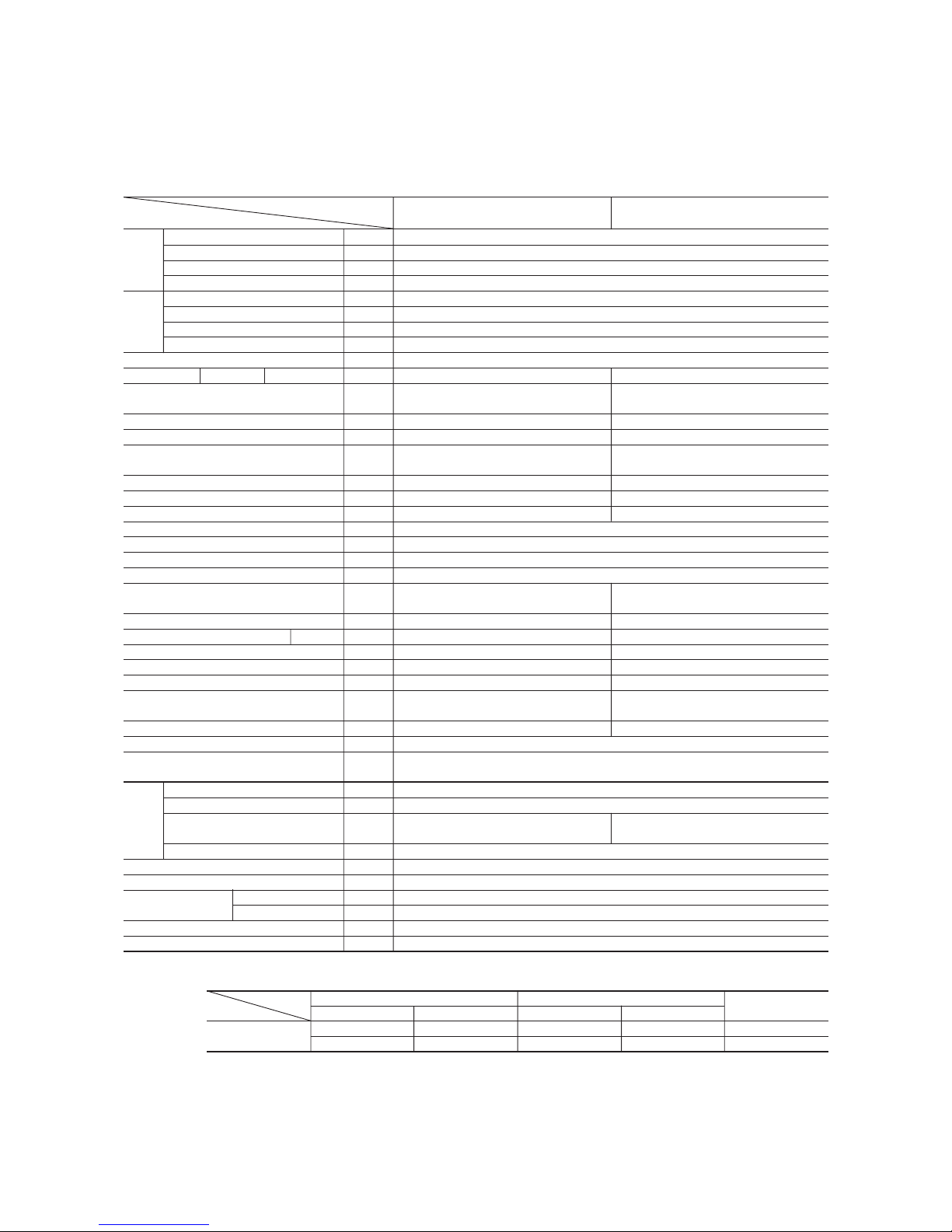
Item
Model
SRK52CF-BN SRC52CF-BN
Cooling capacity kW 5.4 / 5.4
Cooling power input kW 1.76 / 1.91
Energy efficiency ratio Btu/hW 10.47 / 9.66
Rating current A 8.8 / 8.7
Cooling capacity kW 5.0 / 5.0
Cooling power input kW 2.06 / 2.20
Energy efficiency ratio Btu/hW 8.29 / 7.75
Rating current A 10.3 / 10.1
Power source 1 Phase, 220-240V, 50Hz
Noise level Cooling Sound level dB Hi 43, Me 40, Lo 37 49
Exterior dimensions
Height × Width × Depth
mm
318 × 1098 × 248 640 × 850 × 290
Color Yellowish white Stucco white
Net weight kg 15 46
Refrigerant equipment
Compressor type & Q’ty
– 2KS314D5AB04 (Rotary type) × 1
Motor kW – 1.5
Starting method – Line starting
Heat exchanger Slit fins & inner grooved tubing Straight fin & inner grooved tubing
Refrigerant control Capillary tubes + Electric expansion valve
Refrigerant
(3)
kg R22 1.25 (Pre-Charged up to the piping length of 7m)
Refrigerant oil R 0.67 (ATMOS NM56M or SUNISO 4DGID)
Deice control Microcomputer control
Air handling equipment
Fan type & Q’ty
Tangential fan × 1 Propeller fan × 1
Motor W 46 35
Air flow (at High) (Cooling)
CMM
20 38
Air filter, Q’ty Polypropylene net (washable) × 2–
Shock & vibration absorber – Cushion rubber (for compressor)
Electric heater ––
Operation control
Operation switch
Wireless-Remote control –
Room temperature control Microcomputer thermostat –
Pilot lamp RUN (Green), TIMER (Yellow), HI POWER (Green), ECONO (Orange)
Safety equipment
O.D mm (in) Liquid line: φ6.35 (1/4″) Gas line: φ15.88 (5/8″)
Connecting method Flare connecting
Attached length of piping Liquid line: 0.70m
Gas line: 0.63m
–
Insulation Necessary (Both sides)
Drain hose Connectable
Power source supply Terminal block (Screw fixing type)
Size × Core number 1.5 mm2 × 4 cores (Including earth cable)
Connection wiring
Connecting method Terminal block (Screw fixing type)
Accessories (included)
Mounting kit, Clean filter (Natural enzyme filter × 1, Photocatalytic washable deodorizing filter × 1)
Optional parts Wired-Remote control
Notes (1) The data are measured at the following conditions.
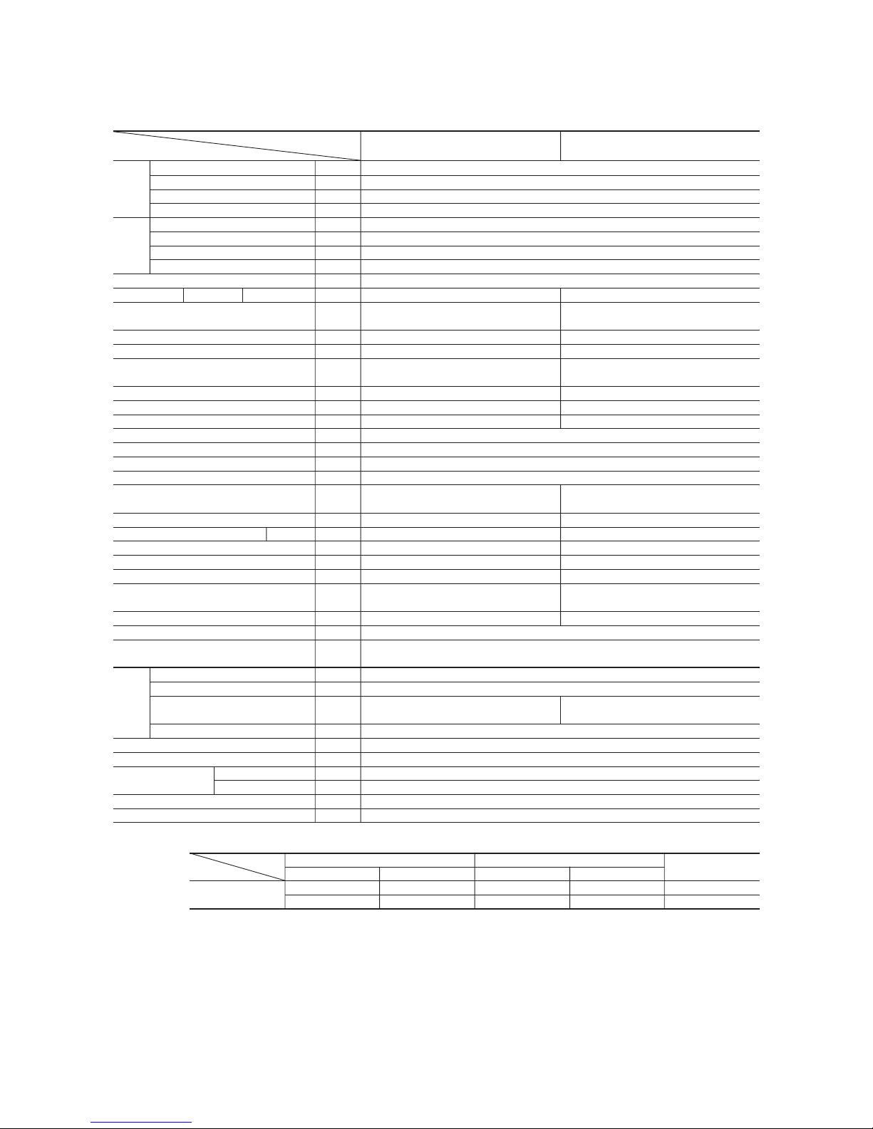
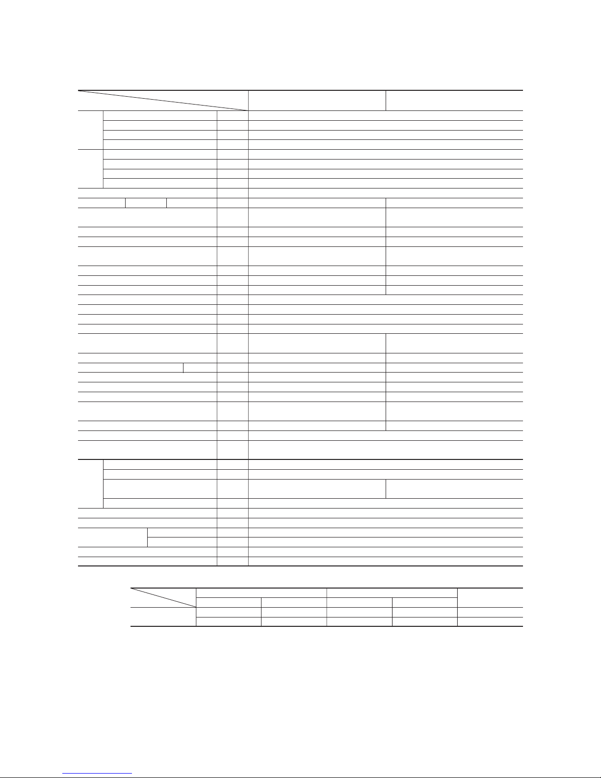
2. SELECTION DATA
2.1 Specifications
Model SRK52CF-BN (Indoor unit)
SRC52CF-BN (Outdoor unit)
(2) The operation data are applied to the 220/240V districts respectively.
(3) The refrigerant quantity to be charged includes the refrigerant in 7 m connecting piping.
(Purging is not required even in the short piping.)
If the piping length is longer, when it is 7 to 25m, add 25g refrigerant per meter.
ISO-T1
(JIS)
Refrigerant
piping
Compressor: overheat protection, Frost protection, Serial signal error protection, Indoor fan motor error
protection
(220/240V)
ISO-T3
(SASO)
Item Indoor air temperature Outdoor air temperature
Standards
Operation DB WB DB WB
Cooling
27ºC 19ºC 35ºC 24ºC ISO-T1, JIS C9612
29ºC 19ºC 46ºC 24ºC
ISO-T3, SASO 385/386
The piping length is 7.5m.

-
3
-
Item
Model
SRK71CF-BN SRC71CF-BN
Cooling capacity kW 7.03 / 7.03
Cooling power input kW 2.12 / 2.27
Energy efficiency ratio Btu/hW 11.33 / 10.58
Rating current A 10.6 / 10.4
Cooling capacity kW 6.3 / 6.3
Cooling power input kW 2.48 / 2.60
Energy efficiency ratio Btu/hW 8.67 / 8.26
Rating current A 12.4 / 11.9
Power source 1 Phase, 220-240V, 50Hz
Noise level Cooling Sound level dB Hi 45, Me 42, Lo 39 55
Exterior dimensions
Height × Width × Depth
mm
318 × 1098 × 248 750 × 880 × 340
Color Yellowish white Stucco white
Net weight kg 15 67
Refrigerant equipment
Compressor type & Q’ty
–
2JS386D5BC02 (Rotary type) × 1
Motor kW – 1.8
Starting method – Line starting
Heat exchanger Slit fins & inner grooved tubing Straight fin & inner grooved tubing
Refrigerant control Capillary tubes + Electric expansion valve
Refrigerant
(3)
kg R22 1.75 (Pre-charged up to the piping length of 7m)
Refrigerant oil R 0.7 (ATMOS NM56M or SUNISO 4GDID)
Deice control Microcomputer control
Air handling equipment
Fan type & Q’ty
Tangential fan × 1 Propeller fan × 1
Motor W 46 85
Air flow (at High) (Cooling) CMM 20.5 60
Air filter, Q’ty
Polypropylene net (washable) × 2
–
Shock & vibration absorber – Cushion rubber (for compressor)
Electric heater ––
Operation control
Operation switch
Wireless-Remote control –
Room temperature control Microcomputer thermostat –
Pilot lamp RUN (Green), TIMER (Yellow), HI POWER (Green), ECONO (Orange)
Safety equipment
O.D mm (in) Liquid line: φ6.35 (1/4″) Gas line: φ15.88 (5/8″)
Connecting method Flare connecting
Attached length of piping Liquid line: 0.70m
Gas line : 0.63m
–
Insulation Necessary (Both sides)
Drain hose Connectable
Power source supply Terminal block (Screw fixing type)
Size × Core number 1.5 mm2 × 4 cores (Including earth cable)
Connection wiring
Connecting method Terminal block (Screw fixing type)
Accessories (included)
Mounting kit, Clean filter (Natural enzyme filter × 1, Photocatalytic washable deodorizing filter × 1)
Optional parts Wired-Remote control
Notes (1) The data are measured at the following conditions.
Model SRK71CF-BN (Indoor unit)
SRC71CF-BN (Outdoor unit)
(2) The operation data are applied to the 220/240V districts respectively.
(3) The refrigerant quantity to be charged includes the refrigerant in 7 m connecting piping.
(Purging is not required even in the short piping.)
If the piping length is longer, when it is 7 to 25m, add 25g refrigerant per meter.
Refrigerant
piping
Compressor: overheat protection, Frost protection, Serial signal error protection, Indoor fan motor error
protection
(220/240V)
Item Indoor air temperature Outdoor air temperature
Standards
Operation DB WB DB WB
Cooling
27ºC 19ºC 35ºC 24ºC ISO-T1, JIS C9612
29ºC 19ºC 46ºC 24ºC
ISO-T3, SASO 385/386
The piping length is 7.5m.
ISO-T1
(JIS)
ISO-T3
(SASO)
-
4
-
Item
Model
SRK52CF-BP SRC52CF-BP
Cooling capacity kW 5.4
Cooling power input kW 1.76
Energy efficiency ratio Btu/hW 10.47
Rating current A 8.8
Cooling capacity kW 5.0
Cooling power input kW 2.06
Energy efficiency ratio Btu/hW 8.29
Rating current A 10.3
Power source 1 Phase, 220V, 60Hz
Noise level Cooling Sound level dB Hi 43, Me 40, Lo 37 49
Exterior dimensions
Height × Width × Depth
mm
318 × 1098 × 248 640 × 850 × 290
Color Yellowish white Stucco white
Net weight kg 15 46
Refrigerant equipment
Compressor type & Q’ty
– 2KS252H5AB04 (Rotary type) × 1
Motor kW – 1.2
Starting method – Line starting
Heat exchanger Slit fins & inner grooved tubing Straight fin & inner grooved tubing
Refrigerant control Capillary tubes + Electric expansion valve
Refrigerant
(3)
kg R22 1.25 (Pre-Charged up to the piping length of 7m)
Refrigerant oil R 0.65 (ATMOS NM56M or SUNISO 4GDID)
Deice control Microcomputer control
Air handling equipment
Fan type & Q’ty
Tangential fan × 1 Propeller fan × 1
Motor W 46 29
Air flow (at High) (Cooling)
CMM
20 38
Air filter, Q’ty Polypropylene net (washable) × 2–
Shock & vibration absorber – Cushion rubber (for compressor)
Electric heater ––
Operation control
Operation switch
Wireless-Remote control –
Room temperature control Microcomputer thermostat –
Pilot lamp RUN (Green), TIMER (Yellow), HI POWER (Green), ECONO (Orange)
Safety equipment
O.D mm (in) Liquid line: φ6.35 (1/4″) Gas line: φ15.88 (5/8″)
Connecting method Flare connecting
Attached length of piping Liquid line: 0.70m
Gas line: 0.63m
–
Insulation Necessary (Both sides)
Drain hose Connectable
Power source supply Terminal block (Screw fixing type)
Size × Core number 1.5 mm2 × 4 cores (Including earth cable)
Connection wiring
Connecting method Terminal block (Screw fixing type)
Accessories (included)
Mounting kit, Clean filter (Natural enzyme filter × 1, Photocatalytic washable deodorizing filter × 1)
Optional parts Wired-Remote control
Notes (1) The data are measured at the following conditions.
Model SRK52CF-BP (Indoor unit)
SRC52CF-BP (Outdoor unit)
(2) The operation data are applied to the 220V districts respectively.
(3) The refrigerant quantity to be charged includes the refrigerant in 7 m connecting piping.
(Purging is not required even in the short piping.)
If the piping length is longer, when it is 7 to 25m, add 25g refrigerant per meter.
ISO-T1
(JIS)
Refrigerant
piping
Compressor: overheat protection, Frost protection, Serial signal error protection, Indoor fan motor error
protection
(220V)
ISO-T3
(SASO)
Item Indoor air temperature Outdoor air temperature
Standards
Operation DB WB DB WB
Cooling
27ºC 19ºC 35ºC 24ºC ISO-T1, JIS C9612
29ºC 19ºC 46ºC 24ºC
ISO-T3, SASO 385/386
The piping length is 7.5m.
-
5
-
Item
Model
SRK71CF-BP SRC71CF-BP
Cooling capacity kW 7.03
Cooling power input kW 2.12
Energy efficiency ratio Btu/hW 11.33
Rating current A 10.6
Cooling capacity kW 6.3
Cooling power input kW 2.48
Energy efficiency ratio Btu/hW 8.67
Rating current A 12.4
Power source 1 Phase, 220V, 60Hz
Noise level Cooling Sound level dB Hi 45, Me 42, Lo 39 55
Exterior dimensions
Height × Width × Depth
mm
318 × 1098 × 248 750 × 880 × 340
Color Yellowish white Stucco white
Net weight kg 15 67
Refrigerant equipment
Compressor type & Q’ty
–
2JS318H5AB02(Rotary type) × 1
Motor kW – 1.5
Starting method – Line starting
Heat exchanger Slit fins & inner grooved tubing Straight fin & inner grooved tubing
Refrigerant control Capillary tubes + Electric expansion valve
Refrigerant
(3)
kg R22 1.75 (Pre-charged up to the piping length of 7m)
Refrigerant oil R 0.7 (ATMOS NM56M or SUNISO 4GDID)
Deice control Microcomputer control
Air handling equipment
Fan type & Q’ty
Tangential fan × 1 Propeller fan × 1
Motor W 46 73
Air flow (at High) (Cooling) CMM 20.5 60
Air filter, Q’ty
Polypropylene net (washable) × 2
–
Shock & vibration absorber – Cushion rubber (for compressor)
Electric heater ––
Operation control
Operation switch
Wireless-Remote control –
Room temperature control Microcomputer thermostat –
Pilot lamp RUN (Green), TIMER (Yellow), HI POWER (Green), ECONO (Orange)
Safety equipment
O.D mm (in) Liquid line: φ6.35 (1/4″) Gas line: φ15.88 (5/8″)
Connecting method Flare connecting
Attached length of piping Liquid line: 0.70m
Gas line : 0.63m
–
Insulation Necessary (Both sides)
Drain hose Connectable
Power source supply Terminal block (Screw fixing type)
Size × Core number 1.5 mm2 × 4 cores (Including earth cable)
Connection wiring
Connecting method Terminal block (Screw fixing type)
Accessories (included)
Mounting kit, Clean filter (Natural enzyme filter × 1, Photocatalytic washable deodorizing filter × 1)
Optional parts Wired-Remote control
Notes (1) The data are measured at the following conditions.
Model SRK71CF-BP (Indoor unit)
SRC71CF-BP (Outdoor unit)
(2) The operation data are applied to the 220V districts respectively.
(3) The refrigerant quantity to be charged includes the refrigerant in 7 m connecting piping.
(Purging is not required even in the short piping.)
If the piping length is longer, when it is 7 to 25m, add 25g refrigerant per meter.
Refrigerant
piping
Compressor: overheat protection, Frost protection, Serial signal error protection, Indoor fan motor error
protection
(220V)
Item Indoor air temperature Outdoor air temperature
Standards
Operation DB WB DB WB
Cooling
27ºC 19ºC 35ºC 24ºC ISO-T1, JIS C9612
29ºC 19ºC 46ºC 24ºC
ISO-T3, SASO 385/386
The piping length is 7.5m.
ISO-T1
(JIS)
ISO-T3
(SASO)
-
6
-
2.2 Range of usage & limitations
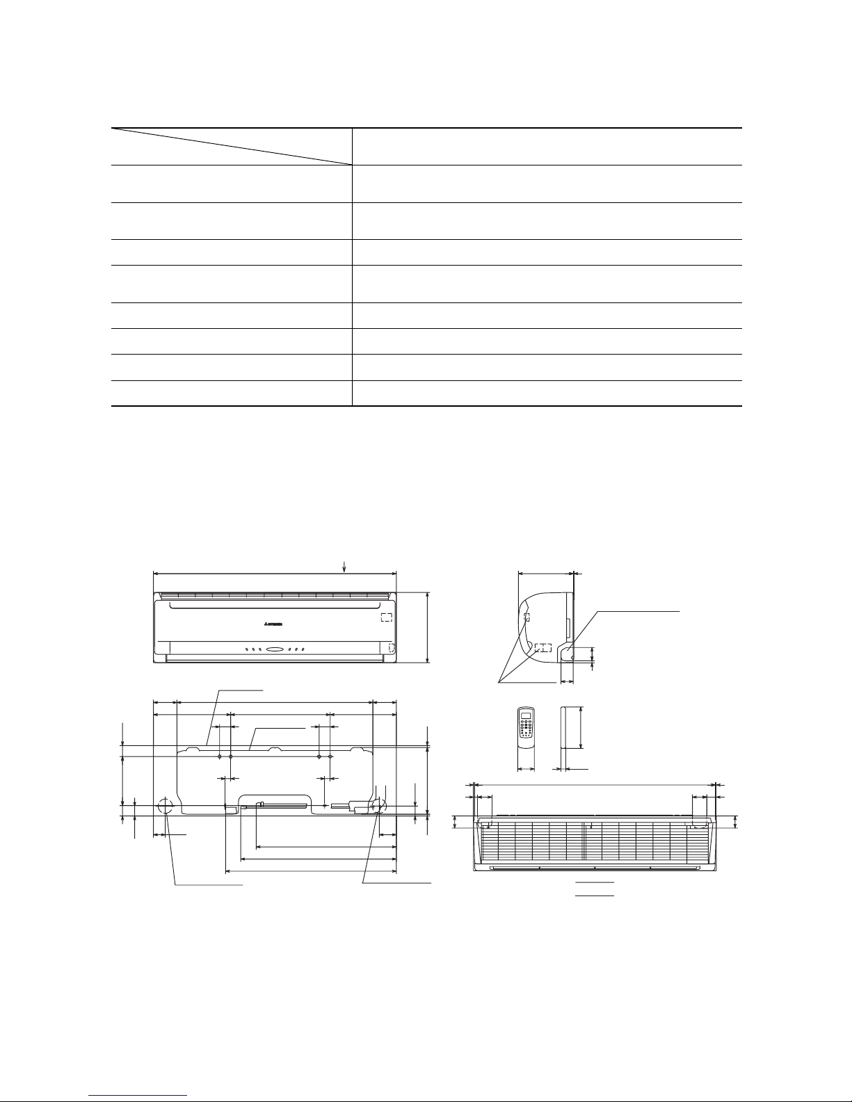
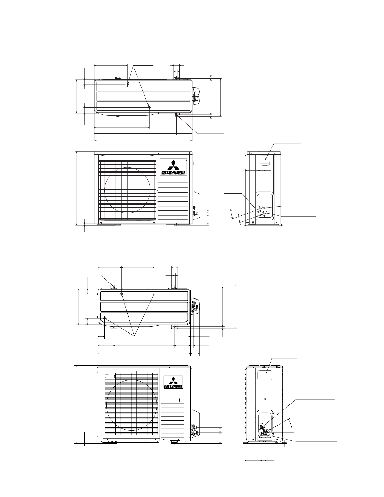
2.3 Exterior dimensions
Indoor return air temperature
(Upper, lower limits)
Refrigerant line (one way) length
All models
Cooling operation: Approximately 21 to 32 °C
Cooling operation: Approximately 21 to 54 °C
Power source voltage Rating ± 10%
Voltage at starting Min. 85% of rating
Max. 25m
Max. 15m
Frequency of ON-OFF cycle Max. 10 times/h
ON and OFF interval Max. 3 minutes
Outdoor air temperature
(Upper, lower limits)
Vertical height difference between
outdoor unit and indoor unit
Item
Models
(1) Indoor unit
Models SRK52CF-BN, 71CF-BN, 52CF-BP, 71CF-BP
VIEW A
A
17.360
150
4
43.5
55
64
489
Piping hole right (left)
3
248
55
4
19 51.2
55
Terminal block
1090
Unit: mm
318
77
44.5
7.7
299
106
8.5301.8
25
50
Installation board
450
50
25
Piping for Gas (ø15.88) 633.5
44.5
53.5
106
49.5
349
886
221.547
Indoor unit
1098
Piping for Liquid (ø6.35) 703.5
Drain hose 772 (ø16)
Piping hole (ø65)
Piping hole (ø65)
-
7
-
Drain holes
286.4
12
50
290
49.6
43.5
850
203.1
510 136.9
476
Elogated hole
(2-12 x16)
314
12
328
Terminal block
Service valve (Liquid)
ø6.35 (1/4'')
Service valve (Gas)
ø15.88 (5/8'')
Ground
terminal
124
34.6
20˚
20˚
42.7
100.3
15
640
14
(2) Outdoor unit
Models SRC52CF-BN, 52CF-BP
Models SRC71CF-BN, 71CF-BP
Unit: mm
38019
24
750
103.5 48.5
580
880
418
340
88
150 150
27
32
310223
47.561
61
2-R7.5
60
15
Drain holes
Service valve(Gas)
Flare fitting ø15.88(5/8")
Service valve (Liquid)
Flare fitting ø6.35(1/4")
Terminal block
30°
165.5 25
Unit: mm
-
8
-
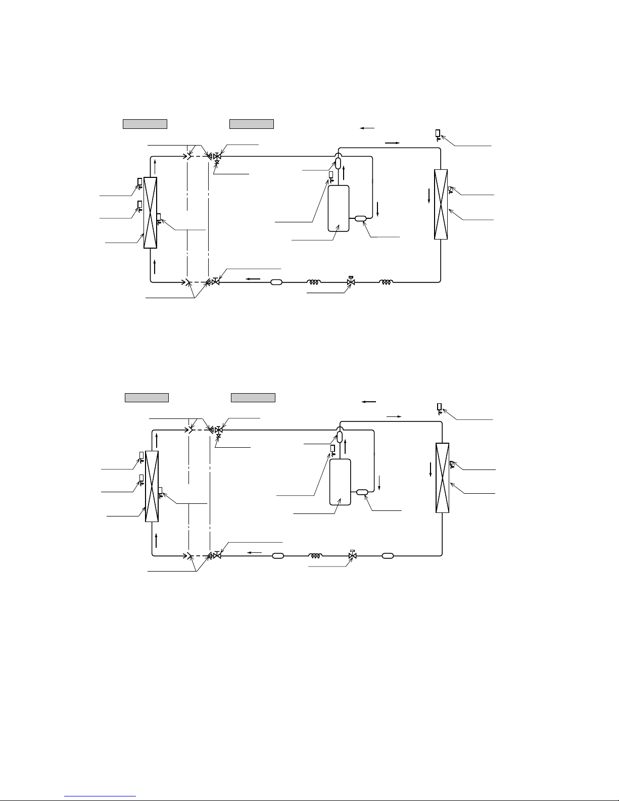
2.4 Piping system
Models SRK52CF-BN, 52CF-BP
Models SRK71CF-BN, 71CF-BP
Outdoor unitIndoor unit
Room temp.
sensor
Humidity
sensor
Heat
exchanger
Flare connecting
Heat
exchanger
sensor
Piping
(Liquid)
ø
6.35
Piping
(Gas)
ø15.88
Check joint
Service valve (Liquid)
Flare connecting
Discharge pipe
temp. sensor
Cooling cycle
Muffler
*
Outdoor air
temp. sensor
Heat
exchanger
Heat exchanger
sensor
Compressor
Capillary tube Capillary tube
Strainer
Accumulator
Service valve
(Gas)
Electronic
expansion valve
* except for 52CF-BN
Outdoor unitIndoor unit
Room temp.
sensor
Humidity
sensor
Heat
exchanger
Flare connecting
Heat
exchanger
sensor
Piping
(Liquid)
ø
6.35
Piping
(Gas)
Check joint
Service valve (Liquid)
Flare connecting
Discharge pipe
temp. sensor
Cooling cycle
Muffler
*
Outdoor air
temp. sensor
Heat
exchanger
Heat exchanger
sensor
Compressor
Capillary tube
Strainer
Strainer
Accumulator
Service valve
(Gas)
Electronic
expansion valve
ø
15.88
* except for 71CF-BP
-
9
-
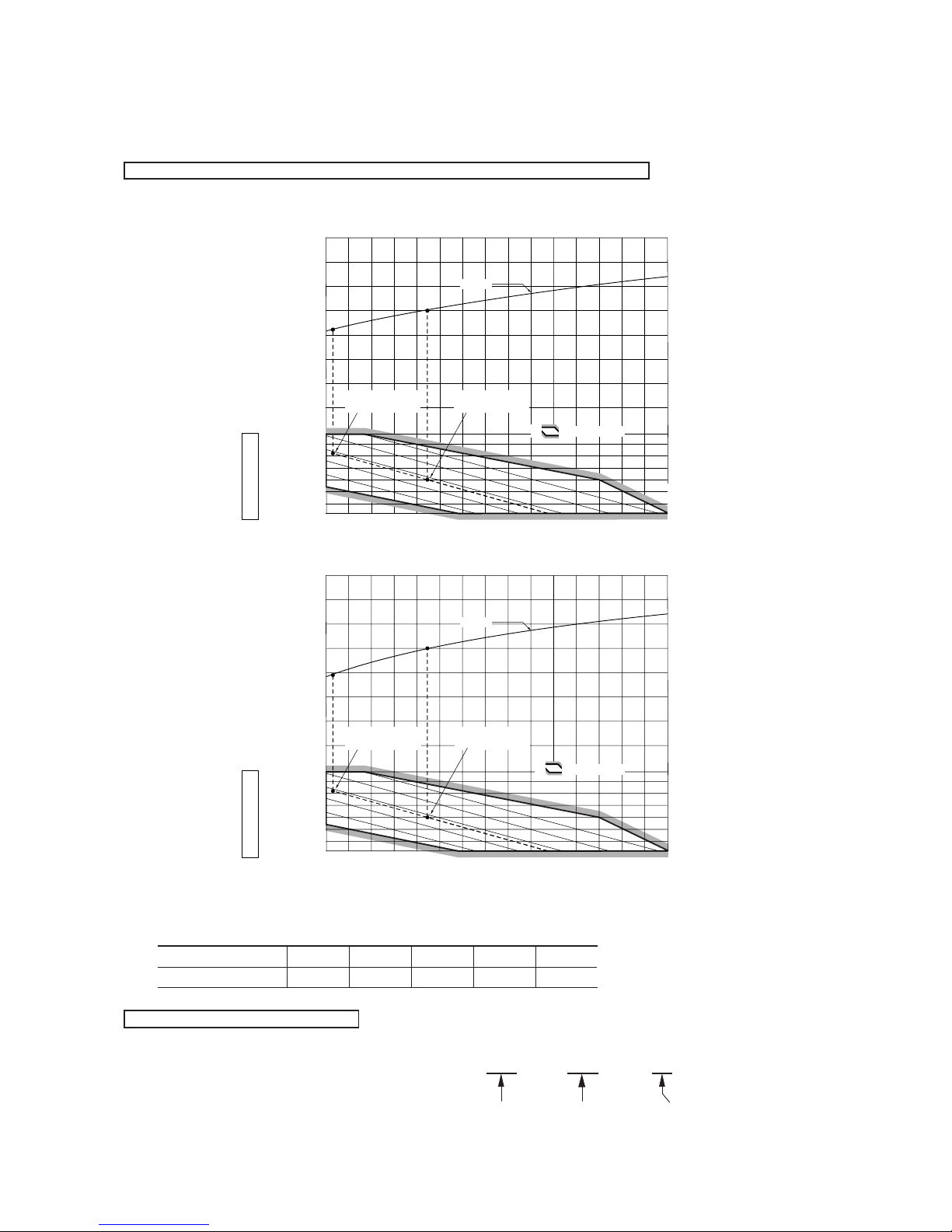
2.5 Selection chart
Correct the cooling capacity in accordance with the conditions as follows. The net cooling capacity can be obtained in the following way.
Net capacity = Capacity shown on specification ✕ Correction factors as follows.
(1) Coefficient of cooling capacity in relation to temperatures
Piping length [m]
Cooling
7
1.0
10
0.99
15
0.975
20
0.965
25
0.95
How to obtain the cooling capacity
Example : The net cooling capacity of the model SRK71CF-BN with the piping length of 15m, indoor wet-bulb temperature at 19.0˚C
and outdoor dry-bulb temperature 35˚C is Net cooling capacity = 7030 ✕ 0.975 ✕ 1.0 = 6854 W
SRK71CF-BN
Length 15m
Factor by air
temperatures
(2) Correction of cooling capacity in relation to one way length of refrigerant piping
It is necessary to correct the cooling capacity in relation to the one way piping length between the indoor and outdoor units.
16 18 20 22
21
25
30
35
40
0.6
0.7
0.8
0.9
1.0
1.1
1.2
1.3
45
50
54
24
Indoor air W.B. temperature °C W.B.
Cooling
Applicable range
Coefficient of cooling
capacity in
relation to temperature
Cooling operation
Outdoor air D.B.
temperature
°C D.B.
ISO-T3
Standard Condition
ISO-T1
Standard Condition
16 18 20 22
21
25
30
35
40
0.6
0.7
0.8
0.9
1.0
1.1
1.2
1.3
45
50
54
24
Indoor air W.B. temperature °C W.B.
Cooling
Applicable range
Coefficient of cooling
capacity in
relation to temperature
Cooling operation
Outdoor air D.B.
temperature
°C D.B.
ISO-T3
Standard Condition
ISO-T1
Standard Condition
S SRK52CF-BN, 52CF-BP
S SRK71CF-BN, 71CF-BP
-
10
-
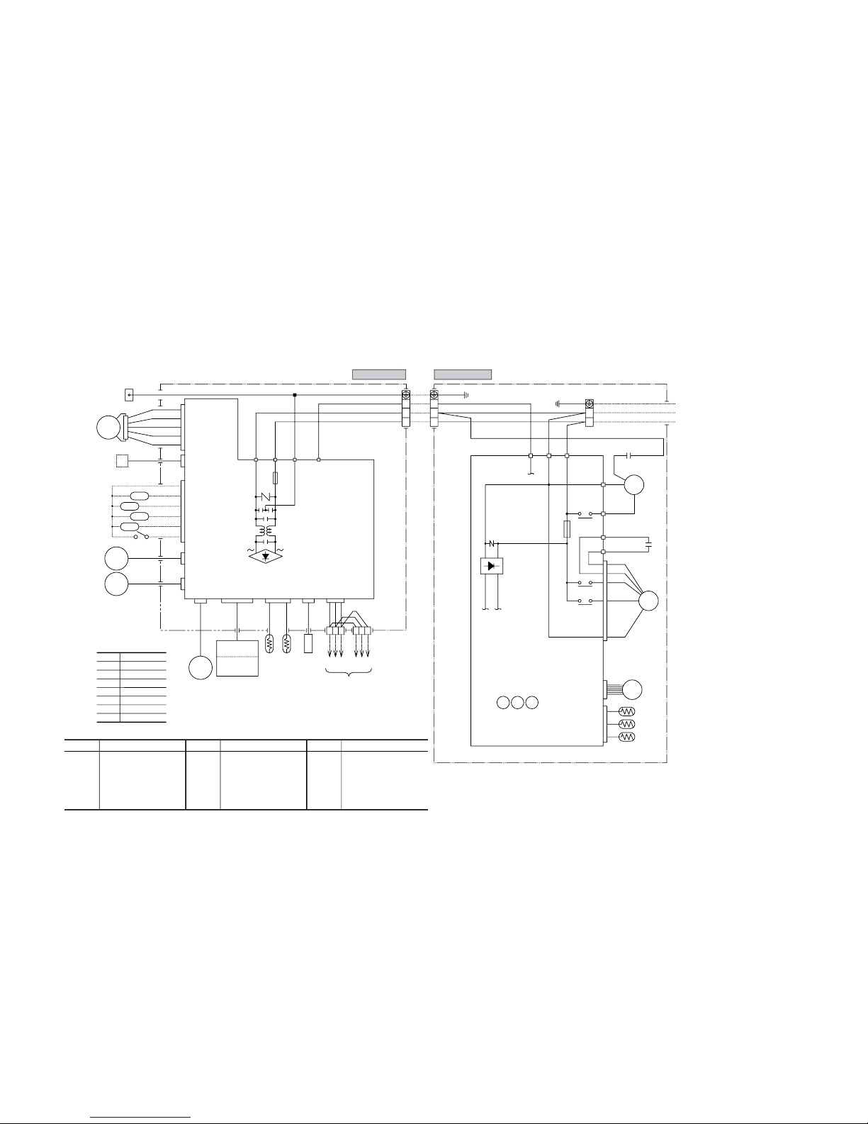
3 ELECTRICAL DATA
3.1 Electrical wiring
Model SRK52-CF-BN
DS
+
~
-
~
J
N
L
CC
11
9
7
3
5
CNU
JEM-A
CNB
CNE CNF
CNM
CNX
CNY
CNT
Option
XR1
XR2
XR3
XR4
XR5
CNG
SM
LM1
LM2
HA
J
RD
Y/GN
G
Y/GN
BK
2/N
1
WH
3
2/N
1
3
L
N
RD
Y/GN
BK
R/LS/N
WH
WH
RD
BK
1
3
Y
BL
4
5
6
ZNR
ZNR
F
250V
3.15A
F
250V
3.15A
Terminal block
TB TB
XZ
Y
XZ
Y
RD
WH
BK
BK
Color symbol
Meaning of marks
Symbol
CM
F
FM
I
FM
O
SM
LM
1,2
Th
1
Th
2
Compressor motor
Fuse
Fan motor(Indoor)
Fan motor(Outdoor)
Flap motor
Louver motor
Room temp.sensor
Heat exch.sensor(Indoor unit)
Capacitor for CM
Capacitor for FM
O
Terminal block
Operation indication (DC12)
Heating indication (DC12)
ON indication for CM(DC12)
Check indication (DC12)
Distant operation
Humidity sensor
Heat exch.sensor(Outdoor unit)
Outdoor air temp.sensor
Discharge pipe temp.sensor
Varistor
Electronic expansion valve
Diode stack
Auxiliary relay
Th
3
Th
4
Th
5
Th
6
ZNR
EEV
DS
52
X1~4
CC
CF
O
TB
XR1
XR2
XR3
XR4
XR5
Parts name
BL
OR
Y/G
Black
Blue
Orange
Yellow/Green
WH White
RD Red
GR Green
Y Yellow
Parts name Parts nameSymbol Symbol
BK
WH
RD
WH
RD
WH
OR
Y
RD
BL
WH
BK
Y
Y
CM2
CM1
W
V
U
52X1
52X3
52X4
Heat
exchanger
To wired
remote
control
(Option)
Power Source
1 Phase
220-240V 50Hz
R-AMP
Wireless
Display
Printed circuit
board
Printed circuit
board
CNU
CNE
CNG
FM
I
CM
52X
1
52X
3
52X
4
EEV
FMo
CF
O
Th4
Th5
Th6
Outdoor unit
Indoor unit
Th3Th2Th1
-
11
-
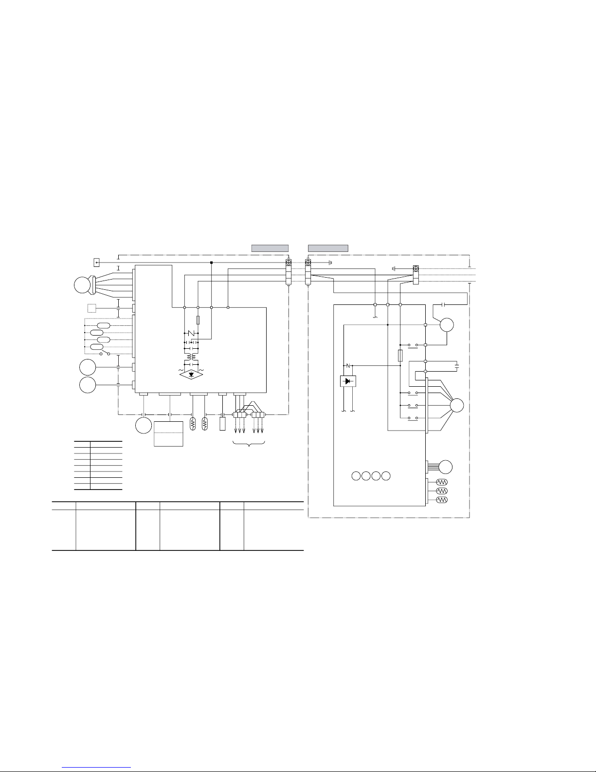
Model SRK71CF-BN
DS
+
-
J
N
L
CC
11
9
7
3
1
5
Option
XR1
XR2
XR3
XR4
XR5
CNE CNFCNM
CNX
CNY
CNT
CNG
SM
LM1
LM2
Heat
HA
J
RD
Y/GN
G
Y/GN
BK
2/N
1
WH
3
2/N
1
3
L
N
RD
Y/GN
BK
R/LS/N
WH
WH
RD
BK
1
3
Y
BL
4
5
6
exchanger
ZNR
ZNR
F
250V
3.15A
F
250V
3.15A
Terminal block
TB TB
XZ
Y
XZ
Y
RD
WH
BK
BK
Color symbol
Meaning of marks
Symbol
CM
F
FM
I
FM
O
SM
LM
1,2
Th
1
Th
2
Compressor motor
Fuse
Fan motor(Indoor)
Fan motor(Outdoor)
Flap motor
Louver motor
Room temp.sensor
Heat exch.sensor(Indoor unit)
Capacitor for CM
Capacitor for FM
O
Terminal block
Operation indication (DC12)
Heating indication (DC12)
ON indication for CM(DC12)
Check indication (DC12)
Distant operation
Humidity sensor
Heat exch.sensor(Outdoor unit)
Outdoor air temp.sensor
Discharge pipe temp.sensor
Varistor
Electronic expansion valve
Diode stack
Auxiliary relay
Th
3
Th
4
Th
5
Th
6
ZNR
EEV
DS
52
X1~5
CC
CF
O
TB
XR1
XR2
XR3
XR4
XR5
Parts name
BL
OR
Y/G
Black
Blue
Orange
Yellow/Green
WH White
RD Red
GR Green
Y Yellow
Parts name Parts nameSymbol Symbol
BK
WH
RD
WH
RD
WH
OR
Y
RD
BL
BK
WH
BK
Y
Y
CM2
CM1
W
V
U
52X1
52X3
52X4
52X5
Power Source
1 Phase
220-240V 50Hz
To wired
remote
control
(Option)
R-AMP
Wireless
Display
board
Printed circuit
Printed circuit
board
CNU
JEM-A
CNB
CNU
CNE
CNG
FM
I
CM
EEV
FMo
CF
O
52X
1
52X
3
52X
4
52X
5
Th4
Th5
Th6
Outdoor unit
Indoor unit
Th3Th2Th1
~~
-
12
-
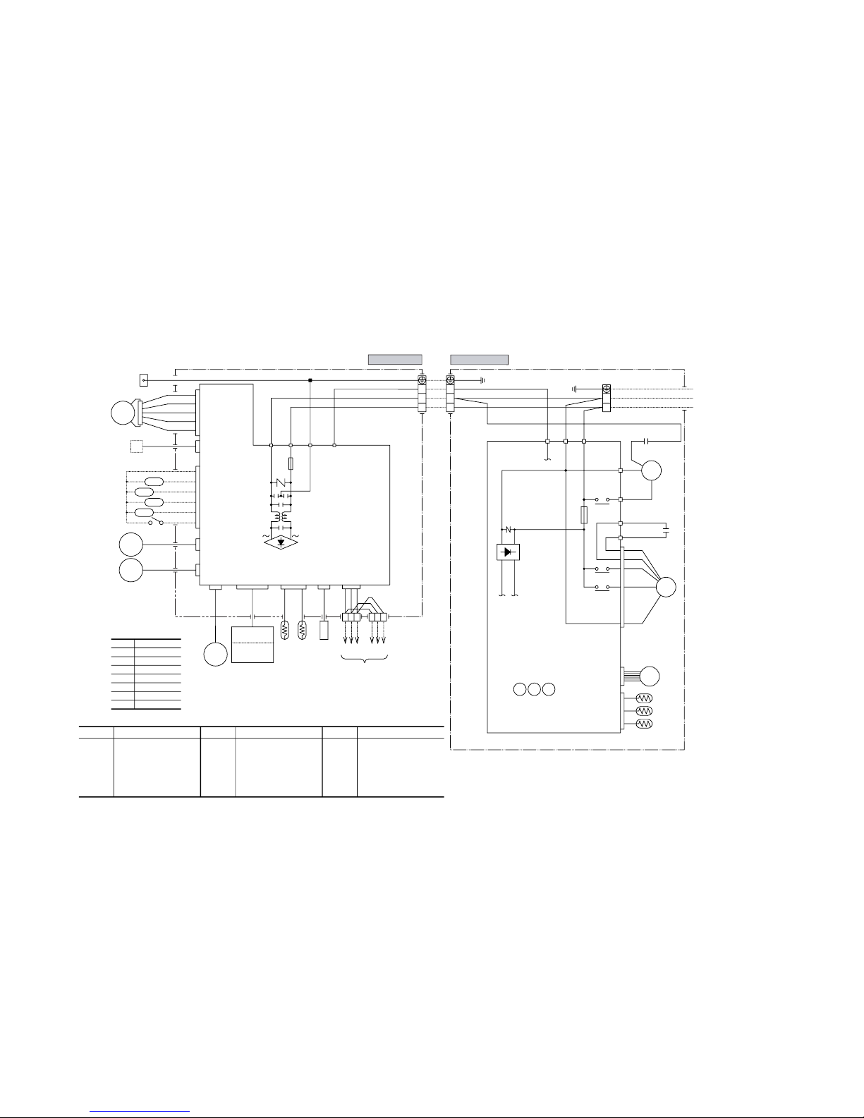
Model SRK52CF-BP
DS
+
~
-
~
J
N
L
CC
11
9
7
3
5
CNU
JEM-A
CNB
CNE CNF
CNM
CNX
CNY
CNT
Option
XR1
XR2
XR3
XR4
XR5
CNG
SM
LM1
LM2
HA
J
RD
Y/GN
G
Y/GN
BK
2/N
1
WH
3
2/N
1
3
L
N
RD
Y/GN
BK
R/LS/N
WH
WH
RD
BK
1
3
Y
BL
4
5
6
ZNR
ZNR
F
250V
3.15A
F
250V
3.15A
Terminal block
TB TB
XZ
Y
XZ
Y
RD
WH
BK
BK
Color symbol
Meaning of marks
Symbol
CM
F
FM
I
FM
O
SM
LM
1,2
Th
1
Th
2
Compressor motor
Fuse
Fan motor(Indoor)
Fan motor(Outdoor)
Flap motor
Louver motor
Room temp.sensor
Heat exch.sensor(Indoor unit)
Capacitor for CM
Capacitor for FM
O
Terminal block
Operation indication (DC12)
Heating indication (DC12)
ON indication for CM(DC12)
Check indication (DC12)
Distant operation
Humidity sensor
Heat exch.sensor(Outdoor unit)
Outdoor air temp.sensor
Discharge pipe temp.sensor
Varistor
Electronic expansion valve
Diode stack
Auxiliary relay
Th
3
Th
4
Th
5
Th
6
ZNR
EEV
DS
52
X1~4
CC
CF
O
TB
XR1
XR2
XR3
XR4
XR5
Parts name
BL
OR
Y/G
Black
Blue
Orange
Yellow/Green
WH White
RD Red
GR Green
Y Yellow
Parts name Parts nameSymbol Symbol
BK
WH
RD
WH
RD
WH
OR
Y
RD
BL
WH
BK
Y
Y
CM2
CM1
W
V
U
52X1
52X3
52X4
Heat
exchanger
To wired
remote
control
(Option)
Power Source
1 Phase
220V 60Hz
R-AMP
Wireless
Display
Printed circuit
board
Printed circuit
board
CNU
CNE
CNG
FM
I
CM
52X
1
52X
3
52X
4
EEV
FMo
CF
O
Th4
Th5
Th6
Outdoor unit
Indoor unit
Th3Th2Th1
-
13
-
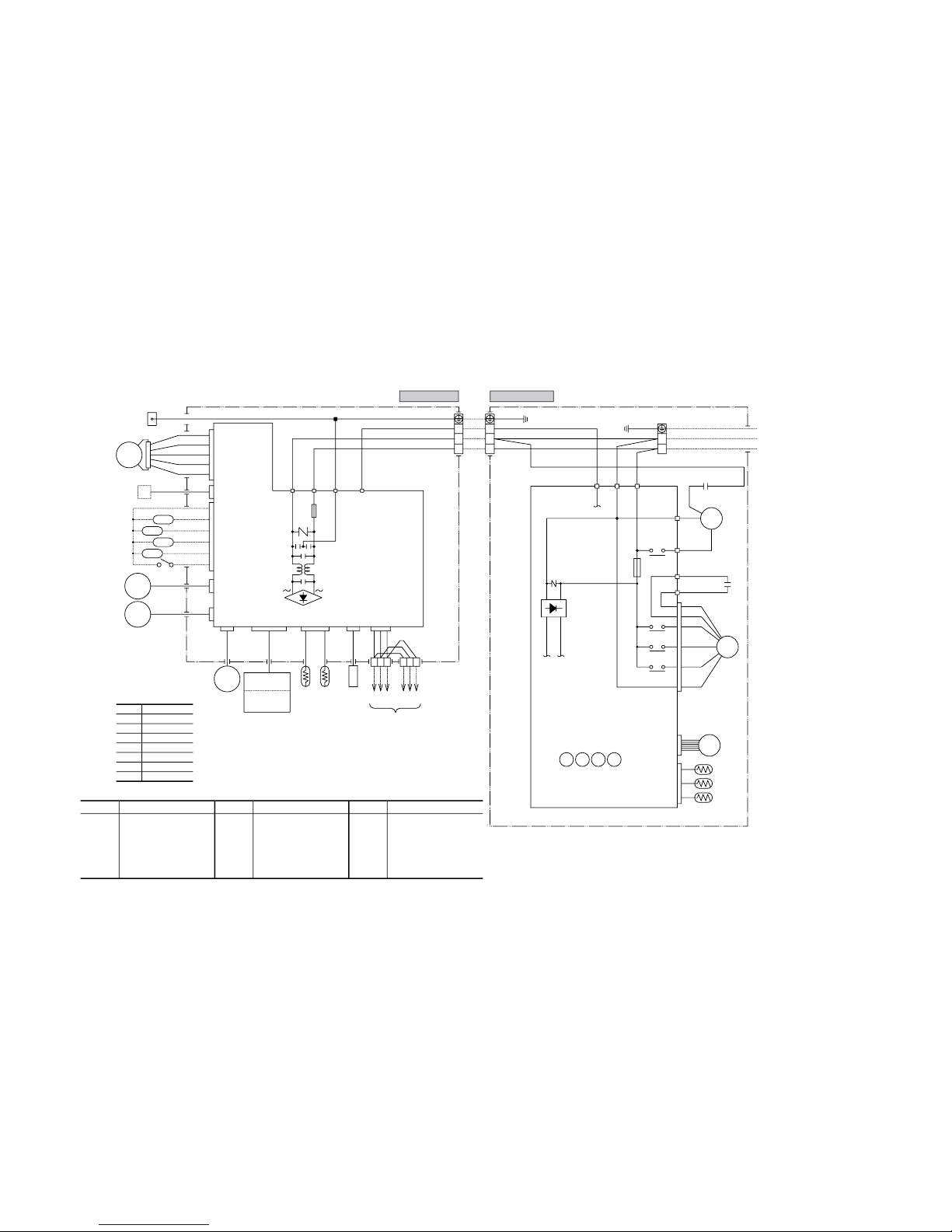
Model SRK71CF-BP
DS
+
-
J
N
L
CC
11
9
7
3
1
5
Option
XR1
XR2
XR3
XR4
XR5
CNE CNFCNM
CNX
CNY
CNT
CNG
SM
LM1
LM2
Heat
HA
J
RD
Y/GN
G
Y/GN
BK
2/N
1
WH
3
2/N
1
3
L
N
RD
Y/GN
BK
R/LS/N
WH
WH
RD
BK
1
3
Y
BL
4
5
6
exchanger
ZNR
ZNR
F
250V
3.15A
F
250V
3.15A
Terminal block
TB TB
XZ
Y
XZ
Y
RD
WH
BK
BK
Color symbol
Meaning of marks
Symbol
CM
F
FM
I
FM
O
SM
LM
1,2
Th
1
Th
2
Compressor motor
Fuse
Fan motor(Indoor)
Fan motor(Outdoor)
Flap motor
Louver motor
Room temp.sensor
Heat exch.sensor(Indoor unit)
Capacitor for CM
Capacitor for FM
O
Terminal block
Operation indication (DC12)
Heating indication (DC12)
ON indication for CM(DC12)
Check indication (DC12)
Distant operation
Humidity sensor
Heat exch.sensor(Outdoor unit)
Outdoor air temp.sensor
Discharge pipe temp.sensor
Varistor
Electronic expansion valve
Diode stack
Auxiliary relay
Th
3
Th
4
Th
5
Th
6
ZNR
EEV
DS
52
X1~5
CC
CF
O
TB
XR1
XR2
XR3
XR4
XR5
Parts name
BL
OR
Y/G
Black
Blue
Orange
Yellow/Green
WH White
RD Red
GR Green
Y Yellow
Parts name Parts nameSymbol Symbol
BK
WH
RD
WH
RD
WH
OR
Y
RD
BL
BK
WH
BK
Y
Y
CM2
CM1
W
V
U
52X1
52X3
52X4
52X5
Power Source
1 Phase
220V 60Hz
To wired
remote
control
(Option)
R-AMP
Wireless
Display
board
Printed circuit
Printed circuit
board
CNU
JEM-A
CNB
CNU
CNE
CNG
FM
I
CM
EEV
FMo
CF
O
52X
1
52X
3
52X
4
52X
5
Th4
Th5
Th6
Outdoor unit
Indoor unit
Th3Th2Th1
~~
-
14
-
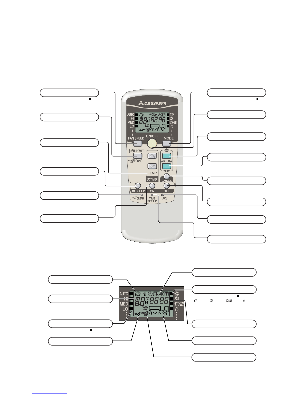
S Indication section
Models All models
S Operation section
4. OUTLINE OF OPERATION CONTROL BY MICROCOMPUTER
4.1 Operation control function by remote control switch
(1) Wireless remote control
FAN SPEED button
Each time the button is pushed, the indicator is switched over in turn.
• The above illustration shows all controls, but in practice
only the relevant parts are shown.
OPERATION MODE select button
Each time the button is pushed, the indicator is switched over in turn.
ON/OFF (luminous) button
Press for starting operation, press again for
stopping.
HI POWER/ECONO button
This button changes the HIGH POWER/
ECONOMY mode.
AIR FLOW (UP/DOWN) button
This button changes the air flow (up/down)
mode.
TIME SET UP switch
This switch for setting the time.
SLEEP button
This button selects SLEEP operation.
CLEAN switch
This switch changes the CLEAN mode.
ON TIMER button
This button selects ON TIMER operation.
TEMPERATURE button
This button sets the room temperature.
(This button changes the present time and
TIMER time.)
OFF TIMER button
This button selects OFF TIMER operation.
RESET switch
Switch for resetting microcomputer.
OPERATION MODE indicator
Indicates selected operation with lamp.
[ (Auto) • (Cool) • (Fan) • (Dry)]
TEMPERATURE indicator
Indicates set temperature.
(Does not indicate temperature when operation
mode is on AUTO)
FAN SPEED indicator
Indicates set air flow rate with lamp.
CLEAN indicator
Indicates during CLEAN operation.
SLEEP indicator
Indicates during SLEEP operation.
ON/OFF TIMER indicator
Indicates during ON/OFF TIMER operation.
TIME indicator
Indicates present time or timer setting time.
AIR FLOW indicator
Shows selected flap and louver mode.
AIR FLOW (LEFT/RIGHT) button
This button changes the air flow (left/right)
mode.
CANCEL button
This button cancels the ON timer, OFF
timer, and SLEEP operation.
HI POWER/ ECONO MODE indicator
Indicates during High power/economy mode
operation.
-
15
-
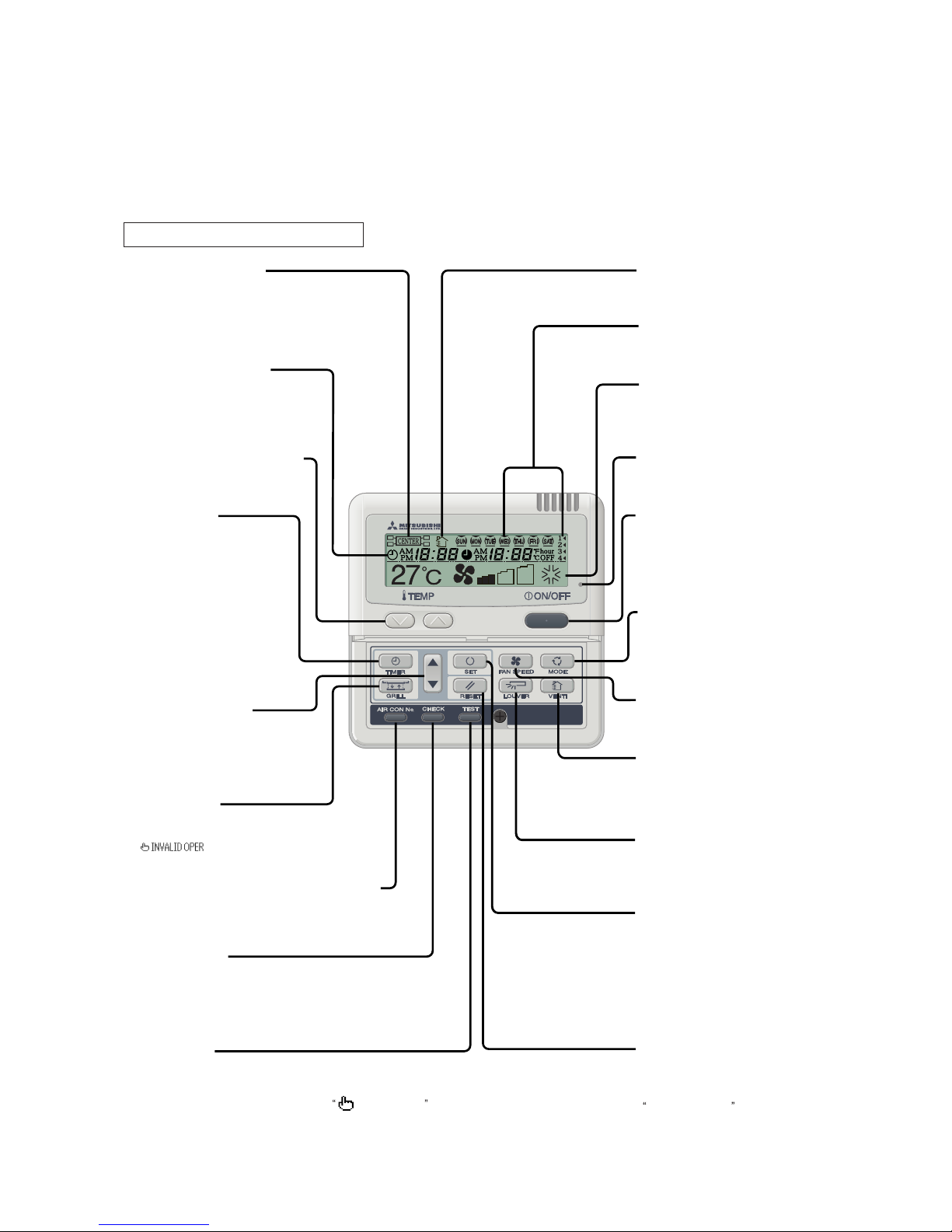
(2) Wired remote control (Optional parts)
The figure below shows the remote control with the cover opened. Note that all the items that may be displayed in the liquid crystal display
area are shown in the figure for the sake of explanation.
Characters displayed with dots in the liquid crystal display area are abbreviated.
Pull the cover downward to open it.
Weekly timer display
Displays the settings of
the weekly timer.
[Vent indicator]
Indicates operation in the
ventilation mode.
Operation/Stop switch
This switch is used to operate and
stop the air conditioning system.
Press the switch once to operate
the system and press it once again to
stop the system.
MODE switch
This switch is used to switch between
operation modes.
(The clean operation cannot be selected.)
Operation setting display area
Displays setting temperature,
airflow volume, operation mode and
operation message.
Operation/Check indicator light
During operation: Lit in green
In case of error: Flashing in red
FAN SPEED switch
This switch is used to set the
airflow volume.
(AUTO, HI POWER or ECONO
cannot be selected.)
SET switch
This switch is used to apply the timer
operation setting.
This switch is also used to make silent
mode operation settings.
[RESET switch]
Press this switch while making settings
to go back to the previous operation.
This switch is also used to reset the
FILTER CLEANING message display.
(Press this switch after cleaning the air filter.)
Central control display
Displayed when the air conditioning
system is controlled by the option controller.
Timer operation display
Displays the settings related to
timer operation.
AIR CON No. (Air conditioning system No.) switch
Displays the number of the connected
air conditioning system.
("00" appears.)
[CHECK switch]
This switch is used at servicing.
[TEST switch]
This switch is used during test operation.
Temperature setting switches
These switches are used to set
the temperature of the room.
[VENT switch]
Switch that operates the
connected ventilator.
Timer setting switches
These switches are used to set
the timer mode and time.
TIMER switch
This switch is used to select
a timer mode.
(The comfortable timer or sleep
operation cannot be selected.)
[GRILL switch]
This switch has no function.
When this switch is pressed,
(Invalid Operation)
is displayed, but it does not mean a failure.
LOUVER switch
This switch is used to operate/stop
the swing louver.
(UP/down swing only)
* If you press any of the switches above and INVALID OPER is display, the switch has no function.
But it does not mean a failure.
Note (1) The SRK models don't support the switches and functions displayed in [ ].
 Loading...