

Mitsubishi Heavy Industries SRK63ZE-S1, SRK25ZD-S1, SRK35ZD-S1, SRK50ZD-S1, SRK71ZE-S1 Technical Manual
...
-
3
-
INVERTER WALL MOUNTED TYPE ROOM AIR-CONDITIONER
( Split system, air to air heat pump type )
SRK20ZD-S1, SRK25ZD-S1, SRK35ZD-S1, SRK50ZD-S1
SRK63ZE-S1, SRK71ZE-S1
WALL MOUNTED TYPE ROOM AIR-CONDITIONER
( Split system, air to air heat pump type )
SRK20HD-S1, SRK28HD-S1, SRK40HD-S1
SRK20HC-S2, SRK28HC-S2, SRK40HC-S2
SRK50HE-S1, SRK56HE-S1
SRK63HE-S1, SRK71HE-S1
WALL MOUNTED TYPE ROOM AIR-CONDITIONER
( Split system, air cooled cooling only type )
SRK20CD-S1, SRK28CD-S1, SRK40CD-S1
SRK20CC-S1, SRK28CC-S1, SRK40CC-S1
SRK50CE-S1, SRK56CE-S1
SRK63CE-S1, SRK71CE-S1
Manual No. ’06
.
SRK-T
.
050
updated September 29, 2009

TABLE OF CONTENTS
1. INVERTER WALL MOUNTED TYPE ROOM AIR-CONDITIONER
(Split system, air to air heat pump type) ...................................................................... 001
2. WALL MOUNTED TYPE ROOM AIR-CONDITIONER
(Split system, air to air heat pump type) ...................................................................... 137
3. WALL MOUNTED TYPE ROOM AIR-CONDITIONER
(Split system, air cooled cooling only type) ................................................................. 261

-
1
-
1.1 SRK20ZD-S1
SRK25ZD-S1
SRK35ZD-S1
SRK50ZD-S1 ............................................................ 2
1.2 SRK63ZE-S1
SRK71ZE-S1............................................................. 70
1. INVERTER WALL MOUNTED TYPE
ROOM AIR-CONDITIONER
Split system, air to air
heat pump type
( )

-
2
-
CONTENTS
1.1.1 GENERAL INFORMATION....................................................................... 3
(1) Specific features.................................................................................... 3
(2) How to read the model name................................................................ 3
1.1.2 SELECTION DATA.................................................................................... 4
(1) Specifications ........................................................................................ 4
(2) Range of usage & limitations ............................................................... 8
(3) Exterior dimensions.............................................................................. 8
(4) Piping system ........................................................................................ 10
(5) Selection chart....................................................................................... 11
1.1.3 ELECTRICAL DATA ................................................................................. 12
(1) Electrical wiring..................................................................................... 12
1.1.4 OUTLINE OF OPERATION CONTROL BY MICROCOMPUTER ............ 14
(1) Operation control function by remote control switch ....................... 14
(2) Unit ON/OFF button............................................................................... 15
(3) Power blackout auto restart function.................................................. 15
(4) Flap control............................................................................................ 16
(5) Comfortable timer setting..................................................................... 16
(6) Outline of heating operation ................................................................ 17
(7) Outline of cooling operation ................................................................ 19
(8) Outline of dehumidifying operation..................................................... 20
(9) Outline of automatic operation ............................................................22
(10) Economical operation ........................................................................... 22
(11) Protective control function................................................................... 22
1.1.5 APPLICATION DATA ................................................................................ 28
(1) Selection of location for installation ................................................... 29
(2) Installation of indoor unit .....................................................................30
(3) Installation of outdoor unit ................................................................... 32
(4) Refrigerant piping ................................................................................. 32
(5) Test run................................................................................................... 34
(6) Precautions for wireless remote controller installation and
operation ................................................................................................35
1.1.6 MAINTENANCE DATA .............................................................................36
(1) Troubleshooting procedures for electrical equipment ...................... 36
(2) Servicing ................................................................................................ 54
1.1.7 REFRIGERANT PIPING INSTALLATION/SERVICING MANUAL
FOR AIR CONDITIONERS USING R410A............................................... 55
(1) Outline ....................................................................................................55
(2) Refrigerant piping installation ............................................................. 56
(3) Installation, removal and servicing ..................................................... 62
(4) Refrigerant recovery ............................................................................. 67
-
3
-
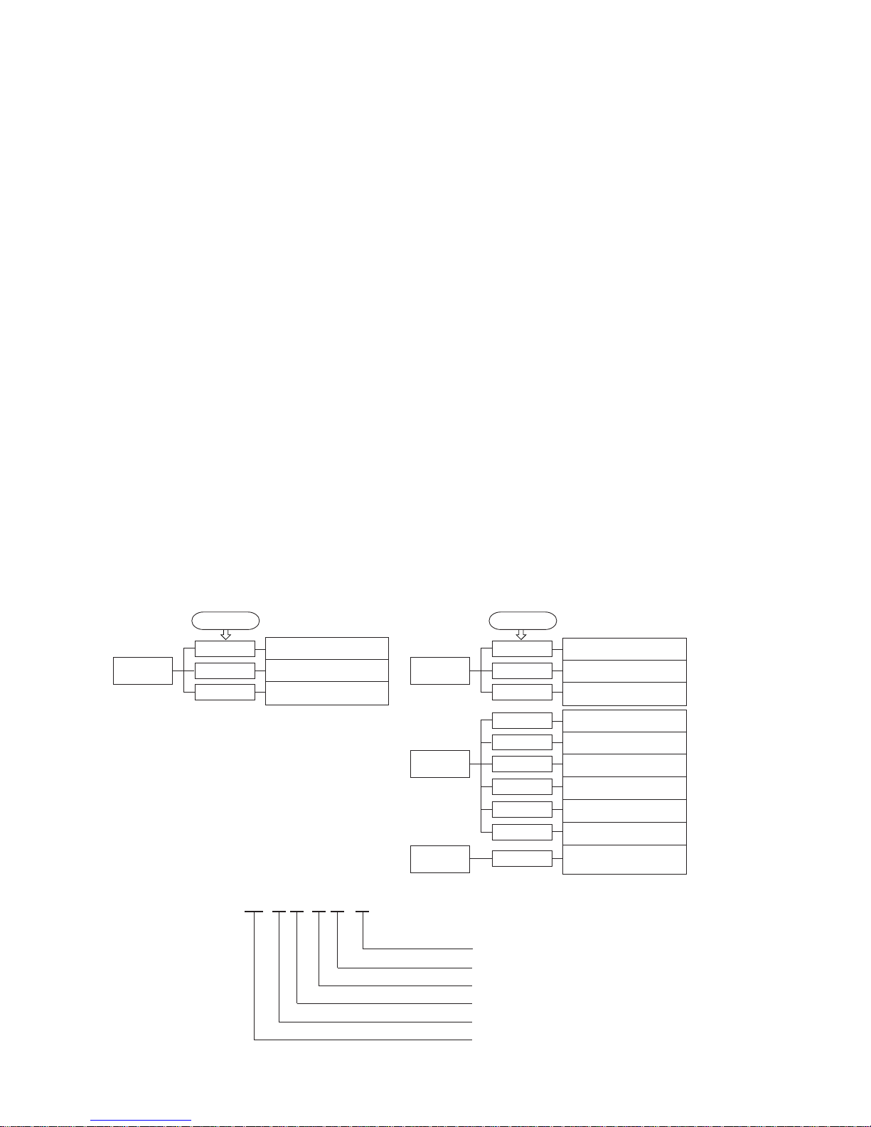
Over heat of compressor
Error of signal transmission
Outdoor fan motor error
1.1.1 GENERAL INFORMATION
(1) Specific features
The “MITSUBISHI HEAVY INDUSTRIES, LTD” room air-conditioner: SRK series are of split and wall mounted type and the unit
consists of indoor unit and outdoor unit with refrigerant precharged in factory. The indoor unit is composed of room air cooling or
heating equipment with operation control switch and the outdoor unit is composed of condensing unit with compressor.
(a) Inverter (Frequency converter) for multi-steps power control
¡ Heating/Cooling
The rotational speed of a compressor is changed in step in relation to varying load, interlocked with the indoor and outdoor unit
fans controlled to change frequency, thus controlling the capacity.
¡ Allowing quick heating/cooling operation during start-up period. Constant room temperature by fine-tuned control after the
unit has stabilized.
(b) Fuzzy control
¡ Fuzzy control calculates the amount of variation in the difference between the return air temperature and the setting temperature
in compliance with the fuzzy rules in order to control the air capacity and the inverter frequency.
(c) Remote control flap
The flap can be automatically controlled by operating wireless remote control.
¡ Air scroll (AUTO): Flap operation is automatically control.
¡ Swing: This will swing the flap up and down.
¡ Memory flap: Once the flap position is set, the unit memorizes the position and continues to operate at the same position from
the next time.
(d) Self diagnosis function
¡ We are constantly trying to do better service to our customers by installing such judges that show abnormality of operation as
follows.
Outdoor heat exchanger liquid
pipe sensor error
Discharge pipe sensor error
Outdoor temperature sensor error
2 time flash
4 time flash
RUN light
keeps flashing
1 time flash
Trouble of outdoor unit
Over current
Current cut
2 time flash
3 time flash
RUN light
ON
1 time flash
5 time flash
TIMER light
R410A models
Series No.
Inverter type
Product capacity
Wall mounted type
Split type room air-conditioner
(2) How to read the model name
Example : SR K 35 Z D - S1
Room temperature sensor error
Indoor fan motor error
Heat exchanger sensor error
2 time flash
6 time flash
TIMER light
ON
1 time flash
RUN light
Rotor lock
6 time flash
7 time flash
2 time flash
RUN light
2 time flash
-
4
-
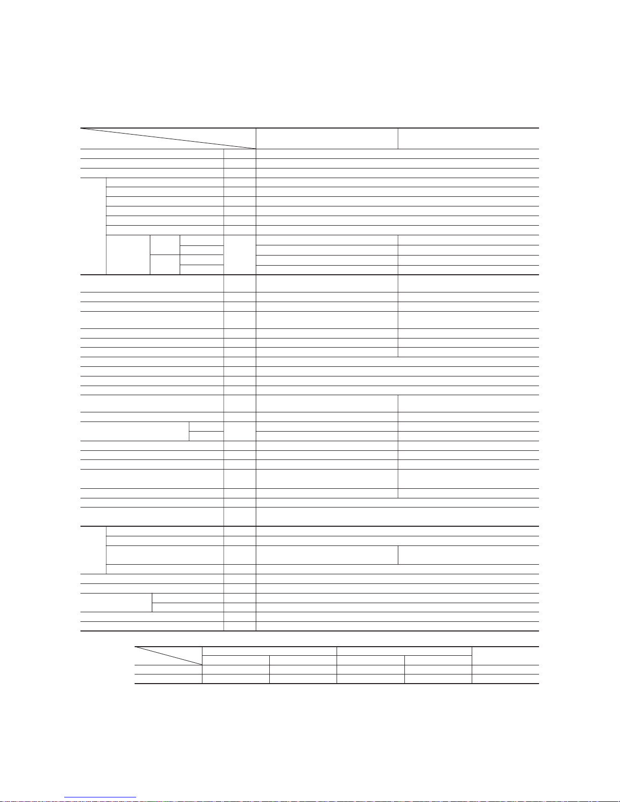
Item
Model
SRK20ZD-S1 SRC20ZD-S1
Cooling capacity
(1)
W 2000 (500~2800)
Heating capacity
(1)
W 2700 (500~4600)
Power source 1 Phase, 220-240V, 50Hz
Cooling input kW 0.44 (0.1~0.91)
Running current (Cooling) A 2.4/2.3/2.2
Heating input kW 0.62 (0.09~1.27)
Running current (Heating) A 3.0/2.9/2.8
Inrush current A 3.0/2.9/2.8
COP Cooling: 4.55 Heating: 4.35
Cooling
Sound level Hi 36, Me 29, Lo 21 44
Noise level
Power level
dB
52 58
Heating
Sound level Hi 38, Me 32, Lo 25 47
Power level 54 61
Exterior dimensions
Height × Width × Depth
mm
250 × 815 × 249 540 × 720 × 290
Color Cool white Stucco white
Net weight kg 9.0 32
Refrigerant equipment
Compressor type & Q’ty
– RM-B5077MD1 (Rotary type) × 1
Motor kW – 0.75
Starting method – Line starting
Heat exchanger Louver fins & inner grooved tubing Straight fins & inner grooved tubing
Refrigerant control Capillary tubes + Electronic expansion valve
Refrigerant
(3)
kg R410A 0.9 (Pre-Charged up to the piping length of 15m)
Refrigerant oil R 0.35 (MA68)
Deice control Microcomputer control
Air handling equipment
Fan type & Q’ty
Tangential fan × 1 Propeller fan × 1
Motor W 29 24
(Cooling) 7.2 30
Air flow (at High)
(Heating)
CMM
8.3 25
Air filter, Q’ty Polypropylene net (washable) × 2–
Shock & vibration absorber – Cushion rubber (for compressor)
Electric heater ––
Operation control
Operation switch
Wireless-Remote controller –
Room temperature control Microcomputer thermostat –
Pilot lamp RUN (Green), TIMER (Yellow), HI POWER (Green), ECONO (Orange)
Safety equipment
O.D mm (in) Liquid line: φ6.35 (1/4″) Gas line: φ9.52 (3/8″)
Connecting method Flare connecting
Attached length of piping Liquid line: 0.47 m
Gas line : 0.40 m
–
Insulation Necessary (Both sides)
Drain hose Connectable
Power source cord 2.5 m (3 cores with Earth)
Size × Core number 1.5 mm2 × 4 cores (Including earth cable)
Connection wiring
Connecting method Terminal block (Screw fixing type)
Accessories (included)
Mounting kit, Clean filter (Natural enzyme filter x1, Photocatalytic washable deodorizing filter x1)
Optional parts –
Notes (1) The data are measured at the following conditions.
1.1.2 SELECTION DATA
(1) Specifications
Model SRK20ZD-S1 (Indoor unit)
SRC20ZD-S1 (Outdoor unit)
Item Indoor air temperature Outdoor air temperature
Standards
Operation DB WB DB WB
Cooling 27ºC 19ºC 35ºC 24ºC ISO-T1, JIS C9612
Heating 20ºC – 7ºC 6ºC ISO-T1, JIS C9612
(2) The operation data are applied to the 220/230/240V districts respectively.
(3) The refrigerant quantity to be charged includes the refrigerant in 15 m connecting piping.
(Purging is not required even for the short piping.)
Operation data
(1)
Refrigerant
piping
Compressor overheat protection, Heating overload protection (High pressure control), Overcurrent protection,
Frost protection, Serial signal error protection, Indoor fan motor error protection, Cooling overload protection
The piping length is 7.5m.
(220/230/240V)

-
5
-
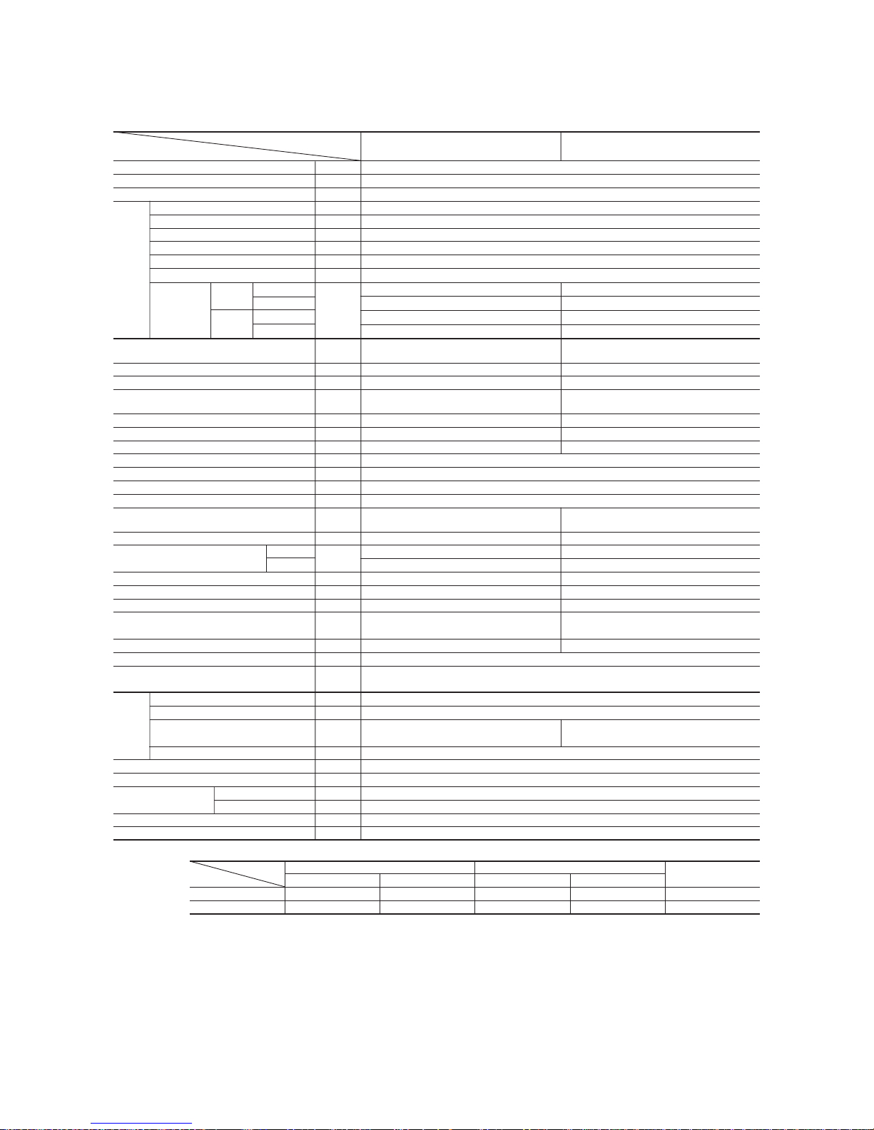
Item
Model
SRK25ZD-S1 SRC25ZD-S1
Cooling capacity
(1)
W 2500 (500~3000)
Heating capacity
(1)
W 3400 (500~4800)
Power source 1 Phase, 220-240V, 50Hz
Cooling input kW 0.62 (0.1~0.97)
Running current (Cooling) A 3.1/3.0/2.9
Heating input kW 0.94 (0.09~1.30)
Running current (Heating) A 4.5/4.3/4.1
Inrush current A 4.5/4.3/4.1
COP Cooling: 4.03 Heating: 3.62
Cooling
Sound level Hi 37, Me 30, Lo 22 44
Noise level
Power level
dB
53 58
Heating
Sound level Hi 39, Me 33, Lo 26 47
Power level 55 61
Exterior dimensions
Height × Width × Depth
mm
250 × 815 × 249 540 × 720 × 290
Color Cool white Stucco white
Net weight kg 9.0 32
Refrigerant equipment
Compressor type & Q’ty
– RM-B5077MD1 (Rotary type) × 1
Motor kW – 0.75
Starting method – Line starting
Heat exchanger Louver fins & inner grooved tubing Straight fins & inner grooved tubing
Refrigerant control Capillary tubes + Electronic expansion valve
Refrigerant
(3)
kg R410A 0.9 (Pre-Charged up to the piping length of 15m)
Refrigerant oil R 0.35 (MA68)
Deice control Microcomputer control
Air handling equipment
Fan type & Q’ty
Tangential fan × 1 Propeller fan × 1
Motor W 29 24
(Cooling) 8.0 30
Air flow (at High)
(Heating)
CMM
8.7 25
Air filter, Q’ty Polypropylene net (washable) × 2–
Shock & vibration absorber – Cushion rubber (for compressor)
Electric heater ––
Operation control
Operation switch
Wireless-Remote controller –
Room temperature control Microcomputer thermostat –
Pilot lamp RUN (Green), TIMER (Yellow), HI POWER (Green), ECONO (Orange)
Safety equipment
O.D mm (in) Liquid line: φ6.35 (1/4″) Gas line: φ9.52 (3/8″)
Connecting method Flare connecting
Attached length of piping Liquid line: 0.47 m
Gas line : 0.40 m
–
Insulation Necessary (Both sides)
Drain hose Connectable
Power source cord 2.5 m (3 cores with Earth)
Size × Core number 1.5 mm2 × 4 cores (Including earth cable)
Connection wiring
Connecting method Terminal block (Screw fixing type)
Accessories (included)
Mounting kit, Clean filter (Natural enzyme filter x1, Photocatalytic washable deodorizing filter x1)
Optional parts –
Notes (1) The data are measured at the following conditions.
Model SRK25ZD-S1 (Indoor unit)
SRC25ZD-S1 (Outdoor unit)
Item Indoor air temperature Outdoor air temperature
Standards
Operation DB WB DB WB
Cooling 27ºC 19ºC 35ºC 24ºC ISO-T1, JIS C9612
Heating 20ºC – 7ºC 6ºC ISO-T1, JIS C9612
(2) The operation data are applied to the 220/230/240V districts respectively.
(3) The refrigerant quantity to be charged includes the refrigerant in 15 m connecting piping.
(Purging is not required even for the short piping.)
Operation data
(1)
Refrigerant
piping
Compressor overheat protection, Heating overload protection (High pressure control), Overcurrent protection,
Frost protection, Serial signal error protection, Indoor fan motor error protection, Cooling overload protection
The piping length is 7.5m.
(220/230/240V)

-
6
-
Item
Model
SRK35ZD-S1 SRC35ZD-S1
Cooling capacity
(1)
W 3500 (500~3900)
Heating capacity
(1)
W 4500 (500~5100)
Power source 1 Phase, 220-240V, 50Hz
Cooling input kW 1.09 (0.1~1.22)
Running current (Cooling) A 5.4/5.2/5.0
Heating input kW 1.24 (0.09~1.32)
Running current (Heating) A 5.9/5.7/5.4
Inrush current A 5.9/5.7/5.4
COP Cooling: 3.21 Heating: 3.63
Cooling
Sound level Hi 41, Me 32, Lo 23 48
Noise level
Power level
dB
58 62
Heating
Sound level Hi 45, Me 36, Lo 27 50
Power level 59 64
Exterior dimensions
Height × Width × Depth
mm
250 × 815 × 249 540 × 720 × 290
Color Cool white Stucco white
Net weight kg 9.0 35
Refrigerant equipment
Compressor type & Q’ty
– RM-B5077MD1 [Rotary type] × 1
Motor kW – 0.90
Starting method – Line starting
Heat exchanger Louver fins & inner grooved tubing Straight fins & inner grooved tubing
Refrigerant control Capillary tubes + Electronic expansion valve
Refrigerant
(3)
kg R410A 1.1 (Pre-Charged up to the piping length of 15m)
Refrigerant oil R 0.35 (MA68)
Deice control Microcomputer control
Air handling equipment
Fan type & Q’ty
Tangential fan × 1 Propeller fan × 1
Motor W 29 24
(Cooling) 8.9 34
Air flow (at High)
(Heating)
CMM
10.3 34
Air filter, Q’ty
Polypropylene net (washable) × 2
–
Shock & vibration absorber – Cushion rubber (for compressor)
Electric heater ––
Operation control
Operation switch
Wireless-Remote controller –
Room temperature control Microcomputer thermostat –
Pilot lamp RUN (Green), TIMER (Yellow), HI POWER (Green), ECONO (Orange)
Safety equipment
O.D mm (in) Liquid line: φ6.35 (1/4″) Gas line: φ9.52 (3/8″)
Connecting method Flare connecting
Attached length of piping Liquid line: 0.47 m
Gas line : 0.40 m
–
Insulation Necessary (Both sides)
Drain hose Connectable
Power source cord 2.5 m (3 cores with Earth)
Size × Core number 1.5 mm2 × 4 cores (Including earth cable)
Connection wiring
Connecting method Terminal block (Screw fixing type)
Accessories (included)
Mounting kit, Clean filter (Natural enzyme filter x1, Photocatalytic washable deodorizing filter x1)
Optional parts –
Notes (1) The data are measured at the following conditions.
Model SRK35ZD-S1 (Indoor unit)
SRC35ZD-S1 (Outdoor unit)
Item Indoor air temperature Outdoor air temperature
Standards
Operation DB WB DB WB
Cooling 27ºC 19ºC 35ºC 24ºC ISO-T1, JIS C9612
Heating 20ºC – 7ºC 6ºC ISO-T1, JIS C9612
(2) The operation data are applied to the 220/230/240V districts respectively.
(3) The refrigerant quantity to be charged includes the refrigerant in 15 m connecting piping.
(Purging is not required even for the short piping.)
Operation data
(1)
Refrigerant
piping
Compressor overheat protection, Heating overload protection (High pressure control), Overcurrent protection,
Frost protection, Serial signal error protection, Indoor fan motor error protection, Cooling overload protection
The piping length is 7.5m.
(220/230/240V)
-
7
-
Model SRK50ZD-S1 (Indoor unit)
SRC50ZD-S1 (Outdoor unit)
Item
Model
SRK50ZD-S1 SRC50ZD-S1
Cooling capacity
(1)
W 5000 (600~5300)
Heating capacity
(1)
W 6300 (600~7900)
Power source 1 Phase, 220-240V, 50Hz
Cooling input kW 1.66 (0.12~2.1)
Running current (Cooling) A 7.6/7.3/7.0
Heating input kW 1.96 (0.11~2.71)
Running current (Heating) A 9.0/8.6/8.2
Inrush current A 9.0/8.6/8.2
COP Cooling: 3.01 Heating: 3.21
Cooling
Sound level Hi 48, Me 42, Lo 26 48
Noise level
Power level
dB
61 61
Heating
Sound level Hi 46, Me 40, Lo 34 50
Power level 62 64
Exterior dimensions
Height × Width × Depth
mm
250 × 815 × 249 640 × 850 × 290
Color Cool white Stucco white
Net weight kg 9.0 43
Refrigerant equipment
Compressor type & Q’ty
– 5CS102XFA [Scroll type] × 1
Motor kW – 1.5
Starting method – Line starting
Heat exchanger Slit fins + Louver fins & inner grooved tubing Straight fins & inner grooved tubing
Refrigerant control Capillary tubes + Electronic expansion valve
Refrigerant
(3)
kg R410A 1.35 (Pre-Charged up to the piping length of 15m)
Refrigerant oil R 0.36 (RB68A)
Deice control Microcomputer control
Air handling equipment
Fan type & Q’ty
Tangential fan × 1 Propeller fan × 1
Motor W 29 34
(Cooling) 11.5 42
Air flow (at High)
(Heating)
CMM
13.0 42
Air filter, Q’ty
Polypropylene net (washable) × 2
–
Shock & vibration absorber – Cushion rubber (for compressor)
Electric heater ––
Operation control
Operation switch
Wireless-Remote controller –
Room temperature control Microcomputer thermostat –
Pilot lamp RUN (Green), TIMER (Yellow), HI POWER (Green), ECONO (Orange)
Safety equipment
O.D mm (in) Liquid line: φ6.35 (1/4″) Gas line: φ12.7 (1/2″)
Connecting method Flare connecting
Attached length of piping Liquid line: 0.47 m
Gas line : 0.40 m
–
Insulation Necessary (Both sides)
Drain hose Connectable
Power source cord 2.5 m (3 cores with Earth)
Size × Core number 1.5 mm2 × 4 cores (Including earth cable)
Connection wiring
Connecting method Terminal block (Screw fixing type)
Accessories (included)
Mounting kit, Clean filter (Natural enzyme filter x1, Photocatalytic washable deodorizing filter x1)
Optional parts –
Notes (1) The data are measured at the following conditions.
Item Indoor air temperature Outdoor air temperature
Standards
Operation DB WB DB WB
Cooling 27ºC 19ºC 35ºC 24ºC ISO-T1, JIS C9612
Heating 20ºC – 7ºC 6ºC ISO-T1, JIS C9612
(2) The operation data are applied to the 220/230/240V districts respectively.
(3) The refrigerant quantity to be charged includes the refrigerant in 15 m connecting piping.
(Purging is not required even for the short piping.)
If the piping length is longer, when it is 15 to 25m, add 20 g refrigerant per meter.
Operation data
(1)
Refrigerant
piping
Compressor overheat protection, Heating overload protection (High pressure control), Overcurrent protection,
Frost protection, Serial signal error protection, Indoor fan motor error protection, Cooling overload protection
The piping length is 7.5m.
(220/230/240V)
-
8
-
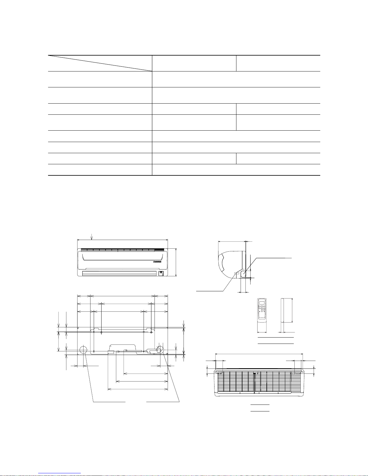
(2) Range of usage & limitations
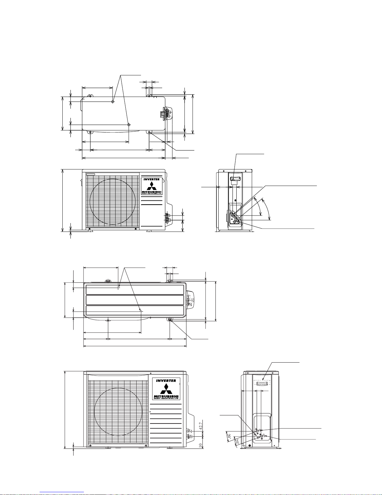
(3) Exterior dimensions
(a) Indoor unit
Models SRK20ZD-S1, 25ZD-S1, 35ZD-S1, 50ZD-S1
Indoor return air temperature
(Upper, lower limits)
Refrigerant line (one way) length Max. 15m
SRK20ZD-S1, 25ZD-S1, 35ZD-S1 SRK50ZD-S1
Cooling operation : Approximately 21 to 32˚C
Heating operation : Approximately 15 to 30˚C
Cooling operation : Approximately 21 to 43˚C
Heating operation : Approximately
-
5 to 21˚C
Power source voltage Rating ± 10%
Voltage at starting Min. 85% of rating
Frequency of ON-OFF cycle
Max. 7 times/h
(Inching prevention 5 minutes)
Max. 4 times/h
(Inching prevention 10 minutes)
ON and OFF interval Max. 3 minutes
Outdoor air temperature
(Upper, lower limits)
Vertical height difference between
outdoor unit and indoor unit
Max. 10m (Outdoor unit is higher)
Max. 10m (Outdoor unit is lower)
Max. 25m
Max. 15m (Outdoor unit is higher)
Max. 15m (Outdoor unit is lower)
Item
Models
VIEW A
117.5
580 117.5
148.5
216.5216.5
8.2
44.5
236.1
5.7
450
450
67.5
42.7
47.2
175
44.5
216.5216.5
148.5
53.5
Piping for Gas
Drain hose 540 (ø16)
Piping for Liquid 465.1 (ø6.35)
Piping hole (ø65)
Piping hole (ø65)
( )
20,25,35: ø9.52
50:
ø
12.7
397.1
45
14.5
60
788
5
60
45
815
A
250
Unit: mm
Piping hole right(left)
Terminal block
9
60
45
3
249
150
18
56
Remote controller
-
9
-
(b) Outdoor unit
Models SRC20ZD-S1, 25ZD-S1, 35ZD-S1
Drain holes
286.4
12
50
290
49.6
43.5
850
203.1
510 136.9
476
2-16x12
314
12
328
Terminal block
Service valve (Liquid)
ø6.35 (1/4'')
Service valve (Gas)
ø12.7 (1/2'')
Ground
terminal
124
34.6
20û
20û
42.7
100.3
15
640
14
Model SRC50ZD-S1
Unit: mm
290
540
14.4
47.4 42.6
264.5
71
404.5
510
720
17.8
Drain holes
50
12
39.7
99.9
340
312.5
13.5
14
139
2-16 x12
61.9
139.3 33.3
Flare connection ø6.35 (1/4")
Service valve (Liquid)
40
˚
40
˚
Flare connecting ø9.52 (3/8")
Service valve (Gas)
Terminal block
-
10
-
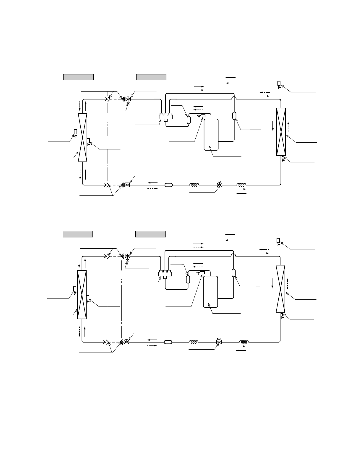
(4) Piping system
Models SRK20ZD-S1, 25ZD-S1, 35ZD-S1
Outdoor unitIndoor unit
Room temp.
sensor
Heat
exchanger
Flare connection
Heat
exchanger
sensor
Piping
(Liquid)
ø6.35
Check joint
4 way valve
Service valve (Liquid)
Flare connetion
Discharge pipe
temp. sensor
Cooling cycle
Heating cycle
Outdoor air
temp. sensor
Heat
exchanger
Heat exchanger
sensor
Compressor
Capillary tube
Strainer
Accumulator
Service valve
(Gas)
Electronic
expansion valve
Piping
(Gas)
ø9.52
Model SRK50ZD-S1
Outdoor unitIndoor unit
Room temp.
sensor
Heat
exchanger
Flare connection
Heat
exchanger
sensor
Piping
(Liquid)
ø6.35
Check joint
4 way valve
Service valve (Liquid)
Flare connection
Discharge pipe
temp. sensor
Cooling cycle
Heating cycle
Outdoor air
temp. sensor
Heat
exchanger
Heat exchanger
sensor
Compressor
Capillary tube
Strainer
Strainer
Service valve
(Gas)
Capillary tube
Electronic
expansion valve
Piping
(Gas)
ø12.7
Muffler
Capillary tube
Muffler
-
11
-
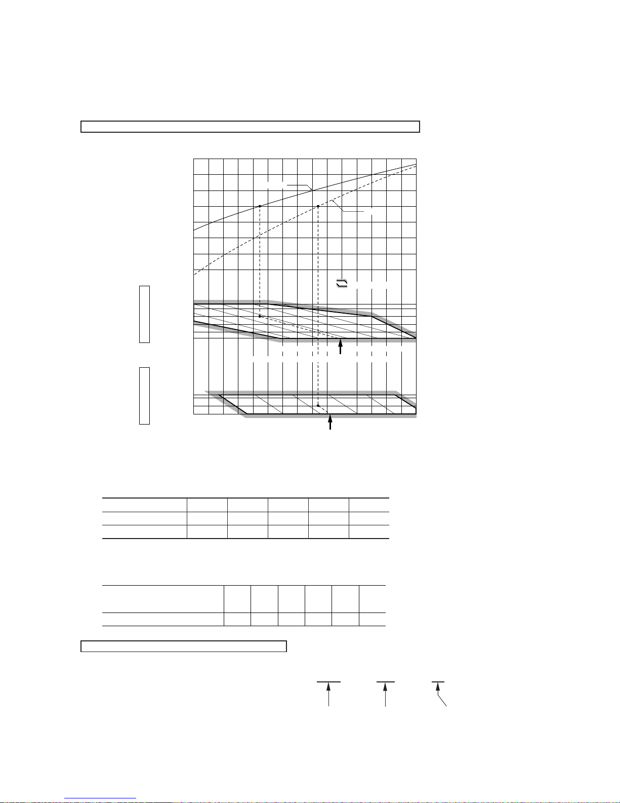
(5) Selection chart
Correct the cooling and heating capacity in accordance with the conditions as follows. The net cooling and heating capacity can be
obtained in the following way.
Net capacity = Capacity shown on specification ✕ Correction factors as follows.
(a) Coefficient of cooling and heating capacity in relation to temperatures
(b) Correction of cooling and heating capacity in relation to one way length of refrigerant piping
It is necessary to correct the cooling and heating capacity in relation to the one way piping length between the indoor and outdoor
units.
(c) Correction relative to frosting on outdoor heat exchanger during heating
In additions to the foregoing corrections (a), (b) the heating capacity needs to be adjusted also with respect to the frosting on the
outdoor heat exchanger.
How to obtain the cooling and heating capacity
Example : The net cooling capacity of the model SRK20ZD-S1 with the piping length of 15m, indoor wet-bulb temperature at 19.0˚C
and outdoor dry-bulb temperature 35˚C is Net cooling capacity = 2000 ✕ 0.975 ✕ 1.0 = 1950 W
Length 15m
Factor by air
temperatures
15
ISO-T1 Standard ConditionOutdoor air W.B. temperature ˚C W.B.
1005-5
16 18 20 22 24
20
ISO-T1 Standard ConditionIndoor air W.B. temperature ˚C W.B.
Heating
Applicable range
27
25
20
15
21
25
30
35
40
0.6
0.7
0.8
0.9
1.0
1.1
1.2
1.3
43
Cooling
Heating operation
Indoor air D.B.
temperature
˚C D.B.
Cooling operation
Outdoor air D.B.
temperature
˚C D.B.
Coefficient of cooling &
Heating capacity in
relation to temperature
Piping length [m]
Cooling
Heating
7
1.0
1.0
10
0.99
1.0
15
0.975
1.0
20
0.965
1.0
25
0.95
1.0
Air inlet temperature of
outdoor unit in ˚C WB
Adjustment coefficient
-5
0.91-30.88-10.8610.8730.9251.00
SRK20ZD-S1
-
12
-
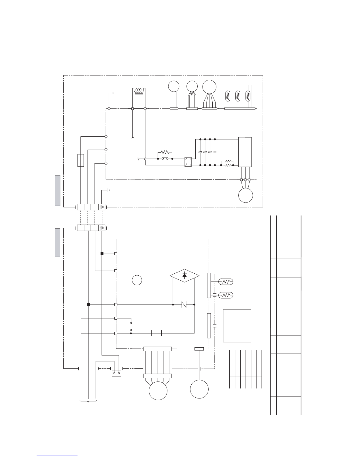
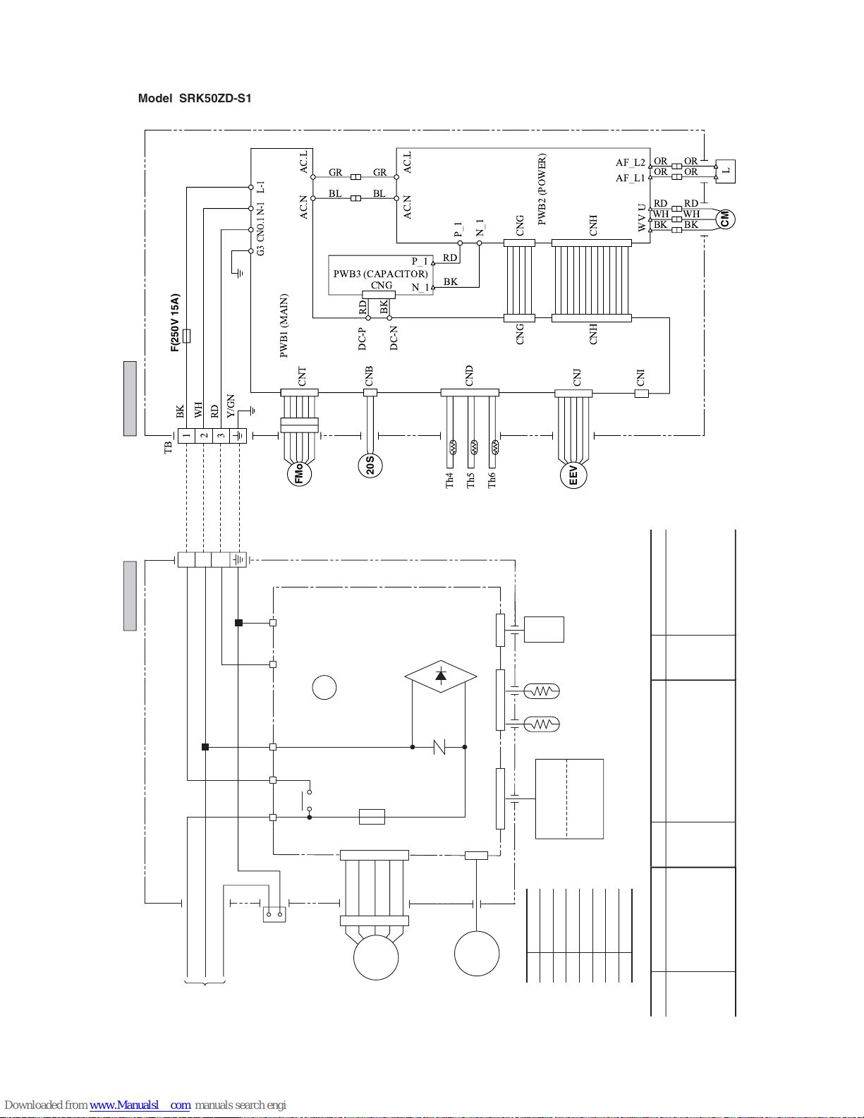
1.1.3 ELECTRICAL DATA
(1) Electrical wiring
Models SRK20ZD-S1, 25ZD-S1, 35ZD-S1
Power source
1 Phase
220/230/240V 50Hz
Outdoor unit
Indoor unit
HEAT
EXCHANGER
Printed circuit
board
Printed circuit board
BR
BL
Y/GN
BK
WH
RD
RD
1
3
4
5
6
CNU
BK
WH
Y
BL
TB TB
F2 (250V 20A)
F1
250V
3.15A
BK
WH
RD
U
V
W
BK
C2 S.IN R.IN
Re
G
WH
RD
Y/GN
N
ZNR
CNM
CNE CNG
52C3
52C
52C4
J
Th4
Th1 Th2
Th5
Th6
CNB
CNE
CNA
CND
1
2
3
NP
Power
transistor
20S
52C
EEV
FMo
DS
CM
1
2
3
( )
FM
I
SM
Display
Wireless
R-Amp
Black
Brown
Red
Blue
White
Yellow/Green
BK
BR
RD
BL
WH
Y/GN
Color symbol
Meaning of marks
Symbol
Parts name
CM
Compressor motor
F
Fuse
FM
I
F
Fan motor (Indoor)
FMo
F
an motor (Outdoor)
SM
RE
Flap motor
Reactor
Symbol
Parts name
Th
1
Room temp. sensor
Th
2
Heat exchanger
sensor
(Indoor unit)
Th
4
Heat exchanger
sensor
(Outdoor unit)
Th
5
Outdoor air temp. sensor
Th
ZNR
6
Dischar
Varistor
ge pipe temp. sensor
Symbol
Parts name
20S
4 way valve (coil)
52C
Magnetic contactor
DS
Diode stack
EEV
Electronic expansion valve
-
13
-
Power source
1 Phase
220/230/240V 50Hz
Outdoor unit
Indoor unit
HEAT
EXCHANGER
Printed circuit board
BRBLY/GN
BK
WH
RD
RD
BK
WH
Y
BL
TB
F1
250V
3.15A
N
ZNR
CNM
CNE CNG CNF
52C3
52C
52C4
J
52C
1
2
3
( )
FM
I
SM
Display
Wireless
R-Amp
Th1 Th2
Th3
13456
CNU
Black
Brown
Red
Blue
White
Yellow/Green
BKBRRD
BL
Orange
OR
Green
GR
WH
Y/GN
Color symbol
Meaning of marks
Symbol
Parts name
CFo
Capacitor for FMo
CM
Compressor motor
F
Fuse
FM
I
F
Fan motor (Indoor)
FMo
F
an motor (Outdoor)
SM
RL
L
Flap motor
Inspection lamp
Inductor
Symbol
Parts name
Th
1
Room temp. sensor
Th
2
Heat exchanger sensor (Indoor unit)
Th
3
Humidity sensor
Th
4
Heat exchanger sensor (Outdoor unit)
Th
5
Outdoor air temp. sensor
Th
6
Discharge pipe temp. sensor
Symbol
Parts name
ZNR
Varistor
20S
4 way valve (coil)
52C
Magnetic contactor
DS
Diode stack
EEV
Electronic expansion valve
EEV
FMo
20S
F(250V 15A)
CM
!
"#
Model SRK50ZD-S1
-
14
-
LO
MED
HI
AUTO
HI POWER
ECONO
ON OFF
AM PM
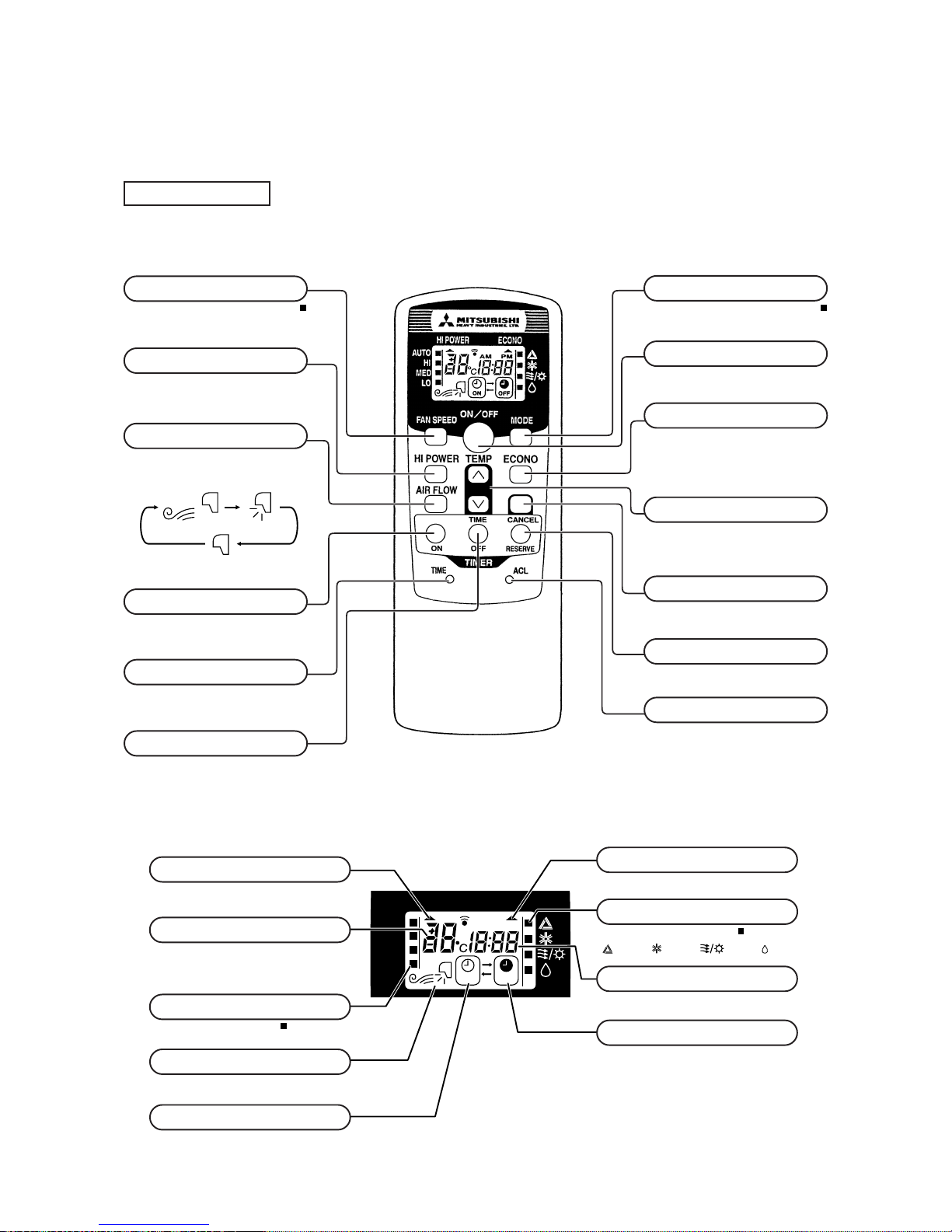
FAN SPEED button
Each time the button is pushed, the
indicator is switched over in turn.
• The above illustration shows all controls, but in practice
only the relevant parts are shown.
OPERATION MODE select button
Each time the button is pushed, the
indicator is switched over in turn.
AIR FLOW button
This button changes the flap mode. When
pressed, this button changes the mode in the
following order:
ON/OFF button
Press for starting operation, press again for
stopping.
HI POWER button
This button changes the HI POWER mode.
ECONOMY button
This button changes the ECONOMY mode.
RESET switch
Switch for resetting microcomputer.
ON TIMER button
This button selects ON TIMER operation.
TIME switch
This switch for setting the time.
OFF TIMER button
This button selects OFF TIMER operation.
TEMPERATURE button
This button sets the room temperature.
(This button changes the present time and
TIMER time.)
CANCEL button
This button cancels the ON timer and OFF
timer.
RESERVE button
This button sets the present time and
TIMER time.
S Indication section
OPERATION MODE indicator
Indicates selected operation with lamp.
[
(Auto) • (Cool) • (Heat) • (Dry)]
TEMPERATURE indicator
Indicates set temperature.
(Does not indicate temperature when operation
mode is on AUTO)
FAN SPEED indicator
Indicates set air flow rate with lamp.
AIR FLOW indicator
Shows selected flap mode.
HI POWER MODE indicator
Indicates during Hi power mode operation.
ECONOMY MODE indicator
Indicates during economy mode operation.
ON TIMER indicator
Indicates during ON TIMER operation.
TIME indicator
Indicates present time or timer setting time.
OFF TIMER indicator
Indicates OFF TIMER operation.
Models All models
Remote controller
S Operation section
1.1.4
OUTLINE OF OPERATION CONTROL BY MICROCOMPUTER
(1) Operation control function by remote control switch
(Air scroll) (Swing)
(Flap stopped)
-
15
-
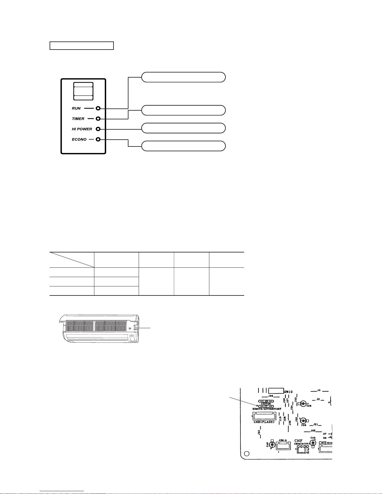
Unit indication section
Models SRK20ZD-S1, 25ZD-S1, 35ZD-S1, 50ZD-S1
(2) Unit ON/OFF button
When the remote controller batteries become weak, or if the remote controller is lost or malfunctioning, this button may be used to turn
the unit on and off.
(a) Operation
Push the button once to place the unit in the automatic mode. Push it once more to turn the unit off.
(b) Details of operation
The unit will go into the automatic mode in which it automatically determines, from room temperature (as detected by sensor),
whether to go into the cooling, thermal dry or heating modes.
Function
Room temperature
Operation mode
setting
Fan speed Flap Timer switch
Cooling About 25ºC
Thermal dry About 25ºC Auto Auto Continuous
Heating About 26ºC
Unit ON/OFF button
ECONOMY light (orange)
Illuminates during ECONOMY operation.
TIMER light (yellow)
Illuminates during TIMER operation.
HI POWER light (green)
Illuminates during HI POWER operation.
RUN (HOT KEEP) light (green)
• Illuminates during operation.
• Flashes at air flow stop due to the ‘HOT KEEP’.
(3) Power blackout auto restart function
(a) Power blackout auto restart function is a function that records the operational status of the air-conditioner immediately prior to it
being switched off by a power cut, and then automatically resumes operations at that point after the power has been restored.
(b) The following settings will be cancelled:
(i) Timer settings
(ii) High-power operations
Notes (1) The power blackout auto restart function is set at on when the air-conditioner is shipped from the
factory. Consult with your dealer if this function needs to be switched off.
(2) When power failure ocurrs, the timer setting is cancelled. Once power is resumed, reset the timer.
(3)
If the jumper wire (J7) “REMOTE/AUTORESTART” is cut, auto restart is disabled. (See the diagram
at right)
Models SRK20ZD-S1, 25ZD-S1, 35ZD-S1, 50ZD-S1
Jumper wire (J7)
-
16
-
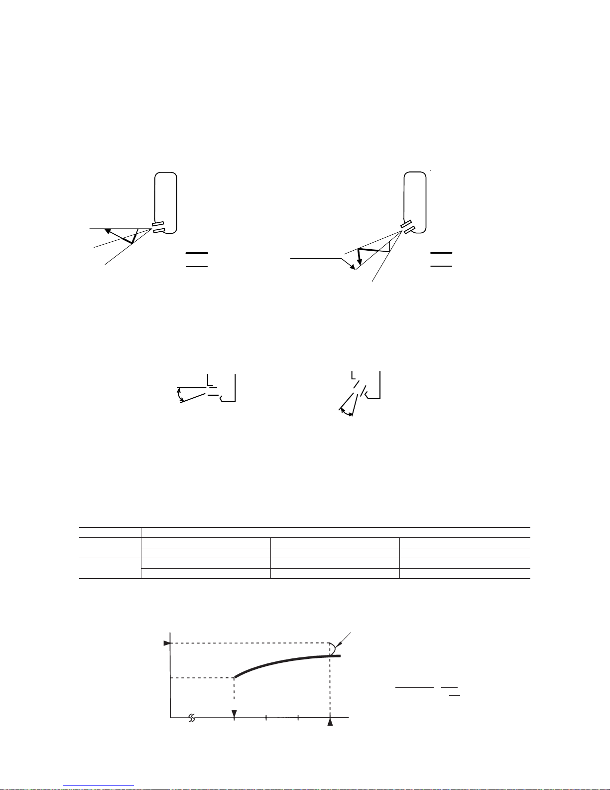
(4) Flap control
Control the flap by AIRFLOW button on the wireless remote control.
(a) Air scroll (AUTO)
The flap will be automatically set to the angle of air flow best to operation.
(i) Starting time of operation
(c) Swing flap
Flap moves in upward and downward directions continuously.
(ii) When not operating
The flap returns to the position of air flow directly below, when operation has stopped.
(b) Memory flap
While the flap is operating if the AIRFLOW button is pushed once, it stops swinging at an angle.
As this angle is memorized in the microcomputer, the flap will be automatically set to the angle when next operation is started.
¡ Recommendable stopping angle of the flap
Corrects the starting time of next operation by
calculating the temperature difference.
(Example) Heating
Setting temperature
Room temperature
Operation starting time
Time
Setting time
15 min. 10 min. 5 min.
earlier earlier earlier
¡ If the difference (= Setting temperature – Room tempera-
ture) is 4ºC, the correction value is found to be +5 minutes from the table shown above so that the starting time
of next operation is determined as follows:
15 min. earlier + 5 min. = 20 min. earlier
↑↑
Current operation Correction value
start time
s
During cooling and
t
dry operation
Thick line : Rapid movement
Thin line : Slow movement
Stops for approximately
5 seconds in the
horizontal position.
s
During heating
t
operation
Stops for approximately
5 seconds in this
position.
Thick line : Rapid movement
Thin line : Slow movement
Horizontal
blowing
COOL•DRY
Slant forward
blowing
HEAT
(5) Comfortable timer setting
If the timer is set at ON when the operation select switch is set at the cooling or heating, or the cooling or heating in auto mode operation
is selected, the comfortable timer starts and determines the starting time of next operation based on the initial value of 15 minutes and the
relationship between the room temperature at the setting time (temperature of room temperature sensor) and the setting temperature.
(Max. 60 minutes)
Operation mode Operation start time correction value (Min.)
3 < Room temp. – Setting temp. 1 < Room temp. – Setting temp.
=
<
3 Room temp. – Setting temp.
=
<
1
At cooling
+5 No change –5
3 < Setting temp. – Room temp. 2 < Setting temp. – Room temp.
=
<
3 Setting temp. – Room temp.
=
<
2
At heating
+5 No change –5
Notes (1) At 5 minutes before the timer ON time, operation starts regardless of the temperature of the room temperature sensor (Th1).
(2) This function does not operate when in the Dry or Auto Dry mode.
However, the operation in item (1) does operate in the Auto Dry mode.
(3) During the comfortable timer operation, both the RUN light and TIMER light illuminate and the TIMER light goes off after expiration of the timer, ON setting
time.
-
17
-
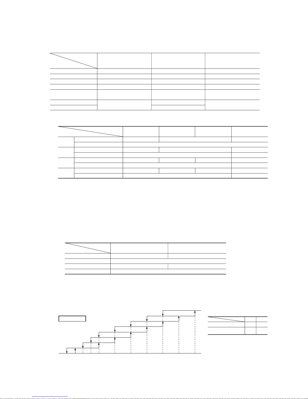
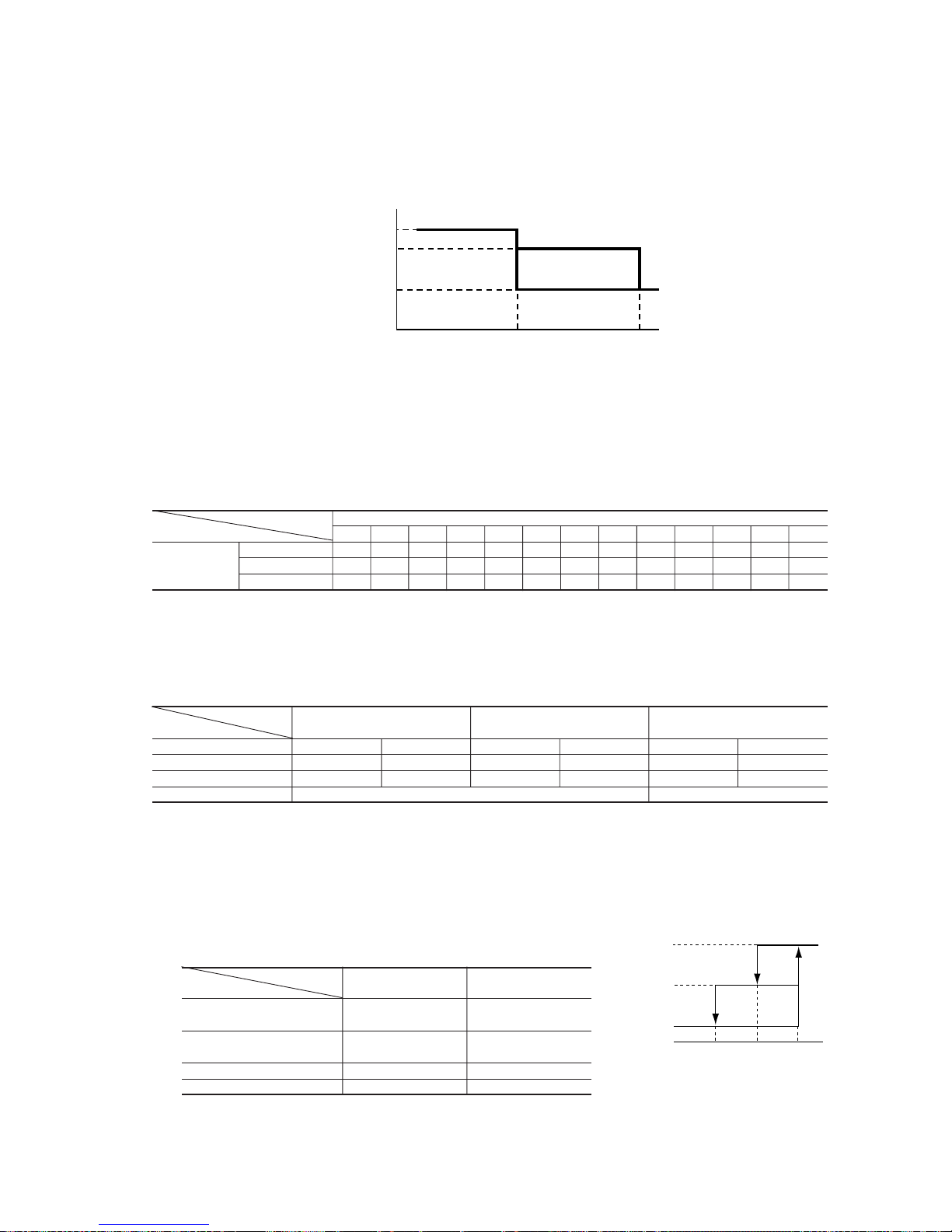
(iii) Hot keep operation
If the hot keep operation is selected during the heating operation, the indoor blower is controlled based on the temperature of
the indoor unit heat exchanger (detected with Th2, indoor unit heat exchanger sensor) to prevent blowing of cool wind.
Note (1) Refer to the table shown above right for the values A and B.
¡ Normal mode (Normal heating operation, operation after HI POWER completion)
Indoor heat exchanger temp. (˚C)
¡ Values of A, B
AB
At 0 rps command 22 25
Other than 0 rps
17 19
command
AB
20~35: 23°C
50: 20°C
28 29.5 31.5 34 36 37.5 39 40
1st speed
3rd speed
4th speed
5th speed
6th speed
7th speed
OFF
Indoor fan
(c) Details of control at each operation mode (pattern)
(i) Fuzzy operation
Deviation between the room temperature setting correction temperature and the suction air temperature is calculated in
accordance with the fuzzy rule, and used for control of the air capacity and the inverter speed.
(ii) Heating thermostat operation
¡ Operating conditions
If the speed obtained with the fuzzy calculation drops below -24 rps during the heating fuzzy operation, the operation
changes to the heating thermostat operation.
¡ Detail of operation
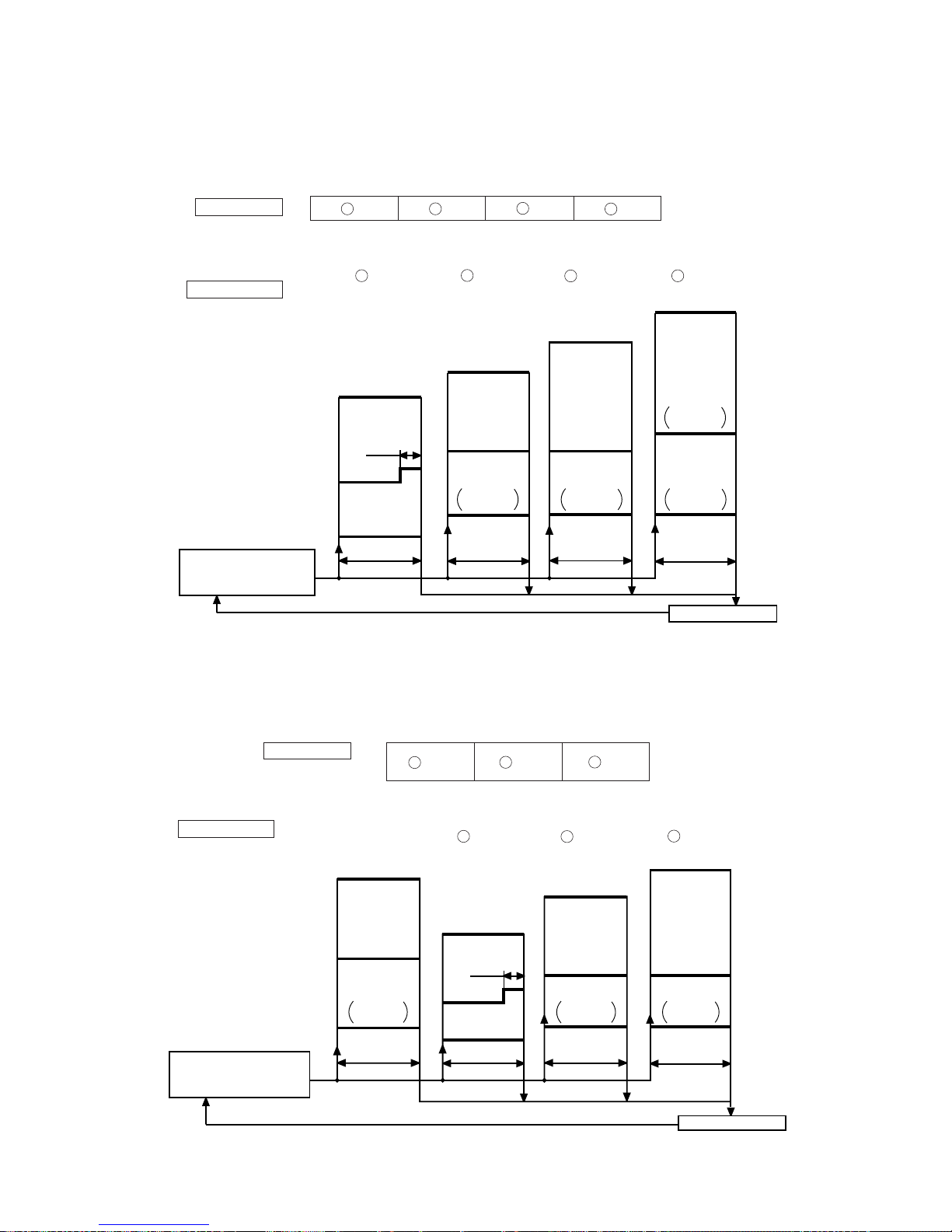
(6) Outline of heating operation
(a) Operation of major functional components in heating mode
(b) Air flow selection
(i) Speed of inverter changes within the range of selected air flow.
(ii) When the defrosting, protection device, etc. is actuated, operation is performed in the corresponding mode.
(iii) Outdoor unit blower operates in accordance with the inverter command speed.
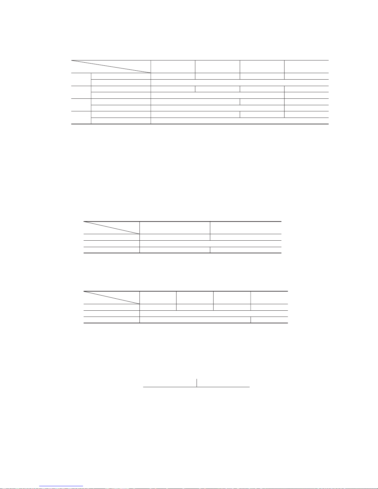
Model
SRK20, 25, 35ZD-S1 SRK50ZD-S1
Item
Inverter speed 0rps [Comp. stopped] 10 rps [10sec.] → 0rps [Comp. stopped]
Indoor fan Hot keep normal mode → 1st speed
Outdoor fan Stop 2nd speed [1min.] → stop
Flap Horizontal
Auto
HI
MED
LO
Item
Indoor fan motor ON ON OFF
Flaps ON or OFF ON or OFF Stop position control
Display Lights up Lights up Lights up or flashes
52C ON ON OFF after stop mode
Outdoor fan motor
OFF (20, 25, 35 type)
ON
OFF (20, 25, 35 type)
Depending on the stop mode (50 type) Depending on the stop mode (50 type)
4-way valve
Depending on the stop mode
ON
Depending on the stop mode
Electronic expansion valve Depending on the EEV control
When the inverter
speed is 0rps
When the inverter speed
is other than 0rps
When the inverter speed is 0rps
due to an anomalous stop
Functional
components
(20, 25, 35 only)
8th speed
(20, 25, 35 only)
9th speed
Model
SRK20ZD-S1 SRK25ZD-S1 SRK35ZD-S1 SRK50ZD-S1
Air flow selection
Inverter command speed 30~100rps 30~102rps 15~120rps
Air flow Depends on inverter command speed.
Inverter command speed 30~100rps 30~102rps 15~120rps
Air flow 8th speed fixed 6th/7th speed
Inverter command speed 30~72rps 30~72rps 30~76rps 15~62rps
Air flow 6th speed fixed 4th/5th speed
Inverter command speed 30~42rps 30~42rps 30~46rps 15~38rps
Air flow 4th speed fixed 3rd speed fixed
-
18
-
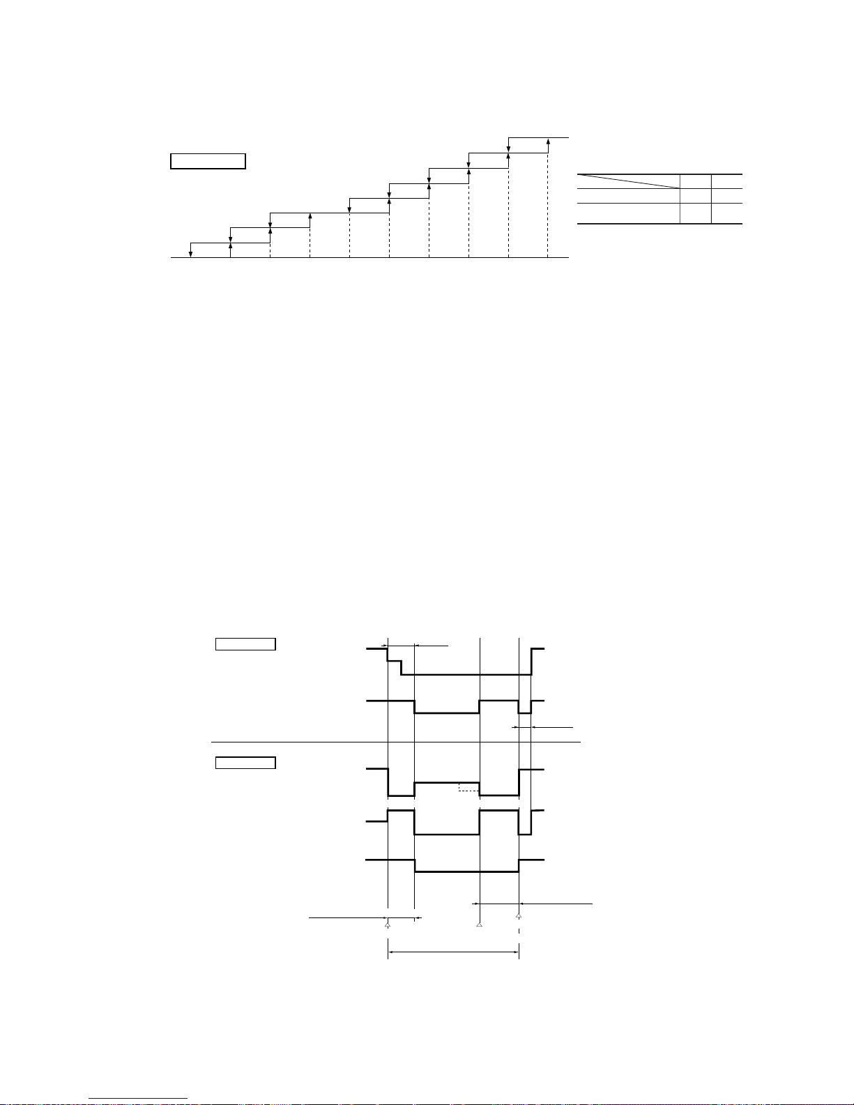
Notes (1) Refer to the table shown above right for the values A and B.
Note (2) Values in ( ) are for type 20, 25, 35.
¡ Hot keep M mode [During HI POWER operation (for 15 min.)]
Indoor heat exchanger temp. (˚C)
AB2931 32 34 36 43
(40)
(43) (47)
1st speed
3rd speed
4th speed
5th speed
6th speed
7th speed
OFF
Indoor fan
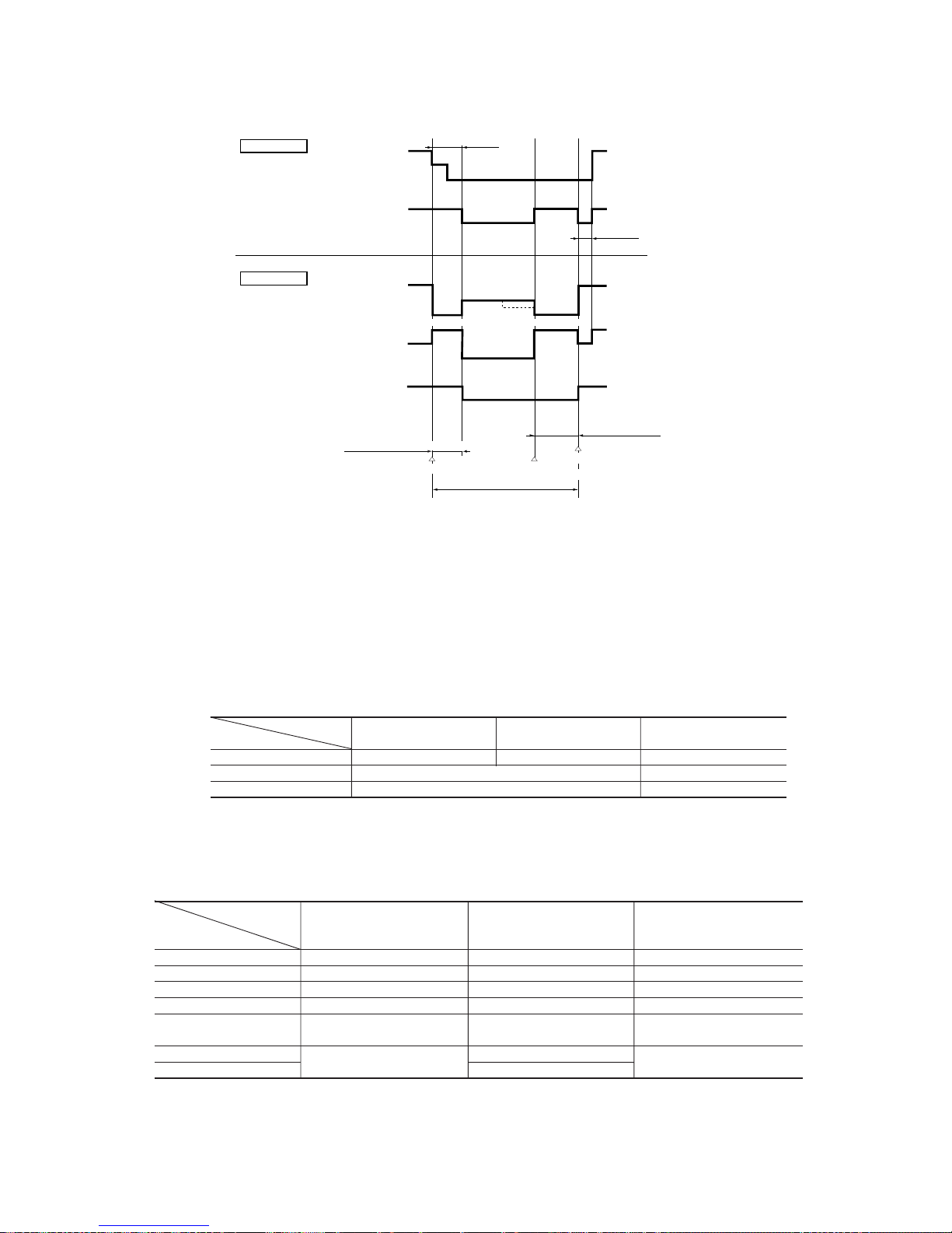
(iv) Defrosting operation
1) Starting conditions (Defrosting operation can be started only when all of the following conditions are met.)
1 After start of heating operation → When it elapsed 35 minutes. (Accumulated operation time)
2 After end of defrosting operation → When it elapsed 35 minutes. (Accumulated compressor operation time)
3 Outdoor unit heat exchanger sensor (Th4) temperature → When the temperature has been below –5ºC for 3 minutes
continuously.
4 When the temperature difference between the outdoor air sensor temperature and the outdoor unit heat exchanger
sensor temperature exceeded 20. 25 type: 7.0°C, 35 type: 5.0°C, 50 type: 4.0°C
5 During continuous compressor operation
In addition, when the speed command from the indoor controller of the indoor unit during heating operation has
counted 0 rps 10 times or more and all conditions of 1, 2 and 3 above are satisfied (note that when the temperature
for Th4 is -5°C or less: 62 rps or more, -4°C or less: less than 62 rps), defrost operation is started.
2) Operation of functional components during defrosting operation
¡ 20, 25, 35 type
Indoor fan
RUN light
Corresponding
to speed
OFF
ON
Flashing
(Hot keep)
Outdoor fan
Inverter
command
Fuzzy calculated
value
70 rps
0
Corresponding
to speed
OFF
OFF
ON
(1)
4-way valve
Final defrost operation
Defrost control
Hot keep
Indoor unit
Outdoor unit
60 sec.
Hot keep
50 sec.
Normal heating operation restored
Defrost end
(Th4
>
=
13˚C, 10 minutes)
Defrost operation
Defrost operation
preparation
6th speed 6th speed
¡ Values of A, B
AB
At 0 rps command 22 25
Other than 0 rps
17 19
command
8th speed
9th speed
(20, 25, 35 only)
(20, 25, 35 only)
Note (1) When outdoor unit heat exchanger sensor (Th4) temperature becomes 2°C or higher, inverter command changes 70 rps to 50
rps.
-
19
-
(v) Heating “HI POWER” operation (HI POWER button on remote controller: ON)
Operation is maintained for 15 minutes with a higher blow out air temperature.
¡ Detail of operation
Model
SRK20ZD-S1 SRK25, 35ZD-S1 SRK50ZD-S1
Item
Inverter speed 100 rps 102 rps 120 rps
Indoor fan Hot keep M mode (max 8th speed) Hot keep M mode (max 7th speed)
Outdoor fan 4th speed 2nd speed
Notes (1) Room temperature is not adjusted during the HI POWER operation.
(2) Protective functions will actuate with priority even during the HI POWER operation.
3) Ending conditions (Operation returns to the heating cycle when either one of the following is met.)
1 Outdoor heat exchanger sensor (Th4) temperature: 13ºC or higher (50 type: 20°C or higher)
2 Continued operation time of defrosting → For more than 10 min.
Indoor fan
RUN light
Corresponding
to speed
OFF
ON
Flashing
(Hot keep)
Outdoor fan
Inverter
command
Fuzzy calculated
value
70 rps
(1)
0
Corresponding
to speed
OFF
OFF
ON
4-way valve
Final defrost operation
Defrost control
Hot keep
Indoor unit
Outdoor unit
75 sec.
Hot keep
60 sec.
Normal heating operation restored
Defrost end
(Th4
>
=
20°C, 10 minutes)
Defrost operation
Defrost operation
preparation
2nd speed 2nd speed
(7) Outline of cooling operation
(a) Operation of major functional components in Cooling mode
¡ 50 type
Item
Indoor fan motor ON ON OFF
Flaps ON or OFF ON or OFF Stop position control
Display Lights up Lights up Lights up or flashes
52C ON ON OFF after stop mode
Outdoor fan motor
OFF (20, 25, 35 type)
ON
OFF (20, 25, 35 type)
Depending on the stop mode (50 type) Depending on the stop mode (50 type)
4-way valve
Depending on the stop mode
ON
Depending on the stop mode
Electronic expansion valve Depending on the EEV control
When the inverter
speed is 0rps
When the inverter speed
is other than 0rps
When the inverter speed is 0rps
due to an anomalous stop
Functional
components
Note (1) When outdoor unit heat exchanger sensor (Th4) temperature becomes 7°C or higher, inverter instruction changes 70 rps to 50
rps.
-
20
-
(c) Detail of control in each mode (Pattern)
(i) Fuzzy operation
During the fuzzy operation, the air flow and the inverter speed are controlled by calculating the difference between the room
temperature setting correction temperature and the suction air temperature.
(ii) Cooling thermostat operation
1) Operating conditions
During the cooling fuzzy operation or when the speed obtained by the fuzzy calculation is less than -24 rps.
2) Detail of operation
(b) Air flow selection
(i) Speed of inverter changes within the range of selected air flow.
(ii) When any protective function actuates, the operation is performed in the mode corresponding to the function.
(iii) Outdoor blower is operated in accordance with the inverter command speed.
(iii) Cooling “HI POWER” operation (HI POWER button on remote controller: ON)
The unit is operated continuously for 15 minutes regardless of the setting temperature.
1) Detail of operation
Model
SRK20, 25, 35ZD-S1 SRK50ZD-S1
Item
Inverter speed 0 rps [Comp. stopped] 10rps [10sec.] → 0rps [Comp. stopped]
Indoor fan Corresponds to fan speed switch.
Outdoor fan Stop 2nd speed [1min.] → stop
Notes (1) Protective functions will actuate with priority even during the “HI POWER” operation.
(2) Room temperature is not adjusted during the “HI POWER” operation
(8) Outline of dehumidifying operation
(a) After operating the indoor blower for 20 seconds from immediately after the start of operation, the indoor temperature is checked
and, based on the result of check, the cooling oriented dehumidifying or heating oriented dehumidifying is selected.
Heating oriented dehumidifying Cooling oriented dehumidifying
Low –3 High
Room temperature - Setting temperature (deg)
Cooling or heating oriented dehumidifying is selected again one hour after the first selection of the cooling or heating oriented
dehumidifying.
Auto
HI
MED
LO
Model
SRK20ZD-S1 SRK25ZD-S1 SRK35ZD-S1 SRK50ZD-S1
Air flow selection
Inverter command speed 20~60rps 20~70rps 20~98rps 15~90rps
Air flow Depends on inverter command speed.
Inverter command speed 20~60rps 20~70rps 20~98rps 15~90rps
Air flow 7th speed fixed 5th~7th speed
Inverter command speed 20~52rps 20~58rps 15~60rps
Air flow 5th speed fixed 3rd~5th speed
Inverter command speed 20~34rps 20~38rps 15~30rps
Air flow 2nd speed fixed
Model
SRK20ZD-S1 SRK25ZD-S1 SRK35ZD-S1 SRK50ZD-S1
Item
Inverter speed 60 70 98 90
Indoor fan 7th speed
Outdoor fan 4th speed 2nd speed
-
21
-
D range C range B range A range
(ii) Heating oriented dehumidifying
After interrupting the compressor operation for 3 minutes (by the 3-minute timer) following the determination of heating
oriented dehumidifying, the unit begins in the heating operation. If the room temperature exceeds the setting temperature by
2ºC or more, the unit checks the room temperature at 5-minute intervals and, depending on the result, determines the range
of heating oriented dehumidifying operation.
Operation range
DCBA
Low –1 0 +2 High
Room temperature – Setting temperature (deg)
(D) (C) (C) (B)
OFF
3rd speed
25 sec.
OFF
0
20, 25, 35 type : 38
50 type : 24
20, 25, 35 type : 50
50 type : 40
50 type :
4th speed
20, 25, 35 type : 30
50 type : 15
5th speed
2nd speed
1st speed
50 type :
1st speed
50 type :
1st speed
50 type :
1st speed
Inverter speed
Indoor fan
Outdoor fan
Determination of cooling
oriented dehumidifying
operation range
Temperature check
5 min. 5 min. 5 min. 5 min.
Operation pattern
OLM
Low –1 0 High
Room temperature – Setting temperature (deg)
Operation range
Heating operation O range L range M range
4th speed
OFF
3rd speed
OFF
4th speed
2nd speed
1st speed
20, 25, 35 type : 38
50 type : 28
20, 25, 35 type : 30
50 type : 15
20, 25, 35 type : 48
50 type : 44
0
50 type :
1st speed
50 type :
1st speed
25 sec.
50 type :
1st speed
Inverter speed
Indoor fan
Outdoor fan
Determination of heating
oriented dehumidifying
operation range
Temperature check
5 min. 5 min. 5 min.
Depends on
the operation
condition
Operation pattern
Note (1) Figures in the parentheses
( ) show the values at
economical operation.
Note (1) Figures in the parentheses
( ) show the values at
economical operation.
(b) Outline of control
(i) Cooling oriented dehumidifying
Room temperature is checked at 5-minute intervals after selecting the cooling or heating oriented dehumidifying in order to
determine the operation range.
(O) (L) (L)
-
22
-
(9) Outline of automatic operation
(a) Determination of operation mode
The unit checks the room temperature and the outdoor air temperature after operating the indoor and outdoor blowers for 20
seconds, determines the operation mode and the room temperature setting correction value, and then begins in the automatic
operation.
Heating
Dehumidifying
Cooling
Room temperature (˚C)
Outdoor temperature (˚C)
27.5
25.5
19.5
18
30
(b) The unit checks the temperature every hour after the start of operation and, if the result of check is not same as the previous
operation mode, changes the operation mode.
(c) When the unit is started again within one hour after the stop of automatic operation or when the automatic operation is selected
during heating, cooling or dehumidifying operation, the unit is operated in the previous operation mode.
(d) Setting temperature can be adjusted within the following range. There is the relationship as shown below between the signals of
the wireless remote controller and the setting temperature.
Signals of wireless remote controller (Display)
–6 –5 –4 –3 –2 –1 ±0+1+2+3+4+5+6
Setting
Cooling 19 20 21 22 23 24 25 26 27 28 29 30 31
temperature
Dehumidifying 19 20 21 22 23 24 25 26 27 28 29 30 31
Heating 20 21 22 23 24 25 26 27 28 29 30 31 32
(10) Economical operation
(ECONO button on remote controller: ON)
(a) The set temperature is raised by 1.5ºC (0.5ºC every one hour) at cooling operation and lowered by 2.5ºC (Steps of 1ºC, 1ºC and
0.5ºC every one hour) at heating operation to continue the operation with the following contents.
(b) Detail of operation
(11) Protective control function
(a) Frost prevention for indoor heat exchanger (During cooling or dehumidifying)
(i) Operating conditions
1) Indoor heat exchanger temperature (detected with Th2) is lower than 5ºC.
2) 10 minutes after reaching the inverter command speed except 0 rps.
(ii) Detail of anti-frost operation
5°C or lower 2.5°C or lower
Item
Upper limit speed
20, 25 : 44 rps
0rps
35, 50 : 70 rps
Indoor fan Depends on operation mode
20, 25, 35: Max 2nd
50: 2nd
Outdoor fan Depends on operation mode OFF
4-way valve OFF Depends on stop mode
(iii) Reset conditions: The indoor heat exchanger temperature (Th2) is 8ºC or higher after 5 minutes of operation following
control of the inverter command speed upper limit.
Model
SRK20, 25ZD-S1 SRK35ZD-S1 SRK50ZD-S1
Item
Operation mode Cooling Heating Cooling Heating Cooling Heating
Inverter command speed 20~52rps 20~72rps 20~58rps 20~76rps 15~60rps 15~62rps
Indoor fan 2nd, 5th speed 4th, 6th speed 2nd, 5th speed 4th, 6th speed 3rd~5th speed 4th, 5th speed
Outdoor fan 3rd speed 1st speed
Indoor heat exchanger
temperature
Indoor heat exchanger
temperature (°C)
2.5 5 8
0 rps
Upper
limit
speed
Inverter
command
speed
-
23
-
(b) Indoor fan motor protection
When the air conditioner is operating and the indoor fan motor is turned ON, if the indoor fan motor has operated at 300 rpm or
under for more than 30 seconds, the unit enters first in the stop mode and then stops the entire system.
TIMER light illuminates simultaneously and the RUN light flashing 6 times at each 8-second.
(c) Dew condensation prevention control [Cooling (including automatic), cooling oriented dehumidifying operation)
◆ SRK20, 25, 35ZD-S1
(i) Operating conditions: When compressor is kept ON for 30 min. after the unit starts operation.
(ii) Operation contents
(iii) Reset conditions: When compressor is off. (ex. thermo becomes OFF, operation mode is changed)
◆ SRK50ZD-S1
(i) Operating conditions: When the following conditions are met after 20 minutes or more of continuous operation after
operation starts.
1 The command speed is 28 rps or higher
2 The humidity sensor value is 68% or higher
(ii) Operation contents
(iii) Reset conditions: When either of the following conditions is satisfied.
1 The command speed is lower than 28 rps.
2 The humidity sensor value is less than 63%.
(d) Prevention of continuous low speed operation: For oil return to compressor
(i) Operating conditions: When command speed of less than 30(26) rps continues for 8(60) minutes
(ii) Detail of operation: The unit is operated at command speed of 30 rps forcibly for 15 seconds. (The indoor and outdoor
fans are not changed.)
Notes (1) When the command of exceeding 30 rps is directed during 30 rps forced operation, the unit follows it.
Note (2) Values in ( ) are for Type 50.
(e) Compressor protection start
(i) When the indoor unit calculated speed is 64 rps or over at operation start, the unit is operated with 64 rps for 1 minute and 45
seconds. (All models) After that when the calculated speed is 96 rps or over, the unit is operated with 96 rps for 5 minutes
then moved to command speed. (50 type only)
(ii) At thermo operation (OFF → ON) this control is not executed.
(iii) The indoor unit fan corresponds to the command speed of each operation mode.
Note (1) When the calculated speed is less than 64 rps, the unit is started with low load starting described in article (f).
(f) Low load starting
(i) When the unit is started with calculated speed of less than 60(30) rps, it is operated with 60(30) rps for 80(60) seconds, then
the operation is moved to the command speed.
(ii) The indoor fan corresponds to the operation mode.
Cooling: Speed corresponding to the command speed of air flow switching
Dehumidification: Speed decided in the operation region
Heating: The lower one between the speed corresponding to the command speed and the hot keep speed
Note (1) Values in ( ) are for Type 50.
Type
SRK20ZD-S1 SRK25ZD-S1 SRK35ZD-S1
Item
Upper limit speed 60 rps 62 rps 86 rps
Type
SRK50ZD-S1
Item
Fan Speed Medium Indoor fan speed 4th speed
Fan Speed Low Indoor fan speed 4th speed
Other Settings Indoor fan speed Corresponding to command speed
Humidity (%)
68 73
50 rps
30 rps
Inverter command speed at upper limit

-
24
-
(g) Inching prevention
When the compressor goes into the thermo operation within 10(5) minutes since operation start or becomes various dehumidifying
operations, the operation is continued with the command speed of 20(15) rps forcibly.
Note (1) Values in ( ) are for Type 50.
(h) Current safe
(i) Purpose: Current is controlled not to exceed the upper limit of the setting operation current.
(ii) Detail of operation: Input current to the converter is monitored with the current sensor fixed on the printed circuit board
of the outdoor unit and, if the operation current value reaches the limiting current value, the inverter speed is reduced.
If the mechanism is actuated when the speed of outdoor unit is less than 30 rps, the compressor is stopped immediately.
Operation starts again after a delay time of 3 minutes.
(i) Current cut
(i) Purpose: Inverter is protected from overcurrent.
(ii) Detail of operation: Output current from the converter is monitored with a shunt resistor and, if the current exceeds the
setting value, the compressor is stopped immediately. Operation starts again after a delay time of 3 minutes.
(j) Heating overload protective control
(i) Operating conditions : When the unit is operating with the outdoor unit speed other than 0 rps or when the outdoor air
temperature (detected by Th5) rose beyond 17ºC for 30 seconds continuously.
(ii) Detail of operation
1) Indoor fan speed is raised forcibly by 1 step.
2) Taking the upper limit of control speed range at 60 rps, if the output speed obtained with the fuzzy calculation exceeds the
upper limit, the upper limit value is maintained.
3) The outdoor fan is set on 2nd speed. (20, 25, 35 types only)
4) The lower limit of control speed is set to 40(35) rps and even if the calculated result becomes lower than that after fuzzy
calculation, the speed is kept to 40(35) rps. However, when the thermo becomes OFF, the speed is reduced to 0 prs.
(iii) Reset conditions: When the outdoor air temperature drops below 16ºC.
Note (1) Values in ( ) are for Type 50.
(k) Cooling overload protective control
(i) Operating conditions: When the outdoor unit is operating with the speed of other than 0 rps, or when the outdoor air
temperature (detected by Th5) becomes 41ºC or over for 30 seconds continuously.
(ii) Detail of operation
1) Outdoor fan is stepped up by 3(1) speed step.
2) The lower limit of control speed is set to 30 rps and even if the calculated result becomes lower than that after fuzzy
calculation, the speed is kept to 30 rps. However, when the thermo becomes OFF, the speed is reduced to 0 rps.
3) The upper limit of control speed is 72 rps.
(iii) Restoration condition: When the outdoor air temperature becomes 40ºC or less
Note (1) Values in ( ) are for Type 50.
(l) Freezing cycle system protective control
(i) Operating conditions: When both of following conditions have continued for more than 5 minutes later than 5 minutes
after the start of operation.
1) Command speed is higher than 60 rps
2) During cooling, dehumidifying: Indoor heat exchanger temperature - Room temperature > –4ºC
During heating: Indoor heat exchanger temperature - Room temperature < 6ºC
(ii) Detail of operation
The command speed repeats 30 minutes at 30rps ↔ 2 minutes at 62 rps.
(iii) Restoration conditions: When the condition becomes outside of either conditions 1) or 2) shown above
Note (1) This control is valid when the room air temperature is in the range of 10 to 40ºC at cooling and dehumidification operation and 0 to 40ºC at heating
operation.
-
25
-
Notes (1) When the discharge pipe temperature is in the range of 100(90) to 125(110)ºC, the speed is reduced by 4 rps.
(2) When the discharge pipe temperature is raised and continues operation for 20 seconds without changing, then the speed is reduced again by 4 rps.
(3) If the discharge pipe temperature is still 90 (80) ºC or greater but less than 100 (90) ºC even when the inverter command speed is maintained for 3
minutes when the temperature is 90 (80) ºC or greater but less than 100 (90) ºC, the speed is raised by 2 rps and kept at that speed for 3 minutes. This
process is repeated until the command speed is reached.
(4) Lower Limit Speed
Cooling Heating
20, 25, 35 type 20 30
50 type 22 38
(5) Values in ( ) are for Type 50.
2) If the temperature of 125 (110)ºC is detected by the sensor on the discharge pipe, then the compressor will stop immediately.
When the discharge pipe temperature drops and the time delay of 3 minutes is over, the unit starts again within 1 hour but
there is no start at the third time.
(n) Serial signal transmission error protection
(i) Purpose: Prevents malfunction resulting from error on the indoor ↔ outdoor signals.
(ii) Detail of operation: When the indoor unit controller ↔ outdoor unit controller signals cannot be received, the compressor
is stopped immediately. Once the operation stops, it does not start any more.
(TIMER light on the indoor unit flashing at the same time.)
(o) High pressure control
(i) Purpose: Prevents anomalous high pressure operation during heating.
(ii) Detector: Indoor unit heat exchanger sensor (Th2)
(iii) Detail of operation:
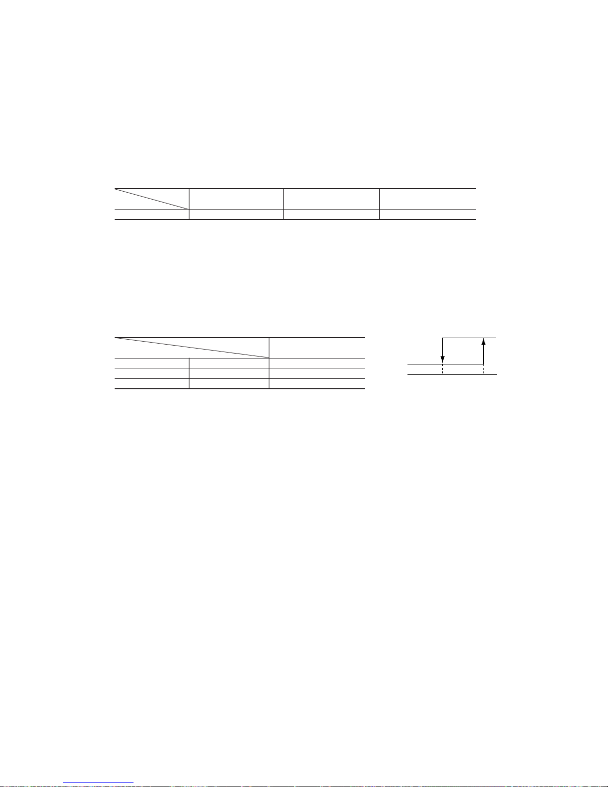
(m) Compressor overheat protection
(i) Purpose: It is designed to prevent deterioration of oil, burnout of motor coil and other trouble resulting from the compressor
overheat.
(ii) Detail of operation
1) Speeds are controlled with temperature detected by the sensor mounted on the discharge pipe.
Discharge pipe temperature (˚C)
Lower limit
(4)
After lapse of 3 min. or over
(3)
After lapse of 3 min. or over
(3)
After lapse of 3 min. or over
(3)
4 rps
4 rps
(1)
0 rps
(Example) Fuzzy
90
(80)
100
(90)
125
(110)
Notes (1) RPSmin: The lower one between the outdoor unit speed and the command speed
Note (2) Values in ( ) are for Type 50.
¡ Temperature list
ABC
RPSmin < 40(88) 48 (48.5) 53 (56) 58 (61)
40(88)
<
=
RPSmin < 50(108)
48 (44) 53 (51.5) 58 (56.5)
50(108)
<
=
RPSmin 48.5 (39) 56 (46.5) 61 (51.5)
(Example) Fuzzy
Indoor unit heat exchanger temperature (˚C)
Lower limit
speed 20(35)rps
After lapse of 20 Sec. or over
(2)
After lapse of 20 Sec. or over
(2)
After lapse of 20 Sec. or over
(2)
B
C
8 rps
(1)
8 rps
0 rps
A
Notes (1) When the indoor unit heat exchanger temperature is in the range of B~C ºC, the speed is reduced by 8 rps at each 20 seconds. When the temperature is C
ºC or over for 1 minute continuously, the inverter is stopped.
(2) When the indoor unit heat exchanger temperature is in the range of A~B ºC, if the inverter command speed is been maintained and the operation has
continued for more than 20 seconds at the same speed, it returns to the normal heating operation.
(3) Indoor blower retains the fan tap when it enters in the high pressure control. Outdoor blower is operated in accordance with the speed.
Unit : ºC
-
26
-
(p) Heating low outdoor temperature protective control (50 type only)
◆ <I>
(a) Operating conditions: When the outdoor air temperature sensor (Th5) is 4ºC or lower continues for 5 minutes while the
outdoor speed is other than 0 rps.
(b) Operation content: When the command speed is less than 22 rps, the command speed is forcibly set at 22 rps.
(c) Reset conditions: When the outdoor air temperature sensor (Th5) becomes 6ºC or higher.
◆ <II >
(a) Operating conditions: When the outdoor air temperature sensor (Th5) is 0ºC or lower continuously for 5 minutes while
the outdoor speed is other than 0 rps.
(b) Operation content: The outdoor fan motor speed is raised to the next higher speed. (Upper limit 2nd speed)
(c) Reset conditions: When the outdoor air temperature sensor (Th5) becomes 2ºC or higher.
◆ <III>
(a) Operating conditions: When the temperature sensed by the outdoor heat exchanger sensor (Th4) becomes –10ºC or
lower continuously for 1 minute.
(b) Operation content: When the command speed upper limit is set at 70 rps.
(c) Reset conditions: When the temperature sensed by the outdoor heat exchanger sensor (Th4) becomes -7ºC or higher.
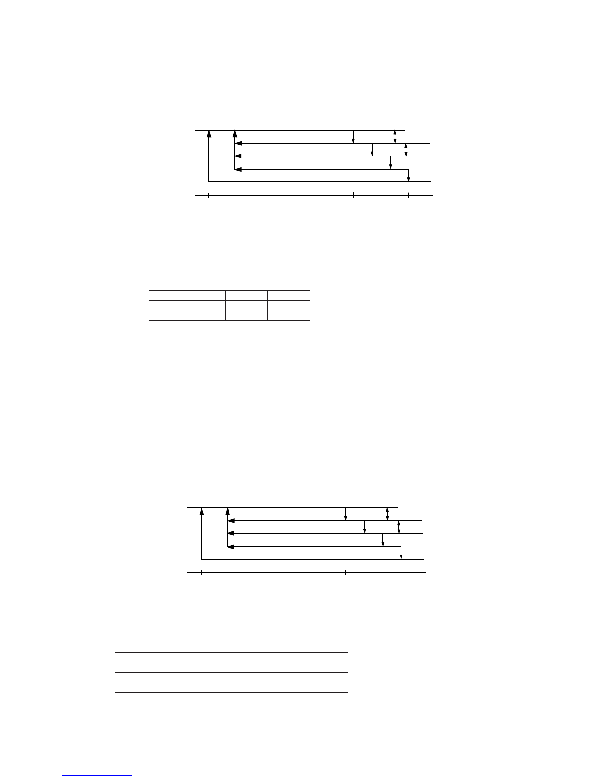
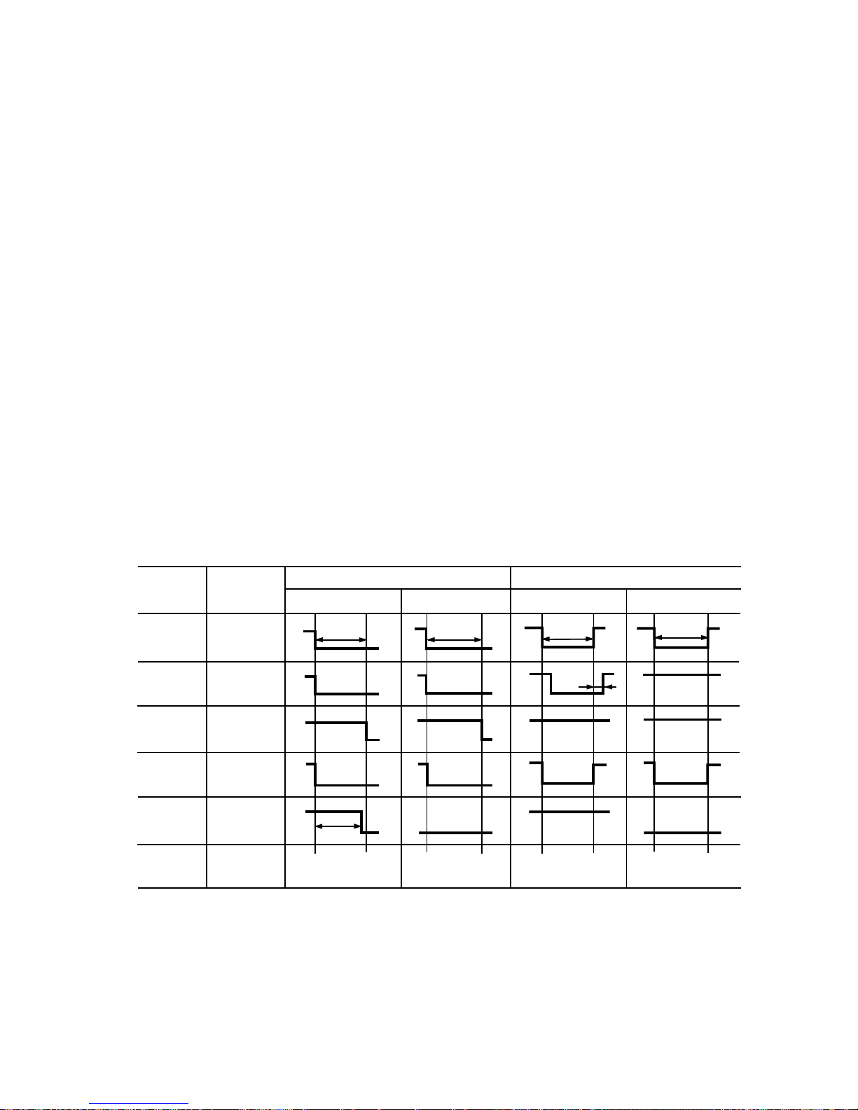
(q) Stop mode
(i) Operating conditions: When the operation mode is changed, when the dehumidifying operation is changed from the
heating oriented mode to the cooling oriented mode or vice versa, or when the inverter speed turns to 0 rps. [When 0 rps is
commanded from the indoor unit controller, or when an outdoor protective function is actuated]
(ii) Detail of operation
◆ 20, 25, 35 type
When stopped by indoor unit controller When stopped or reset by outdoor unit protective function
Function Operation
Heating, heating Cooling, cooling Heating, heating Cooling, cooling
oriented dehumidifying oriented dehumidifying oriented dehumidifying oriented dehumidifying
Stop Full stop Stop Full stop Stop Restart Stop Restart
(0 rps command) (0 rps command) (0 rps command) (0 rps command)
Inverter
speed
Indoor
fan
Indoor
power
relay
Outdoor
fan
4-way
valve
(Command
speed)
0
(Speed
dependent)
OFF
ON
OFF
3 min.
(1)
3 min.
(1)
2 min. 2 min.
55 sec. 55 sec.
Hot keep
2 min.55sec.
ON
OFF
ON
OFF
1st speed
-
27
-
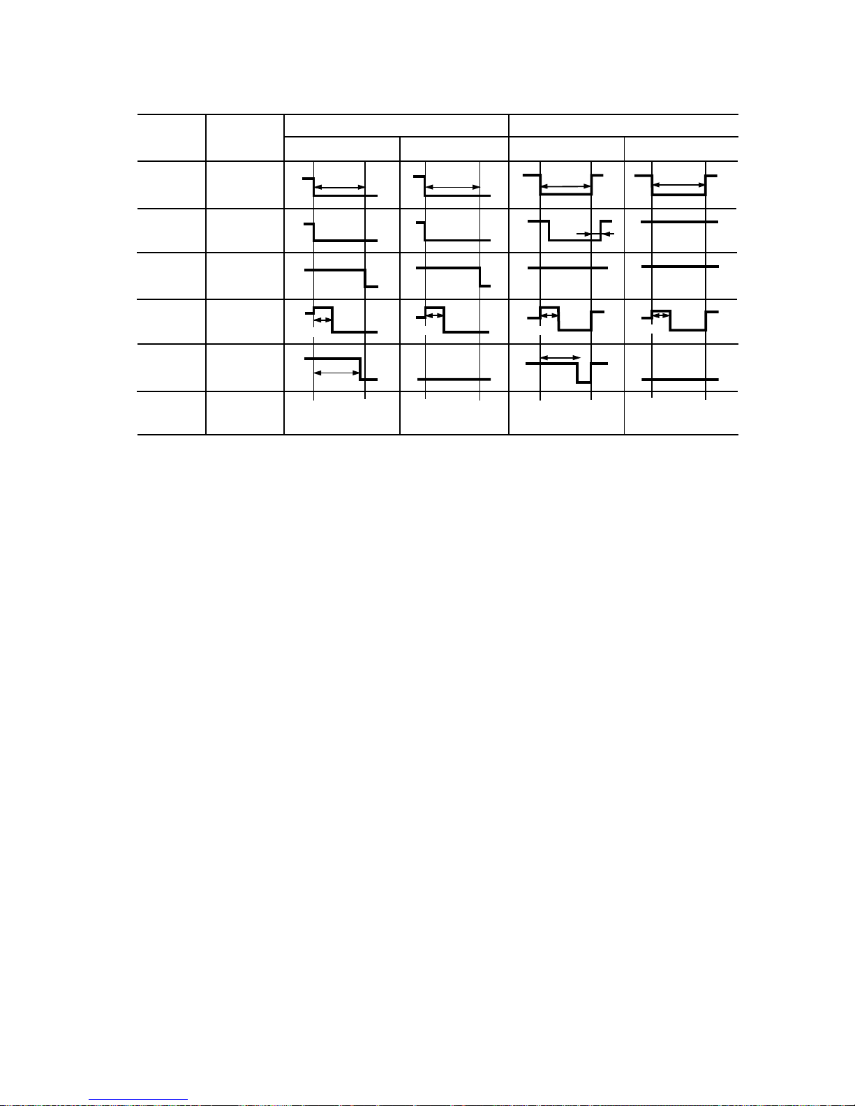
◆ 50 type
Note (1) When the start delay of compressor of indoor unit controller is actuated and the operation is reset, it takes 2 minutes and 55 seconds.
When stopped by indoor unit controller When stopped or reset by outdoor unit protective function
Function Operation
Heating, heating Cooling, cooling Heating, heating Cooling, cooling
oriented dehumidifying oriented dehumidifying oriented dehumidifying oriented dehumidifying
Stop Full stop Stop Full stop Stop Restart Stop Restart
(0 rps command) (0 rps command) (0 rps command) (0 rps command)
Inverter
speed
Indoor
fan
Indoor
power
relay
Outdoor
fan
4-way
valve
(Command
speed)
0
(Speed
dependent)
OFF
ON
OFF
3 min.
(1)
3 min.
(1)
3 min.
2 min.
55 sec.
Hot keep
2 min.55sec.
ON
OFF
ON
OFF
2nd speed 2nd speed
2nd speed
2nd speed
1 min.
1 min.
1 min.
1 min.
1st speed
2 min.55sec.
-
28
-
1.1.5 APPLICATION DATA
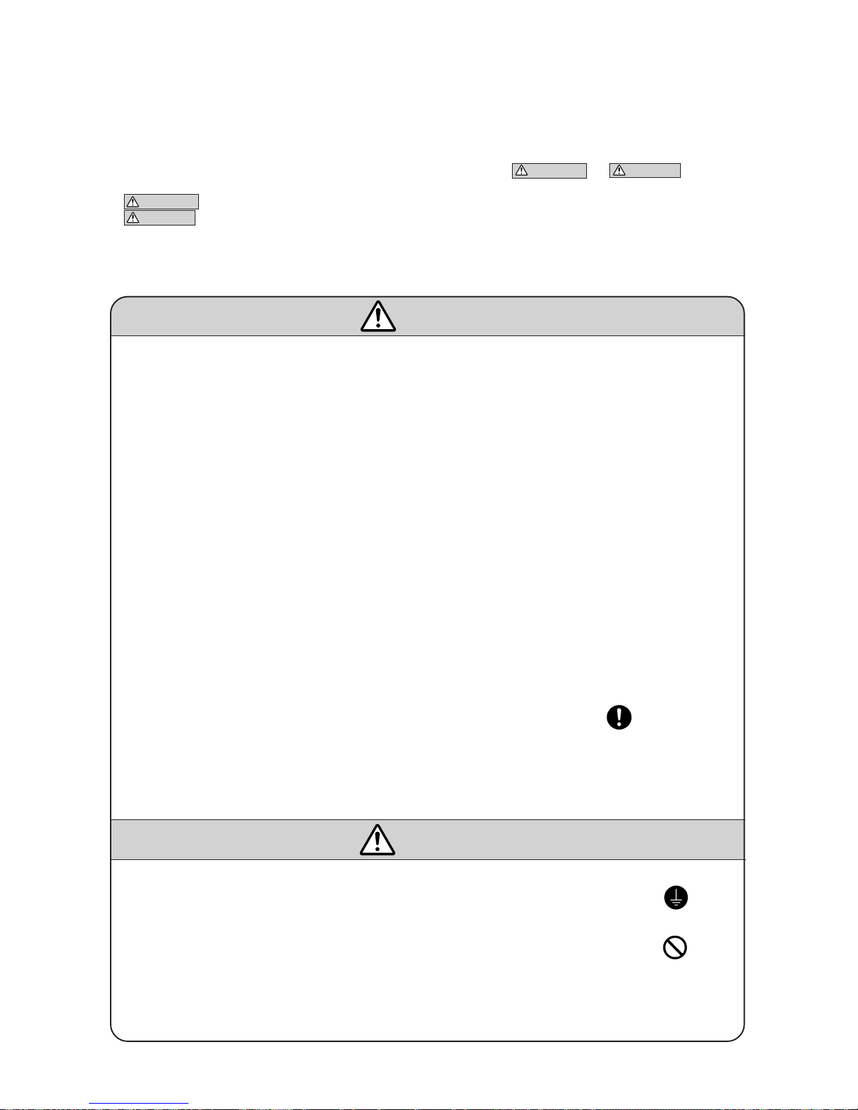
SAFETY PRECAUTIONS
¡ Please read these “Safety Precautions” first then accurately execute the installation work.
¡ Though the precautionary points indicated herein are divided under two headings,
WARNING and CAUTION , those points
which are related to the strong possibility of an installation done in error resulting in death or serious injury are listed in the
WARNING section. However, there is also a possibility of serious consequences in relationship to the points listed in the
CAUTION section as well. In either case, important safety related information is indicated, so by all means, properly observe all
that is mentioned.
¡ After completing the installation, along with confirming that no abnormalities were seen from the operation tests, please explain
operating methods as well as maintenance methods to the user (customer) of this equipment, based on the owner’s manual.
Moreover, ask the customer to keep this sheet together with the owner’s manual.
WARNING
¡ To disconnect the appliance from the mains supply this appliance must be connected to the mains by means of
a circuit breaker or a switch (use a recognized 16A) with a contact separation of at least 3mm.
¡ The appliance shall be installed in accordance with national wiring regulations.
¡ This system should be applied to places as households, residences and the like. Application to inferior environ-
ment such as engineering shop could cause equipment malfunction.
¡ Please entrust installation to either the company which sold you the equipment or to a professional contractor.
Defects from improper installations can be the cause of water leakage, electric shocks and fires.
¡ Execute the installation accurately, based on following the installation manual. Again, improper installations can
result in water leakage, electric shocks and fires.
¡ For installation, confirm that the installation site can sufficiently support heavy weight. When strength is insuffi-
cient, injury can result from a falling of the unit.
¡ For electrical work, please see that a licensed electrician executes the work while following the safety standards
related to electrical equipment, and local regulations as well as the installation instructions, and that only
exclusive use circuits are used.
Insufficient power source circuit capacity and defective installment execution can be the cause of electric shocks
and fires.
¡ Accurately connect wiring using the proper cable, and insure that the external force of the cable is not conducted
to the terminal connection part, through properly securing it improper connection or securing can result in heat
generation or fire.
¡ Ta ke care that wiring does not rise upward ,and accurately install the lid/service panel.It’s improper installation
can also result heat generation or fire.
¡ When setting up or moving the location of the air conditioner, do not mix air etc. or anything other than the
designated refrigerant within the refrigeration cycle.
Rupture and injury caused by abnormal high pressure can result from such mixing.
¡ Always use accessory parts and authorized parts for installation construction. Using parts not authorized by this
company can result in water leakage, electric shock, fire and refrigerant leakage.
¡ Ventilate the work area when refrigerant leaks during the operation.
Coming in contact with fire, refrigerant could generate toxic gas.
¡ Confirm after the foundation construction work that refrigerant does not leak.
If coming in contact with fire of a fan heater, a stove or movable cooking stove, etc., refrigerant leaking in the
room could generate toxic gas.
¡ In joining pipes, do not use conventional (R22) pipng flare nuts, etc. The use of conventional pipng materials may
lead to the rapture of piping due to higher pressure used for the refrigerant cycle and possible personal injury.
(Use only piping material designed specifically for R410A)
CAUTION
¡ Execute proper grounding. Do not connect the ground wire to a gas pipe, water pipe, lightning rod or a telephone
ground wire.
Improper placement of ground wires can result in electric shock.
¡ The installation of an earth leakage breaker is necessary depending on the established location of the unit.
No installing an earth leakage breaker may result in electric shock.
¡ Do not install the unit where there is a concern about leakage of combustible gas.
The rare even of leaked gas collecting around the unit could result in an outbreak of fire.
¡ For the drain pipe, follow the installation manual to insure that it allows proper drainage and thermally insulate it
to prevent condensation. Inadequate plumbing can result in water leakage and water damage to interior items.
¡ Do not place objects near the outdoor unit or allow leaves to gather around the unit. If there are objects or leaves
around the outdoor unit, small animals may enter unit and contact electrical parts resulting in break down,
emission of smoke or flame.
 Loading...