

Mitsubishi Heavy Industries SRK20HD-S, SRK28HD-S, SRK28CD-S, SRK40CD-S, SRK40HD-S Technical Manual
...
-
3
-
WALL MOUNTED TYPE
ROOM AIR-CONDITIONER
(Split system, air to air heat pump type)
SRK20HD-S, SRK28HD-S, SRK40HD-S
(Split system, air cooled cooling only type)
SRK20CD-S, SRK28CD-S, SRK40CD-S
TECHNICAL MANUAL
Collection data
Manual No. ’04
.
SRK-T
.
040

-
1
-
CONTENTS
1. GENERAL INFORMATION.............................................................................. 1
1.1 Specific features ....................................................................................... 1
1.2 How to read the model name................................................................... 1
2. SELECTION DATA........................................................................................... 2
2.1 Specifications ........................................................................................... 2
2.2 Range of usage & limitations .................................................................. 8
2.3 Exterior dimensions ................................................................................. 8
2.4 Piping system ........................................................................................... 10
2.5 Selection chart .......................................................................................... 11
3. ELECTRICAL DATA ........................................................................................ 12
3.1 Electrical wiring ........................................................................................ 12
4. OUTLINE OF OPERATION CONTROL BY MICROCOMPUTER ................... 14
4.1 Operation control function by remote control switch........................... 14
4.2 Back-up switch ......................................................................................... 15
4.3 Power blackout auto restart function...................................................... 15
4.4 Flap control ............................................................................................... 16
4.5 Comfortable timer setting ........................................................................ 16
4.6 Outline of heating operation.................................................................... 17
4.7 Outline of cooling operation.................................................................... 20
4.8 Outline of dehumidifying operation ........................................................ 21
4.9 Automatic operation................................................................................. 22
4.10 Outline of fan operation ........................................................................... 22
4.11 Protective control function ...................................................................... 23
5. APPLICATION DATA....................................................................................... 25
5.1 Selection of location for installation....................................................... 26
5.2 Installation of indoor unit......................................................................... 27
5.3 Installation of outdoor unit ...................................................................... 29
5.4 Refrigerant piping..................................................................................... 29
5.5 T est run...................................................................................................... 31
5.6 Precautions for wireless remote controller installation and
operation ................................................................................................... 32
6. MAINTENANCE DATA .................................................................................... 33
6.1 Trouble shooting....................................................................................... 33
6.2 Servicing.................................................................................................... 38
-
1
-
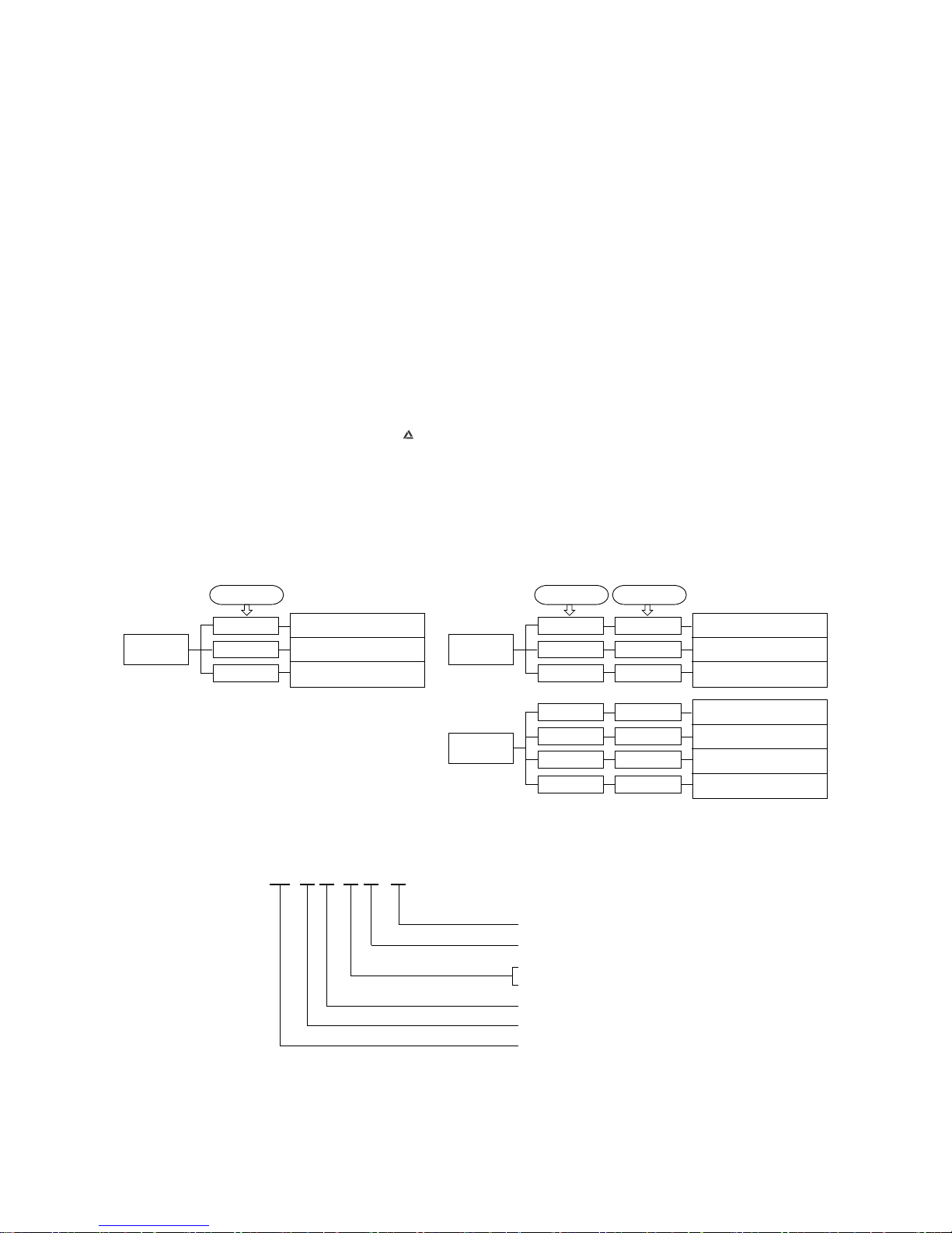
Serial signal transmission error
1 GENERAL INFORMATION
1.1 Specific features
The “Mitsubishi Daiya” room air-conditioner: SRK series are of split and wall mounted type and the unit consists of indoor unit and
outdoor unit with refrigerant precharged in factory. The indoor unit is composed of room air cooling or heating equipment with operation control switch and the outdoor unit is composed of condensing unit with compressor.
(1) Remote control flap
The flap can be automatically controlled by operating wireless remote controller.
¡ Air scroll: Flap operation is automatically control.
¡ Swing: This will swing the flap up and down.
¡ Memory flap: Once the flap position is set, the unit memorizes the position and continues to operate at the same position from
the next time.
(2) Automatic Operation
When the remote control switch is set on “auto( ) ”, it will either automatically decide operation mode such as cooling, heating
and thermal dry, or operate in the operation mode before it has been turned to automatic control.
(3) Self diagnosis function
¡ We are constantly trying to do better service to our customers by installing such judges that show abnormality of operation as
follows.
1.2 How to read the model name
Example : SR K 40 H D - S
Room temperature thermistor error
Indoor fan motor error
Heat exchanger thermistor error
2 time flash
6 time flash
TIMER lamp
ON
1 time flash
Outdoor unit heat exchanger
thermistor error
Discharge pipe thermistor error
Outdoor temperature thermistor
error
2 time flash
4 time flash
RUN lamp
keeps flashing
1 time flash
OFF
OFF
OFF
Outdoor unit error
Compressor overheat
Current cut
2 time flash
5 time flash
RUN lamp
ON
1 time flash
2 time flash
5 time flash
1 time flash
6 time flash 6 time flash
RUN lamp TIMER lamp Outdoor (LED)
R410A models
Series No.
H: Heat pump type
C: Cooling only type
Product capacity
Wall mounted type
Split type room air-conditioner
-
2
-
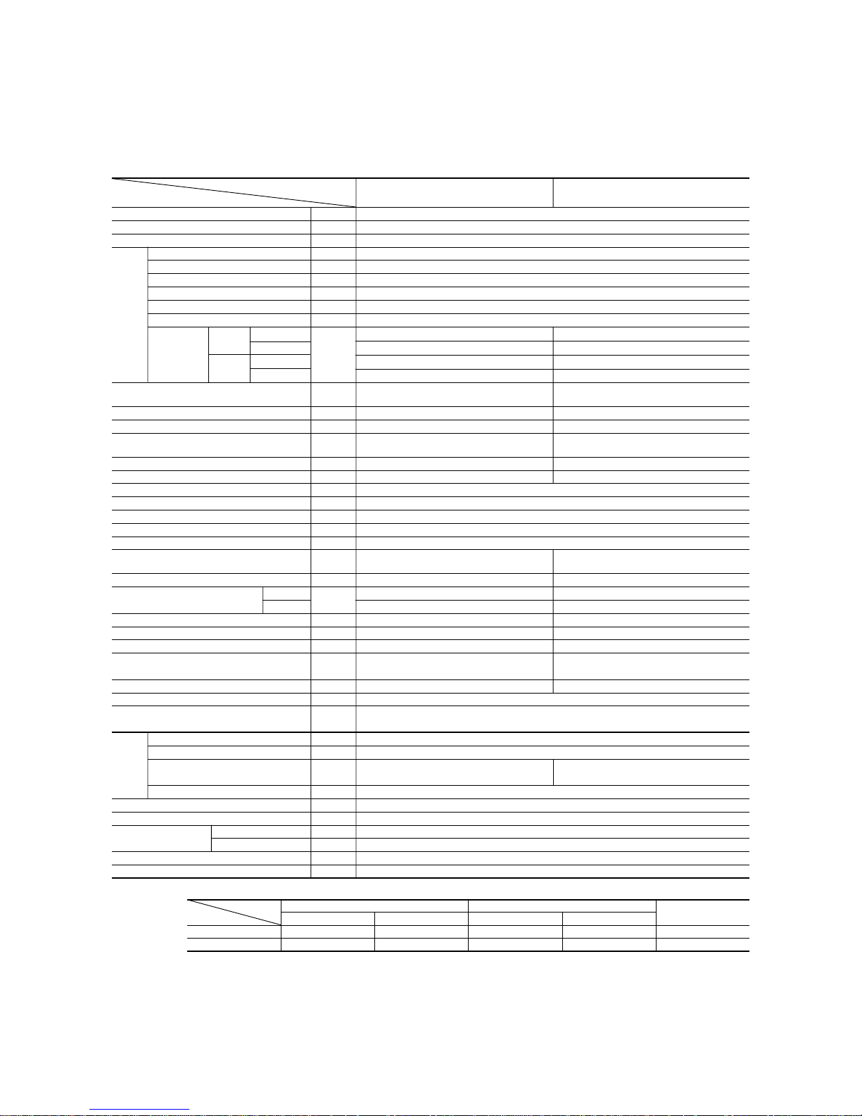
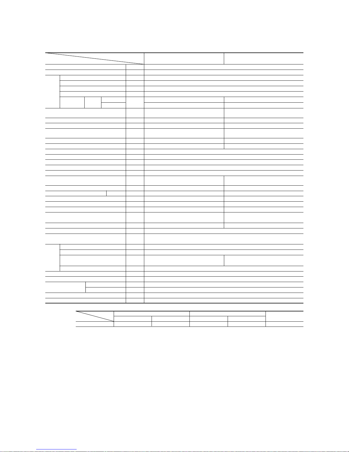
Item
Model
SRK20HD-S SRC20HD-S
Cooling capacity
(1)
W 2050
Heating capacity
(1)
W 2200
Power source 1 Phase, 220/230/240V, 50Hz
Cooling input kW 0.63
Running current (Cooling) A 3.1/3.0/2.9
Heating input kW 0.6
Running current (Heating) A 3.0/2.9/2.8
Inrush current A 18.9
COP Cooling: 3.21 Heating: 3.61
Cooling
sound level Hi 34, Me 28, Lo 26 46
Noise level
Power level
dB
52 60
Heating
sound level Hi 34, Me 31, Lo 27 46
Power level 52 60
Exterior dimensions
Height × Width × Depth
mm
250 × 815 × 249 540 × 720 × 290
Color Cool white Stucco white
Net weight kg 9.0 32
Refrigerant equipment
Compressor type & Q’ty
– RM-B5077MNE4 (Rotary type) × 1
Motor kW – 0.65
Starting method – Line starting
Heat exchanger Louver fins & inner grooved tubing
Refrigerant control Capillary tubes + Electronic expansion valve
Refrigerant
(3)
kg R410A 0.9 (Pre-Charged up to the piping length of 15m)
Refrigerant oil R 0.35 (MA68)
Deice control MC control
Air handling equipment
Fan type & Q’ty
Tangential fan × 1 Propeller fan × 1
Motor W 14 12
(Cooling) 7.5 26
Air flow (at High)
(Heating)
CMM
7.5 26
Air filter, Q’ty Polypropylene net (washable) × 2 –
Shock & vibration absorber – Cushion rubber (for compressor)
Electric heater ––
Operation control
Operation switch
Wireless-Remote controller –
Room temperature control MC. Thermostat –
Pilot lamp RUN (Green), TIMER (Yellow), HI POWER (Green), ECONO (Orange)
Safety equipment
O.D mm (in) Liquid line: φ6.35 (1/4″) Gas line: φ9.52 (3/8″)
Connecting method Flare connecting
Attached length of piping Liquid line: 0.4 m
Gas line : 0.33 m
–
Insulation Necessary (Both sides)
Drain hose Connectable
Power source cord 2.5 m (3 cores with Earth)
Size × Core number 1.5 mm2 × 4 cores (Including earth cable)
Connection wiring
Connecting method Terminal block (Screw fixing type)
Accessories (included) Mounting kit
Optional parts –
Notes (1) The data are measured at the following conditions.
2 SELECTION DATA
2.1 Specifications
Model SRK20HD-S (Indoor unit)
SRC20HD-S (Outdoor unit)
Item Indoor air temperature Outdoor air temperature
Standards
Operation DB WB DB WB
Cooling 27ºC19ºC35ºC24ºC ISO-T1, JIS C9612
Heating 20ºC – 7ºC6ºC ISO-T1, JIS C9612
(2) The operation data are applied to the 220/230/240V districts respectively.
(3) The refrigerant quantity to be charged includes the refrigerant in 15 m connecting piping.
(Purging is not required even in the short piping.)
Operation data
(1)
Refrigerant
piping
Compressor: Overheat protection, overcurrent protection, Serial signal error protection, Indoor fan motor error protection, Frost protection
The piping length is 7.5m.

-
3
-
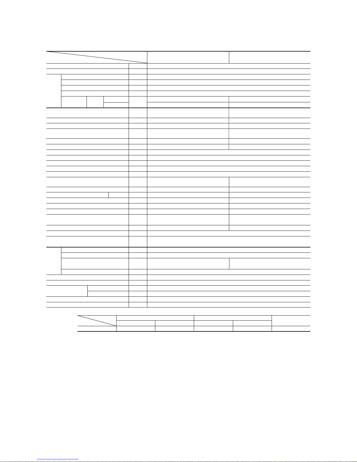
Item
Model
SRK28HD-S SRC28HD-S
Cooling capacity
(1)
W 2550
Heating capacity
(1)
W 2800
Power source 1 Phase, 220/230/240V, 50Hz
Cooling input kW 0.79
Running current (Cooling) A 3.9/3.7/3.5
Heating input kW 0.77
Running current (Heating) A 3.7/3.5/3.3
Inrush current A 17.2
COP Cooling: 3.21 Heating: 3.61
Cooling
sound level Hi 39, Me 33, Lo 30 46
Noise level
Power level
dB
55 60
Heating
sound level Hi 40, Me 33, Lo 29 46
Power level 56 60
Exterior dimensions
Height × Width × Depth
mm
250 × 815 × 249 540 × 720 × 290
Color Cool white Stucco white
Net weight kg 9.0 32
Refrigerant equipment
Compressor type & Q’ty
– 5PS102DAB [Rotary type] × 1
Motor kW – 0.7
Starting method – Line starting
Heat exchanger Louver fins & inner grooved tubing
Refrigerant control Capillary tubes + Electronic expansion valve
Refrigerant
(3)
kg R410A 0.9 (Pre-Charged up to the piping length of 15m)
Refrigerant oil R 0.35 (RB68A)
Deice control MC control
Air handling equipment
Fan type & Q’ty
Tangential fan × 1 Propeller fan × 1
Motor W 14 15
(Cooling) 8.0 30
Air flow (at High)
(Heating)
CMM
8.5 30
Air filter, Q’ty
Polypropylene net (washable) × 2
–
Shock & vibration absorber – Cushion rubber (for compressor)
Electric heater ––
Operation control
Operation switch
Wireless-Remote controller –
Room temperature control MC. Thermostat –
Pilot lamp RUN (Green), TIMER (Yellow), HI POWER (Green), ECONO (Orange)
Safety equipment
O.D mm (in) Liquid line: φ6.35 (1/4″) Gas line: φ9.52 (3/8″)
Connecting method Flare connecting
Attached length of piping Liquid line: 0.4 m
Gas line : 0.33 m
–
Insulation Necessary (Both sides)
Drain hose Connectable
Power source cord 2.5 m (3 cores with Earth)
Size × Core number 1.5 mm2 × 4 cores (Including earth cable)
Connection wiring
Connecting method Terminal block (Screw fixing type)
Accessories (included) Mounting kit
Optional parts –
Notes (1) The data are measured at the following conditions.
Model SRK28HD-S (Indoor unit)
SRC28HD-S (Outdoor unit)
Item Indoor air temperature Outdoor air temperature
Standards
Operation DB WB DB WB
Cooling 27ºC19ºC35ºC24ºC ISO-T1, JIS C9612
Heating 20ºC – 7ºC6ºC ISO-T1, JIS C9612
(2) The operation data are applied to the 220/230/240V districts respectively.
(3) The refrigerant quantity to be charged includes the refrigerant in 15 m connecting piping.
(Purging is not required even in the short piping.)
Operation data
(1)
Refrigerant
piping
Compressor: Overheat protection, overcurrent protection, Serial signal error protection, Indoor fan
motor error protection, Frost protection
The piping length is 7.5m.

-
4
-
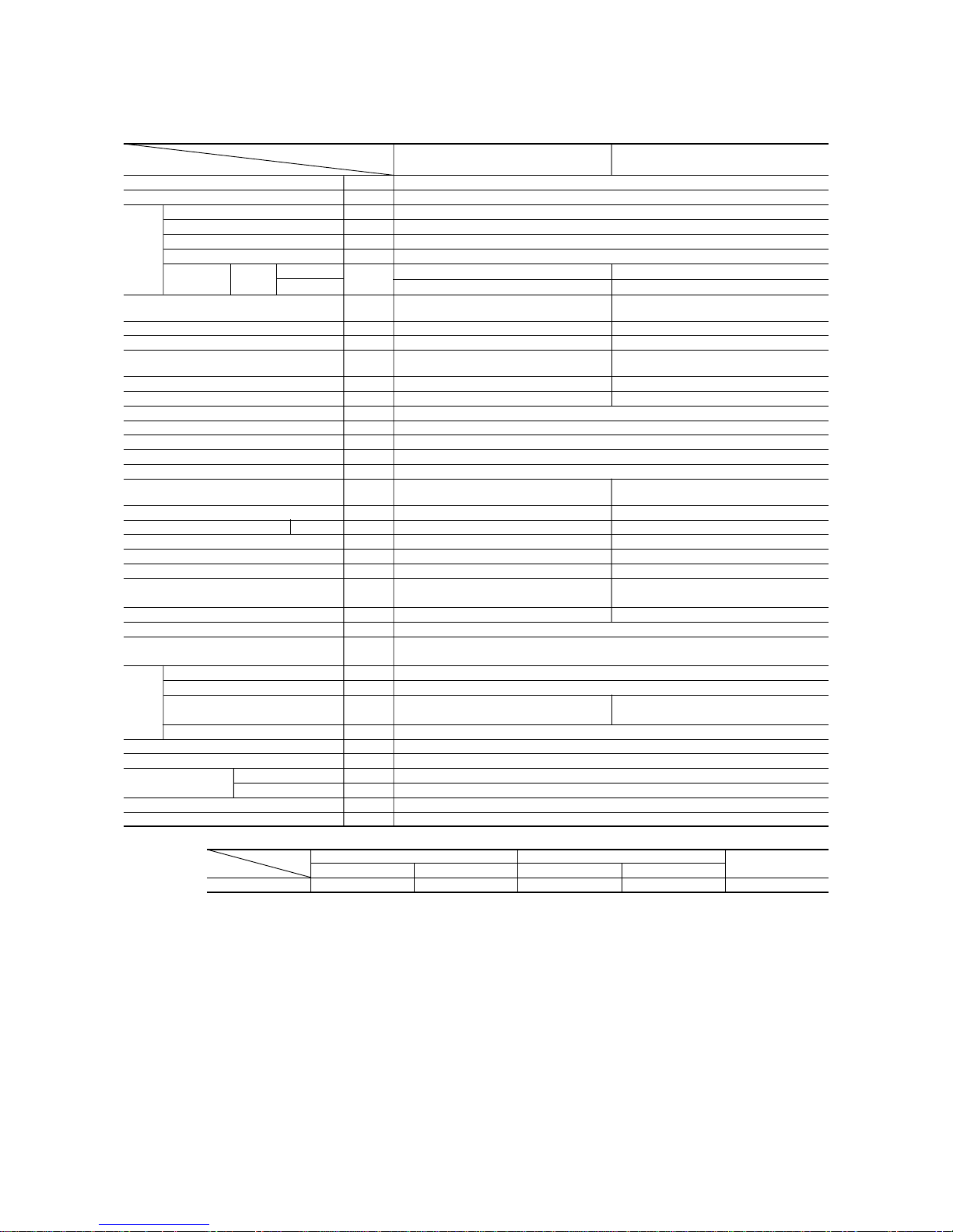
Model SRK40HD-S (Indoor unit)
SRC40HD-S (Outdoor unit)
Item
Model
SRK40HD-S SRC40HD-S
Cooling capacity
(1)
W 3600
Heating capacity
(1)
W 4000
Power source 1 Phase, 220/230/240V, 50Hz
Cooling input kW 1.12
Running current (Cooling) A 5.3/5.1/4.9
Heating input kW 1.16
Running current (Heating) A 5.5/5.3/5.1
Inrush current A 25.2
COP Cooling: 3.21 Heating: 3.42
Cooling
sound level Hi 40, Me 38, Lo 34 49
Noise level
Power level
dB
56 63
Heating
sound level Hi 41, Me 38, Lo 34 50
Power level 57 64
Exterior dimensions
Height × Width × Depth
mm
250 × 815 × 249 640 × 850 × 290
Color Cool white Stucco white
Net weight kg 9.0 41
Refrigerant equipment
Compressor type & Q’ty
– 5KS150DBB [Rotary type] × 1
Motor kW – 1.1
Starting method – Line starting
Heat exchanger Louver fins & inner grooved tubing
Refrigerant control Capillary tubes + Electronic expansion valve
Refrigerant
(3)
kg R410A 1.17 (Pre-Charged up to the piping length of 15m)
Refrigerant oil R 0.43 (RB68A)
Deice control MC control
Air handling equipment
Fan type & Q’ty
Tangential fan × 1 Propeller fan × 1
Motor W 14 35
(Cooling) 9.0 38
Air flow (at High)
(Heating)
CMM
9.5 38
Air filter, Q’ty
Polypropylene net (washable) × 2
–
Shock & vibration absorber – Cushion rubber (for compressor)
Electric heater ––
Operation control
Operation switch
Wireless-Remote controller –
Room temperature control MC. Thermostat –
Pilot lamp RUN (Green), TIMER (Yellow), HI POWER (Green), ECONO (Orange)
Safety equipment
O.D mm (in) Liquid line: φ6.35 (1/4″) Gas line: φ12.7 (1/2″)
Connecting method Flare connecting
Attached length of piping Liquid line: 0.4 m
Gas line : 0.33 m
–
Insulation Necessary (Both sides)
Drain hose Connectable
Power source cord 2.5 m (3 cores with Earth)
Size × Core number 1.5 mm2 × 4 cores (Including earth cable)
Connection wiring
Connecting method Terminal block (Screw fixing type)
Accessories (included) Mounting kit
Optional parts –
Notes (1) The data are measured at the following conditions.
Item Indoor air temperature Outdoor air temperature
Standards
Operation DB WB DB WB
Cooling 27ºC19ºC35ºC24ºC ISO-T1, JIS C9612
Heating 20ºC – 7ºC6ºC ISO-T1, JIS C9612
(2) The operation data are applied to the 220/230/240V districts respectively.
(3) The refrigerant quantity to be charged includes the refrigerant in 15 m connecting piping.
(Purging is not required even in the short piping.)
Operation data
(1)
Refrigerant
piping
Compressor: Overheat protection, overcurrent protection, Serial signal error protection, Indoor fan
motor error protection, Frost protection
The piping length is 7.5m.
-
5
-
Item
Model
SRK20CD-S SRC20CD-S
Cooling capacity
(1)
W 2050
Power source 1 Phase, 220/230/240V, 50Hz
Cooling input kW 0.63
Running current (Cooling) A 3.1/3.0/2.9
Inrush current A 18.9
COP Cooling: 3.21
Cooling
sound level Hi 34, Me 28, Lo 26 46
Noise level
Power level
dB
52 60
Exterior dimensions
Height × Width × Depth
mm
250 × 815 × 249 540 × 720 × 290
Color Cool white Stucco white
Net weight kg 9.0 32
Refrigerant equipment
Compressor type & Q’ty
– RM-B5077MNE4 (Rotary type) × 1
Motor kW – 0.65
Starting method – Line starting
Heat exchanger Louver fins & inner grooved tubing
Refrigerant control Capillary tubes + Electronic expansion valve
Refrigerant
(3)
kg R410A 0.9 (Pre-Charged up to the piping length of 15m)
Refrigerant oil R 0.35 (MA68)
Deice control MC control
Air handling equipment
Fan type & Q’ty
Tangential fan × 1 Propeller fan × 1
Motor W 14 12
Air flow (at High) (Cooling) CMM 7.5 26
Air filter, Q’ty Polypropylene net (washable) × 2 –
Shock & vibration absorber – Cushion rubber (for compressor)
Electric heater ––
Operation control
Operation switch
Wireless-Remote controller –
Room temperature control MC. Thermostat –
Pilot lamp RUN (Green), TIMER (Yellow), HI POWER (Green), ECONO (Orange)
Safety equipment
O.D mm (in) Liquid line: φ6.35 (1/4″) Gas line: φ9.52 (3/8″)
Connecting method Flare connecting
Attached length of piping Liquid line: 0.4 m
Gas line : 0.33 m
–
Insulation Necessary (Both sides)
Drain hose Connectable
Power source cord 2.5 m (3 cores with Earth)
Size × Core number 1.5 mm2 × 4 cores (Including earth cable)
Connection wiring
Connecting method Terminal block (Screw fixing type)
Accessories (included) Mounting kit
Optional parts –
Notes (1) The data are measured at the following conditions.
Model SRK20CD-S (Indoor unit)
SRC20CD-S (Outdoor unit)
Item Indoor air temperature Outdoor air temperature
Standards
Operation DB WB DB WB
Cooling 27ºC19ºC35ºC24ºC ISO-T1, JIS C9612
(2) The operation data are applied to the 220/230/240V districts respectively.
(3) The refrigerant quantity to be charged includes the refrigerant in 15 m connecting piping.
(Purging is not required even in the short piping.)
Operation data
(1)
Refrigerant
piping
Compressor: Overheat protection, overcurrent protection, Serial signal error protection, Indoor fan motor error protection, Frost protection
The piping length is 7.5m.
-
6
-
Item
Model
SRK28CD-S SRC28CD-S
Cooling capacity
(1)
W 2550
Power source 1 Phase, 220/230/240V, 50Hz
Cooling input kW 0.79
Running current (Cooling) A 3.9/3.7/3.5
Inrush current A 17.2
COP Cooling: 3.21
Cooling
sound level Hi 39, Me 33, Lo 30 46
Noise level
Power level
dB
55 60
Exterior dimensions
Height × Width × Depth
mm
250 × 815 × 249 540 × 720 × 290
Color Cool white Stucco white
Net weight kg 9.0 32
Refrigerant equipment
Compressor type & Q’ty
– 5PS102DAB [Rotary type] × 1
Motor kW – 0.7
Starting method – Line starting
Heat exchanger Louver fins & inner grooved tubing
Refrigerant control Capillary tubes + Electronic expansion valve
Refrigerant
(3)
kg R410A 0.9 (Pre-Charged up to the piping length of 15m)
Refrigerant oil R 0.35 (RB68A)
Deice control MC control
Air handling equipment
Fan type & Q’ty
Tangential fan × 1 Propeller fan × 1
Motor W 14 15
Air flow (at High) (Cooling) CMM 8.0 30
Air filter, Q’ty
Polypropylene net (washable) × 2
–
Shock & vibration absorber – Cushion rubber (for compressor)
Electric heater ––
Operation control
Operation switch
Wireless-Remote controller –
Room temperature control MC. Thermostat –
Pilot lamp RUN (Green), TIMER (Yellow), HI POWER (Green), ECONO (Orange)
Safety equipment
O.D mm (in) Liquid line: φ6.35 (1/4″) Gas line: φ9.52 (3/8″)
Connecting method Flare connecting
Attached length of piping Liquid line: 0.4 m
Gas line : 0.33 m
–
Insulation Necessary (Both sides)
Drain hose Connectable
Power source cord 2.5 m (3 cores with Earth)
Size × Core number 1.5 mm2 × 4 cores (Including earth cable)
Connection wiring
Connecting method Terminal block (Screw fixing type)
Accessories (included) Mounting kit
Optional parts –
Notes (1) The data are measured at the following conditions.
Model SRK28CD-S (Indoor unit)
SRC28CD-S (Outdoor unit)
Item Indoor air temperature Outdoor air temperature
Standards
Operation DB WB DB WB
Cooling 27ºC19ºC35ºC24ºC ISO-T1, JIS C9612
(2) The operation data are applied to the 220/230/240V districts respectively.
(3) The refrigerant quantity to be charged includes the refrigerant in 15 m connecting piping.
(Purging is not required even in the short piping.)
Operation data
(1)
Refrigerant
piping
Compressor: Overheat protection, overcurrent protection, Serial signal error protection, Indoor fan
motor error protection, Frost protection
The piping length is 7.5m.
-
7
-
Item
Model
SRK40CD-S SRC40CD-S
Cooling capacity
(1)
W 3600
Power source 1 Phase, 220/230/240V, 50Hz
Cooling input kW 1.12
Running current (Cooling) A 5.3/5.1/4.9
Inrush current A 25.2
COP Cooling: 3.21
Cooling
sound level Hi 40, Me 38, Lo 34 49
Noise level
Power level
dB
56 63
Exterior dimensions
Height × Width × Depth
mm
250 × 815 × 249 640 × 850 × 290
Color Cool white Stucco white
Net weight kg 9.0 41
Refrigerant equipment
Compressor type & Q’ty
– 5KS150DBB [Rotary type] × 1
Motor kW – 1.1
Starting method – Line starting
Heat exchanger Louver fins & inner grooved tubing
Refrigerant control Capillary tubes + Electronic expansion valve
Refrigerant
(3)
kg R410A 1.17 (Pre-Charged up to the piping length of 15m)
Refrigerant oil R 0.43 (RB68A)
Deice control MC control
Air handling equipment
Fan type & Q’ty
Tangential fan × 1 Propeller fan × 1
Motor W 14 35
Air flow (at High) (Cooling) CMM 9.0 38
Air filter, Q’ty
Polypropylene net (washable) × 2
–
Shock & vibration absorber – Cushion rubber (for compressor)
Electric heater ––
Operation control
Operation switch
Wireless-Remote controller –
Room temperature control MC. Thermostat –
Pilot lamp RUN (Green), TIMER (Yellow), HI POWER (Green), ECONO (Orange)
Safety equipment
O.D mm (in) Liquid line: φ6.35 (1/4″) Gas line: φ12.7 (1/2″)
Connecting method Flare connecting
Attached length of piping Liquid line: 0.4 m
Gas line : 0.33 m
–
Insulation Necessary (Both sides)
Drain hose Connectable
Power source cord 2.5 m (3 cores with Earth)
Size × Core number 1.5 mm2 × 4 cores (Including earth cable)
Connection wiring
Connecting method Terminal block (Screw fixing type)
Accessories (included) Mounting kit
Optional parts –
Notes (1) The data are measured at the following conditions.
Model SRK40CD-S (Indoor unit)
SRC40CD-S (Outdoor unit)
Item Indoor air temperature Outdoor air temperature
Standards
Operation DB WB DB WB
Cooling 27ºC19ºC35ºC24ºC ISO-T1, JIS C9612
(2) The operation data are applied to the 220/230/240V districts respectively.
(3) The refrigerant quantity to be charged includes the refrigerant in 15 m connecting piping.
(Purging is not required even in the short piping.)
Operation data
(1)
Refrigerant
piping
Compressor: Overheat protection, overcurrent protection, Serial signal error protection, Indoor fan
motor error protection, Frost protection
The piping length is 7.5m.
-
8
-
2.2 Range of usage & limitations
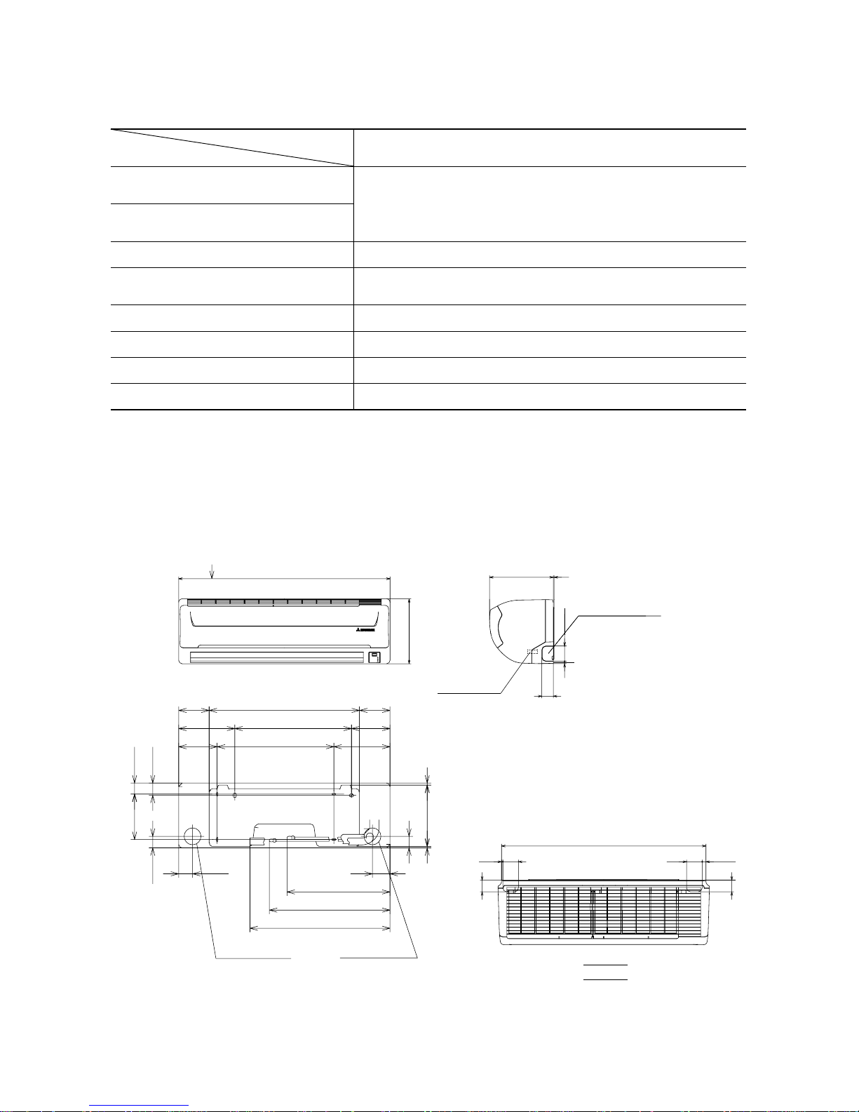
2.3 Exterior dimensions
Indoor return air temperature
(Upper, lower limits)
Refrigerant line (one way) length Max. 15m
All models
Refer to the selection chart
Power source voltage Rating ± 10%
Voltage at starting Min. 85% of rating
Frequency of ON-OFF cycle Max. 10 times/h
ON and OFF interval Max. 3 minutes
Outdoor air temperature
(Upper, lower limits)
Vertical height difference between
outdoor unit and indoor unit
Max. 10m (Outdoor unit is higher)
Max. 10m (Outdoor unit is lower)
Item
Models
(1) Indoor unit
Models All models
VIEW A
117.5
580 117.5
148.5
216.5216.5
8.2
44.5
236.1
5.7
450
450
67.5
42.7
47.2
175
44.5
216.5216.5
148.5
53.5
Piping for Gas
Drain hose 540 (ø16)
Piping for Liquid 465.1 (ø6.35)
Piping hole (ø65)
Piping hole (ø65)
( )
20.28: ø9.52
40: ø12.7
397.1
45
14.5
60
788
5
60
45
815
A
250
Unit: mm
Piping hole right(left)
Terminal block
9
60
45
3
249
-
9
-
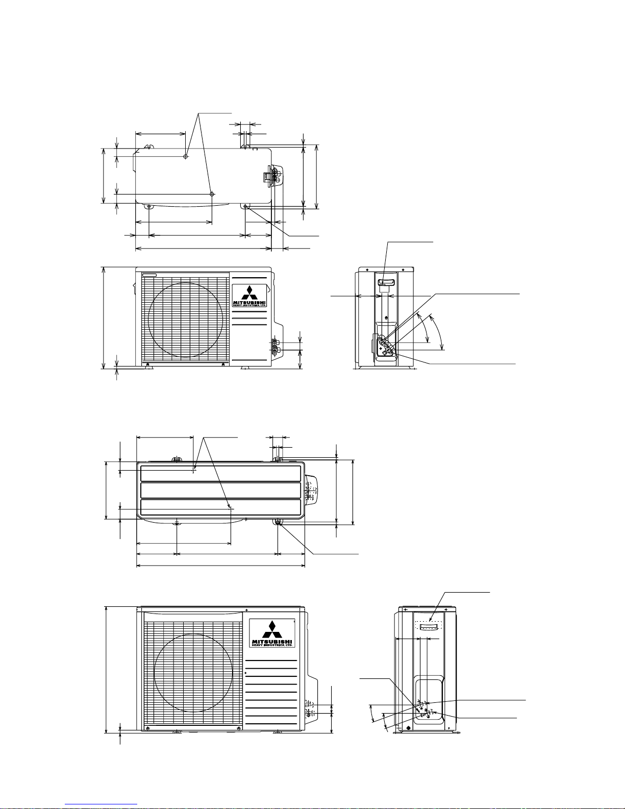
(2) Outdoor unit
Models SRC20HD-S, 28HD-S, 20CD-S, 28CD-S
Drain hole
286.4
12
50
290
49.6
43.5
850
203.1
510 136.9
476
Elogated hole
(2-12x16)
314
12
328
Terminal block
Service valve (Liquide)
ø6.35 (1/4'')
Service valve (Gas)
ø12.7 (1/2'')
Ground
terminal
124
34.6
20˚
20˚
42.7
100.3
15
640
14
Models SRC40HD-S, 40CD-S
Unit: mm
290
540
14.4
47.4 42.6
264.5
71
404.5
510
720
17.8
Drain holes
50
12
39.7
99.9
340
312.5
13.5
14
139
2-16x12
61.9
139.3 33.3
Flare connecting ø6.35 (1/4")
Service valve (Liquid)
40
°
40
°
Flare connecting ø9.52 (3/8")
Service valve (Gas)
Terminal block
-
10
-
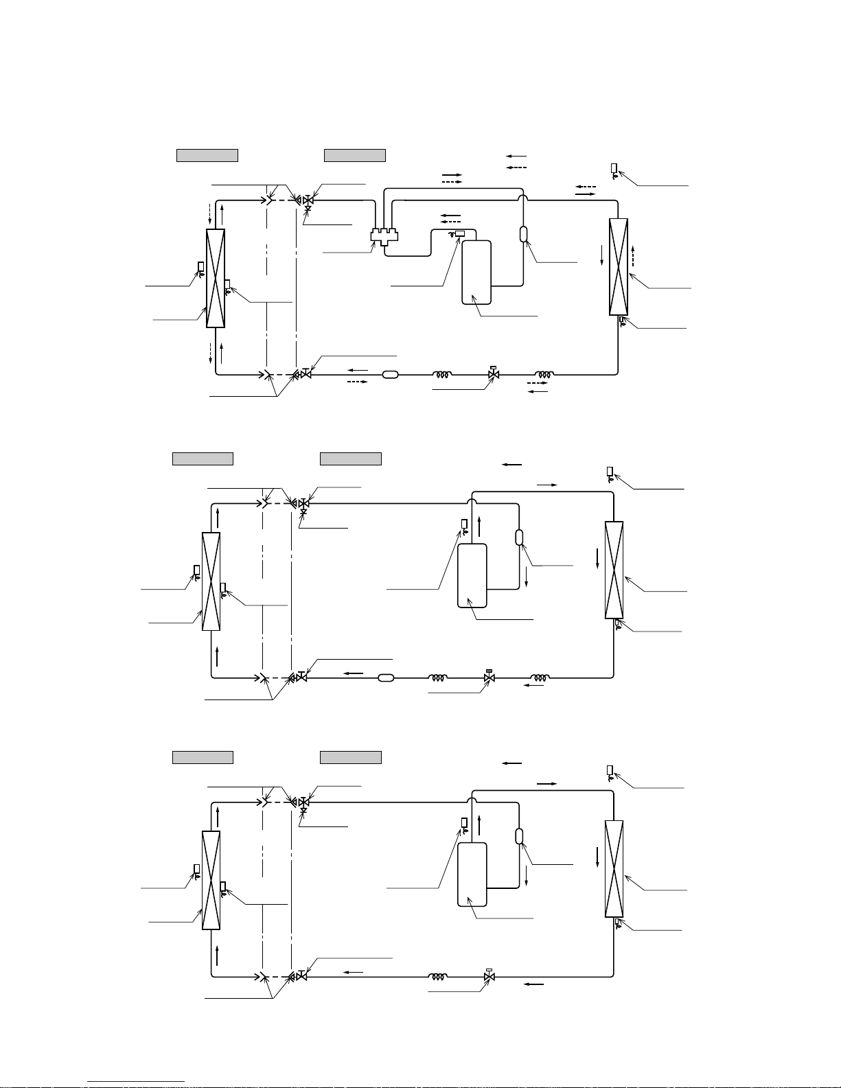
2.4 Piping system
Models SRK20HD-S, 28HD-S, 40HD-S
Models SRK20CD-S, 28CD-S
Model SRK40CD-S
Outdoor unitIndoor unit
Heat
exchanger
Room temp.
thermistor
Heat
exchanger
Flare connecting
Heat
exchanger
thermistor
Piping
(Liquid)
ø6.35
Check joint
4 way valve
Service valve (Liquid)
Flare connecting
Discharge temp.
thermistor
Cooling cycle
Heating cycle
Outdoor air
temp. thermistor
Heat exchanger
thermistor
Compressor
Capillary tube
Strainer
Accumulator
Service valve
(Gas)
Capillary tube
Electronic
expansion valve
( )
Piping
(Gas)
20, 28 : ø9.52
40 : ø12.7
Outdoor unitIndoor unit
Room temp.
thermistor
Heat
exchanger
Flare connecting
Heat
exchanger
thermistor
Piping
(Liquid)
ø6.35
Check joint
Service valve (Liquid)
Flare connecting
Discharge temp.
thermistor
Cooling cycle
Outdoor air
temp. thermistor
Heat
exchanger
Heat exchanger
thermistor
Compressor
Capillary tube
Strainer
Accumulator
Service valve
(Gas)
Capillary tube
Electronic
expansion valve
Piping
(Gas)
ø9.52
Outdoor unitIndoor unit
Room temp.
thermistor
Heat
exchanger
Flare connecting
Heat
exchanger
thermistor
Piping
(Liquid)
ø6.35
Check joint
Service valve (Liquid)
Flare connecting
Discharge temp.
thermistor
Cooling cycle
Outdoor air
temp. thermistor
Heat
exchanger
Heat exchanger
thermistor
Compressor
Capillary tube
Accumulator
Service valve
(Gas)
Electronic
expansion valve
Piping
(Gas)
ø12.7
-
11
-
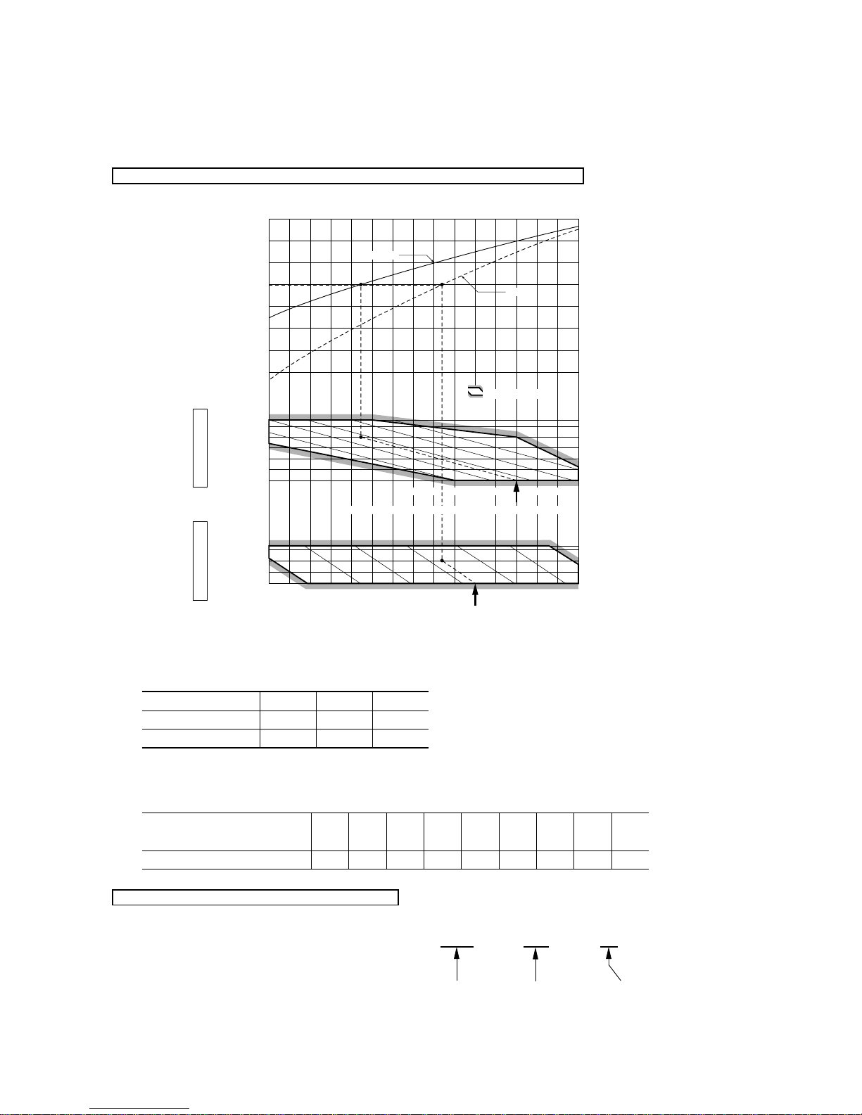
2.5 Selection chart
Correct the cooling and heating capacity in accordance with the conditions as follows. The net cooling and heating capacity can be
obtained in the following way.
Net capacity = Capacity shown on specification ✕ Correction factors as follows.
(1) Coefficient of cooling and heating capacity in relation to temperatures
(2) Correction of cooling and heating capacity in relation to one way length of refrigerant piping
It is necessary to correct the cooling and heating capacity in relation to the one way piping length between the indoor and outdoor
units.
(3) Correction relative to frosting on outdoor heat exchanger during heating
In additions to the foregoing corrections (1), (2) the heating capacity needs to be adjusted also with respect to the frosting on the
outdoor heat exchanger.
How to obtain the cooling and heating capacity
Example : The net cooling capacity of the model SRK40HD-S with the piping length of 15m, indoor wet-bulb temperature at 19.0˚C
and outdoor dry-bulb temperature 35˚C is Net cooling capacity = 3600 ✕ 0.975 ✕ 1.0 = 3510 w
SRK40HD-S Length 15m
Factor by air
temperatures
15
ISO-T1 Standard ConditionOutdoor air W.B. temperature °C W.B.
010-10 -5 5
14 16 18 20 22
15
10
27
25
20
15
20
25
30
35
40
0.6
0.7
0.8
0.9
1.0
1.1
1.2
1.3
43
24
20
ISO-T1 Standard ConditionIndoor air W.B. temperature °C W.B.
Heating
Cooling
Applicable range
Coefficient of cooling &
Heating capacity in
relation to temperature
Cooling operation
Outdoor air D.B.
temperature
°C D.B.
Heating operation
Indoor air D.B.
temperature
°C D.B.
Piping length [m]
Cooling
Heating
7
1.0
1.0
10
0.99
1.0
15
0.975
1.0
Air inlet temperature of
outdoor unit in ˚C WB
Adjustment coefficient
-10
0.95-90.94-70.93-50.91-30.88-10.8610.8730.9251.00
 Loading...