

Mitsubishi Heavy Industries SRK25ZSX-S, SRK35ZSX-S, SRK20ZS-SB, SRK25ZS-SB, SRK20ZS-S Technical Manual
...
Manual No.'17•SRK-T-203
updated April 10, 2017
TECHNICAL MANUAL
INVERTER WALL MOUNTED TYPE
RESIDENTIAL AIR-CONDITIONERS
(Split system, air to air heat pump type)
SRK20ZSX-S
25ZSX-S
35ZSX-S
50ZSX-S
60ZSX-S

'17 • SRK-T-203
'10 • SRK-T-105
CONTENTS
1. SPECIFICATIONS ........................................................................................ 3
2. EXTERIOR DIMENSIONS
......................................................................... 8
(1) Indoor units .......................................................................................... 8
(2) Outdoor units ....................................................................................... 9
(3) Remote control
..................................................................................... 11
3. ELECTRICAL WIRING .............................................................................. 13
(1) Indoor units .......................................................................................... 13
(2) Outdoor units ....................................................................................... 14
4. NOISE LEVEL ............................................................................................ 16
5. PIPING SYSTEM ...................................................................................... 21
6. RANGE OF USAGE & LIMITATIONS
7. CAPACITY TABLES
8. APPLICATION DATA
................................................................................... 24
.................................................................................. 26
..................................................... 22
(1) Installation of indoor unit ...................................................................... 26
(2) Installation of outdoor unit .................................................................. 30
9. OUTLINE OF OPERATION CONTROL BY MICROCOMPUTER ............... 34
(1) Operation control function by wireless remote control
(2) Unit ON/OFF button
........................................................................... 35
....................... 34
......................................................................... 35(3) Auto restart function
(4) Installing two air-conditioners in the same room
............................... 35
(5) Selection of the annual cooling function .............................................. 36
(6) Heating only function ........................................................................... 36
(7) High power operation ........................................................................... 36
(8) Economy operation
.............................................................................. 37
(9) Airflow direction adjustment .................................................................... 37
(10) 3D auto operation
(11) Timer operation
........................................................................... 38
.................................................................................. 39
(12) Silent operation .................................................................................... 40
(13) Night setback operation
..................................................................... 40
(14) Airflow range setting ........................................................................... 40
(15) Display brightness adjustment
(16) Auto OFF operation
............................................................................ 41
............................................................... 41
(17) Outline of heating operation
(18) Outline of cooling operation
(19) Outline of dehumidifying (DRY) opertaion
(20) Outline of automatic operation
(21) Protective control function
............................................................... 41
............................................................... 43
........................................... 43
............................................................... 44
................................................................... 44
-
-
1

'17 • SRK-T-203
'13 • SRK-T-135
10. MAINTENANCE DATA
(1) Cautions
............................................................................................. 51
............................................................................... 51
(2) Items to check before troubleshooting ................................................. 51
(3) Troubleshooting procedure
(4) Troubleshooting procedure (If the air-conditioner runs)
(5) Self-diagnosis table ............................................................................. 53
(If the air-conditioner does not run at all)
..................... 52
(6) Service mode (Trouble mode access function) ................................... 54
(7) Inspection procedures corresponding to detail of trouble .................... 62
Phenomenon observed after shortcircuit, wire breakage on sensor
(8)
(9) Checking the indoor electrical equipment
........................................... 67
......... 67
(10) How to make sure of wireless remote control ...................................... 69
(11) Inspection procedure for blown fuse on the indoor and outdoor PCB .... 69
(12) Outdoor unit inspection points .............................................................. 70
11. INDOOR UNIT DISASSEMBLY PROCEDURE
12. OPTION PARTS
(1) Wired remote control (RC-E5)
(2) Interface kit (SC-BIKN-E)
........................................................................................... 79
.............................................................. 79
..................................................................... 85
............................................ 73
(3) Superlink E board (SC-ADNA-E) .......................................................... 89
........ 51
13. TECHNICAL INFORMATION
■How to read the model name
Example: SRK 20 Z
SX-S
....................................................................... 91
Series code
Inverter type
Product capacity (Cooling capacity : 2.0kW)
Model name SRK : Wall mounted type
SRC : Outdoor unit
-
-
2

'17 • SRK-T-203
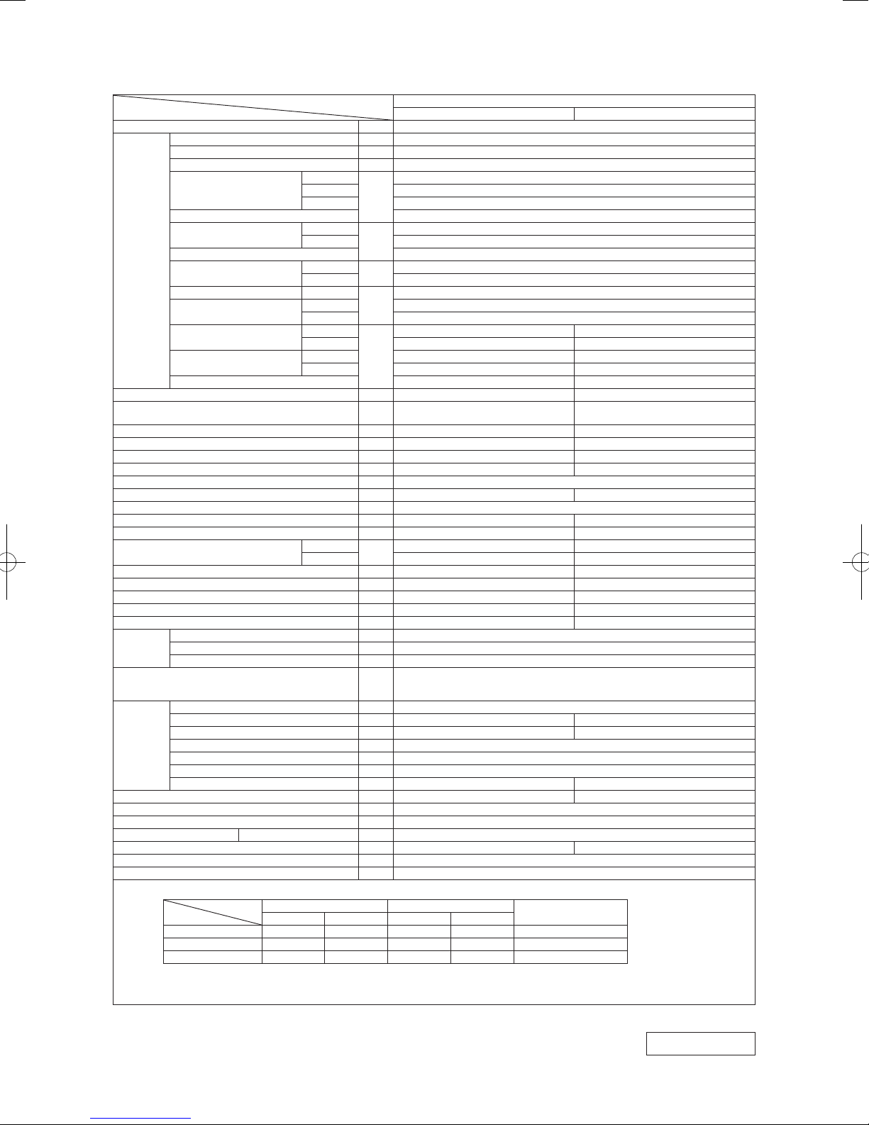
1. SPECIFICATIONS
Item
Power source 1 Phase, 220 - 240V, 50Hz / 220V, 60Hz
Operation
data
Exterior dimensions (Height x Width x Depth) mm 305 x 920 x 220 640 x 800 (+71) x 290
Exterior appearance
(Equivalent color)
Net weight kg 13 43.0
Compressor type & Quantity — RMT5111MCE2(Twin rotary type) x 1
Compressor motor (Starting method) kW — 0.75 (Inverter driven)
Refrigerant oil (Amount, type) ℓ — 0.35 (DIAMOND FREEZE MA68)
Refrigerant (Type, amount, pre-charge length) kg R410A 1.45 in outdoor unit (Incl. the amount for the piping of 15m)
Heat exchanger Louver fins & inner grooved tubing M fins & inner grooved tubing
Refrigerant control Capillary tubes + Electronic expansion valve
Fan type & Quantity Tangential fan x 1 Propeller fan x 1
Fan motor (Starting method) W 42 x1 (Direct drive) 34 x1 (Direct drive)
Air flow
Available external static pressure Pa 0 0
Outside air intake Not possible —
Air filter, Quality / Quantity Polypropylene net (Washable) x 2 —
Shock & vibration absorber Rubber sleeve (for fan motor)
Electric heater — —
Operation
control
Safety equipments
Installation
data
Drain pump, max lift height mm — —
Recommended breaker size A 16
L.R.A. (Locked rotor ampere) A 2.5
Interconnecting wires Size x Core number 1.5mm
IP number IPX0 IPX4
Standard accessories
Option parts Interface kit (SC-BIKN-E)
Nominal cooling capacity (range) kW 2.0 ( 0.9(Min.) - 3.2 (Max.))
Nominal heating capacity (range) kW 2.7 ( 0.8(Min.) - 5.3 (Max.))
Heating capacity (H2) kW —
Power consumption
Max power consumption 1.92
Running current
Inrush current, max current 2.5 Max. 9
Power factor
EER Cooling 6.25
COP
Sound power level
Sound pressure level
Silent mode sound pressure level — Cooling:33 / Heating:38
Remote control Wireless - remote control
Room temperature control Microcomputer thermostat
Operation display RUN: Green, TIMER: Yellow, ECO: Blue
Refrigerant piping size (O.D) mm Liquid line: φ6.35 (1/4") Gas line: φ9.52 (3/8")
Connecting method Flare connection Flare connection
Attached length of piping m Liquid line : 0.55 / Gas line : 0.48 —
Insulation for piping Necessary (Both sides), independent
Refrigerant line (one way) length m Max.25
Vertical height diff. between O.U. and I.U. m Max.15 (Outdoor unit is higher) / Max.15 (Outdoor unit is lower)
Drain hose Hose connectable (VP 16) Holes φ20 x 5 pcs
Cooling
Heating 0.47 (0.14 - 1.36)
Heating (H2) —
Cooling
Heating 2.6 / 2.5 / 2.4 (220/ 230/ 240V)
Cooling
Heating 81
Heating 5.74
Heating (H2) —
Cooling
Heating 53 58
Cooling Hi: 38 Me: 31 Lo: 24 ULo: 19 43
Heating Hi: 38 Me: 32 Lo: 25 ULo: 19 44
Cooling
Heating Hi: 12.2 Me: 10.3 Lo: 7.2 ULo: 5.4 31.0
Model
kW
A
%
dB(A)
3
m
/min
Indoor unit SRK20ZSX-S Outdoor unit SRC20ZSX-S
53 56
Munsell : (8.0Y 9.3/0.1), RAL : 9003
Hi: 11.3 Me: 9.1 Lo: 6.0 ULo: 5.0 31.0
Frost protection, Serial signal error protection, Indoor fan motor error protection,
Heating overload protection( High pressure control ), Cooling overload protection
Mounting kit, Clean filter (Allergen clear filter x 1, Photocatalytic washable deodorizing filter x 1)
Fine snow
Compressor overheat protection, Overcurrent protection,
2
x 4 cores (Including earth cable) / Terminal block (Screw fixing type)
Notes (1) The data are measured at the following conditions.
Indoor air temperature Outdoor air temperature
Operation
Cooling 27˚C 19˚C 35˚C 24˚C ISO5151-T1
Heating 20˚C — 7˚C 6˚C ISO5151-H1
Heating (H2) 20˚C — 2˚C 1˚C ISO5151-H2
(2) This air-conditioner is manufactured and tested in conformity with the ISO.
(3) Sound level indicates the value in an anechoic chamber. During operation these values are somewhat higher due to ambient conditions.
(4) Select the breaker size according to the own national standard.
Item
DB WB DB WB
SRK20ZSX-S
0.32 (0.16 - 0.74)
1.9 / 1.8 / 1.7 (220/ 230/ 240V)
76
Munsell : (4.2Y 7.5/1.1), RAL : 7004
Rubber sleeve (for fan motor & compressor)
The pipe length is 5m.
Standards
Stucco white
RWA000Z269
-
-
3

'17 • SRK-T-203
Item
Power source 1 Phase, 220 - 240V, 50Hz / 220V, 60Hz
Operation
data
Exterior dimensions (Height x Width x Depth) mm 305 x 920 x 220 640 x 800 (+71) x 290
Exterior appearance
(Equivalent color)
Net weight kg 13 43.0
Compressor type & Quantity — RMT5111MCE2(Twin rotary type) x 1
Compressor motor (Starting method) kW — 0.75 (Inverter driven)
Refrigerant oil (Amount, type) ℓ — 0.35 (DIAMOND FREEZE MA68)
Refrigerant (Type, amount, pre-charge length) kg R410A 1.45 in outdoor unit (Incl. the amount for the piping of 15m)
Heat exchanger Louver fins & inner grooved tubing M fins & inner grooved tubing
Refrigerant control Capillary tubes + Electronic expansion valve
Fan type & Quantity Tangential fan x 1 Propeller fan x 1
Fan motor (Starting method) W 42 x1 (Direct drive) 34 x1 (Direct drive)
Air flow
Available external static pressure Pa 0 0
Outside air intake Not possible —
Air filter, Quality / Quantity Polypropylene net (Washable) x 2 —
Shock & vibration absorber Rubber sleeve (for fan motor)
Electric heater — —
Operation
control
Safety equipments
Installation
data
Drain pump, max lift height mm — —
Recommended breaker size A 16
L.R.A. (Locked rotor ampere) A 3.0
Interconnecting wires Size x Core number 1.5mm
IP number IPX0 IPX4
Standard accessories
Option parts Interface kit (SC-BIKN-E)
Nominal cooling capacity (range) kW 2.5 ( 0.9(Min.) - 3.7 (Max.))
Nominal heating capacity (range) kW 3.2 ( 0.8(Min.) - 5.8 (Max.))
Heating capacity (H2) kW —
Power consumption
Max power consumption 1.92
Running current
Inrush current, max current 3.0 Max. 9
Power factor
EER Cooling 5.68
COP
Sound power level
Sound pressure level
Silent mode sound pressure level — Cooling:35 / Heating:39
Remote control Wireless - remote control
Room temperature control Microcomputer thermostat
Operation display RUN: Green, TIMER: Yellow, ECO: Blue
Refrigerant piping size (O.D) mm Liquid line: φ6.35 (1/4") Gas line: φ9.52 (3/8")
Connecting method Flare connection Flare connection
Attached length of piping m Liquid line : 0.55 / Gas line : 0.48 —
Insulation for piping Necessary (Both sides), independent
Refrigerant line (one way) length m Max.25
Vertical height diff. between O.U. and I.U. m Max.15 (Outdoor unit is higher) / Max.15 (Outdoor unit is lower)
Drain hose Hose connectable (VP 16) Holes φ20 x 5 pcs
Cooling
Heating 0.59 (0.14 - 1.54)
Heating (H2) —
Cooling
Heating 3.2 / 3.0 / 2.9 (220/ 230/ 240V)
Cooling
Heating 85
Heating 5.42
Heating (H2) —
Cooling
Heating 56 58
Cooling Hi: 39 Me: 33 Lo: 25 ULo: 19 44
Heating Hi: 40 Me: 34 Lo: 27 ULo: 19 45
Cooling
Heating Hi: 12.8 Me: 11.0 Lo: 7.8 ULo: 5.4 31.0
Model
kW
A
%
dB(A)
3
m
/min
Indoor unit SRK25ZSX-S Outdoor unit SRC25ZSX-S
55 57
Munsell : (8.0Y 9.3/0.1), RAL : 9003
Hi: 12.2 Me: 10.0 Lo: 6.7 ULo: 5.0 31.0
Frost protection, Serial signal error protection, Indoor fan motor error protection,
Heating overload protection( High pressure control ), Cooling overload protection
Mounting kit, Clean filter (Allergen clear filter x 1, Photocatalytic washable deodorizing filter x 1)
Fine snow
Compressor overheat protection, Overcurrent protection,
2
x 4 cores (Including earth cable) / Terminal block (Screw fixing type)
Notes (1) The data are measured at the following conditions.
Indoor air temperature Outdoor air temperature
Operation
Cooling 27˚C 19˚C 35˚C 24˚C ISO5151-T1
Heating 20˚C — 7˚C 6˚C ISO5151-H1
Heating (H2) 20˚C — 2˚C 1˚C ISO5151-H2
(2) This air-conditioner is manufactured and tested in conformity with the ISO.
(3) Sound level indicates the value in an anechoic chamber. During operation these values are somewhat higher due to ambient conditions.
(4) Select the breaker size according to the own national standard.
Item
DB WB DB WB
SRK25ZSX-S
0.44 (0.16 - 0.89)
2.5 / 2.4 / 2.3 (220/ 230/ 240V)
80
Munsell : (4.2Y 7.5/1.1), RAL : 7004
Rubber sleeve (for fan motor & compressor)
The pipe length is 5m.
Standards
Stucco white
RWA000Z269
-
-
4
'17 • SRK-T-203
Item
Power source 1 Phase, 220 - 240V, 50Hz / 220V, 60Hz
Operation
data
Exterior dimensions (Height x Width x Depth) mm 305 x 920 x 220 640 x 800(+71) x 290
Exterior appearance
(Equivalent color)
Net weight kg 13 43.0
Compressor type & Quantity — RMT5111MCE2(Twin rotary type) x 1
Compressor motor (Starting method) kW — 0.90 (Inverter driven)
Refrigerant oil (Amount, type) ℓ — 0.35 (DIAMOND FREEZE MA68)
Refrigerant (Type, amount, pre-charge length) kg R410A 1.45 in outdoor unit (Incl. the amount for the piping of 15m)
Heat exchanger Louver fins & inner grooved tubing M fins & inner grooved tubing
Refrigerant control Capillary tubes + Electronic expansion valve
Fan type & Quantity Tangential fan x 1 Propeller fan x 1
Fan motor (Starting method) W 42 x1 (Direct drive) 34 x1 (Direct drive)
Air flow
Available external static pressure Pa 0 0
Outside air intake Not possible —
Air filter, Quality / Quantity Polypropylene net (Washable) x 2 —
Shock & vibration absorber Rubber sleeve (for fan motor)
Electric heater — —
Operation
control
Safety equipments
Installation
data
Drain pump, max lift height mm — —
Recommended breaker size A 16
L.R.A. (Locked rotor ampere) A 4.3
Interconnecting wires Size x Core number 1.5mm
IP number IPX0 IPX4
Standard accessories
Option parts Interface kit (SC-BIKN-E)
Nominal cooling capacity (range) kW 3.5 ( 0.9(Min.) - 4.3 (Max.))
Nominal heating capacity (range) kW 4.3 ( 0.8(Min.) - 6.6 (Max.))
Heating capacity (H2) kW —
Power consumption
Max power consumption 1.92
Running current
Inrush current, max current 4.3 Max. 9
Power factor
EER Cooling 4.49
COP
Sound power level
Sound pressure level
Silent mode sound pressure level — Cooling:38 / Heating:43
Remote control Wireless - remote control
Room temperature control Microcomputer thermostat
Operation display RUN: Green, TIMER: Yellow, ECO: Blue
Refrigerant piping size (O.D) mm Liquid line: φ6.35 (1/4") Gas line: φ9.52 (3/8")
Connecting method Flare connection Flare connection
Attached length of piping m Liquid line : 0.55 / Gas line : 0.48 —
Insulation for piping Necessary (Both sides), independent
Refrigerant line (one way) length m Max.25
Vertical height diff. between O.U. and I.U. m Max.15 (Outdoor unit is higher) / Max.15 (Outdoor unit is lower)
Drain hose Hose connectable (VP 16) Holes φ20 x 5 pcs
Cooling
Heating 0.90 (0.14 - 1.89)
Heating (H2) —
Cooling
Heating 4.4 / 4.3 / 4.1 (220/ 230/ 240V)
Cooling
Heating 92
Heating 4.78
Heating (H2) —
Cooling
Heating 58 62
Cooling Hi: 43 Me: 35 Lo: 26 ULo: 19 48
Heating Hi: 41 Me: 35 Lo: 28 ULo: 19 47
Cooling
Heating Hi: 13.9 Me: 11.8 Lo: 8.6 ULo: 5.4 31.0
Model
kW
A
%
dB(A)
3
m
/min
Indoor unit SRK35ZSX-S Outdoor unit SRC35ZSX-S
58 61
Munsell : (8.0Y 9.3/0.1), RAL : 9003
Hi: 13.1 Me: 10.8 Lo: 7.3 ULo: 5.0 36.0
Frost protection, Serial signal error protection, Indoor fan motor error protection,
Heating overload protection( High pressure control ), Cooling overload protection
Mounting kit, Clean filter (Allergen clear filter x 1, Photocatalytic washable deodorizing filter x 1)
Fine snow
Compressor overheat protection, Overcurrent protection,
2
x 4 cores (Including earth cable) / Terminal block (Screw fixing type)
Notes (1) The data are measured at the following conditions.
Indoor air temperature Outdoor air temperature
Operation
Cooling 27˚C 19˚C 35˚C 24˚C ISO5151-T1
Heating 20˚C — 7˚C 6˚C ISO5151-H1
Heating (H2) 20˚C — 2˚C 1˚C ISO5151-H2
(2) This air-conditioner is manufactured and tested in conformity with the ISO.
(3) Sound level indicates the value in an anechoic chamber. During operation these values are somewhat higher due to ambient conditions.
(4) Select the breaker size according to the own national standard.
Item
DB WB DB WB
SRK35ZSX-S
0.78 (0.16 - 1.26)
3.9 / 3.7 / 3.6 (220/ 230/ 240V)
91
Munsell : (4.2Y 7.5/1.1), RAL : 7004
Rubber sleeve (for fan motor & compressor)
The pipe length is 5m.
Standards
Stucco white
RWA000Z269
-
-
5

'17 • SRK-T-203
Item
Power source 1 Phase, 220 - 240V, 50Hz / 220V, 60Hz
Operation
data
Exterior dimensions (Height x Width x Depth) mm 305 x 920 x 220 640 x 800 (+71) x 290
Exterior appearance
(Equivalent color)
Net weight kg 13 45
Compressor type & Quantity — RMT5113MCE2(Twin rotary type) x 1
Compressor motor (Starting method) kW — 1.50 (Inverter driven)
Refrigerant oil (Amount, type) ℓ — 0.45 (DIAMOND FREEZE MA68)
Refrigerant (Type, amount, pre-charge length) kg R410A 1.50 in outdoor unit (Incl. the amount for the piping of 15m)
Heat exchanger Louver fins & inner grooved tubing M fins & inner grooved tubing
Refrigerant control Capillary tubes + Electronic expansion valve
Fan type & Quantity Tangential fan x 1 Propeller fan x 1
Fan motor (Starting method) W 42 x1 (Direct drive) 34 x1 (Direct drive)
Air flow
Available external static pressure Pa 0 0
Outside air intake Not possible —
Air filter, Quality / Quantity Polypropylene net (Washable) x 2 —
Shock & vibration absorber Rubber sleeve (for fan motor)
Electric heater — —
Operation
control
Safety equipments
Installation
data
Drain pump, max lift height mm — —
Recommended breaker size A 16
L.R.A. (Locked rotor ampere) A 5.0
Interconnecting wires Size x Core number 1.5mm
IP number IPX0 IPX4
Standard accessories
Option parts Interface kit (SC-BIKN-E)
Nominal cooling capacity (range) kW 5.0 ( 1.0(Min.) - 5.8 (Max.))
Nominal heating capacity (range) kW 6.0 ( 0.6(Min.) - 8.1 (Max.))
Heating capacity (H2) kW —
Power consumption
Max power consumption 2.90
Running current
Inrush current, max current 5.0 Max. 15
Power factor
EER Cooling 3.85
COP
Sound power level
Sound pressure level
Silent mode sound pressure level — Cooling:42 / Heating:43
Remote control Wireless - remote control
Room temperature control Microcomputer thermostat
Operation display RUN: Green, TIMER: Yellow, ECO: Blue
Refrigerant piping size (O.D) mm Liquid line: φ6.35 (1/4") Gas line: φ12.7 (1/2" )
Connecting method Flare connection Flare connection
Attached length of piping m Liquid line : 0.55 / Gas line : 0.48 —
Insulation for piping Necessary (Both sides), independent
Refrigerant line (one way) length m Max.30
Vertical height diff. between O.U. and I.U. m Max.20 (Outdoor unit is higher) / Max.20 (Outdoor unit is lower)
Drain hose Hose connectable (VP 16) Holes φ20 x 5 pcs
Cooling
Heating 1.36 (0.18 - 2.43)
Heating (H2) —
Cooling
Heating 6.2 / 6.0 / 5.7 (220/ 230/ 240V)
Cooling
Heating 99
Heating 4.41
Heating (H2) —
Cooling
Heating 62 63
Cooling Hi: 44 Me: 39 Lo: 31 ULo: 22 50
Heating Hi: 46 Me: 41 Lo: 33 ULo: 23 49
Cooling
Heating Hi: 17.3 Me: 14.3 Lo: 9.8 ULo: 6.2 33.0
Model
kW
A
%
dB(A)
3
m
/min
Indoor unit SRK50ZSX-S Outdoor unit SRC50ZSX-S
59 63
Munsell : (8.0Y 9.3/0.1), RAL : 9003
Hi: 14.3 Me: 12.4 Lo: 7.8 ULo: 5.4 39.0
Frost protection, Serial signal error protection, Indoor fan motor error protection,
Heating overload protection( High pressure control ), Cooling overload protection
Mounting kit, Clean filter (Allergen clear filter x 1, Photocatalytic washable deodorizing filter x 1)
Fine snow
Compressor overheat protection, Overcurrent protection,
2
x 4 cores (Including earth cable) / Terminal block (Screw fixing type)
Notes (1) The data are measured at the following conditions.
Indoor air temperature Outdoor air temperature
Operation
Cooling 27˚C 19˚C 35˚C 24˚C ISO5151-T1
Heating 20˚C — 7˚C 6˚C ISO5151-H1
Heating (H2) 20˚C — 2˚C 1˚C ISO5151-H2
(2) This air-conditioner is manufactured and tested in conformity with the ISO.
(3) Sound level indicates the value in an anechoic chamber. During operation these values are somewhat higher due to ambient conditions.
(4) Select the breaker size according to the own national standard.
Item
DB WB DB WB
SRK50ZSX-S
1.30 (0.19 - 1.80)
6.0 / 5.7 / 5.5 (220/ 230/ 240V)
99
Munsell : (4.2Y 7.5/1.1), RAL : 7004
Rubber sleeve (for fan motor & compressor)
The pipe length is 5m.
Standards
Stucco white
RWA000Z269
-
-
6

'17 • SRK-T-203
Item
Power source 1 Phase, 220 - 240V, 50Hz / 220V, 60Hz
Operation
data
Exterior dimensions (Height x Width x Depth) mm 305 x 920 x 220 640 x 800(+71) x 290
Exterior appearance
(Equivalent color)
Net weight kg 13 45
Compressor type & Quantity — RMT5113MCE2(Twin rotary type) x 1
Compressor motor (Starting method) kW — 1.50 (Inverter driven)
Refrigerant oil (Amount, type) ℓ — 0.45 (DIAMOND FREEZE MA68)
Refrigerant (Type, amount, pre-charge length) kg R410A 1.50 in outdoor unit (Incl. the amount for the piping of 15m)
Heat exchanger Louver fins & inner grooved tubing M fins & inner grooved tubing
Refrigerant control Capillary tubes + Electronic expansion valve
Fan type & Quantity Tangential fan x 1 Propeller fan x 1
Fan motor (Starting method) W 42 x1 (Direct drive) 34 x1 (Direct drive)
Air flow
Available external static pressure Pa 0 0
Outside air intake Not possible —
Air filter, Quality / Quantity Polypropylene net (Washable) x 2 —
Shock & vibration absorber Rubber sleeve (for fan motor)
Electric heater — —
Operation
control
Safety equipments
Installation
data
Drain pump, max lift height mm — —
Recommended breaker size A 16
L.R.A. (Locked rotor ampere) A 5.0
Interconnecting wires Size x Core number 1.5mm
IP number IPX0 IPX4
Standard accessories
Option parts Interface kit (SC-BIKN-E)
Nominal cooling capacity (range) kW 6.1 ( 1.0(Min.) - 6.8 (Max.))
Nominal heating capacity (range) kW 6.8 ( 0.6(Min.) - 8.7 (Max.))
Heating capacity (H2) kW —
Power consumption
Max power consumption 2.90
Running current
Inrush current, max current 5.0 Max. 15
Power factor
EER Cooling 3.37
COP
Sound power level
Sound pressure level
Silent mode sound pressure level — Cooling:42 / Heating:43
Remote control Wireless - remote control
Room temperature control Microcomputer thermostat
Operation display RUN: Green, TIMER: Yellow, ECO: Blue
Refrigerant piping size (O.D) mm Liquid line: φ6.35 (1/4") Gas line: φ12.7 (1/2" )
Connecting method Flare connection Flare connection
Attached length of piping m Liquid line : 0.55 / Gas line : 0.48 —
Insulation for piping Necessary (Both sides), independent
Refrigerant line (one way) length m Max.30
Vertical height diff. between O.U. and I.U. m Max.20 (Outdoor unit is higher) / Max.20 (Outdoor unit is lower)
Drain hose Hose connectable (VP 16) Holes φ20 x 5 pcs
Cooling
Heating 1.67 (0.18 - 2.86)
Heating (H2) —
Cooling
Heating 7.7 / 7.3 / 7.0 (220/ 230/ 240V)
Cooling
Heating 99
Heating 4.07
Heating (H2) —
Cooling
Heating 63 64
Cooling Hi: 46 Me: 41 Lo: 33 ULo: 22 52
Heating Hi: 46 Me: 42 Lo: 34 ULo: 23 52
Cooling
Heating Hi: 17.8 Me: 13.7 Lo: 10.9 ULo: 6.2 39.0
Model
kW
A
%
dB(A)
3
m
/min
Indoor unit SRK60ZSX-S Outdoor unit SRC60ZSX-S
62 65
Munsell : (8.0Y 9.3/0.1), RAL : 9003
Hi: 16.3 Me: 13.4 Lo: 8.9 ULo: 5.4 41.5
Frost protection, Serial signal error protection, Indoor fan motor error protection,
Heating overload protection( High pressure control ), Cooling overload protection
Mounting kit, Clean filter (Allergen clear filter x 1, Photocatalytic washable deodorizing filter x 1)
Fine snow
Compressor overheat protection, Overcurrent protection,
2
x 4 cores (Including earth cable) / Terminal block (Screw fixing type)
Notes (1) The data are measured at the following conditions.
Indoor air temperature Outdoor air temperature
Operation
Cooling 27˚C 19˚C 35˚C 24˚C ISO5151-T1
Heating 20˚C — 7˚C 6˚C ISO5151-H1
Heating (H2) 20˚C — 2˚C 1˚C ISO5151-H2
(2) This air-conditioner is manufactured and tested in conformity with the ISO.
(3) Sound level indicates the value in an anechoic chamber. During operation these values are somewhat higher due to ambient conditions.
(4) Select the breaker size according to the own national standard.
Item
DB WB DB WB
SRK60ZSX-S
1.81 (0.19 - 2.50)
8.3 / 7.9 / 7.6 (220/ 230/ 240V)
99
Munsell : (4.2Y 7.5/1.1), RAL : 7004
Rubber sleeve (for fan motor & compressor)
The pipe length is 5m.
Standards
Stucco white
RWA000Z269
-
-
7
'17 • SRK-T-203
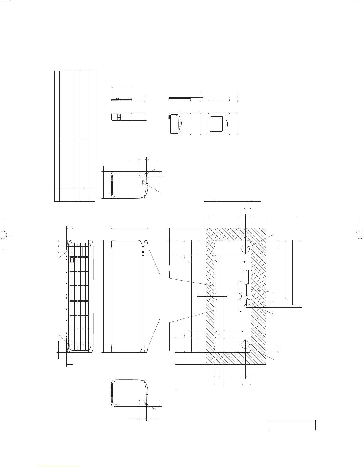
2. EXTERIOR DIMENSIONS
(1) Indoor units
Models SRK20ZSX-S, 25ZSX-S, 35ZSX-S, 50ZSX-S, 60ZSX-S
167
19
Unit:mm
SRK 20,25,35 φ9.52(3/8")(Flare)
Content
Gas piping
A
Symbol
60 45
Wireless remote control
SRK 50,60 φ12.7(1/2")(Flare)
VP16
φ6.35(1/4")(Flare)
(φ65)
(φ65)
Liquid piping
Hole on wall for right rear piping
Hole on wall for left rear piping
Outlet for piping
Drain hose
220 3
B
55
F
ECD
60 24
59.512.5
305
(Option)
Wired remote control
FF
45
Terminal block
100
118.5118.5 683
(Service space)
Unit
□120
10.3277.317.4
65120
(Service space)
□120 19
Notes(1)The model name label is attached
on the right side of the unit.
(2)To connect the wired remote control,
the interface kit(SC-BIKN-E) is required.
56.4
47
(Service space)
533
548
SRK 50,60 486
SRK 20,25,35 480
920
F F
6035
55
Outlet for downward piping
61
59.512.5
(Refer to the top view)
145 630 145
Installation board
100
(Service space)
-
-
8
176 568 176
460 460
48.6
88.6
Space for installation and service when viewing from the front
65 70
D B AE C
47
76.6
RLF000Z201
'17 • SRK-T-203
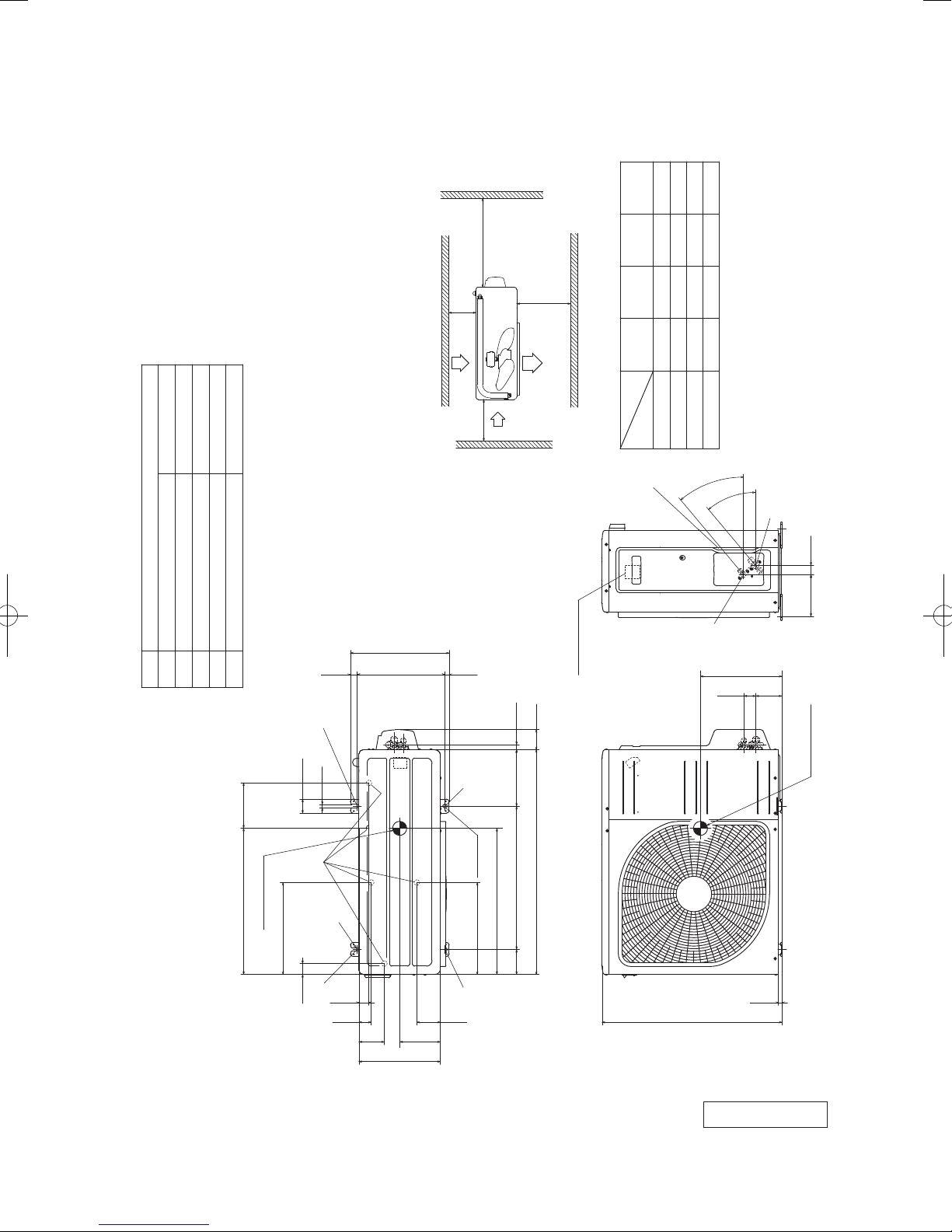
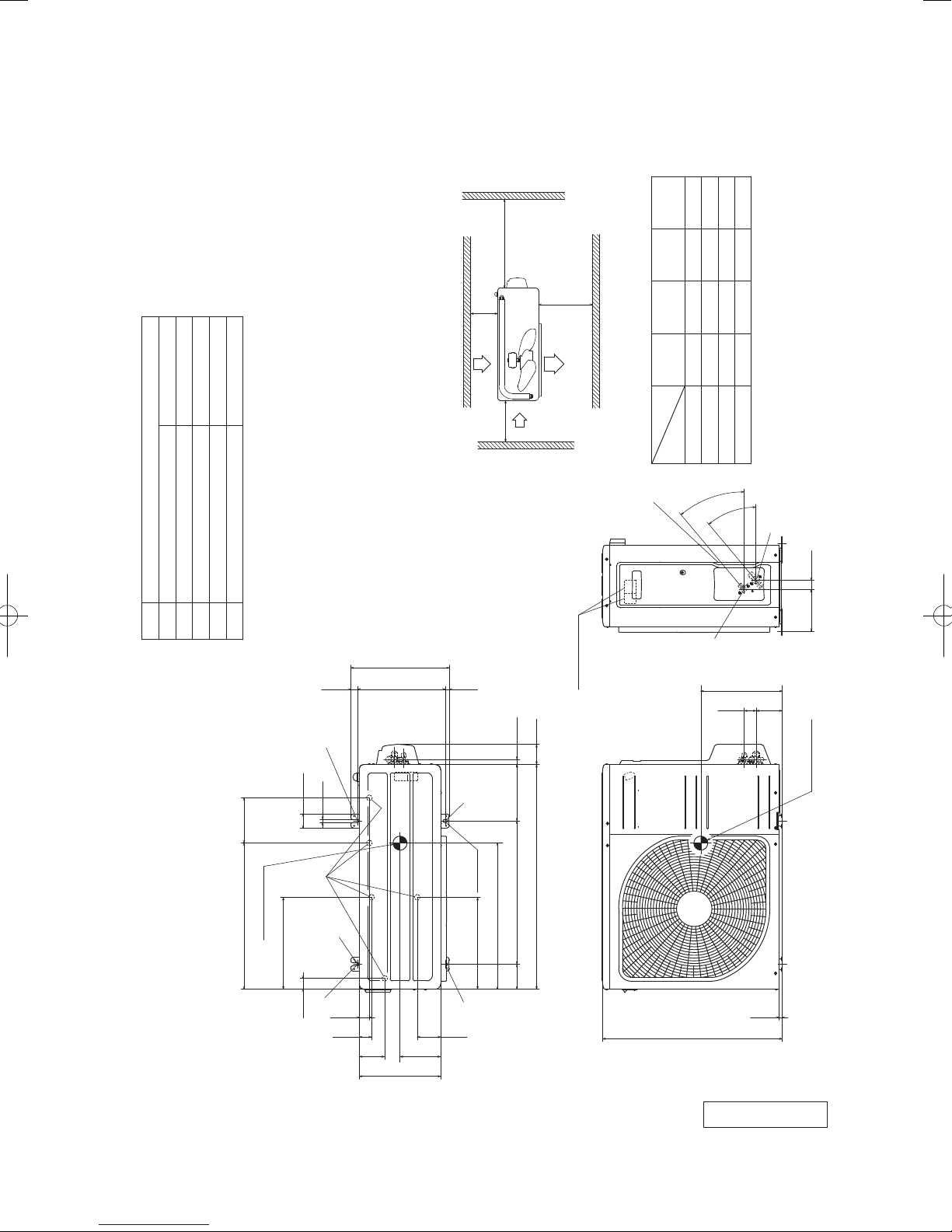
(2) Outdoor units
Models SRC20ZSX-S, 25ZSX-S, 35ZSX-S
φ9.52(3/8")( Flare)
Content
A Service valve connection(Gas side)
Symbol
M10-12×4 places
φ20×5 places
φ6.35(1/4")( Flare)
Drain discharge hole
Service valve connection(Liquid side)
E Anchor bolt hole
D
B
C Pipe/cable draw-out hole
L4
Service
space
( )
Inlet
17.9
L1
Outlet
71.2
L3
Inlet
L2
Notes
( 1) The unit must not be surrounded by walls on the four sides.
( 2) The unit must be fixed with anchor bolts. An anchor bolt must not
protrude more than 15mm.
( 3) If the unit is installed in the location where there is a possibility of
strong winds, place the unit such that the direction of air from the
outlet gets perpendicular to the wind direction.
( 4) Leave 200mm or more space above the unit.
( 5) The wall height on the outlet side should be 1200mm or less.
( 6) The model name label is attached on the right side of the unit.
351.6
24.3312.514.8
Ⅳ
180
Ⅲ
280
280
I Ⅱ
Open
Minimum installation space
installation
L1
Examples
Size
C
Terminal block
Open
Open
75
100
L2
80
80
80
100
L3
40°
Open
Unit:mm
250
Open
250
L4
40°
A
33.5148.4
B
290
93 42.5
12
50.6
520.6 161
Center of gravity
327.3
38.6
E
D E
2-12X16
2-R
E
35.6
43.5
90.6
290
327.3
E
83.5
145
800
Slot hole
520
89 510 201
640
Center of gravity
12.4
RCT000Z019
-
-
9
'17 • SRK-T-203
Model SRC50ZSX-S, 60ZSX-S
φ12.7(1/2")(Flare)
Content
A Service valve connection(Gas side)
Symbol
M10-12×4 places
φ20×5 places
φ6.35(1/4")(Flare)
Service valve connection(Liquid side)
Drain discharge hole
E Anchor bolt hole
D
B
C Pipe/cable draw-out hole
L4
Service
space
( )
L3
Inlet
L2
Notes
(1) The unit must not be surrounded by walls on the four sides.
(2) The unit must be fixed with anchor bolts. An anchor bolt must not
protrude more than 15mm.
(3) If the unit is installed in the location where there is a possibility of
strong winds, place the unit such that the direction of air from the
outlet gets perpendicular to the wind direction.
(4) Leave 200mm or more space above the unit.
(5) The wall height on the outlet side should be 1200mm or less.
(6) The model name label is attached on the front side of the unit.
351.6
24.3312.514.8
E
17.9
L1
Outlet
Inlet
Terminal block
71.2
Ⅳ
Ⅲ
I Ⅱ
Minimum installation space
installation
Examples
Size
C
180
Open
280
Open
75
280
100
Open
L2
L1
40°
40°
80
80
80
100
L3
Open
250
Open
250
L4
B
290
Unit:mm
A
33.5148.4
93 42.5
12
50.6
520.6 161
Center of gravity
327.3
38.6
E
D
2-12X16
2-R
E
35.6
43.5
90.6
290
327.3
E
83.5
145
800
Slot hole
520
89 510 201
640
Center of gravity
12.4
RCT000Z020
-
-
10
'17 • SRK-T-203
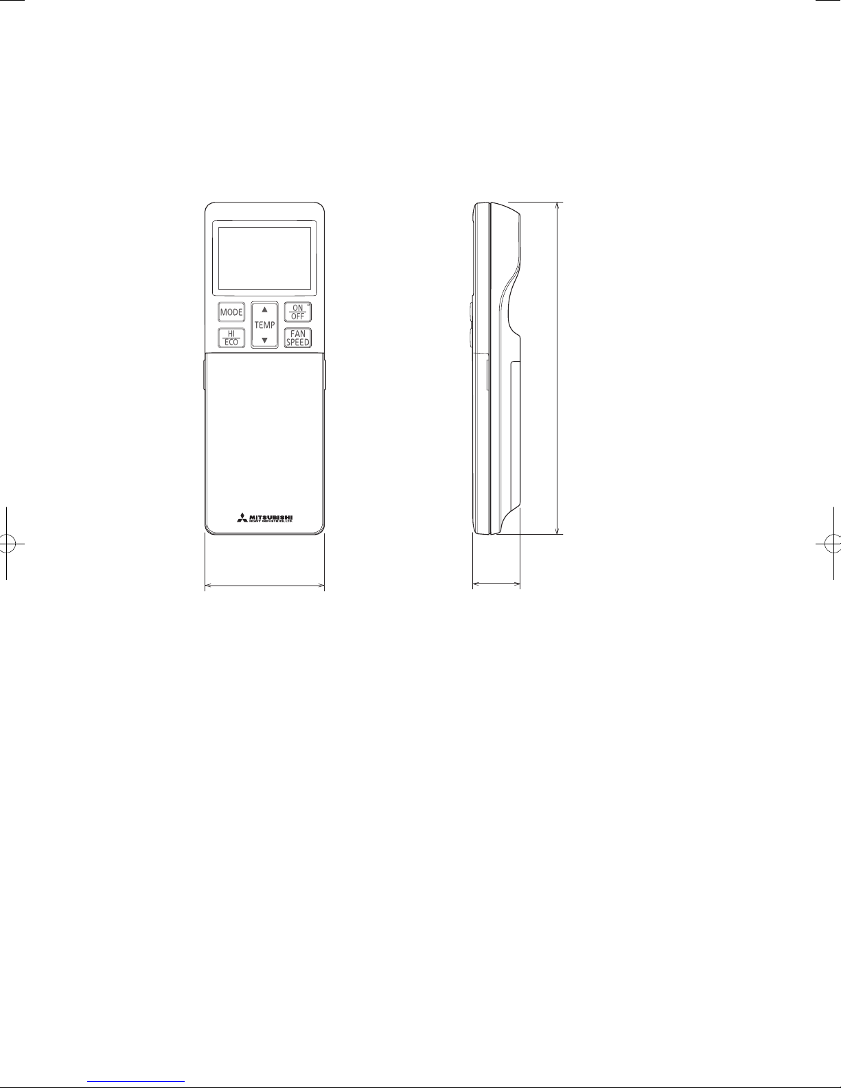
(3) Remote control
(3) Remote control
Wireless remote control
Unit : mm
167
60
26
-
11
-

'17 • SRK-T-203
(b) Wired remote control (option parts)
Interface kit (SC-BIKN-E) is required to use the wired remote control.
Wiring outlet
Cut off the upper thin part of remote control lower case with a nipper or knife,
Exposed mounting
0.3mm2×2 cores.
In case of pulling out
from upper left
L C D
48
In case of pulling out
from center
TEMP ON/OFF
and grind burrs with a file etc.
In case of pulling out
from upper left
Upper
Board
X Y
In case of pulling out
from center
Lower case
Lower part
Sheath
Upper cace
Upper part
Upper
Sheath
Upper cace
Board
YX
X, Y Terminal block
Attach M3 screw
□120
with washer
Pearl whiteExterior appearance
(Munsell color) (N8.5) near equivalent
Embedded mounting
Wall surface
Wiring
Electrical box
(Not included)
19
Remote
control
outline
Wiring oulet
12×7 Slot hole
Lower
In case of pulling out from
The peeling-off length of sheath
Pulling out from upper left
X wiring : 215mm
Y wiring : 195mm
Wiring
upper left
Pulling out from center
X wiring : 170mm
Y wiring : 190mm
Remote control installation dimensions
83.5
120
46
23
44
42
11.5 11
Installation hole
9.5×5 Slot hole (4 places)
Tighten the screws after
cutting off the thin part of
screw mounting part.
120
45
(1) Installation screw for remote control
M4 screw (2 pieces)
Lower
In case of pulling out from center
Wiring
The peeling-off length
of sheath
Unit:mm
Wiring specifications
(1) If the prolongation is over 100m, change to the size below.
But, wiring in the remote control case should be under 0.5mm
the case according to wire connecting. Waterproof treatment is necessary at the wire connecting
section. Be careful about contact failure.
Length Wiring thickness
100 to 200m
Under 300m
Under 400m
Under 600m
0.5mm
0.75mm
1.25mm
2.0mm
2
×2 cores
2
×2 cores
2
×2 cores
2
×2 cores
-
12
2
. Change the wire size outside of
-
PJZ000Z295
'17 • SRK-T-203
3. ELECTRICAL WIRING
(1) Indoor units
Models SRK20ZSX-S, 25ZSX-S, 35ZSX-S, 50ZSX-S, 60ZSX-S
ConnectorCNE
DescriptionItem
CNF
CNG
CNJ
CNL
CNM
CNP
CNS
CNU
CNX
CNY
CNZ
LEFT
MOTOR
LOUVER
M
RIGHT
MOTOR
LOUVER
M
FLAP
MOTOR
M
LEFT
FLAP
LOWER
RIGHT
LOWER
MOTOR
M
FLAP
UPPER
MOTOR
M
INLET
MOTOR
M
LEFT
INLET
MOTOR
M
INLET
RIGHT
SW
LIMIT
PANEL
FAN
MOTOR
M
N
2
1
3
5
DISPLAY
5
CNL
BOARD
CIRCUIT
PRINTED
CNE
7
BACK-UP SW
WIRELESS RECEIVER
5
CNZ
CNX
DIODE
STACK
t
SENSOR
ROOM TEMP.
5
CNG
t
SENSOR 1
HEAT EXCHANGER
5
CNY
CNM
CNF
2
t
HUMIDITY
SENSOR 2
HEAT EXCHANGER
5
CNJ
3
MOTION
SENSOR
5
CNP
CNS
5
INTERFACE KIT
SENSOR
G2
YELLOW/GREEN
RED
WHITE
BLACK
345
1
CNU
FUSE
U
VARISTOR
S/N
WHITE
HEAT
BLUE
YELLOW
6
250V
3.15A
J
L
RED
BLACK
EXCHANGER
Power source
YELLOW/GREEN
N
2
1 3
T
BLOCK
TERMINAL
POWER WIRES
SIGNAL WIRE
EARTH WIRE
[ ]
220V 60Hz
1 Phase
TO OUTDOOR UNIT
220-240V 50Hz
4
HEAT
EXCHANGER
-
13
RWA000Z412
-
'17 • SRK-T-203
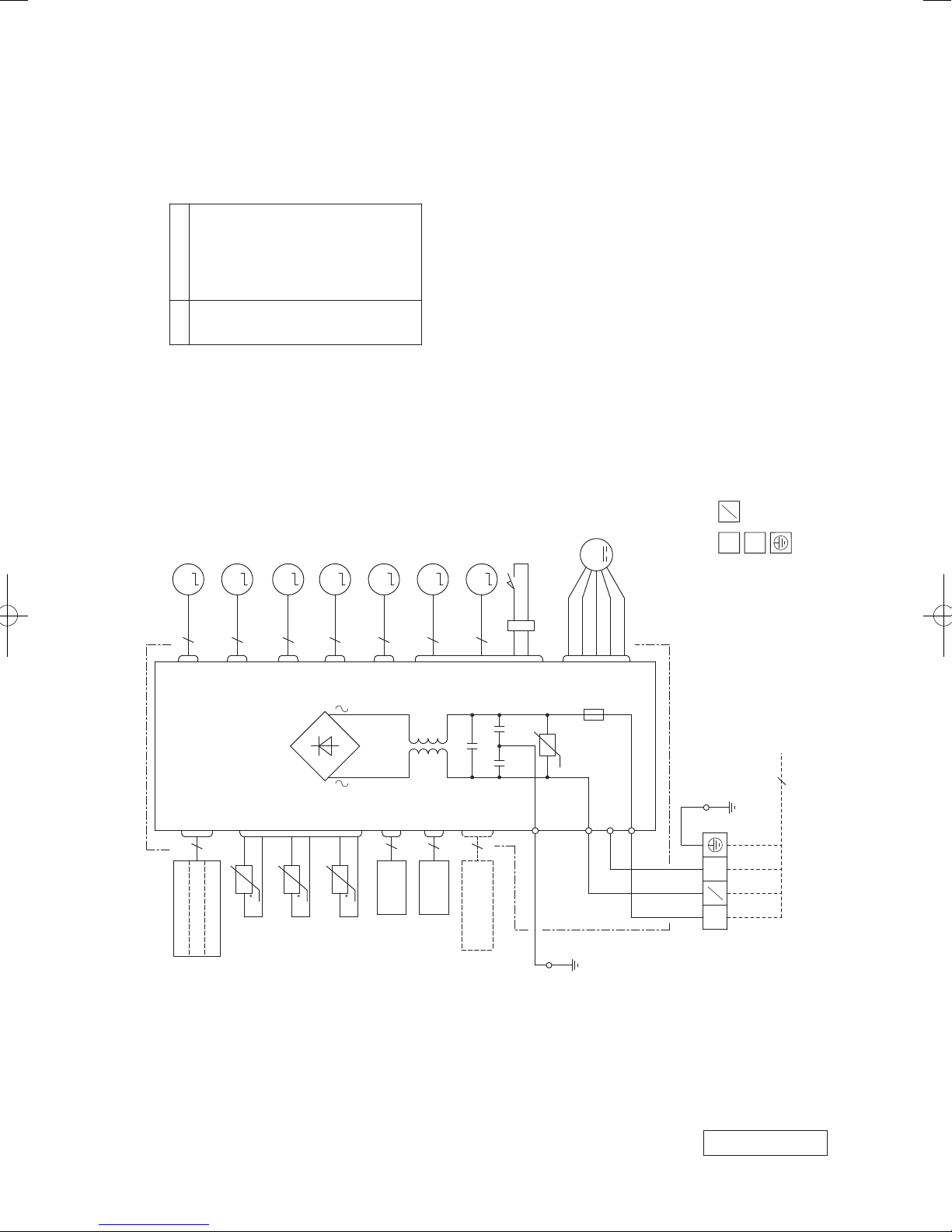
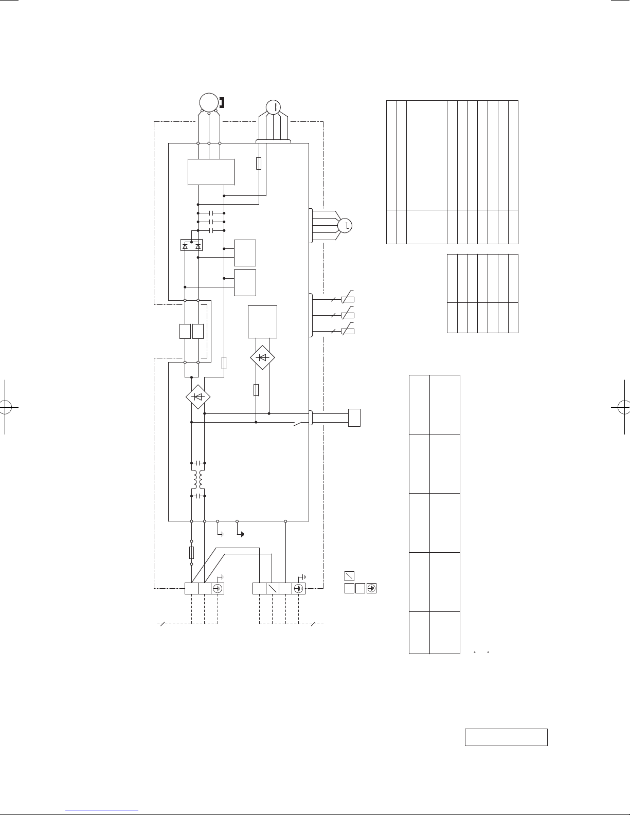
(2) Outdoor units
Models SRC20ZSX-S, 25ZSX-S, 35ZSX-S
CM
MS
3~
(BK)
(WH)
(RD)
U
V
W
UP
V
W
POWER
TRANSISTOR
PCB ASSY PCB1
F2
N
250V 20A
F3
T 1A L 250V
M
(WH)
CNFAN
FMo
+
+
+
DIODE
STACK2
~
L
T1 T2
(YE) (OR)
t゜
NOISE
FILTER
R.IN
(BK)
F7
250V 15A
-
~
PAM
CIRCUIT
F4
250V 10A
+
STACK1
~
+
STACK4
~
F1
C-2
(RD)
-
~
POWER
CIRCUIT
SWITCHING
-
~
t゜
F 3.15A L 250V
G1
(YG)
G2
(YG)
DIODE
DIODE
S.IN
(WH)
(RD)
(WH)
(BK)
CNTH CNEEV
CN20S
M
EEV
t゜
22
TH4TH2 TH3
t゜
t゜
2 2
20S
Item Description
CNEEV
CN20S Connector
20S 4 way valve(coil)
Meaning of marks
Connecting cable
wire size x number*
(m)
Power cable length
wire size x number*(A)
EEV Electric expansion valve(coil)
CM Compressor motor
CNTH
CNFAN
Mark Color
BK Black
Color marks
x 4
2
x 3 22 1.5mm
2
TH4 Discharge pipe temp. sensor
TH3 Outdoor air temp. sensor
TH2 Heat exchanger sensor
L Reactor
FMo Fan motor
Yellow/Green
RD Red
WH White
OR Orange
YE Yellow
YG
3
220V 60Hz
Power source
1 Phase
220-240V 50Hz
TB1
BLOCK
TERMINAL
(BK)
(YG)
3
L 1
N 2
4
]
N
2
1
3
POWER WIRES
SIGNAL WIRE
EARTH WIRE
TO INDOOR UNIT
[
9
MAX running current Power cable
Model name
Power cable, indoor-outdoor connecting wires
SRC20ZSX-S
Switchgear or circuit breaker capacity should be chosen according to national or regional electricity
The power cable specifications are based on the assumption that a metal or plastic conduit is used
with no more than three cables contained in a conduit and a voltage drop is 2%. For an installation
SRC35ZSX-S
SRC25ZSX-S 2.0mm
The wire numbers include earth wire(Yellow/Green)*regulations.
falling outside of these conditions, please follow the national or regional electricity regulations.
RWC000Z297
-
-
14
'17 • SRK-T-203
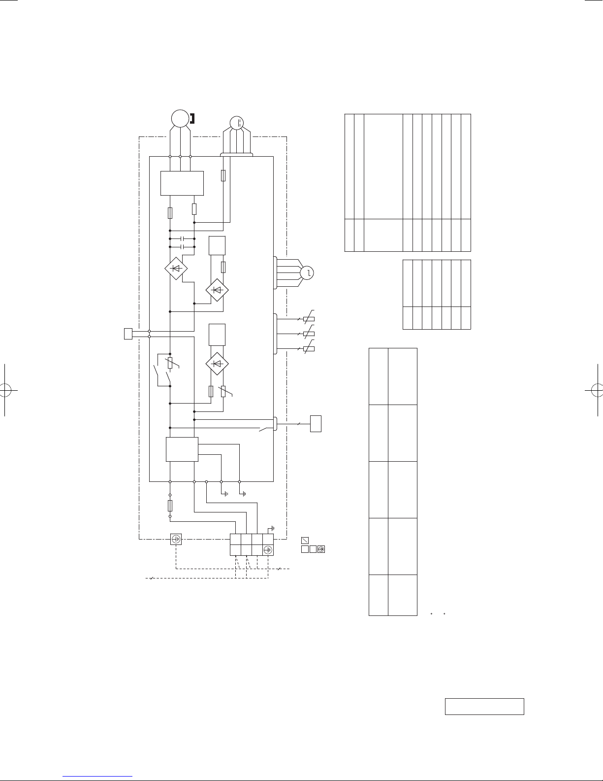
Models SRC50ZSX-S, 60ZSX-S
(RD)
UP
POWER
TRANSISTOR
MS
(WH)
VWU
CM
3~
(BK)
V
W
N
F3
T 1A L 250V
M
(WH)
CNFAN
FMo
+
++
T2
T12
(BL)
(YE)
L1
L2
(BL)
(YE)
T1
T11
+
-
DIODE
STACK1
~
~
PCB ASSY PCB1
F8
PAM
PAM
DIODE
250V 20A
CIRCUIT
CIRCUIT
SWITCHING
+
STACK2
~
F1
POWER
CIRCUIT
-
~
F 3.15A L 250V
(RD)
(WH)
(BK)
CNTH CNEEV
CN20S
M
EEV
Item Description
20S Solenoid coil for 4 way valve
CNFAN
CNEEV
CN20S Connector
EEV Electric expansion valve(coil)
CM Compressor motor
CNTH
TH3 Discharge pipe temp. sensor
TH2 Outdoor air temp. sensor
TH1 Heat exchanger sensor
L1,2 Reactor
FMo Fan motor
Meaning of marks
t゜
t゜
t゜
2 2 2
TH1 TH2 TH3
20S
Connecting cable
Power cable length
Color
BK Black
Mark
Color marks
x 4
2
wire size x number*
(m)
BL Blue
RD Red
YE Yellow
WH White
Yellow/Green
YG
S.IN
R.IN
(BK)
(WH)
F4
250V 20A
(BK)
N
L
TB1
BLOCK 1
TERMINAL
3
220V 60Hz
220-240V 50Hz
Power source
1 Phase
wire size x number*(A)
MAX running current Power cable
Model name
SRC50ZSX-S
x 3 13 1.5mm
2
2.0mm
15
SRC60ZSX-S
Switchgear or circuit breaker capacity should be chosen according to national or regional electricity
The power cable specifications are based on the assumption that a metal or plastic conduit is used
with no more than three cables contained in a conduit and a voltage drop is 2%. For an installation
The wire numbers include earth wire(Yellow/Green)*regulations.
falling outside of these conditions, please follow the national or regional electricity regulations.
G1
G2
(YG)
(YG)
(WH)
(YG)
BLOCK 2
TERMINAL
(BK)
TB2
C-2
(RD)
]
N
N
1
2
(YG)
3
4
2
3
1
POWER WIRES
SIGNAL WIRE
EARTH WIRE
TO INDOOR UNIT
Power cable, indoor-outdoor connecting wires
[
RWC000Z298
-
-
15
'17 • SRK-T-203
Mid octave band frequency (Hz)
N50
N30
N40
N60
N2
Mid octave band frequency (Hz)
N50
N40
N20
N30
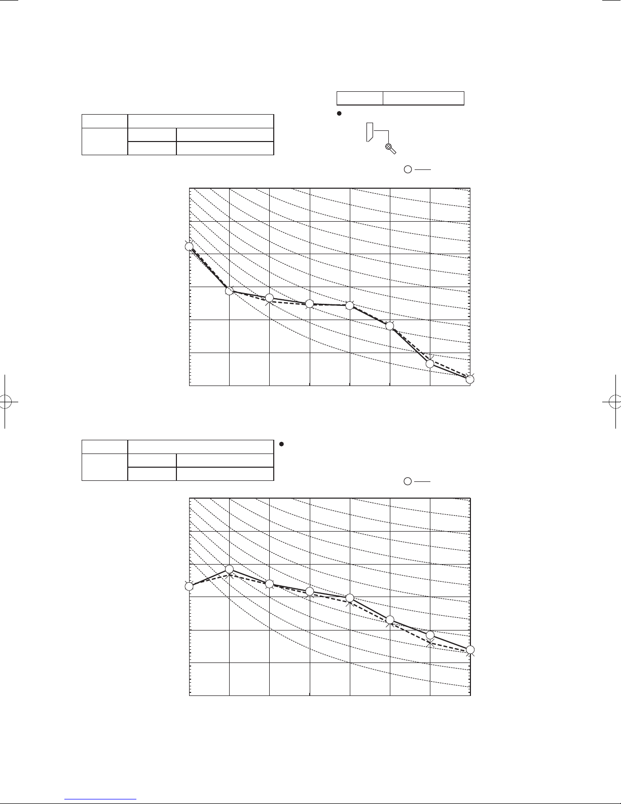
Mike position: at highest noise level in position as mentioned below
Mike position
0.8m
1m
Unit
Mike position
(Center & Low points)
Mike position
4. NOISE LEVEL
Model SRK20ZSX-S
(Indoor Unit)
Model SRK20ZSX-S
Noise
Level
Cooling 38 dB(A)
Heating 38 dB(A)
Condition ISO5151 T1/H1
1m
0.8m
×
......
Unit
Cooling,
Mike position
(Center & Low points)
Heating
70
60
50
Pa)
-5
40
(Standard 2×10
30
Sound pressure level (dB)
20
10
63 125 250 500 1000 2000 4000 8000
(Outdoor Unit)
Model SRC20ZSX-S
Noise
Level
Cooling 43 dB(A)
Heating 44 dB(A)
70
Distance from front side 1m
......
×
Cooling, Heating
70
N70
60
50
40
30
20
0
10
70
N70
60
50
Pa)
-5
40
(Standard 2×10
30
Sound pressure level (dB)
20
10
63 125 250 500 1000 2000 4000 8000
-
16
60
N60
50
40
30
20
10
-
'17 • SRK-T-203
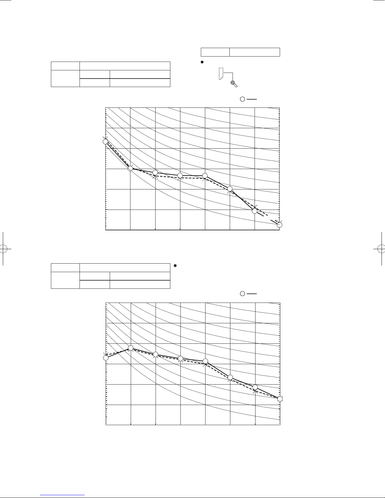
Model SRK25ZSX-S
Mid octave band frequency (Hz)
Mid octave band frequency (Hz)
Mike position: at highest noise level in position as mentioned below
Mike position
0.8m
1m
Unit
Mike position
(Center & Low points)
Mike position
(Indoor Unit)
Model SRK25ZSX-S
Noise
Level
Cooling 39 dB(A)
Heating 40 dB(A)
70
Condition ISO5151 T1/H1
1m
0.8m
×
......
Unit
Cooling,
Mike position
(Center & Low points)
Heating
70
N70
60
50
Pa)
-5
40
(Standard 2×10
30
Sound pressure level (dB)
20
10
63 125 250 500 1000 2000 4000 8000
(Outdoor Unit)
Model SRC25ZSX-S
Noise
Level
Cooling 44 dB(A)
Heating 45 dB(A)
70
Distance from front side 1m
......
×
Cooling, Heating
60
N60
50
N50
40
N40
30
N30
20
N20
10
70
N70
60
50
Pa)
-5
40
(Standard 2×10
30
Sound pressure level (dB)
20
10
63 125 250 500 1000 2000 4000 8000
-
17
60
N60
50
N50
40
N40
30
N30
20
N20
10
-
'17 • SRK-T-203
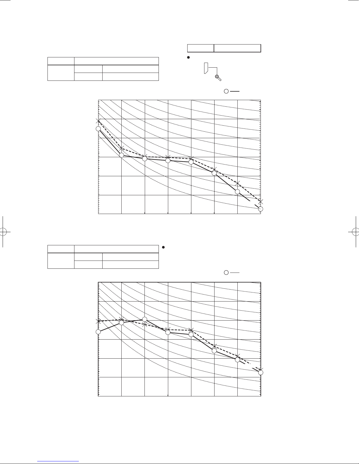
Model SRK35ZSX-S
Mid octave band frequency (Hz)
Mike position: at highest noise level in position as mentioned below
Mike position
0.8m
1m
Unit
Mike position
(Center & Low points)
Mike position
(Indoor Unit)
Model SRK35ZSX-S
Noise
Level
Cooling 43 dB(A)
Heating 41 dB(A)
70
Condition ISO5151 T1/H1
1m
0.8m
×
......
Unit
Cooling,
Mike position
(Center & Low points)
Heating
70
N70
60
50
Pa)
-5
40
(Standard 2×10
30
Sound pressure level (dB)
20
10
63 125 250 500 1000 2000 4000 8000
(Outdoor Unit)
Model SRC35ZSX-S
Noise
Level
Cooling 48 dB(A)
Heating 47 dB(A)
70
Distance from front side 1m
......
×
Cooling,
60
N60
50
N50
40
N40
30
N30
20
N20
10
Heating
70
N70
60
50
Pa)
-5
40
(Standard 2×10
30
Sound pressure level (dB)
20
10
63 125 250 500 1000 2000 4000 8000
Mid octave band frequency (Hz)
-
18
60
N60
50
N50
40
N40
30
N30
20
N20
-
'17 • SRK-T-203
Mike position
Model SRK50ZSX-S
Mike position: at highest noise level in position as mentioned below
Mike position
0.8m
1m
Unit
Mike position
(Center & Low points)
(Indoor Unit)
Model SRK50ZSX-S
Noise
Level
Cooling 44 dB(A)
Heating 46 dB(A)
70
Condition ISO5151 T1/H1
1m
0.8m
×
......
Unit
Cooling,
Mike position
(Center & Low points)
Heating
70
N70
60
50
Pa)
-5
40
(Standard 2×10
30
Sound pressure level (dB)
20
10
63 125 250 500 1000 2000 4000 8000
(Outdoor Unit)
Model SRC50ZSX-S
Noise
Level
Cooling 50 dB(A)
Heating 49 dB(A)
70
Mid octave band frequency (Hz)
Distance from front side 1m
......
×
Cooling,
60
N60
50
N50
40
N40
30
N30
20
N20
10
Heating
70
N70
60
50
Pa)
-5
40
(Standard 2×10
30
Sound pressure level (dB)
20
10
63 125 250 500 1000 2000 4000 8000
Mid octave band frequency (Hz)
-
19
60
N60
50
N50
40
N40
30
N30
20
N20
10
-
'17 • SRK-T-203
Model SRK60ZSX-S
Mid octave band frequency (Hz)
Mid octave band frequency (Hz)
Mike position: at highest noise level in position as mentioned below
Mike position
0.8m
1m
Unit
Mike position
(Center & Low points)
Mike position
(Indoor Unit)
Model SRK60ZSX-S
Noise
Level
Cooling 46 dB(A)
Heating 46 dB(A)
70
Condition ISO5151 T1/H1
1m
0.8m
×
......
Unit
Cooling,
Mike position
(Center & Low points)
Heating
N70
70
60
50
Pa)
-5
40
(Standard 2×10
30
Sound pressure level (dB)
20
10
63 125 250 500 1000 2000 4000 8000
(Outdoor Unit)
Model SRC60ZSX-S
Noise
Level
Cooling 52 dB(A)
Heating 52 dB(A)
70
Distance from front side 1m
......
×
Cooling,
60
N60
50
N50
40
N40
30
N30
20
N20
10
Heating
70
N70
60
50
Pa)
-5
40
(Standard 2×10
30
Sound pressure level (dB)
20
10
63 125 250 500 1000 2000 4000 8000
-
20
60
N60
50
N50
40
N40
30
N30
20
N20
10
-

'17 • SRK-T-203
5. PIPING SYSTEM
Models SRK20ZSX-S, 25ZSX-S, 35ZSX-S
Indoor unit
Room temp.
sensor
(Th1)
Humidity
sensor
(Th3)
Flare
connection
Heat
exchanger
sensor
(Th2
2)
Heat
exchanger
Heat
exchanger
sensor
1)
(Th2
Gas pipe
(φ9.52)
Liquid
pipe
(φ6.35)
Outdoor unit
Service valve
Gas
)
(
Muffler
Check joint
4-way valve
Service valve
(Liquid)
Discharge pipe
temp. sensor
(TH3)
Muffler
Compressor
Electronic
expansion valve
(EEV)
Capillary tube
Cooling cycle
Heating cycle
Accumulator
Capillary tube
Muffler
Outdoor air
temp. sensor
(TH2)
Heat
exchanger
Heat
exchanger
sensor
(TH1)
Flare connection
Models SRK50ZSX-S,60ZSX-S
Indoor unit
Room temp.
sensor
(Th1)
Humidity
sensor
(Th3)
Flare
connection
Heat
exchanger
sensor
(Th2
2)
Heat
exchanger
Heat
exchanger
sensor
1)
(Th2
Gas pipe
(φ12.7)
Liquid
pipe
(φ6.35)
Service valve
Strainer Muffler
Outdoor unit
Gas
)
(
Muffler
Check joint
4-way valve
Service valve
(Liquid)
Muffler
Receiver
Discharge pipe
temp. sensor
(TH3)
Compressor
Electronic
expansion valve
Capillary tube
(EEV)
Cooling cycle
Heating cycle
Accumulator
Capillary tube
Outdoor air
temp. sensor
(TH2)
Heat
exchanger
Heat
exchanger
sensor
(TH1)
Flare connection
Strainer
-
21
Muffler
-
'17 • SRK-T-203
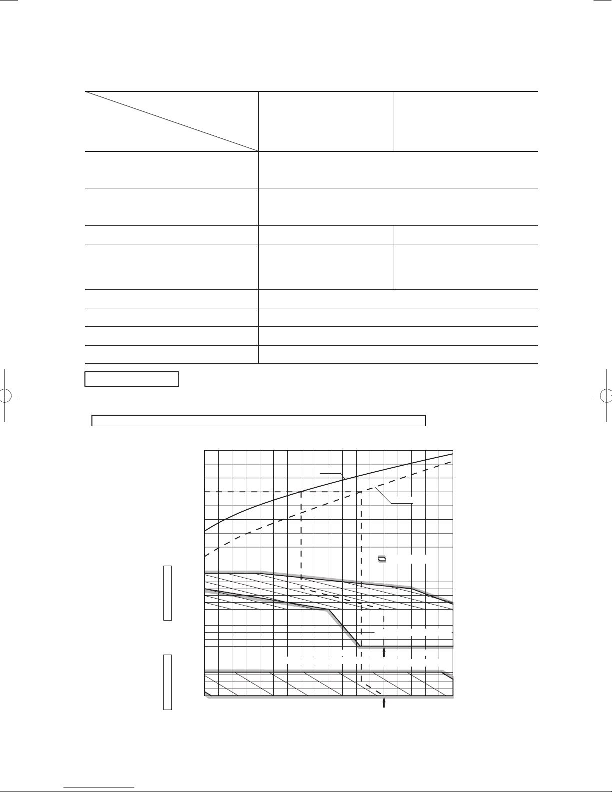
6. RANGE OF USAGE & LIMITATIONS
RANGE OF USAGE & LIMITATIONS
Models
SRK20, 25, 35ZSX-S
SRK50, 60ZSX-S
Item
Indoor return air temperature
(Upper, lower limits)
Outdoor air temperature
(Upper, lower limits)
Refrigerant line (one way) length
Vertical height difference between
outdoor unit and indoor unit
Cooling operation : Approximately 18 to 32℃ D.B.
Heating operation : Approximately 10 to 30℃ D.B.
(Refer to the selection chart)
Cooling operation : Approximately -15 to 46℃ D.B.
Heating operation : Approximately -20 to 24℃ D.B.
(Refer to the selection chart)
Max. 25m Max. 30m
Max. 15m
(Outdoor unit is higher)
Max. 15m
(Outdoor unit is lower)
(Outdoor unit is lower)
Max. 20m
(Outdoor unit is higher)
Max. 20m
Power source voltage Rating ±10%
Voltage at starting Min. 85% of rating
Frequency of ON-OFF cycle
Max. 4 times/h
(Inching prevention 10 minutes)
ON and OFF interval Min. 3 minutes
Selection chart
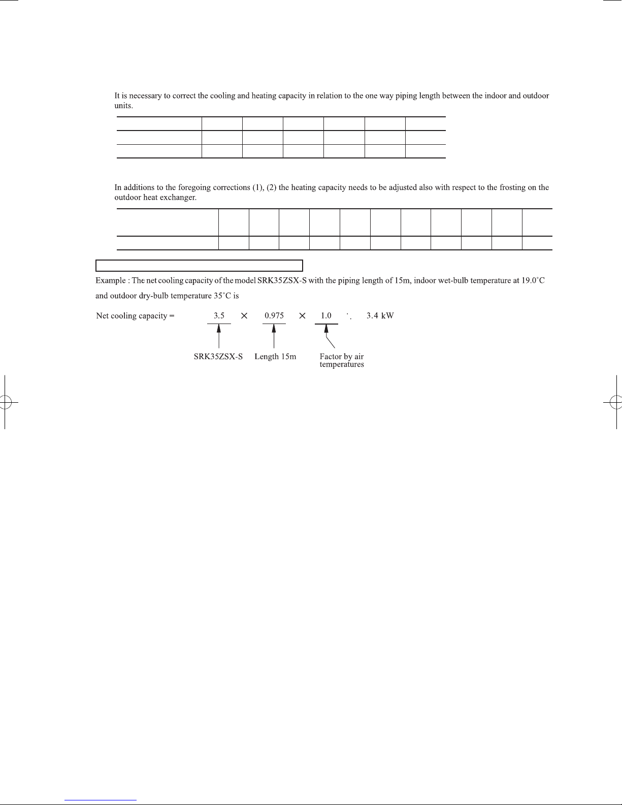
Correct the cooling and heating capacity in accordance with the conditions as follows. The net cooling and heating capacity can be
obtained in the following way.
Net capacity = Capacity shown on specification ×Correction factors as follows.
(1) Coefficient of cooling and heating capacity in relation to temperatures
1.3
&
1.2
1.1
1.0
0.9
0.8
Coefficient of cooling
Heating capacity in
relation to temperature
0.7
0.6
46
40
35
30
°C D. B.
25
temperature
20
Outdoor air D.B.
Cooling operation
0
-5
-10
-15
27
25
20
15
°C D. B.
10
temperature
Indoor air D.B.
Heating operation
Indoor air W.B. temperature °C W.B
-15-20 -10 -5 0 5 10 15
Cooling
Depends on installed situation
.
ISO-T1 Standard Condition
Outdoor air W.B. temperature °C W.B.
ISO-T1 Standard Condition
Heating
Applicable range
26
24
2220181614
-
22
-
'17 • SRK-T-203
'09•SRK-DB-087D
(2) Correction of cooling and heating capacity in relation to one way length of refrigerant piping
Piping length [m]
Cooling
Heating
(3) Correction relative to frosting on outdoor heat exchanger during heating
Air inlet temperature of
outdoor unit in °C WB
Adjustment coefficient
How to obtain the cooling and heating capacity
7
1.0
1.0
-20
0.95 1.00
10
0.99
1.0
-15
0.95 0.95
-10
15
0.975
1.0
20
0.965
1.0
0.94-90.93-70.91-50.88-30.86
=
25
0.95
1.0
30
0.935
1.0
-1 1
0.8730.92
5 or more
-
23
-
'17 • SRK-T-203
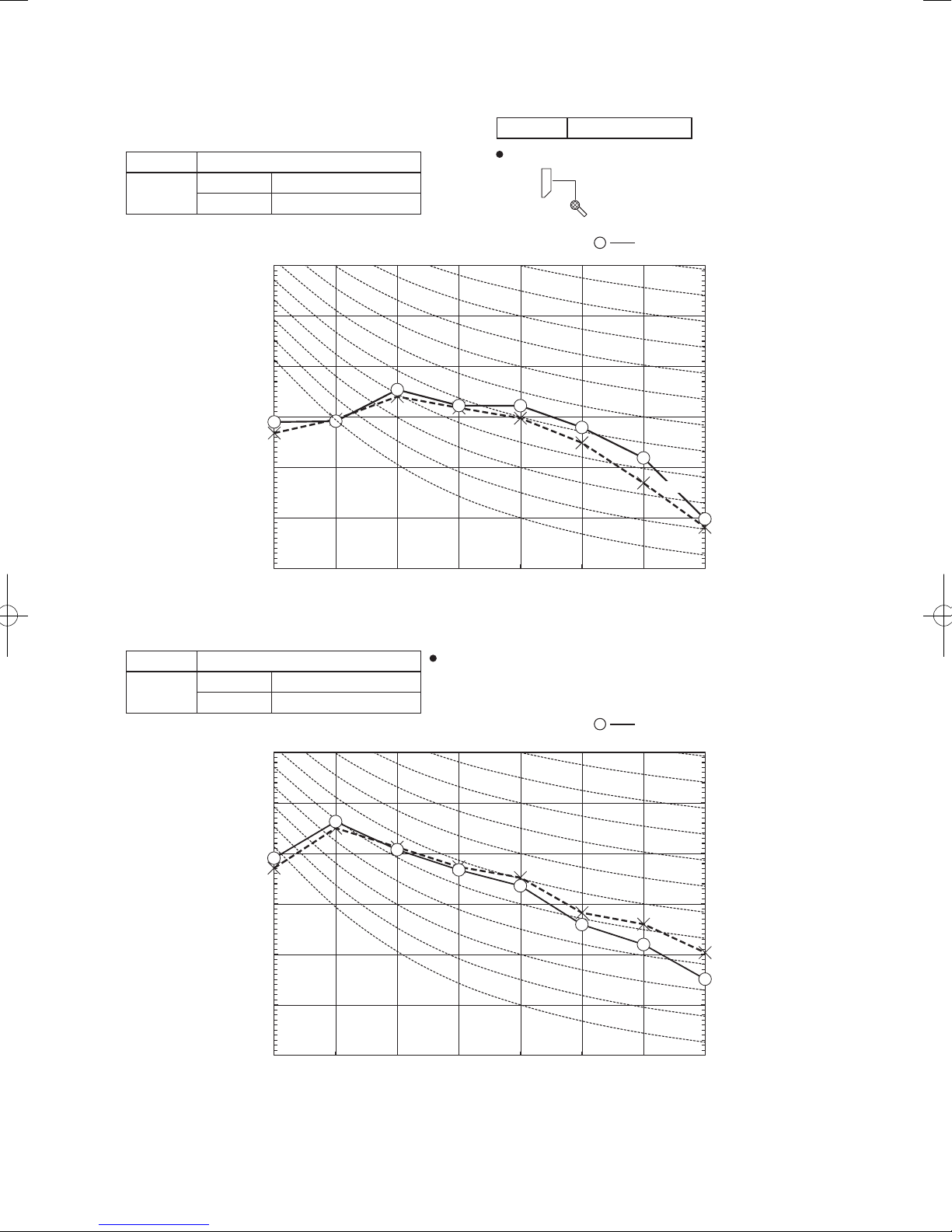
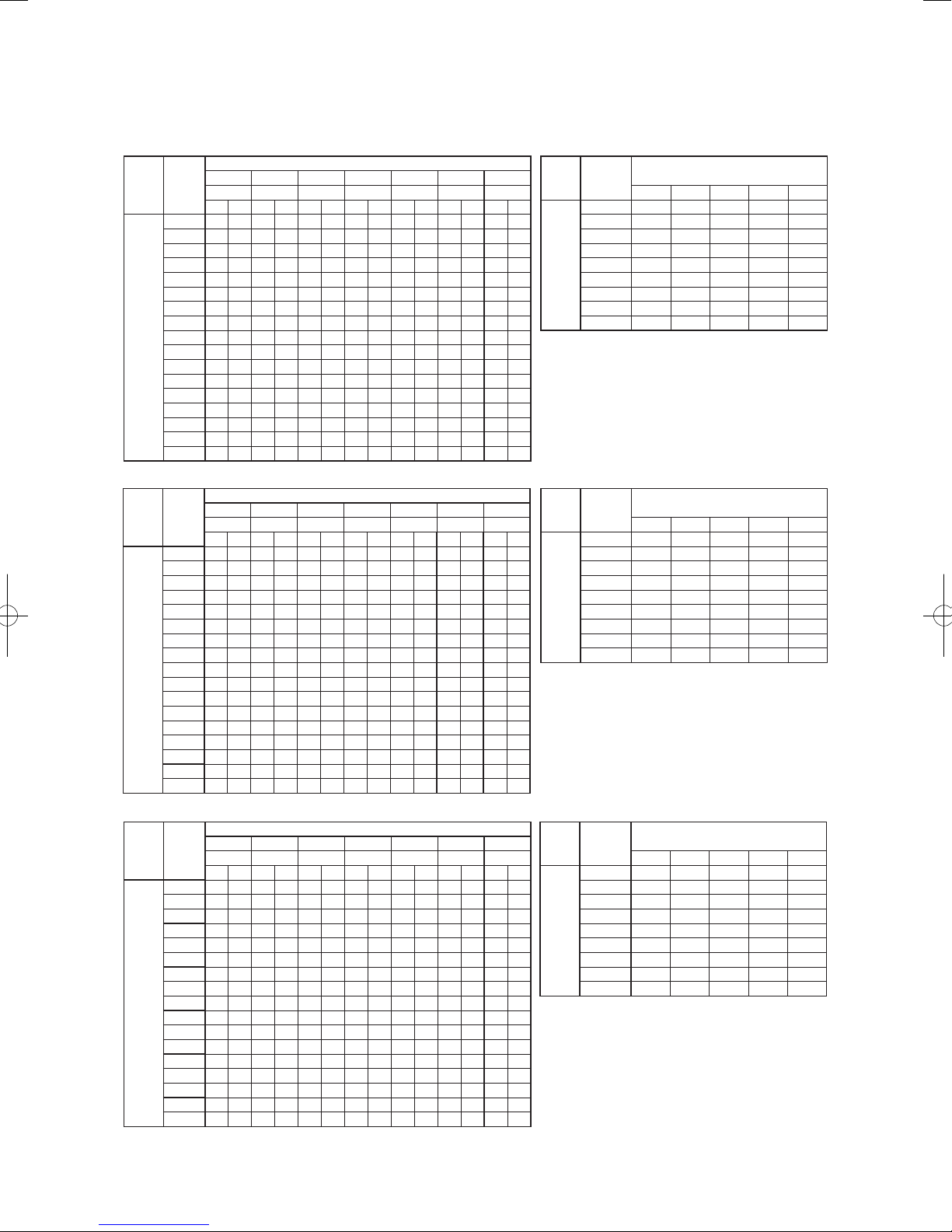
7. CAPACITY TABLES
Model SRK20ZSX-S
Outdoor
Air flow
air temp.
10 2.25 2.12 2.36 2.09 2.45 2.19 2.49 2.17 2.53 2.14 2.60 2.26 2.67 2.21
12 2.21 2.10 2.32 2.07 2.41 2.18 2.45 2.16 2.50 2.14 2.58 2.26 2.65 2.20
14 2.17 2.06 2.28 2.05 2.38 2.17 2.42 2.15 2.47 2.12 2.55 2.24 2.62 2.20
16 2.13 2.02 2.24 2.03 2.34 2.15 2.39 2.13 2.43 2.11 2.52 2.23 2.59 2.17
18 2.08 1.98 2.19 2.01 2.30 2.14 2.35 2.12 2.40 2.10 2.49 2.22 2.56 2.16
20 2.04 1.94 2.15 2.00 2.26 2.13 2.31 2.11 2.36 2.09 2.45 2.20 2.53 2.15
22 1.99 1.89 2.10 1.97 2.22 2.11 2.28 2.10 2.32 2.08 2.42 2.19 2.50 2.14
24 1.94 1.85 2.05 1.95 2.18 2.07 2.24 2.09 2.28 2.07 2.38 2.18 2.47 2.14
Hi
11.3
26 1.90 1.80 2.01 1.91 2.14 2.03 2.20 2.07 2.24 2.05 2.35 2.17 2.43 2.13
3
/min)
(m
28 1.85 1.75 1.96 1.86 2.09 1.99 2.15 2.05 2.20 2.04 2.31 2.16 2.40 2.12
30 1.79 1.70 1.90 1.81 2.05 1.94 2.11 2.01 2.16 2.02 2.27 2.15 2.36 2.11
32 1.74 1.65 1.85 1.76 2.00 1.90 2.07 1.96 2.12 2.00 2.23 2.12 2.32 2.10
34 1.69 1.60 1.80 1.71 1.95 1.85 2.02 1.92 2.07 1.97 2.19 2.08 2.28 2.09
35 1.66 1.58 1.77 1.68 1.93 1.83 2.00 1.90 2.05 1.94 2.17 2.06 2.26 2.08
36 1.63 1.55 1.74 1.65 1.90 1.81 1.98 1.88 2.02 1.92 2.15 2.04 2.24 2.08
38 1.58 1.50 1.68 1.60 1.85 1.76 1.93 1.83 1.98 1.88 2.11 2.00 2.20 2.07
39 1.55 1.47 1.66 1.57 1.83 1.74 1.91 1.81 1.95 1.85 2.08 1.98 2.18 2.06
Model SRK25ZSX-S
Outdoor
Air flow
air temp.
10 2.82 2.64 2.95 2.60 3.06 2.75 3.11 2.72 3.16 2.70 3.26 2.83 3.34 2.76
12 2.77 2.62 2.90 2.58 3.01 2.74 3.07 2.71 3.12 2.68 3.22 2.82 3.31 2.73
14 2.71 2.58 2.85 2.56 2.97 2.71 3.03 2.69 3.08 2.66 3.18 2.80 3.28 2.72
16 2.66 2.53 2.80 2.54 2.92 2.70 2.98 2.67 3.04 2.65 3.15 2.79 3.24 2.71
18 2.60 2.47 2.74 2.52 2.88 2.68 2.94 2.66 2.99 2.63 3.11 2.76 3.20 2.70
20 2.55 2.42 2.68 2.49 2.83 2.66 2.89 2.64 2.95 2.62 3.07 2.75 3.17 2.69
22 2.49 2.37 2.63 2.47 2.78 2.64 2.84 2.62 2.90 2.60 3.02 2.73 3.13 2.68
24 2.43 2.31 2.57 2.44 2.72 2.59 2.80 2.60 2.85 2.58 2.98 2.72 3.08 2.67
Hi
12.2
26 2.37 2.25 2.51 2.38 2.67 2.54 2.74 2.59 2.80 2.56 2.93 2.71 3.04 2.66
3
/min)
(m
28 2.31 2.19 2.44 2.32 2.61 2.48 2.69 2.56 2.75 2.55 2.89 2.69 3.00 2.64
30 2.24 2.13 2.38 2.26 2.56 2.43 2.64 2.51 2.70 2.53 2.84 2.68 2.95 2.63
32 2.18 2.07 2.31 2.20 2.50 2.37 2.58 2.46 2.64 2.51 2.79 2.65 2.90 2.62
34 2.11 2.00 2.25 2.13 2.44 2.32 2.53 2.40 2.59 2.46 2.74 2.60 2.85 2.61
35 2.08 1.97 2.21 2.10 2.41 2.29 2.50 2.38 2.56 2.43 2.71 2.58 2.83 2.60
36 2.04 1.94 2.18 2.07 2.38 2.26 2.47 2.35 2.53 2.40 2.69 2.55 2.80 2.59
38 1.97 1.87 2.11 2.00 2.32 2.20 2.41 2.29 2.47 2.35 2.63 2.50 2.75 2.58
39 1.94 1.84 2.07 1.97 2.28 2.17 2.38 2.26 2.44 2.32 2.61 2.48 2.72 2.57
Cooling Mode
Indoor air temp
21˚CDB 23˚CDB 26˚CDB 27˚CDB 28˚CDB 31˚CDB 33˚CDB
14˚CWB 16˚CWB 18˚CWB 19˚CWB 20˚CWB 22˚CWB 24˚CWB
TC SHC TC SHC TC SHC TC SHC TC SHC TC SHC TC SHC
Cooling Mode
Indoor air temp
21˚CDB 23˚CDB 26˚CDB 27˚CDB 28˚CDB 31˚CDB 33˚CDB
14˚CWB 16˚CWB 18˚CWB 19˚CWB 20˚CWB 22˚CWB 24˚CWB
TC SHC TC SHC TC SHC TC SHC TC SHC TC SHC TC SHC
Heating Mode (HC) (kW)(kW)
outdoor
Air flow
air temp.
16˚CDB 18˚CDB 20˚CDB 22˚CDB 24˚CDB
-15˚CWB 1.66 1.63 1.59 1.55 1.52
-10˚CWB 1.88 1.85 1.82 1.78 1.74
-5˚CWB 2.04 2.01 1.97 1.94 1.91
0˚CWB 2.13 2.10 2.07 2.04 2.01
Hi
12.2
(m
Air flow
12.8
(m
5˚CWB 2.72 2.69 2.67 2.62 2.58
3
/min)
6˚CWB 2.76 2.73 2.70 2.67 2.63
10˚CWB 2.94 2.91 2.89 2.85 2.82
15˚CWB 3.20 3.17 3.14 3.11 3.08
20˚CWB 3.43 3.41 3.39 3.35 3.32
Heating Mode (HC) (kW)(kW)
outdoor
air temp.
16˚CDB 18˚CDB 20˚CDB 22˚CDB 24˚CDB
-15˚CWB 1.97 1.93 1.88 1.84 1.80
-10˚CWB 2.23 2.19 2.16 2.10 2.06
-5˚CWB 2.41 2.38 2.33 2.30 2.27
0˚CWB 2.53 2.49 2.45 2.42 2.38
Hi
5˚CWB 3.22 3.19 3.17 3.10 3.06
3
/min)
6˚CWB 3.27 3.24 3.20 3.16 3.12
10˚CWB 3.48 3.45 3.42 3.38 3.34
15˚CWB 3.79 3.75 3.73 3.69 3.65
20˚CWB 4.07 4.04 4.02 3.97 3.94
indoor air temp
indoor air temp
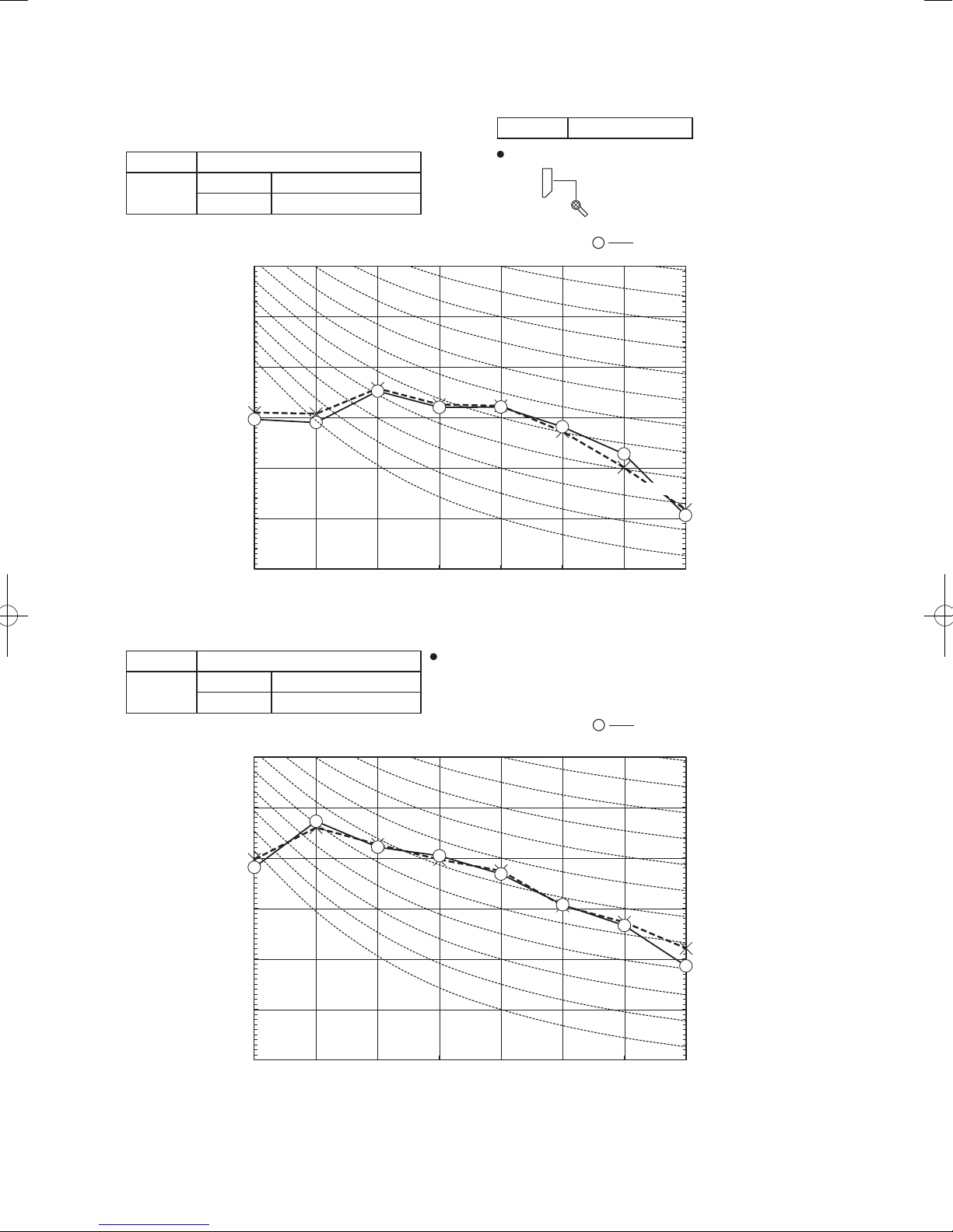
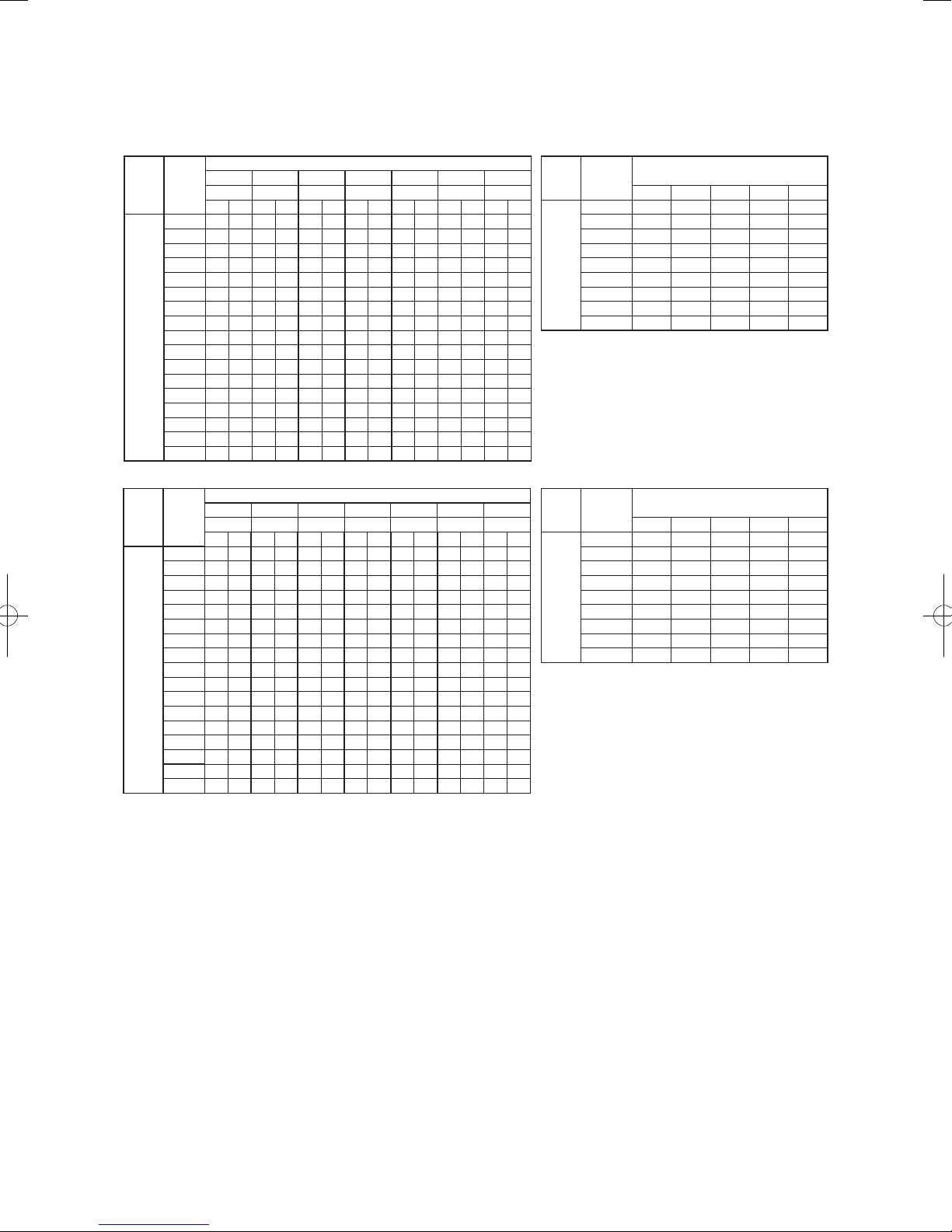
Model SRK35ZSX-S
Outdoor
Air flow
air temp.
10 3.94 3.46 4.13 3.40 4.28 3.57 4.35 3.53 4.43 3.49 4.56 3.64 4.68 3.55
12 3.87 3.42 4.06 3.37 4.22 3.55 4.29 3.51 4.37 3.47 4.51 3.62 4.63 3.53
14 3.80 3.39 3.99 3.34 4.16 3.52 4.24 3.49 4.31 3.45 4.46 3.61 4.59 3.52
16 3.72 3.36 3.91 3.31 4.09 3.50 4.18 3.46 4.25 3.43 4.40 3.59 4.54 3.50
18 3.65 3.32 3.84 3.28 4.03 3.47 4.11 3.44 4.19 3.40 4.35 3.57 4.49 3.49
20 3.57 3.28 3.76 3.24 3.96 3.44 4.05 3.41 4.13 3.38 4.29 3.55 4.43 3.47
22 3.49 3.24 3.68 3.20 3.89 3.42 3.98 3.39 4.06 3.36 4.23 3.53 4.38 3.46
24 3.40 3.20 3.59 3.17 3.81 3.39 3.91 3.36 3.99 3.33 4.17 3.51 4.32 3.44
Hi
13.1
26 3.32 3.15 3.51 3.13 3.74 3.35 3.84 3.34 3.92 3.31 4.11 3.49 4.26 3.42
3
/min)
(m
28 3.23 3.07 3.42 3.10 3.66 3.32 3.77 3.30 3.85 3.28 4.04 3.47 4.20 3.40
30 3.14 2.98 3.33 3.06 3.58 3.29 3.70 3.28 3.78 3.25 3.98 3.44 4.13 3.37
32 3.05 2.90 3.24 3.02 3.50 3.26 3.62 3.25 3.70 3.22 3.91 3.42 4.06 3.36
34 2.95 2.81 3.14 2.98 3.41 3.23 3.54 3.22 3.62 3.19 3.84 3.39 4.00 3.33
35 2.91 2.76 3.10 2.94 3.37 3.20 3.50 3.20 3.58 3.18 3.80 3.38 3.96 3.32
36 2.86 2.72 3.05 2.90 3.33 3.16 3.46 3.19 3.54 3.17 3.76 3.37 3.92 3.31
38 2.76 2.62 2.95 2.80 3.24 3.08 3.38 3.16 3.46 3.14 3.69 3.35 3.85 3.29
39 2.71 2.57 2.90 2.75 3.20 3.04 3.33 3.15 3.42 3.12 3.65 3.34 3.81 3.28
Cooling Mode
21˚CDB 23˚CDB 26˚CDB 27˚CDB 28˚CDB 31˚CDB 33˚CDB
14˚CWB 16˚CWB 18˚CWB 19˚CWB 20˚CWB 22˚CWB 24˚CWB
TC SHC TC SHC TC SHC TC SHC TC SHC TC SHC TC SHC
Indoor air temp
-
24
Heating Mode (HC) (kW)(kW)
outdoor
Air flow
air temp.
16˚CDB 18˚CDB 20˚CDB 22˚CDB 24˚CDB
-15˚CWB 2.65 2.59 2.53 2.48 2.42
-10˚CWB 2.99 2.94 2.90 2.83 2.77
-5˚CWB 3.24 3.20 3.13 3.10 3.05
0˚CWB 3.40 3.35 3.29 3.25 3.20
Hi
13.9
3/m
(m
Notes(1) These data show average statuses.
5˚CWB 4.33 4.28 4.26 4.17 4.11
in)
6˚CWB 4.40 4.35 4.30 4.25 4.19
10˚CWB 4.68 4.63 4.60 4.54 4.49
15˚CWB 5.09 5.04 5.01 4.95 4.91
20˚CWB 5.47 5.42 5.40 5.34 5.29
Depending on the system control, there may be ranges where the operation
is not conducted continuously.
These data show the case where the operation frequency of a compressor is
fixed.
(2) Capacities are based on the following conditions.
Corresponding refrigerant piping length :7m
Level difference of Zero.
(3) Symbols are as follows.
TC : Total cooling capacity (kW)
SHC : Sensible heat capacity (kW)
HC : Heating capacity (kW)
indoor air temp
-
'17 • SRK-T-203
Model SRK50ZSX-S
21˚CDB 23˚CDB 26˚CDB 27˚CDB 28˚CDB 31˚CDB 33˚CDB
Outdoor
Air flow
air temp.
14˚CWB 16˚CWB 18˚CWB 19˚CWB 20˚CWB 22˚CWB 24˚CWB
TC SHC TC SHC TC SHC TC SHC TC SHC TC SHC TC SHC
10 5.63 4.45 5.90 4.37 6.11 4.54 6.22 4.48 6.32 4.42 6.51 4.57 6.69 4.43
12 5.53 4.40 5.80 4.32 6.03 4.50 6.14 4.45 6.25 4.39 6.44 4.54 6.62 4.40
14 5.43 4.34 5.70 4.28 5.94 4.47 6.05 4.42 6.16 4.36 6.37 4.51 6.55 4.38
16 5.32 4.29 5.59 4.23 5.85 4.43 5.96 4.38 6.08 4.33 6.29 4.48 6.48 4.36
18 5.21 4.24 5.48 4.18 5.75 4.39 5.88 4.34 5.99 4.29 6.21 4.45 6.41 4.33
20 5.10 4.18 5.37 4.13 5.65 4.35 5.78 4.31 5.90 4.26 6.13 4.42 6.33 4.31
22 4.98 4.13 5.25 4.08 5.55 4.30 5.69 4.26 5.80 4.21 6.05 4.39 6.25 4.28
24 4.86 4.07 5.14 4.02 5.45 4.25 5.59 4.22 5.71 4.18 5.96 4.36 6.17 4.25
Hi
14.3
26 4.74 4.01 5.01 3.97 5.34 4.21 5.49 4.18 5.61 4.14 5.87 4.33 6.08 4.23
3
/min)
(m
28 4.61 3.95 4.89 3.91 5.23 4.16 5.39 4.14 5.50 4.10 5.78 4.30 5.99 4.20
30 4.49 3.89 4.76 3.86 5.11 4.12 5.28 4.10 5.40 4.06 5.68 4.26 5.90 4.17
32 4.35 3.82 4.63 3.80 5.00 4.07 5.17 4.05 5.29 4.02 5.58 4.22 5.81 4.13
34 4.22 3.76 4.49 3.74 4.88 4.01 5.06 4.01 5.18 3.98 5.48 4.19 5.71 4.10
35 4.15 3.73 4.42 3.70 4.82 3.99 5.00 3.99 5.12 3.95 5.43 4.17 5.66 4.08
36 4.08 3.70 4.35 3.67 4.76 3.96 4.94 3.96 5.06 3.93 5.37 4.15 5.61 4.07
38 3.94 3.63 4.21 3.61 4.63 3.91 4.82 3.91 4.94 3.88 5.27 4.11 5.50 4.04
39 3.87 3.60 4.14 3.58 4.57 3.89 4.76 3.89 4.88 3.86 5.21 4.09 5.45 4.02
Model SRK60ZSX-S
21˚CDB 23˚CDB 26˚CDB 27˚CDB 28˚CDB 31˚CDB 33˚CDB
Outdoor
Air flow
air temp.
14˚CWB 16˚CWB 18˚CWB 19˚CWB 20˚CWB 22˚CWB 24˚CWB
TC SHC TC SHC TC SHC TC SHC TC SHC TC SHC TC SHC
10 6.87 5.29 7.19 5.21 7.46 5.38 7.58 5.30 7.72 5.23 7.94 5.38 8.16 5.21
12 6.75 5.23 7.07 5.14 7.35 5.33 7.48 5.26 7.62 5.19 7.86 5.35 8.08 5.18
14 6.62 5.17 6.95 5.08 7.24 5.28 7.38 5.22 7.52 5.15 7.77 5.31 8.00 5.15
16 6.49 5.10 6.82 5.02 7.13 5.23 7.28 5.18 7.42 5.11 7.68 5.27 7.91 5.12
18 6.36 5.03 6.69 4.96 7.02 5.18 7.17 5.13 7.31 5.06 7.58 5.24 7.82 5.09
20 6.22 4.96 6.55 4.89 6.89 5.13 7.06 5.08 7.20 5.02 7.48 5.20 7.73 5.06
22 6.08 4.89 6.41 4.83 6.77 5.07 6.94 5.01 7.08 4.96 7.38 5.16 7.63 5.03
24 5.93 4.81 6.27 4.76 6.64 5.00 6.82 4.97 6.96 4.91 7.27 5.13 7.53 4.99
Hi
16.3
26 5.78 4.74 6.12 4.69 6.51 4.95 6.70 4.92 6.84 4.86 7.16 5.08 7.42 4.95
3
/min)
(m
28 5.63 4.66 5.96 4.62 6.38 4.89 6.57 4.86 6.71 4.82 7.05 5.04 7.31 4.92
30 5.47 4.59 5.81 4.55 6.24 4.83 6.44 4.81 6.58 4.76 6.93 5.00 7.20 4.88
32 5.31 4.51 5.65 4.48 6.10 4.78 6.31 4.76 6.45 4.71 6.81 4.95 7.08 4.85
34 5.15 4.43 5.48 4.40 5.95 4.72 6.17 4.71 6.31 4.66 6.68 4.91 6.96 4.81
35 5.07 4.39 5.40 4.36 5.88 4.69 6.10 4.68 6.24 4.63 6.62 4.89 6.90 4.78
36 4.98 4.35 5.31 4.32 5.80 4.65 6.03 4.65 6.17 4.61 6.56 4.86 6.84 4.76
38 4.81 4.27 5.14 4.25 5.65 4.59 5.89 4.59 6.03 4.55 6.42 4.81 6.71 4.72
39 4.72 4.23 5.05 4.21 5.57 4.56 5.81 4.57 5.95 4.53 6.36 4.79 6.65 4.70
Cooling Mode
Indoor air temp
Cooling Mode
Indoor air temp
Heating Mode (HC) (kW)(kW)
outdoor
Air flow
air temp.
16˚CDB 18˚CDB 20˚CDB 22˚CDB 24˚CDB
-15˚CWB 3.69 3.61 3.53 3.45 3.38
-10˚CWB 4.18 4.10 4.05 3.95 3.86
-5˚CWB 4.52 4.46 4.37 4.32 4.25
0˚CWB 4.74 4.67 4.59 4.54 4.47
Hi
17.3
(m
Air flow
17.8
(m
Notes(1) These data show average statuses.
5˚CWB 6.04 5.97 5.94 5.82 5.74
3
/min)
6˚CWB 6.14 6.07 6.00 5.92 5.85
10˚CWB 6.52 6.46 6.42 6.34 6.27
15˚CWB 7.10 7.04 6.99 6.91 6.85
20˚CWB 7.63 7.57 7.53 7.45 7.39
Heating Mode (HC) (kW)(kW)
outdoor
air temp.
16˚CDB 18˚CDB 20˚CDB 22˚CDB 24˚CDB
-15˚CWB 4.18 4.09 4.00 3.92 3.83
-10˚CWB 4.73 4.65 4.59 4.47 4.38
-5˚CWB 5.13 5.05 4.95 4.90 4.82
0˚CWB 5.38 5.30 5.20 5.14 5.07
Hi
5˚CWB 6.85 6.77 6.73 6.60 6.51
3
/min)
6˚CWB 6.96 6.88 6.80 6.71 6.63
10˚CWB 7.39 7.32 7.28 7.18 7.11
15˚CWB 8.05 7.98 7.92 7.83 7.76
20˚CWB 8.65 8.58 8.54 8.44 8.37
Depending on the system control, there may be ranges where the operation
is not conducted continuously.
These data show the case where the operation frequency of a compressor is
fixed.
(2) Capacities are based on the following conditions.
Corresponding refrigerant piping length :7m
Level difference of Zero.
(3) Symbols are as follows.
TC : Total cooling capacity (kW)
SHC : Sensible heat capacity (kW)
HC : Heating capacity (kW)
indoor air temp
indoor air temp
-
25
-
'17 • SRK-T-203
WARNING
CAUTION
WARNING
CAUTION
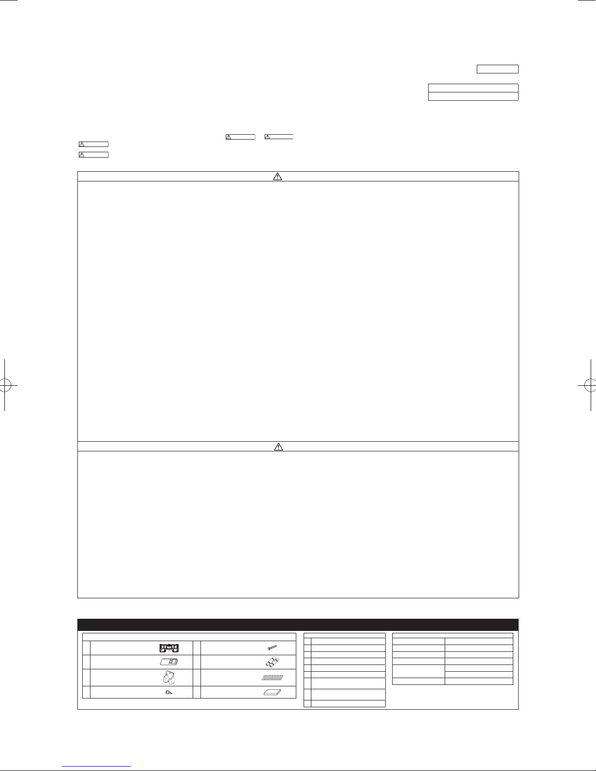
8. APPLICATION DATA
(1) Installation of indoor unit
•
This installation manual deals with an indoor unit installation only. For an outdoor unit installation, refer to page 30.
• Before installation, read the “SAFETY PRECAUTIONS” carefully and strictly follow it during the installation work in order to protect yourself.
•
The precautionary items mentioned below are distinguished into two levels,
Indicates a potentially hazardous situation which, if not avoided, can result in serious con-
sequences such as death or severe injury.
Indicates a potentially hazardous situation which, if not avoided, can result in personal inju-
Both mention the important items to protect your health and safety. Therefore, strictly follow them by any means.
• Be sure to use only for residential purpose.
If this unit is installed in inferior environment such as machine shop, vehicle (like ship), warehouse,
• Installationmustbe carriedoutbythequalied installercompletelyinaccor-
Installationbynon qualiedpersonorincorrect installationcancauseserious troublessuchaswater
•
Impropersafetymeasurescanresultinpersonalinjury.
• Usetheoriginalaccessoriesandthespeciedcomponentsfortheinstallation.
Usingpartsotherthanthoseprescribedmaycausewaterleak,electricshock,reandpersonalinjury.
•
Ifleaked gasesaccumulate around theunit, itcan causere resultingin propertydamage andper-
• When installing the unit in small rooms, make sure that refrigerant density
If refrigerant density exceeds the limit, consult the dealer and install the ventilation system.
Otherwise lack of oxygen can occur resulting in serious accident.
• Install the unit in a location where unit will remain stable, horizontal and free
Unsuitableinstallationlocationcancausetheunittofallresultinginmaterialdamageandpersonalinjury.
• Do not run the unit with removed panels or protections.
Touchingrotatingequipments, hot surfacesor highvoltage parts cancause personal injurydue to
• ThisunitisdesignedspecicallyforR410A.
Usinganyotherrefrigerantcancauseunitfailureandpersonalinjury.
• DonotventR410Aintoatmosphere.
R410AisauorinatedgreenhousegaswithaGlobalWarmingPotential(GWP)=2088.
• Make sure that no air enters the refrigerant circuit when the unit is installed
If air enters the refrigerant circuit, the pressure in the refrigerant circuit will become too high, which
• Besuretousetheprescribedpipes,arenutsandtoolsforR410A.
Usingexistingparts(forR22orR407C)can causerefrigerantcircuitburstresultinginunit failureand
• Be sure to connect both liquid and gas connecting pipes properly before op-
Do not open the liquid and gas service valves before completing piping work,
If the compressor is operated when connecting pipes are not connected and service valves are open,
• Besuretotightenthearenutstospeciedtorqueusingthetorquewrench.
Tighteningarenutswithexcesstorquecancauseburstandrefrigerantleakageafteralongperiod.
• Take care when carrying the unit by hand.
Iftheunitweightismorethan20kg,itmustbecarriedbytwoormorepersons.
Do not carry the unit by the plastic straps. Always use the carry handle.
• Do not install the outdoor unit in a location where insects and small animals
Insectsandsmallanimalscanentertheelectricalpartsandcause damageresultinginreorperson
• If the outdoor unit is installed at height, make sure that there is enough space
Insufcientspacecanresultinpersonalinjuryduetofallingfromtheheight.
• Do not install the unit near the location where neighbours are bothered by
It can affect surrounding environment and cause a claim.
• Do not install in the locations where unit is directly exposed to corrosive
It can cause corrosion of heat exchanger and damage to plastic parts.
• Do not install the unit close to the equipments that generate electromagnetic
Equipment such as inverters, standby generators, medical high frequency equipments and telecom-
The system can also affect medical equipment and telecommunication equipment, and obstruct its
ry or property damage.
etc., it can malfunction.
dance with the installation manual.
leak,electricshock,reandpersonalinjury.
Be sure to wear protective goggles and gloves while performing installation work.
Donotinstalltheunitnearthelocationwhereleakageofammablegasescanoccur.
sonalinjury.
does not exceed the limit (Reference: ISO5149) in the event of leakage.
of any vibration transmission.
entrapment, burn or electric shock.
and removed.
cancauseburstandpersonalinjury.
personalinjury.
erating the compressor.
and evacuation.
air can be sucked into the refrigerant circuit which can cause anomalous high pressure resulting in
burstorpersonalinjury.
can inhabit.
alinjury.Instructtheusertokeepthesurroundingsclean.
for installation, maintenance and service.
noise or air generating from the unit.
gases (like sulphide gas, chloride gas), sea breeze or salty atmosphere.
waves and/or high-harmonic waves.
munication equipments can affect the system, and cause malfunctions and breakdowns.
functionorcausejamming.
SAFETY PRECAUTIONS
and
•Be sureto conrmno operation problemon theequipment after completingthe installation. Ifunusual
noise can be heard during the test run, consult the dealer.
• Be sure to explain the operating methods as well as the maintenance methods of this equipment to the
.
user according to the user’s manual.
• Be sure to keep the installation manual together with user’s manual at a place where it is easily accessible to the user any time. Moreover, ask the user to hand the manuals to a new user, whenever required.
WARNING
• During pump down work, be sure to stop the compressor before closing ser
vice valves and removing connecting pipes.
If the connecting pipes are removed when the compressor is in operation and service valves are
open, air can be sucked into the refrigerant circuit which can cause anomalous high pressure result
inginburstorpersonalinjury.
• In the event of refrigerant leakage during installation, be sure to ventilate the
working area properly.
Iftherefrigerantcomesintocontactwithnakedames,poisonousgaseswillbeproduced.
• Electricalwork mustbe carriedoutbythequalied electrician,strictlyinac-
cordance with national or regional electricity regulations.
Incorrectinstallationcancauseelectricshock,reorpersonalinjury.
• Make sure that earth leakage breaker and circuit breaker of appropriate ca
pacities are installed.
Circuitbreaker should beable to disconnectall poles underover current.Absence ofappropriate
breakerscancauseelectricshock,personalinjuryorpropertydamage.
• Be sure to switch off the power source in the event of installation, mainte
nance or service.
Ifthepowersourceisnotswitchedoff,thereisariskofelectricshock,unitfailureorpersonalinjury.
• Be sure to tighten the cables securely in terminal block and relieve the ca-
bles properly to prevent overloading the terminal blocks.
Looseconnectionsorcablemountingscancauseanomalousheatproductionorre.
• Do not process, splice or modify the power cable, or share the socket with
other power plugs.
Improperpower cableorpower plugcancause reor electricshockdue topoorconnection, insuf
cient insulation or over-current.
• Do not perform any change in protective device or its setup condition yourself.
Changingprotectivedevicespecicationscancauseelectricshock,reorburst.
• Be sure to clamp the cables properly so that they do not touch any internal
component of the unit.
Ifcablestouchanyinternalcomponent,itcancauseoverheatingandre.
• Be sure to install service cover properly.
Improperinstallationcancauseelectricshockorreduetointrusionofdustorwater.
• Be sure to use the prescribed power and connecting cables for electrical work.
Usingimpropercablescancauseelectricleak,anomalousheatproductionorre.
• This appliance must be connected to main power source by means of a cir
cuit breaker or switch with a contact separation of at least 3mm.
Improperelectricalworkcancauseunitfailureorpersonalinjury.
•
Whenpluggingthisunit,aplugconformingtothenormIEC60884-1mustbeused.
Usingimproperplugcancauseelectricshockorre.
• Be sure to connect the power source cable with power source properly.
Improperconnectioncancauseintrusionofdustorwaterresultinginelectricshockorre.
CAUTION
• Do not install the unit in the locations where:
• There are heat sources nearby.
• Unit is directly exposed to rain or sunlight.
• There is any obstacle which can prevent smooth air circulation from inlet and outlet side of the unit.
• Unit is directly exposed to oil mist and steam such as kitchen.
•Chemical substances likeammonia (organic fertilizer),calcium chloride (snowmelting agent) and
acid (sulfurous acid etc.), which can harm the unit, will generate or accumulate.
• Drain water can not be discharged properly.
• TV set or radio receiver is placed within 1m.
• Height above sea level is more than 1000m.
Itcancauseperformancedegradation,corrosionanddamageofcomponents,unitmalfunctionandre.
• Dispose of all packing materials properly.
Packingmaterialscontainnailsandwoodwhichcancausepersonalinjury.
Keep the polybag away from children to avoid the risk of suffocation.
• Do not put anything on the outdoor unit.
Objectmayfallcausingpropertydamageorpersonalinjury.
• Donottouchthealuminumnoftheoutdoorunit.
Aluminiumntemperatureishighduringheatingoperation.Touchingncancauseburn.
•
Do not touch any refrigerant pipe with your hands when the system is in operation.
During operation the refrigerant pipes become extremely hot or extremely cold depending on the
operatingcondition.Touchingpipescancausepersonalinjurylikeburn(hot/cold).
• Install isolator or disconnect switch on the power source wiring in accor
dance with the local codes and regulations.
TheisolatorshouldbelockedinOFFstateinaccordancewithEN60204-1.
RLF012A200
ModelSRK20,25,35,50,60ZSX-S
R410AREFRIGERANTUSED
-
-
-
-
-
-
-
1. ACCESSORIES AND TOOLS
Standard accessories (supplied with indoor unit)
(1) Installation board
(2) Wireless remote control
(3) Remote control holder
Tapping screws
(4)
(for installation board ø4 X 25mm)
1pc (5)
1pc (6)
1pc (7) Air-cleaninglters 2pcs
4pcs (8) Insulation (#486 50 X 100 t3) 1pc
Wood screws
(for remote control holder ø3.5 X 16mm)
Batteries [R03 (AAA, Micro) 1.5V]
(a) Sleeve (1pc)
2pcs
(b) Sealing plate (1pc)
(c) Inclination plate (1pc)
(d) Putty
2pcs
(e) Connecting cable
(f) Drain hose (extension hose)
Piping cover
(g)
(for insulation of connection piping)
Clampandscrew(fornishing
(h)
work)
(i) Electrical tape
-
-
26
Locally procured parts
Plus headed driver Pipe cutter
Knife
Saw Wrench key (Hexagon) [4m/m]
Tape measure Flaring tool set*
Torque wrench
(14.0-62.0N·m (1.4-6.2kgf·m))
Plier Flare adjustment gauge
Tools for installation Work
Hole core drill (65mm in diameter)
Gas leak detector*
Pipe bender
*DesignedspecicallyforR410A
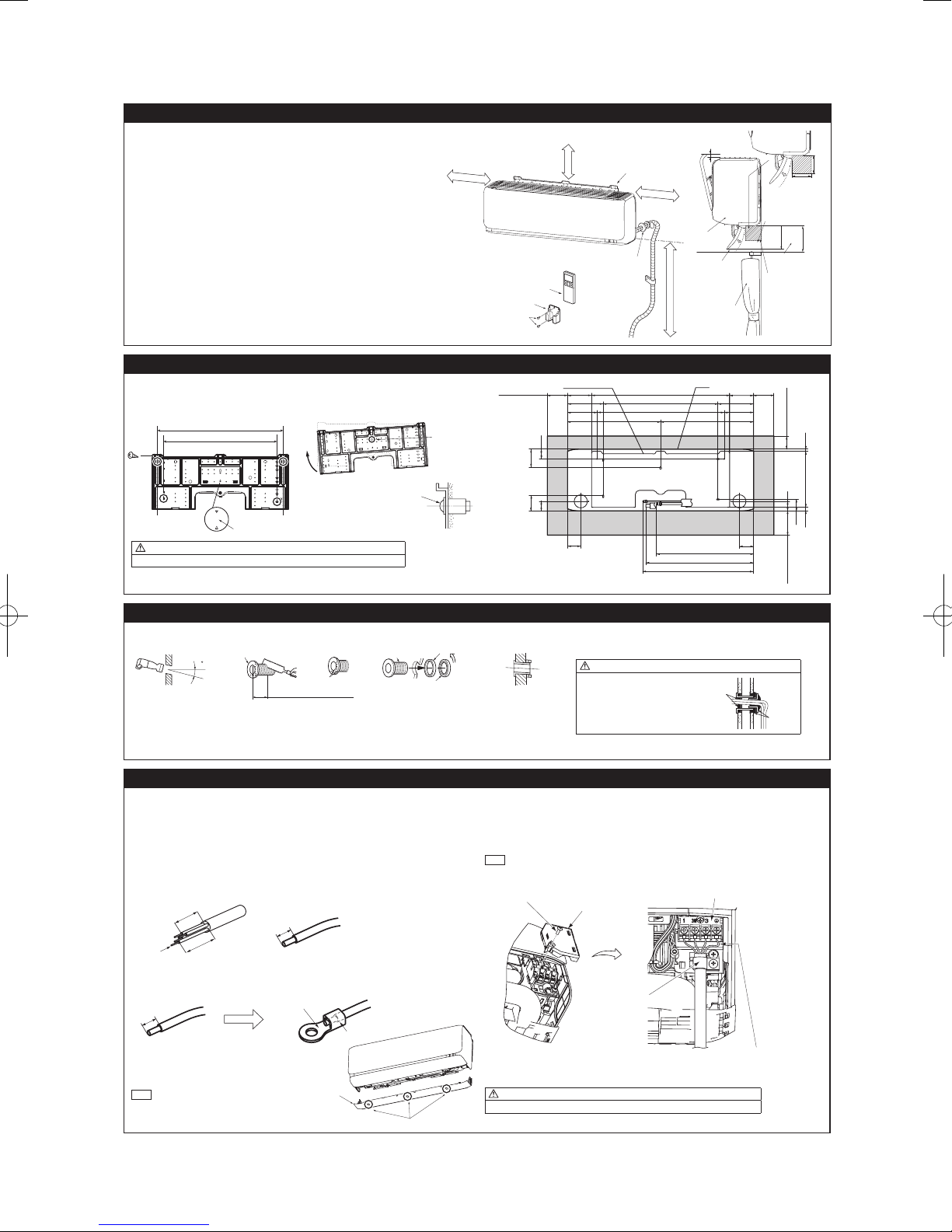
'17 • SRK-T-203
2.SELECTINGINSTALLATIONLOCATION
6.5 cm minimum from the ceiling
hole
630
Mating mark for level surface
277.317.4
Installation board
Unit
Indoor side Outdoor side
Indoor side Outdoor side Installed state
(c) Inclination plate
(d) Putty
(d) Putty
Earth wir
10mm
10mm
Round crimp-type terminal
The screw of the terminal
cover is tightened securely
Bottom panel
Screw (in the cap)
After getting customer’s approval, select installation location according to following guidelines.
1. Indoor unit
• Wherethereisnoobstructiontotheairowandwherethecooledandheatedaircanbe
evenly distributed.
• A solid place where the unit or the wall will not vibrate.
• A place where there will be enough space for servicing.
(Where space mentioned on the right side can be secured.)
• Where it is easy to conduct wiring and piping work.
• A place where unit is not directly exposed to sunlight or street light.
• A place where it can be easily drained.
• A place separated at least 1m away from the television or the radio.
(To prevent interference to images and sounds.)
• A place where this unit is not affected by the high frequency equipment or electric equipment.
• Avoid installing this unit in place where there is much oil mist.
• A place where there is no electric equipment or household.
• Installtheindoorunitonthewallwheretheheightfromtheoortothebottomoftheunitis
more than 180 cm.
2.Wirelessremotecontrol
• A place where the air-conditioner can receive the signal surely during operating the wireless
remote control.
• A place where it is not affected by the TV and radio etc.
• Do not place where it is exposed to direct sunlight or near heat devices such as a stove.
3. INSTALLING INSTALLATION BOARD
• Installation board should be installed on the wall which can support the weight of the indoor unit.
• Adjustment of the installation board in the horizontal direction is to be conducted with 4 screws in a
temporary tightened state.
• With the standard hole as a center, adjust the board and level it.
Bolt
(M6X12)
Standard
568
In case of fixing the unit on
concrete wall, use nut anchor.
CAUTION
Improper adjustment of the installation board can cause water leakage.
10 cm minimum
from the wall
Remote control holder
Wireless
remote control
Wood screws
(Service Space)
88.6
76.6
100
48.6
47
65
(In the case of less than 10 cm,
there is a possibility of performance
degradation.)
145 630
(a) Sleeve
460
Installation board
10 cm minimum
from the wall
568176
Installation example
2 cm
Indoor
unit
Be sure that the
flap of outlet
should not
touch any
obstacles.
Obstacle such
as curtain
180 cm minimum from the floor
100
118.5118.5 683
176
145
460
480 (Gas pipe)
533 (Drain hose)
548 (Liquid pipe)
70
Unit: mm
Maximum
moving range
11 cm 12 cm
Flap removal
position
Need to
secure a
space for
service
(Service Space)
65
47
120
7.9 cm
56.4
7.0
cm
10.3
4.DRILLINGHOLEANDFIXTUREOFSLEEVE
When drilling the wall that contains a metal lath, wire lath or metal plate, be sure to use sealing plate, sleeve and inclination plate (Locally procured parts).
5
ø65
(1) Drill a hole with hole
core drill.
(a) Sleeve
Top
Thickness of the wall + 1.5cm
(2) Cut sleeve to adjust to wall
thickness. In case of rear
piping draw out, cut off the
lower and the right side
portions of the sleeve collar.
Cut
(a) Sleeve
(3) Fix sealing plate, sleeve
and inclination plate.
(b) Sealing plate
Turn to
tighten
CAUTION
After passing the wirings and pipes
through the hole, completely seal
the hole on the wall with putty to
prevent water leakage.
5. ELECTRICAL WIRING WORK
• Beforeinstallation,makesurethatthepowersourcecomplieswiththeair-conditioner ’spowerspecication.
• Carry out electrical wiring work according to following guidelines.
1. Preparing cable
(1) Selecting cable
Selecttheconnectingcableinaccordancewiththespecicationsmentionedbelow.
4-core* 1.5mm
* 1 Earth wire is included (Yellow/Green).
(2) Arrange each wire length as shown below.
Make sure that each wire is stripped 10mm from the end.
2
conformed with 60245 IEC57 (CENELEC H05RN-F)
<Connecting cable> <Wire end>
30mm or more
40mm or more
e
(3) Attach round crimp-type terminal to each wire as shown in the below.
Selectthesizeofroundcrimp-typeterminalafterconsideringthespecicationsofterminalblock
and wire diameter.
2.Removebottompanel
(1) Remove the 3 screws (in the cap).
(2) Remove the hooks of left and right side
and then bottom panel can be removed.
NOTE
• Openthecapusingane-tippedtool.
• When opening the cap, exercise care not to
damage the design surface.
Sleeve
3. Connecting cable
(1) Remove the terminal cover.
(2) Remove the cable clamp.
(3) Connect the connecting wires to the terminal block.
(4) Fix the connecting cable by cable clamp.
(5) Fix the terminal cover.
NOTE
Take care not to confuse the terminal numbers for indoor and outdoor connections.
.
Terminal cover
Cable clamp
CAUTION
Incorrectwiringconnectioncancausemalfunctionorre.
Terminal block
• Earth wire shall be Yellow/Green (Y/G) in color and
longer than other wires for safety reason.
-
27
-
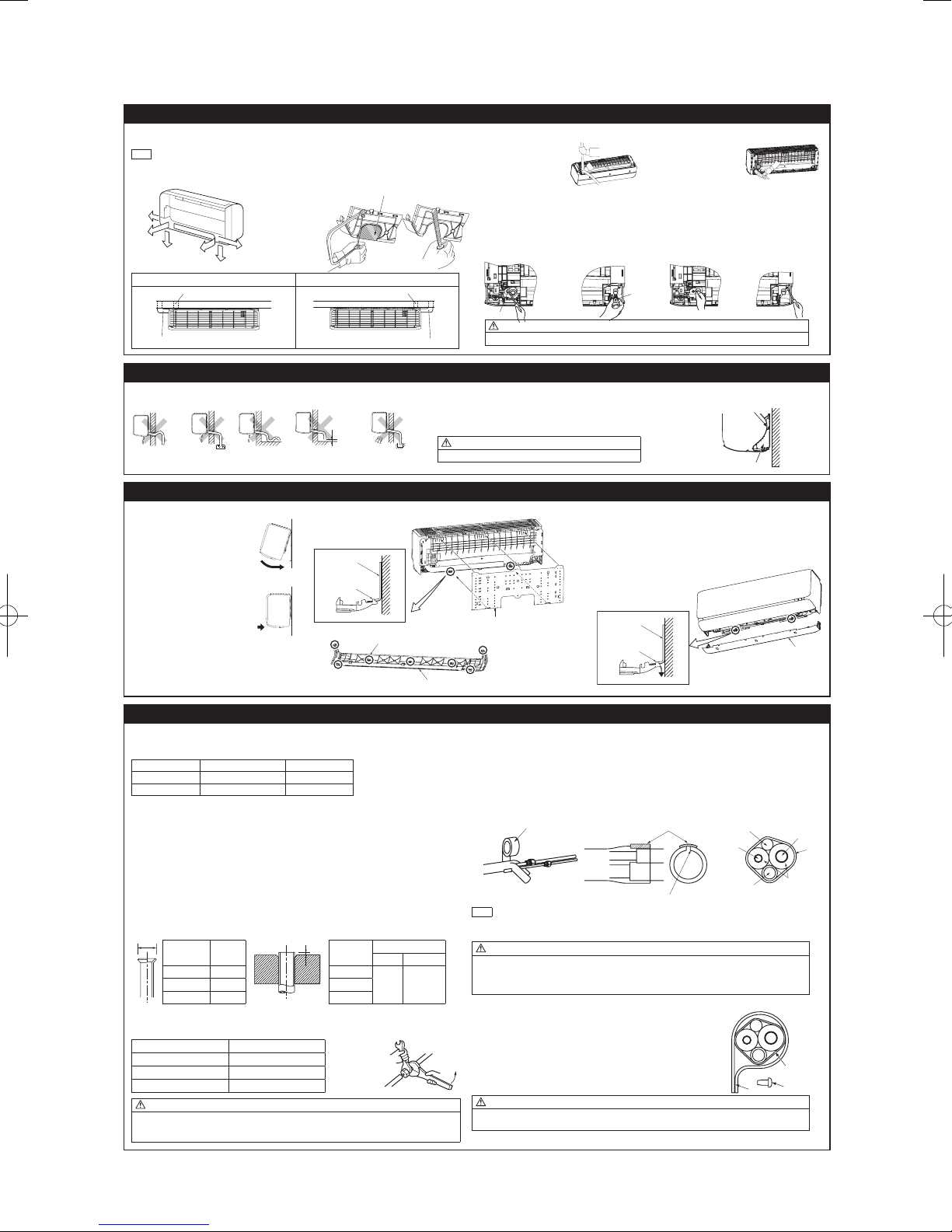
'17 • SRK-T-203
6. FORMING PIPING AND DRAIN HOSE
Cut out the panel smoothly along the
Right
Left downward
Left
Piping in the left direction
Piping in the left rear direction
Piping in the right rear direction
Piping in the right direction
(1)(2) (3)(4)
Higher than
specifie
Gutter
Pipe space
Indoor unit
Bottom panel
A
B
(Do not turn)
Liquid side
Tape
Insulation pad
Position it so that the slit area faces upward.
Connecting cable
Liquid pip
Drain hose
Gas pipe
Clamp
1. Forming piping
Piping is possible in the right, rear, downward, left, left rear or left downward direction.
NOTE
Sufcientcaremustbetakennottodamage
the panels when connecting pipes.
line in case of side or bottom piping.
Rear
Left
Downward
rear
Forming of pipings
• Hold the bottom of the
pipingandxdirection
before stretching it
and shaping it.
2.Drainchangeprocedures
(1) Remove the screw and drain hose.
(2) Remove the drain cap by hand or pliers.
(3) Insert the drain cap which was removed at procedure (2) securely using a hexagonal wrench etc.
(4) Install the drain hose and screw securely.
Pipings
Taping of the exterior
• Tape only the portion that
goes through the wall.
• Always tape the wiring
with the piping.
Left hand side piping Right hand side piping
7. DRAINAGE WORK
• Arrange the drain hose in a downward angle.
• Avoid the following drain piping.
The drain hose
tip is in water.
d
Wavy
8.INSTALLINGINDOORUNIT
1. Installing the indoor unit to installation board 2.Removingtheindoorunitfrominstallationboard
(1) Pass the pipe through the hole
in the wall, and hook the upper
part of the indoor unit to the
installation board.
(2)
Gently push the lower part to
fix the indoor unit base lower
latch to installation board.
(3) Install the latches of the bottom panel
(7 locations).
Secure the bottom panel with the 3 screws
(in the cap).
9. CONNECTING PIPING WORK
1. Preparation of connecting pipe
1.1. Selecting connecting pipe
Select connecting pipe according to the following table.
Gas pipe ø9.52 ø12.7
Liquid pipe ø6.35 ø6.35
• Pipe wall thickness must be greater than or equal to 0.8 mm.
• Pipe material must be O-type (Phosphorus deoxidized seamless copper pipe ICS 23.040.15, ICS
77.150.30).
1.2.Cuttingconnectingpipe
(1) Cut the connecting pipe to the required length with pipe cutter.
(2)
Hold the pipe downward and remove the burrs. Make sure that no foreign material enters the pipe.
(3) Cover the connecting pipe ends with the tape.
2.Pipingwork
2.1.Flaringpipe
(1)
Takeoutarenutsfromtheservicevalvesofindoorunitandengagethemontoconnectingpipes.
(2) Flarethepipesaccordingtotableandgureshownbelow.
Flare dimensions for R410A are different from those for conventional refrigerant.
Although itis recommendedto use thearing toolsdesigned specically forR410A, conventional
aringtools canalso be usedby adjustingthe measurement ofprotrusion Bwith a areadjustment
gauge.
2.2Connectingpipes
(1) Connect pipes on both liquid and gas sides.
(2)Tightennutstospeciedtorqueshowninthetablebelow.
Operation valve size (mm) Tightening torque (N·m)
ø6.35 (1/4") 14-18
ø9.52 (3/8") 34-42
ø12.7 (1/2") 49-61
CAUTION
• Donotapplyrefrigeratingmachineoiltothearedsurface.Itcancauserefrigerantleakage.
• Donotapplyexcesstorquetothearednuts.Thearednutsmaycrackresultinginrefrigerant
leakage.
Model SRK20/25/35 Model SRK50/60
Copperpipe
A
outer diameter
0
–0.4
ø6.35 9.1 ø6.35
ø12.7 16.6 ø12.7
The gap to the ground
is 5 cm or less.
Installation board
Indoor unit base latch
(2 locations)
outer diameter
Odor from
the gutter
Copperpipe
The drain hose tip
is in the gutter.
Wall
Latch (7 locations)
Rigid (clutch) type
R410A Conventional
0 - 0.5 1.0 - 1.5ø9.52 13.2 ø9.52
Gas side
Drain cap
Screw
CAUTION
Incorrect installation of drain hose and cap can cause water leakage.
• Pour water to the drain pan located under the heat exchanger, and ensure that the water is discharged outdoor.
• When extended drain hose is present inside the room, insulate it securely with heat insulator available in the market.
Since this air-conditioner is designed to collect dew drops on the rear surface to the
drain pan, do not install the connecting wire above the gutter.
CAUTION
Incorrect drainage work can cause water leakage.
(1) Remove the bottom panel. (Refer to 5.2)
(2) Pull the indoor unit base latch downward. (both right and left
hand sides). (The indoor unit base latch can be removed from the
installation board.)
(3) Push up the indoor unit upward so that it can be removed from
installation board.
Installation board
3. Heating and condensation prevention
(1) Dress the connecting pipes (both liquid and gas pipes) with insulation to prevent it from heating and
dew condensation.
Use the heat insulating material which can withstand 120°C or higher temperature. Make sure that insu
lation is wrapped tightly around the pipes and no gap is left between them.
(2) Wrap the refrigerant pipings of indoor unit with indoor unit heat insulation using tape.
(3) Coverthe are-connectedjoints (indoorside) with theindoor unitheat insulation andwrap itwith an
insulation pad (standard accessory provided with indoor unit).
(4) Wrap the connecting pipes, connecting cable and drain hose with the tape.
(2) (3) (4)
NOTE
Locations where relative humidity exceeds 70%, both liquid and gas pipes need to be dressed with 20mm
thicker heat insulation materials.
CAUTION
• Improper insulation can cause condensate(water) formation during cooling operation.
Condensate can leak or drip causing damage to household property.
• Poor heat insulating capacity can cause pipe outer surface to reach high temperature during heating
operation. It can cause cable deterioration and personal injury.
4. Finishing work
(1) Make sure that the exterior portion of connecting pipes, connecting cable
and drain hose is wrapped properly with tape. Shape the connecting pipes
to match with the contours of the pipe assembly route.
(2) Fix the pipe assembly with the wall using clamps and screws. Pipe assem-
bly should be anchored every 1.5m or less to isolate the vibration.
(3) Install the service cover securely. Water may enter the unit if service cover
is not installed properly, resulting in unit malfunction and failure.
CAUTION
Make sure that the connecting pipes do not touch the components within the unit. If pipes touch the
internal components, it may generate abnormal sounds and/or vibrations.
-
-
28
Installation board
Indoor unit base latch
(2 locations)
Wall
Wall
Bottom panel
e
Insulation
Pipe
assembly
Screw
Tape
-
or
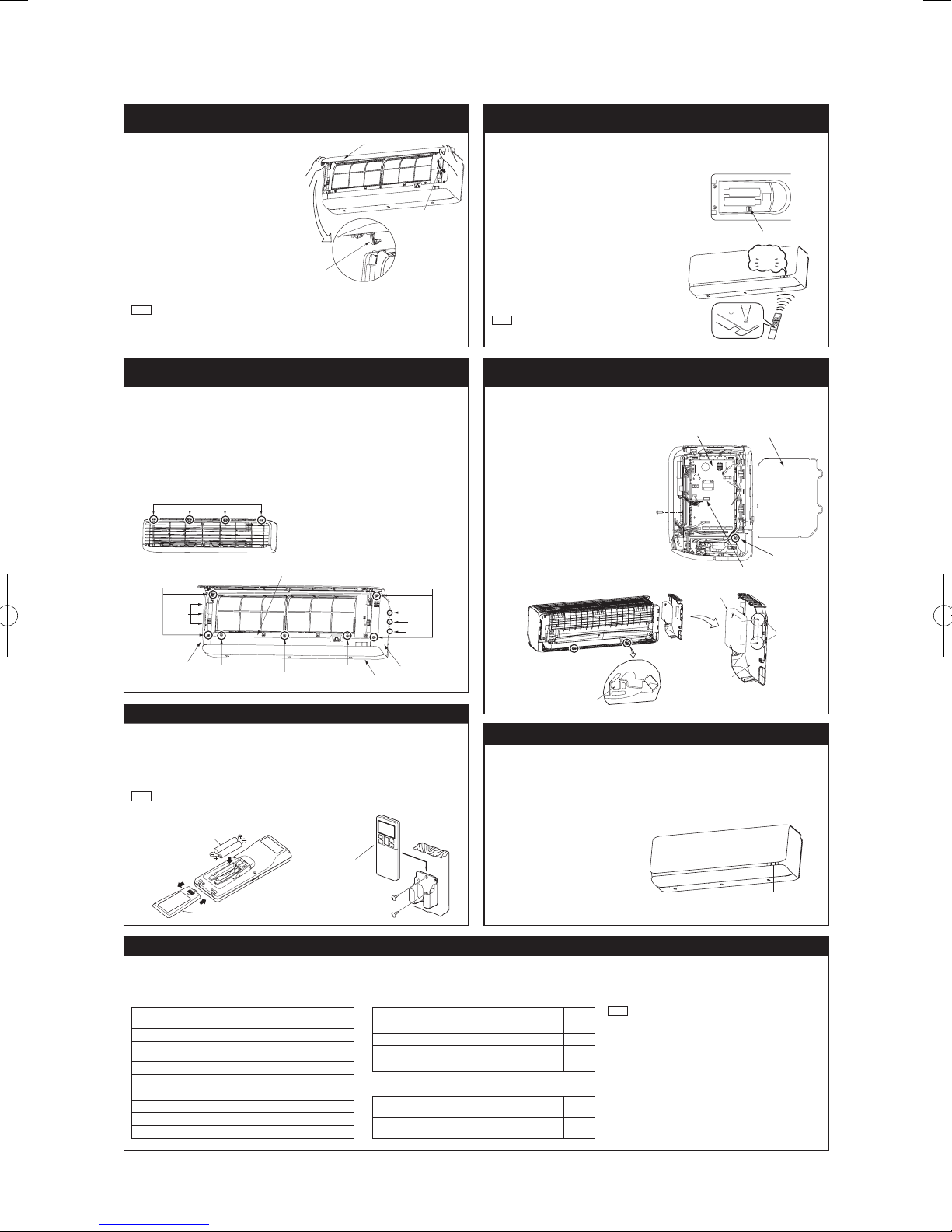
'17 • SRK-T-203
Air inlet panel
Panel ar
Cut
<Top view>
Scre
CNS terminal
<Right side>
Front panel
Bottom panel
)
Screw
Side panel (L)
Interface kit
Latch
cable through here.
Unit ON/OFF button
Wirekess
remote contro
Cover
Battery
10.HOWTOOPEN,CLOSE,REMOVEANDINSTALL
THE AIR INLET PANEL
1. Open
Pull the air inlet panel at both ends of lower part
and release latches, then pull up the panel until
you feel resistance.
(The panel stops at approx. 60° open position)
2.Close
Hold the panel at both ends of lower part, lower
it downward slowly, then push it slightly until the
latch works.
3. Removing
Open the panel by 80 degrees (as shown in the
right illustration) and then pull it forward.
4. Installing
Insert the panel arm into the slot on the front
panel from the position shown in right illustration,
hold the panel at both ends of lower part, lower
it downward slowly, then push it slightly until the
latch works.
NOTE
• When carrying out maintenance, handle the air
inlet panel with care.
m
Approx. 80°
11.HOWTOREMOVEANDINSTALLTHESIDEAND
FRONT PANEL
1. Side panel (R/L)
1.1. Removing
(1) Remove the 2 screws.
(2) Remove the 3 latches and then side panel
can be removed.
1.2.Installing
(1)Covertheunitwiththesidepanelandx
3 latches.
(2) Secure the side panel with the 2 screws.
Latch
2.Frontpanel
2.1.Removing
(1) Remove the side panel (R/L), the air inlet
panel,theairltersandthebottompanel.
(2) Remove the 3 screws.
(3) Remove the 4 upper latches and then front
panel can be removed.
2.2.Installing
(1)Covertheunitwiththefrontpanelandx4
upper latches.
(2) Secure the front panel with the 3 screws.
(3) Install the bottom panel, the side panel
(R/L),theairinletpanelandtheairlters.
Screw
Side panel (R
13.
INSTALLING TWO AIR-CONDITIONERS IN THE SAME ROOM
In case two air-conditioners are installed in the same room, apply this setting so that one unit can be
operated with only one wirelesss remote control.
Setting one wirelesss remote control
(1) Slide and take out the cover and batteries.
(2) Cut the switching line next to the battery with
wire cutters.
(3) Set the batteries and cover again.
Setting one indoor unit
(1) Turn off the power source and turn it on after
1 minute.
(2) Send the signal by pressing the ACL switch
on the wireless remote control that was set
according to the procedure described on the
above side.
(3) Check that the reception buzzer sound “peep”
is emitted from the indoor unit. Since the signal
is sent about 6 seconds after the ACL switch is
pressed, point the wireless remote control to the
indoor unit for a while.
NOTE
If no reception buzzer is emitted, restart the setting
from the beginning.
TIME SETUP ACL
Reception
Peep
14. TERMINAL CONNECTION FOR AN INTERFACE
To install wired remote control, superlink etc., interface kit is needed.
Remove the air inlet panel, bottom panel
(1)
and side panel (R).
(2) Remove the control cover. (Remove
the screw.)
(3) There is a terminal (respectively marked
with CNS) for the indoor control board.
While connecting an interface, connect
to the respective terminal securely with
the connection harness supplied with
an option “Interface kit SC-BIKN-E” and
fasten the connection harness onto the
indoor control box with the clamp and
screw supplied with the kit.
(4)
Hooktoxtheinterfacekittothe2
latches on side panel (L).
For more details, refer to the user’s
manual of “Interface kit SC-BIKN-E”.
w
Indoor PCB
Control cover
Fixing point of
the clamp
Latches
Side panel (L)
Screw (Front panel)
Latches
Side panel (R)
Pass the interface kit
12.INSTALLINGWIRELESSREMOTECONTROL
Mount the batteries
(1) Slide and take out the cover of backside.
(2) Mount the batteries [R03 (AAA, Micro),
×2 pieces] in the body properly.
(Fithepoleswiththeindicationmarks+&−)
(3) Set the cover again.
NOTE
• Do not use new and old batteries together.
• In case the unit is not operated for a long time,
take out the batteries
Installing remote control holder
(1) Select the place where the unit can receive
signals.
(2) Fix the holder to pillar or wall with wood
screws.
l
Wood screws
ø3.5 X 16
15. PUMP DOWN WORK
For the environmental protection, be sure to pump down when relocating or disposing of the unit.
Pump down is the method of recovering refrigerant from the indoor unit to the outdoor unit before
the connecting pipes are removed from the unit. When pump down is carried out, forced cooling
operation is needed.
Forced cooling operation
(1) Turn off the power source and turn it on
again after 1 minute. The air inlet panel
andapopenandclose.
(2) After the air inlet panel closes, press the
ON/OFF button continuously for at least 5
seconds. Then operation will start.
For the detail of pump down, refer to the
installation manual of outdoor unit.
16. INSTALLATION CHECK AND TEST RUN
Afternishingtheinstallationwork,checkthefollowingpointsagainbeforeturningonthepower.Conductatestrunandensurethattheunitoperatesproperly.
At the same time, explain to the customer how to use the unit and how to take care of the unit following the user’s manual.
Before test run
Before test run, check following points.
Power source voltage complies with the rated voltage
of air-conditioner.
Earth leakage breaker and circuit breaker are installed.
Powercableandconnectingcablearesecurelyxedto
the terminal block.
Both liquid and gas service valves are fully open.
No gas leaks from the joints of the service valves.
Indoor and outdoor side pipe joints have been insulated.
Hole on the wall is completely sealed with putty.
Drain hose and cap are installed properly.
Screw of the terminal cover is tightened securely.
Test run
Check following points during test run.
Indoor unit receives signal of wireless remote control.
Air-conditioning operation is normal.
There is no abnormal noise.
Water drains out smoothly.
Display of wireless remote control is normal.
After test run
Explain the operating and maintenance methods to the
user according to the user’s manual.
Keep this installation manual together with user’s
manual.
-
-
29
NOTE
During restart or change in operation mode, the unit will not start
operating for approximately 3 minutes. This is to protect the unit
and it is not malfunction.
Side panel (L)
 Loading...