

Mitsubishi Heavy Industries SRK20ZFX-S, SRC25ZFX-S, SRK35ZFX-S, SRK25ZFX-S, SRC35ZFX-S Technical Manual
...
-
3
-
INVERTER WALL MOUNTED TYPE
ROOM AIR-CONDITIONER
( Split system, air to air heat pump type )
SRK20ZFX-S, 25ZFX-S, 35ZFX-S, 50ZFX-S
TECHNICAL MANUAL
Collection data
Manual No. ’06
.
SRK-T
.
051

-
1
-
CONTENTS
1. GENERAL INFORMATION ........................................................................... 1
1.1 Specific features .................................................................................... 1
1.2 How to read the model name ................................................................ 1
2. SELECTION DATA........................................................................................ 2
2.1 Specifications ........................................................................................ 2
2.2 Range of usage & limitations ............................................................... 6
2.3 Exterior dimensions .............................................................................. 6
2.4 Piping system ........................................................................................ 8
2.5 Selection chart ....................................................................................... 9
3. ELECTRICAL DATA ..................................................................................... 10
3.1 Electrical wiring ..................................................................................... 10
4. OUTLINE OF OPERATION CONTROL BY MICROCOMPUTER ................12
4.1 Operation control function by remote control switch ........................ 12
4.2 Unit ON/OFF button ...............................................................................13
4.3 Power blackout auto restart function................................................... 13
4.4 Custom cord switching procedure ....................................................... 14
4.5 Flap and louver control .........................................................................14
4.6 Comfortable timer setting .....................................................................15
4.7 Sleep timer operation ............................................................................15
4.8 Outline of clean operation..................................................................... 15
4.9 Outline of heating operation ................................................................. 16
4.10 Outline of cooling operation ................................................................. 18
4.11 Outline of dehumidifying operation .....................................................19
4.12 Outline of automatic operation............................................................. 21
4.13 ECONOMY operation ............................................................................. 21
4.14 Protective control function ...................................................................22
5. APPLICATION DATA .................................................................................... 29
5.1 Selection of location for installation .................................................... 30
5.2 Installation of indoor unit ...................................................................... 31
5.3 Installation of outdoor unit ................................................................... 34
5.4 Refrigerant piping .................................................................................. 34
5.5 Test run ................................................................................................... 36
5.6 Precautions for wireless remote control installation and operation...... 36
6. MAINTENANCE DATA.................................................................................. 37
6.1 Troubleshooting procedures for electrical equipment ....................... 37
6.2 Servicing................................................................................................. 57
7. REFRIGERANT PIPING INSTALLATION/SERVICING MANUAL
FOR AIR CONDITIONERS USING R410A .................................................. 58
7.1 Outline .................................................................................................... 58
7.2 Refrigerant piping installation .............................................................. 59
7.3 Installation, removal and servicing ...................................................... 65
7.4 Refrigerant recovery.............................................................................. 70
-
1
-
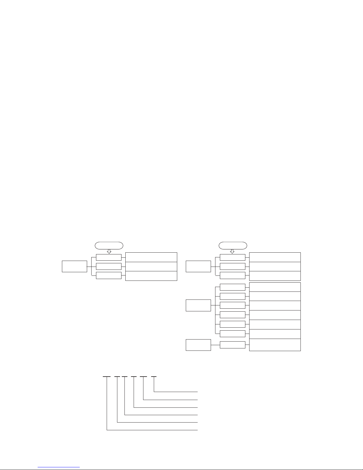
Over heat of compressor
Error of signal transmission
Outdoor fan motor error
1 GENERAL INFORMATION
1.1 Specific features
The “MITSUBISHI HEAVY INDUSTRIES, LTD.” room air-conditioner: SRK series are of split and wall mounted type and the unit
consists of indoor unit and outdoor unit with refrigerant precharged in factory. The indoor unit is composed of room air cooling or
heating equipment with operation control switch and the outdoor unit is composed of condensing unit with compressor.
(1) Inverter (Frequency converter) for multi-steps power control
¡ Heating/Cooling
The rotational speed of a compressor is changed in step in relation to varying load, interlocked with the indoor and outdoor unit
fans controlled to change frequency, thus controlling the capacity.
¡ Allowing quick heating/cooling operation during start-up period. Constant room temperature by fine-tuned control after the
unit has stabilized.
(2) Fuzzy control
¡ Fuzzy control calculates the amount of variation in the difference between the return air temperature and the setting tempera-
ture in compliance with the fuzzy rules in order to control the air capacity and the inverter frequency.
(3) Remote control flap & louver
The Flap & louver can be automatically controlled by operating wireless remote control.
¡ Flap swing : The flaps swing up and down successively.
¡ Louver swing : The louvers swing left and right successively.
¡ Memory flap : Once the Flap & louver position is set, the unit memorizes the position and continues to operate
at the same position from the next time.
(4) Self diagnosis function
¡ We are constantly trying to do better service to our customers by installing such judges that show abnormality of operation as
follows.
Outdoor heat exchanger sensor
error
Discharge pipe sensor error
Outdoor air temperature sensor
error
2 time flash
4 time flash
RUN light
keeps flashing
1 time flash
Trouble of outdoor unit
Over current
Current cut
2 time flash
3 time flash
RUN light
ON
1 time flash
5 time flash
TIMER light
Room temperature sensor error
Indoor fan motor error
Heat exchanger sensor error
2 time flash
6 time flash
TIMER light
ON
1 time flash
RUN light
Rotor lock
6 time flash
7 time flash
2 time flash
RUN light
2 time flash
1.2 How to read the model name
Example : SR K 35 Z FX - S
R410A models
Series No.
Inverter type
Product capacity
Wall mounted type
Split type room air-conditioner
-
2
-
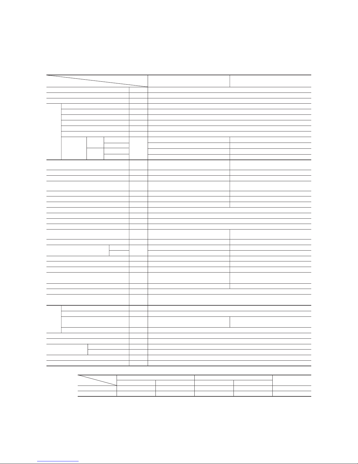
2 SELECTION DATA
2.1 Specifications
Model SRK20ZFX-S (Indoor unit)
SRC20ZFX-S (Outdoor unit)
Item
Model
SRK20ZFX-S SRC20ZFX-S
Cooling capacity
(1)
W 2000 (500~2800)
Heating capacity
(1)
W 2400 (500~4600)
Power source 1 Phase, 220-240V, 50Hz
Cooling input kW 0.37 (0.1~0.91)
Running current (Cooling) A 2.1/2.0/1.9
Heating input kW 0.44 (0.09~1.27)
Running current (Heating) A 2.5/2.4/2.3
Inrush current A 2.5/2.4/2.3
COP Cooling: 5.41 Heating: 5.45
Cooling
Sound level Hi 42, Me 34, Lo 21 44
Noise level
Power level
dB
57 57
Heating
Sound level Hi 42, Me 35, Lo 25 43
Power level 58 55
Exterior dimensions
Height × Width × Depth
mm
298 × 840 × 259 540 × 720 × 290
Color Cool white Stucco white
Net weight kg 12 35
Refrigerant equipment
Compressor type & Q’ty
– RM-B5077MD1 (Rotary type) × 1
Motor kW – 0.75
Starting method – Line starting
Heat exchanger Louver fins & inner grooved tubing Straight fins & inner grooved tubing
Refrigerant control Capillary tubes + Electronic expansion valve
Refrigerant
(3)
kg R410A 1.2 (Pre-Charged up to the piping length of 15m)
Refrigerant oil R 0.35 (MA68)
Deice control Microcomputer control
Air handling equipment
Fan type & Q’ty
Tangential fan × 1 Propeller fan × 1
Motor W 27 24
(Cooling) 11.8 30
Air flow (at High)
(Heating)
CMM
12 25
Air filter, Q’ty Polypropylene net (washable) × 2–
Shock & vibration absorber – Cushion rubber (for compressor)
Electric heater ––
Operation control
Operation switch
Wireless-Remote control –
Room temperature control Microcomputer thermostat –
Pilot lamp RUN (Green), TIMER (Yellow), HI POWER (Green), ECONO (Orange)
Safety equipment
O.D mm (in) Liquid line: φ6.35 (1/4″) Gas line: φ9.52 (3/8″)
Connecting method Flare connecting
Attached length of piping Liquid line: 0.54 m
Gas line : 0.47 m
–
Insulation Necessary (Both sides)
Drain hose Connectable
Power source cord 2 m (3 cores with Earth)
Size × Core number 1.5 mm2 × 4 cores (Including earth cable)
Connection wiring
Connecting method Terminal block (Screw fixing type)
Accessories (included)
Mounting kit, Clean filter (Allergen clear filter × 1, Photocatalytic washable deodorizing filter × 1)
Optional parts –
Notes (1) The data are measured at the following conditions.
Item Indoor air temperature Outdoor air temperature
Standards
Operation DB WB DB WB
Cooling 27ºC 19ºC 35ºC 24ºC ISO-T1, JIS C9612
Heating 20ºC – 7ºC 6ºC ISO-T1, JIS C9612
(2) The operation data are applied to the 220/230/240V districts respectively.
(3) The refrigerant quantity to be charged includes the refrigerant in 15 m connecting piping.
(Purging is not required even for the short piping.)
Operation data
(1)
Refrigerant
piping
Compressor overheat protection, Heating overload protection (High pressure control), Overcurrent protection,
Frost protection, Serial signal error protection, Indoor fan motor error protection, Cooling overload protection
The piping length is 7.5m.
(220/230/240V)
-
3
-
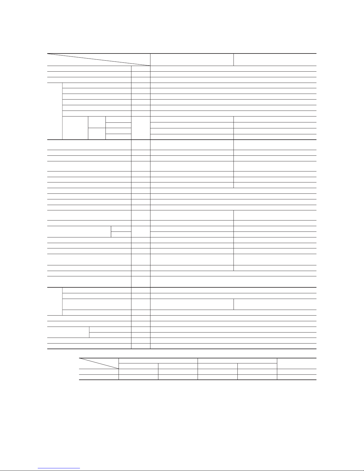
Item
Model
SRK25ZFX-S SRC25ZFX-S
Cooling capacity
(1)
W 2500 (500 ~ 3000)
Heating capacity
(1)
W 3000 (500 ~ 5000)
Power source 1 Phase, 220-240V, 50Hz
Cooling input kW 0.50 (0.10 ~ 0.64)
Running current (Cooling) A 2.5/2.4/2.3
Heating input kW 0.59 (0.09 ~ 1.16)
Running current (Heating) A 2.9/2.8/2.7
Inrush current A 2.9/2.8/2.7
COP Cooling: 5.00 Heating: 5.08
Cooling
Sound level Hi 43, Me 34, Lo 21 45
Noise level
Power level
dB
58 58
Heating
Sound level Hi 43, Me 36, Lo 26 47
Power level 59 59
Exterior dimensions
Height × Width × Depth
mm
298 × 840 × 259 540 × 720 × 290
Color Cool white Stucco white
Net weight kg 12 35
Refrigerant equipment
Compressor type & Q’ty
– RM-B5077MD1 (Rotary type) × 1
Motor kW – 0.75
Starting method – Line starting
Heat exchanger Louver fins & inner grooved tubing Straight fins & inner grooved tubing
Refrigerant control Capillary tubes + Electronic expansion valve
Refrigerant
(3)
kg R410A 1.2 (Pre-Charged up to the piping length of 15m)
Refrigerant oil R 0.35 (MA68)
Deice control Microcomputer control
Air handling equipment
Fan type & Q’ty
Tangential fan × 1 Propeller fan × 1
Motor W 27 24
(Cooling) 11.8 30
Air flow (at High)
(Heating)
CMM
12 27
Air filter, Q’ty Polypropylene net (washable) × 2–
Shock & vibration absorber – Cushion rubber (for compressor)
Electric heater ––
Operation control
Operation switch
Wireless-Remote control –
Room temperature control Microcomputer thermostat –
Pilot light RUN (Green), TIMER (Yellow), HI POWER (Green), ECONO (Orange)
Safety equipment
O.D mm (in) Liquid line: φ6.35 (1/4″) Gas line: φ9.52 (3/8″)
Connecting method Flare connecting
Attached length of piping Liquid line: 0.54 m
Gas line : 0.47 m
–
Insulation Necessary (Both sides)
Drain hose Connectable
Power source cord 2 m (3 cores with Earth)
Size × Core number 1.5 mm2 × 4 cores (Including earth cable)
Connection wiring
Connecting method Terminal block (Screw fixing type)
Accessories (included)
Mounting kit, Clean filter (Allergen clear filter × 1, Photocatalytic washable deodorizing filter × 1)
Optional parts –
Notes (1) The data are measured at the following conditions.
Item Indoor air temperature Outdoor air temperature
Standards
Operation DB WB DB WB
Cooling 27ºC 19ºC 35ºC 24ºC ISO-T1, JIS C9612
Heating 20ºC – 7ºC 6ºC ISO-T1, JIS C9612
(2) The operation data are applied to the 220/230/240V districts respectively.
(3) The refrigerant quantity to be charged includes the refrigerant in 15 m connecting piping.
(Purging is not required even for the short piping.)
Operation data
(1)
Refrigerant
piping
Compressor overheat protection, Heating overload protection (High pressure control), Overcurrent protection,
Frost protection, Serial signal error protection, Indoor fan motor error protection, Cooling overload protection
The piping length is 7.5m.
(220/230/240V)
Model SRK25ZFX-S (Indoor unit)
SRC25ZFX-S (Outdoor unit)
-
4
-
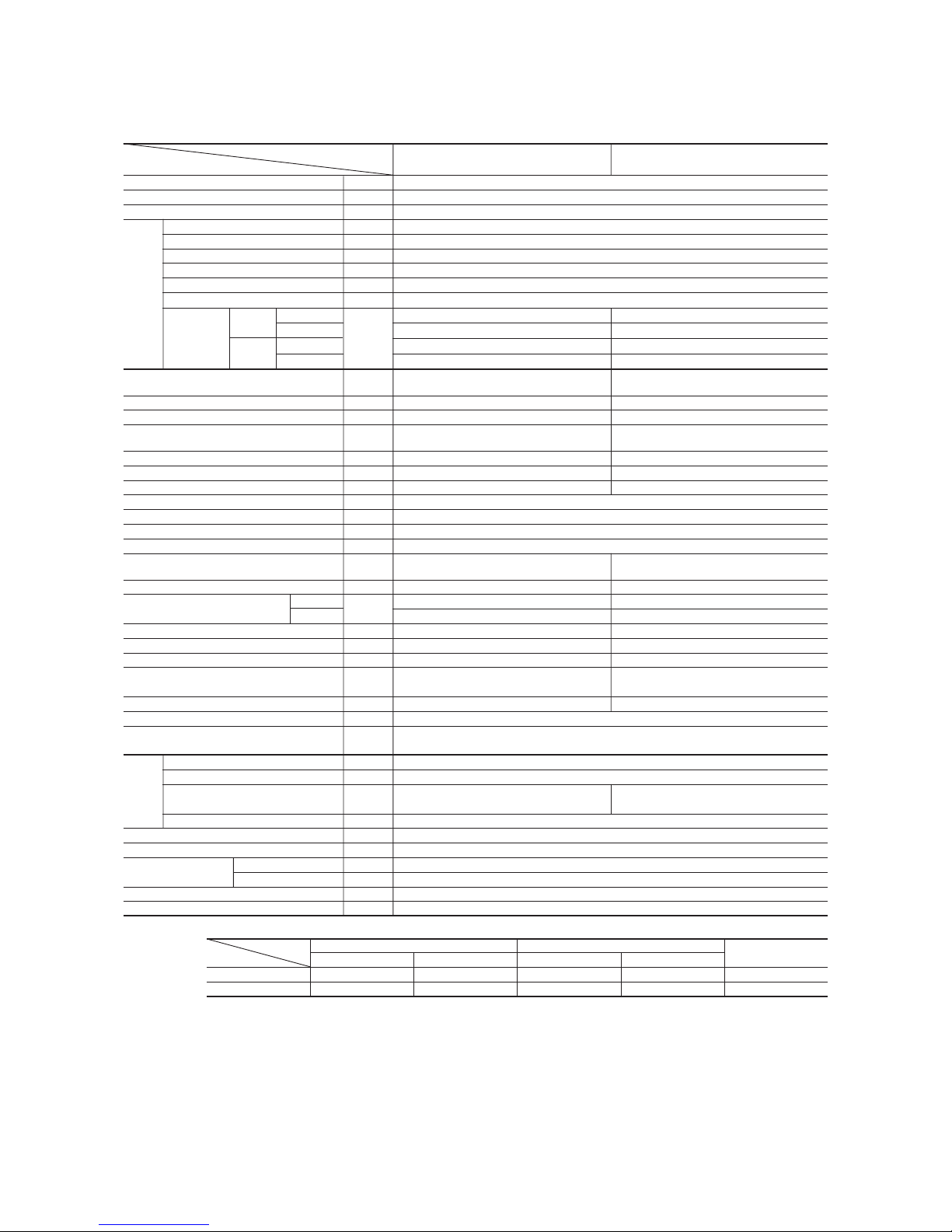
Item
Model
SRK35ZFX-S SRC35ZFX-S
Cooling capacity
(1)
W 3500 (500 ~ 3900)
Heating capacity
(1)
W 4200 (500 ~ 5100)
Power source 1 Phase, 220-240V, 50Hz
Cooling input kW 0.87 (0.10 ~ 0.98)
Running current (Cooling) A 4.2/4.0/3.8
Heating input kW 1.00 (0.09 ~ 1.19)
Running current (Heating) A 4.9/4.7/4.5
Inrush current A 4.9/4.7/4.5
COP Cooling: 4.02 Heating: 4.20
Cooling
Sound level Hi 44, Me 35, Lo 22 47
Noise level
Power level
dB
59 60
Heating
Sound level Hi 44, Me 37 , Lo 27 50
Power level 60 63
Exterior dimensions
Height × Width × Depth
mm
298 × 840 × 259 540 × 720 × 290
Color Cool white Stucco white
Net weight kg 12 35
Refrigerant equipment
Compressor type & Q’ty
– RM-B5077MD1 [Rotary type] × 1
Motor kW – 0.90
Starting method – Line starting
Heat exchanger Louver fins & inner grooved tubing Straight fins & inner grooved tubing
Refrigerant control Capillary tubes + Electronic expansion valve
Refrigerant
(3)
kg R410A 1.2 (Pre-Charged up to the piping length of 15m)
Refrigerant oil R 0.35 (MA68)
Deice control Microcomputer control
Air handling equipment
Fan type & Q’ty
Tangential fan × 1 Propeller fan × 1
Motor W 27 24
(Cooling) 12 30
Air flow (at High)
(Heating)
CMM
12.2 27
Air filter, Q’ty
Polypropylene net (washable) × 2
–
Shock & vibration absorber – Cushion rubber (for compressor)
Electric heater ––
Operation control
Operation switch
Wireless-Remote control –
Room temperature control Microcomputer thermostat –
Pilot light RUN (Green), TIMER (Yellow), HI POWER (Green), ECONO (Orange)
Safety equipment
O.D mm (in) Liquid line: φ6.35 (1/4″) Gas line: φ9.52 (3/8″)
Connecting method Flare connecting
Attached length of piping Liquid line: 0.54 m
Gas line : 0.47 m
–
Insulation Necessary (Both sides)
Drain hose Connectable
Power source cord 2 m (3 cores with Earth)
Size × Core number 1.5 mm2 × 4 cores (Including earth cable)
Connection wiring
Connecting method Terminal block (Screw fixing type)
Accessories (included)
Mounting kit, Clean filter (Allergen clear filter × 1, Photocatalytic washable deodorizing filter × 1)
Optional parts –
Notes (1) The data are measured at the following conditions.
Model SRK35ZFX-S (Indoor unit)
SRC35ZFX-S (Outdoor unit)
Item Indoor air temperature Outdoor air temperature
Standards
Operation DB WB DB WB
Cooling 27ºC 19ºC 35ºC 24ºC ISO-T1, JIS C9612
Heating 20ºC – 7ºC 6ºC ISO-T1, JIS C9612
(2) The operation data are applied to the 220/230/240V districts respectively.
(3) The refrigerant quantity to be charged includes the refrigerant in 15 m connecting piping.
(Purging is not required even for the short piping.)
Operation data
(1)
Refrigerant
piping
Compressor overheat protection, Heating overload protection (High pressure control), Overcurrent protection,
Frost protection, Serial signal error protection, Indoor fan motor error protection, Cooling overload protection
The piping length is 7.5m.
(220/230/240V)

-
5
-
Model SRK50ZFX-S (Indoor unit)
SRC50ZFX-S (Outdoor unit)
Item
Model
SRK50ZFX-S SRC50FX-S
Cooling capacity
(1)
W 5000 (600~5300)
Heating capacity
(1)
W 6000 (600~7900)
Power source 1 Phase, 220-240V, 50Hz
Cooling input kW 1.56 (0.12~2.1)
Running current (Cooling) A 7.5/7.2/6.9
Heating input kW 1.66 (0.11~2.71)
Running current (Heating) A 7.9/7.6/7.3
Inrush current A 7.9/7.6/7.3
COP Cooling: 3.21 Heating: 3.61
Cooling
Sound level Hi 45, Me 38, Lo 26 48
Noise level
Power level
dB
60 61
Heating
Sound level Hi 47, Me 39, Lo 24 50
Power level 62 65
Exterior dimensions
Height × Width × Depth
mm
298 × 840 × 259 640 × 850 × 290
Color Cool white Stucco white
Net weight kg 12 43
Refrigerant equipment
Compressor type & Q’ty
– 5CS102XFA [Scroll type] × 1
Motor kW – 1.5
Starting method – Line starting
Heat exchanger Slit fins + Louver fins & inner grooved tubing Straight fins & inner grooved tubing
Refrigerant control Capillary tubes + Electronic expansion valve
Refrigerant
(3)
kg R410A 1.35 (Pre-Charged up to the piping length of 15m)
Refrigerant oil R 0.36 (RB68A)
Deice control Microcomputer control
Air handling equipment
Fan type & Q’ty
Tangential fan × 1 Propeller fan × 1
Motor W 27 34
(Cooling) 12.5 42
Air flow (at High)
(Heating)
CMM
13.5 42
Air filter, Q’ty
Polypropylene net (washable) × 2
–
Shock & vibration absorber – Cushion rubber (for compressor)
Electric heater ––
Operation control
Operation switch
Wireless-Remote control –
Room temperature control Microcomputer thermostat –
Pilot lamp RUN (Green), TIMER (Yellow), HI POWER (Green), ECONO (Orange)
Safety equipment
O.D mm (in) Liquid line: φ6.35 (1/4″) Gas line: φ12.7 (1/2″)
Connecting method Flare connecting
Attached length of piping Liquid line: 054 m
Gas line : 0.47 m
–
Insulation Necessary (Both sides)
Drain hose Connectable
Power source cord 2 m (3 cores with Earth)
Size × Core number 1.5 mm2 × 4 cores (Including earth cable)
Connection wiring
Connecting method Terminal block (Screw fixing type)
Accessories (included)
Mounting kit, Clean filter (Allergen clear filter × 1, Photocatalytic washable deodorizing filter × 1)
Optional parts –
Notes (1) The data are measured at the following conditions.
Item Indoor air temperature Outdoor air temperature
Standards
Operation DB WB DB WB
Cooling 27ºC 19ºC 35ºC 24ºC ISO-T1, JIS C9612
Heating 20ºC – 7ºC 6ºC ISO-T1, JIS C9612
(2) The operation data are applied to the 220/230/240V districts respectively.
(3) The refrigerant quantity to be charged includes the refrigerant in 15 m connecting piping.
(Purging is not required even for the short piping.)
If the piping length is longer, when it is 15 to 25m, add 20 g refrigerant per meter.
Operation data
(1)
Refrigerant
piping
Compressor overheat protection, Heating overload protection (High pressure control), Overcurrent protection,
Frost protection, Serial signal error protection, Indoor fan motor error protection, Cooling overload protection
The piping length is 7.5m.
(220/230/240V)

-
6
-
2.2 Range of usage & limitations
Indoor return air temperature
(Upper, lower limits)
Refrigerant line (one way) length Max. 15m
SRK20ZFX-S, 25ZFX-S, 35ZFX-S SRK50ZFX-S
Cooling operation: Approximately 21 to 32°C
Heating operation: Approximately 15 to 30°C
Cooling operation: Approximately -15 to 43°C
Heating operation: Approximately -5 to 21°C
Power source voltage Rating ± 10%
Voltage at starting Min. 85% of rating
Frequency of ON-OFF cycle
ON and OFF interval Max. 3 minutes
Max. 4 times/h
(Inching prevention: 10 min.)
Max. 7 times/h
(Inching prevention: 5 min.)
Outdoor air temperature
(Upper, lower limits)
Vertical height difference between
outdoor unit and indoor unit
Max. 10m (Outdoor unit is higher)
Max. 10m (Outdoor unit is lower)
Max. 25m
Max. 15m (Outdoor unit is higher)
Max. 15m (Outdoor unit is lower)
Item
Models
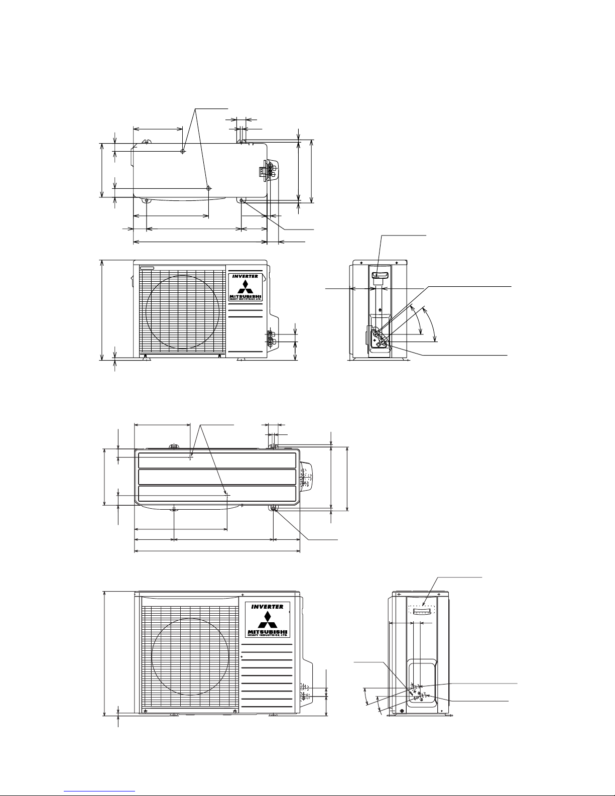
2.3 Exterior dimensions
(1) Indoor unit
Models All models
840
298
A
Piping hole right
259
9
44
right: 67
left : 60
3
60
60
14.5
813
603
44
44
60
60
VIEW A
44.5
47.5220.5
50
207.5
73.5
53.5
Piping hole (ø65)
Piping hole (ø65)
Indoor unit
Installating board
Drain hose 515 (ø16)
Piping for gas 533.5
)(
20,25,35: ø9.52
50: ø12.7
Piping for liquid 603.5 (ø6.35)
63.5
8.5
5.3
284.2
44.5
73.5
182.5
50
450
693
25
-
7
-
(2) Outdoor unit
Models SRC20ZFX-S, 25ZFX-S, 35ZFX-S
Unit: mm
290
540
14.4
47.4 42.6
264.5
71
404.5
510
720
17.8
Drain holes
50
12
39.7
99.9
340
312.5
13.5
14
139
2-16 x12
61.9
139.3 33.3
Flare connection ø6.35 (1/4")
Service valve (Liquid)
40
°
40
°
Flare connecting ø9.52 (3/8")
Service valve (Gas)
Terminal block
Drain holes
286.4
12
50
290
49.6
43.5
850
203.1
510 136.9
476
2-16 × 12
314
12
328
Terminal block
Service valve (Liquid)
ø6.35 (1/4'')
Service valve (Gas)
ø12.7 (1/2'')
Ground
terminal
124
34.6
20˚
20˚
42.7
100.3
15
640
14
Model SRC50ZFX-S

-
8
-
2.4 Piping system
Models SRK20ZFX-S, 25ZFX-S, 35ZFX-S
Outdoor unitIndoor unit
Room temp.
sensor
Heat
exchanger
Flare connection
Heat
exchanger
sensor
Piping
(Liquid)
ø6.35
Check joint
4 way valve
Service valve (Liquid)
Flare connetion
Discharge pipe
temp. sensor
Cooling cycle
Heating cycle
Outdoor air
temp. sensor
Heat
exchanger
Heat exchanger
sensor
Compressor
Capillary tube
Strainer
Accumulator
Service valve
(Gas)
Electronic
expansion valve
Piping
(Gas)
ø9.52
Model SRK50ZFX-S
Outdoor unitIndoor unit
Room temp.
sensor
Heat
exchanger
Flare connection
Heat
exchanger
sensor
Piping
(Liquid)
ø6.35
Check joint
4 way valve
Service valve (Liquid)
Flare connection
Discharge pipe
temp. sensor
Cooling cycle
Heating cycle
Outdoor air
temp. sensor
Heat
exchanger
Heat exchanger
sensor
Compressor
Capillary tube
Strainer
Strainer
Service valve
(Gas)
Capillary tube
Electronic
expansion valve
Piping
(Gas)
ø12.7
Muffler
Capillary tube
-
9
-
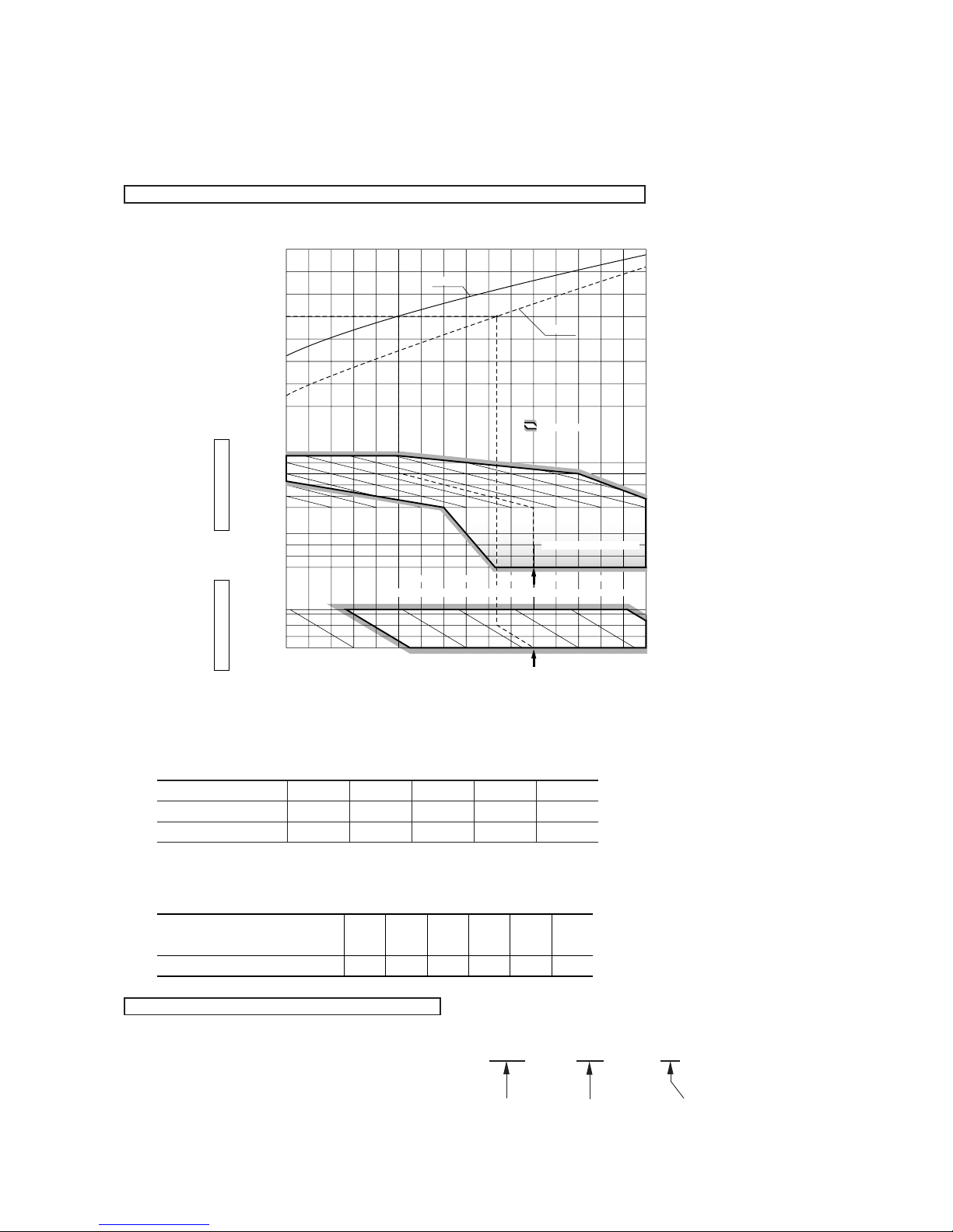
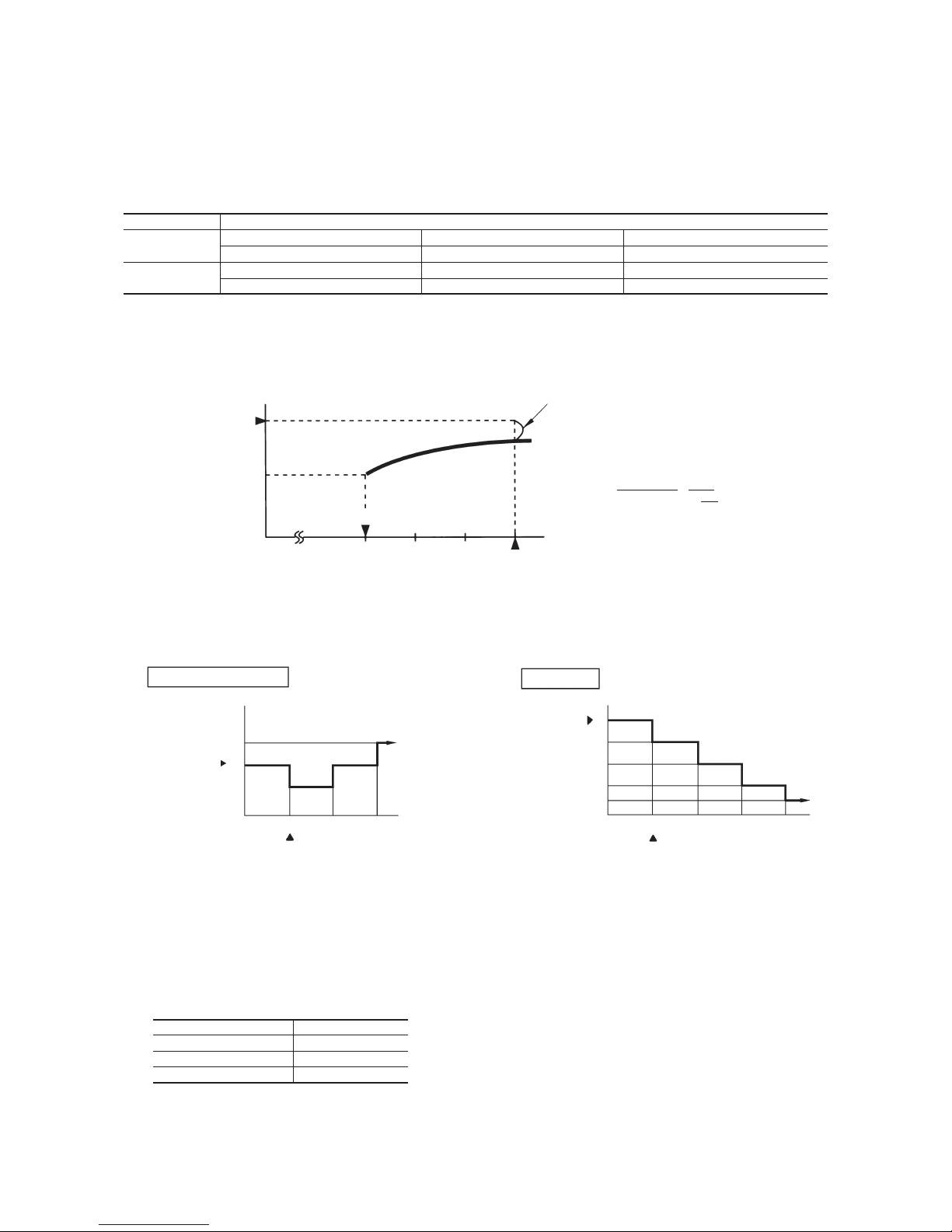
2.5 Selection chart
Correct the cooling and heating capacity in accordance with the conditions as follows. The net cooling and heating capacity can be
obtained in the following way.
Net capacity = Capacity shown on specification ✕ Correction factors as follows.
(1) Coefficient of cooling and heating capacity in relation to temperatures
(2) Correction of cooling and heating capacity in relation to one way length of refrigerant piping
It is necessary to correct the cooling and heating capacity in relation to the one way piping length between the indoor and outdoor
units.
(3) Correction relative to frosting on outdoor heat exchanger during heating
In additions to the foregoing corrections (1), (2) the heating capacity needs to be adjusted also with respect to the frosting on the
outdoor heat exchanger.
How to obtain the cooling and heating capacity
Example : The net cooling capacity of the model SRK35ZFX-S with the piping length of 15m, indoor wet-bulb temperature at 19.0˚C
and outdoor dry-bulb temperature 35˚C is Net cooling capacity = 3500 ✕ 0.975 ✕ 1.0 = 3413 W
SRK35ZFX-S Length 15m
Factor by air
temperatures
0.6
0.7
0.8
0.9
1.0
1.2
1.1
1.3
0
-5
-10
-15
Coefficient of cooling &
Heating capacity in
relation to temperature
Heating operation
Indoor air D.B.
temperature
°C D. B.
Cooling operation
Outdoor air D.B.
temperature
°C D. B.
10
15
20
25
27
20
25
30
35
40
43
15010-5-10-15 5
24
26
2220181614
Applicable range
Cooling
Heating
ISO-T1 Standard Condition
Indoor air W.B. temperature °C W.B.
Depends on installed situation
Outdoor air W.B. temperature °C W.B.
ISO-T1 Standard Condition
Piping length [m]
Cooling
Heating
7
1.0
1.0
10
0.99
1.0
15
0.975
1.0
20
0.965
1.0
25
0.95
1.0
Air inlet temperature of
outdoor unit in ˚C WB
Adjustment coefficient
-5
0.91-30.88-10.8610.8730.9251.00

-
10
-
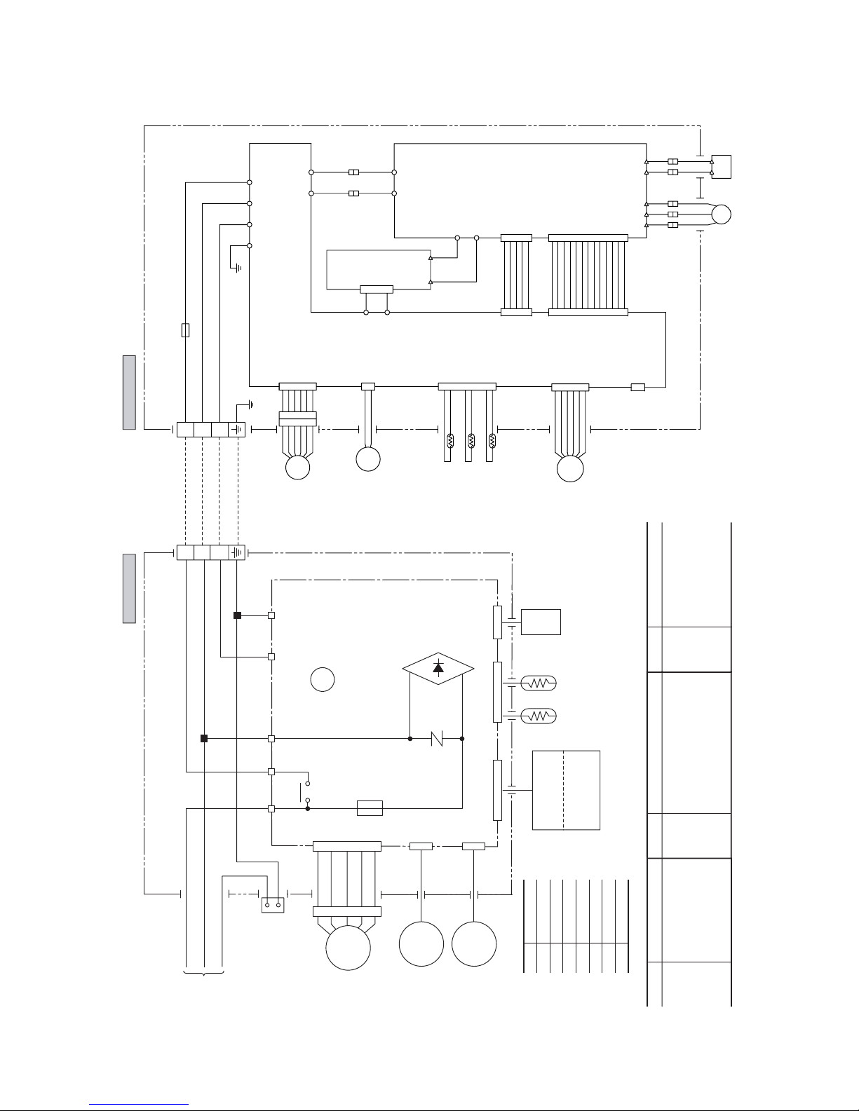
3 ELECTRICAL DATA
3.1 Electrical wiring
Models SRK20ZFX-S, 25ZFX-S, 35ZFX-S
Power source
1 Phase
220-240V 50Hz
Outdoor unit
Indoor unit
HEAT
EXCHANGER
Printed circuit
board
Printed circuit board
BR
BL
Y/GN
BK
WH
RD
RD
1
3
4
5
6
CNU
BK
WH
Y
BL
TB TB
F2 (250V 20A)
F1
250V
3.15A
BK
WH
RD
U
V
W
BK
C2 S.IN R.IN
Re
G
WH
RD
Y/GN
N
ZNR
CNM
CNE CNG
52C3
52C
52C4
J
Th4
Th1 Th2
Th5
Th6
CNB
CNE
CNA
CND
1
2
3
NP
Power
transistor
20S
52C
EEV
FMo
DS
CM
1
2
3
( )
FM
I
SM
CNX
LM
Display
Wireless
R-Amp
Black
Brown
Red
Blue
White
Yellow/Green
BK
BR
RD
BL
WH
Y/GN
Color symbol
Meaning of marks
Symbol
Parts name
CM
Compressor motor
F
Fuse
FM
I
Fan motor (Outdoor)
Fan motor (Indoor)
FMo
FSM
LM
Flap motor
Louver motor
Symbol
Parts name
Th
1
Room temp. sensor
Th
2
Heat exchanger sensor (Indoor unit)
Th
4
Heat exchanger sensor (Outdoor unit)
Th
5
Outdoor air temp. sensor
Th
6
Discharge temp. sensor
Symbol
Parts name
20S
4 way valve (coil)
RE
Reactor
ZNR
Varistor
52C
Magnetic contactor
DS
Diode stack
EEV
Electronic expansion valve
-
11
-
Power source
1 Phase
220-240V 50Hz
Outdoor unit
Indoor unit
HEAT
EXCHANGER
Printed circuit board
BRBLY/GN
BK
WH
RD
RD
BK
WH
Y
BL
TB
F1
250V
3.15A
N
ZNR
CNM
CNE CNG CNF
52C3
52C
52C4
J
52C
1
2
3
( )
FM
I
SM
CNX
LM
Display
Wireless
R-Amp
Th1 Th2
Th3
13456
CNU
Black
Brown
Red
Blue
White
Yellow/Green
BKBRRD
BL
Orange
OR
Green
GR
WH
Y/GN
Color symbol
Meaning of marks
Symbol
Parts name
CFo
Capacitor for FMo
CM
Compressor motor
F
Fuse
FM
I
Fan motor (Outdoor)
Fan motor (Indoor)
FMo
FSM
LM
L
Flap motor
Louver motor
Inductor
Symbol
Parts name
Th
1
Room temp. sensor
Th
2
Heat exchanger sensor (Indoor unit)
Th
3
Humidity sensor
Th
4
Heat exchanger sensor (Outdoor unit)
Th
5
Outdoor air temp. sensor
Th
6
Discharge pipe temp. sensor
Symbol
Parts name
ZNR
Varistor
20S
4 way valve (coil)
52C
Magnetic contactor
DS
Diode stack
EEV
Electronic expansion valve
N_1
P_1
BK
RD
N_1
P_1
DC-N
DC-P
PWB3 (CAPACITOR)
BK
RD
CNG
PWB1 (MAIN)
PWB2 (POWER)
EEV
Th4
Th5
Th6
CNT
TB
CNJ
CND
CNB
FMo
20S
F(250V 15A)
BK
1
L-1
AC.N
AC.N AC.L
AC.L
BL
GR
BL
GR
L
AF_L2
AF_L1
OR
OR
V
CM
W
BK
RD
WH
OR
OR
BK
RD
WH
U
CNH
CNG
G3
CNH
CNG
RD
Y/GN
CNI
WH
2
N-1
3
CNO.1
Model SRK50ZFX-S
-
12
-
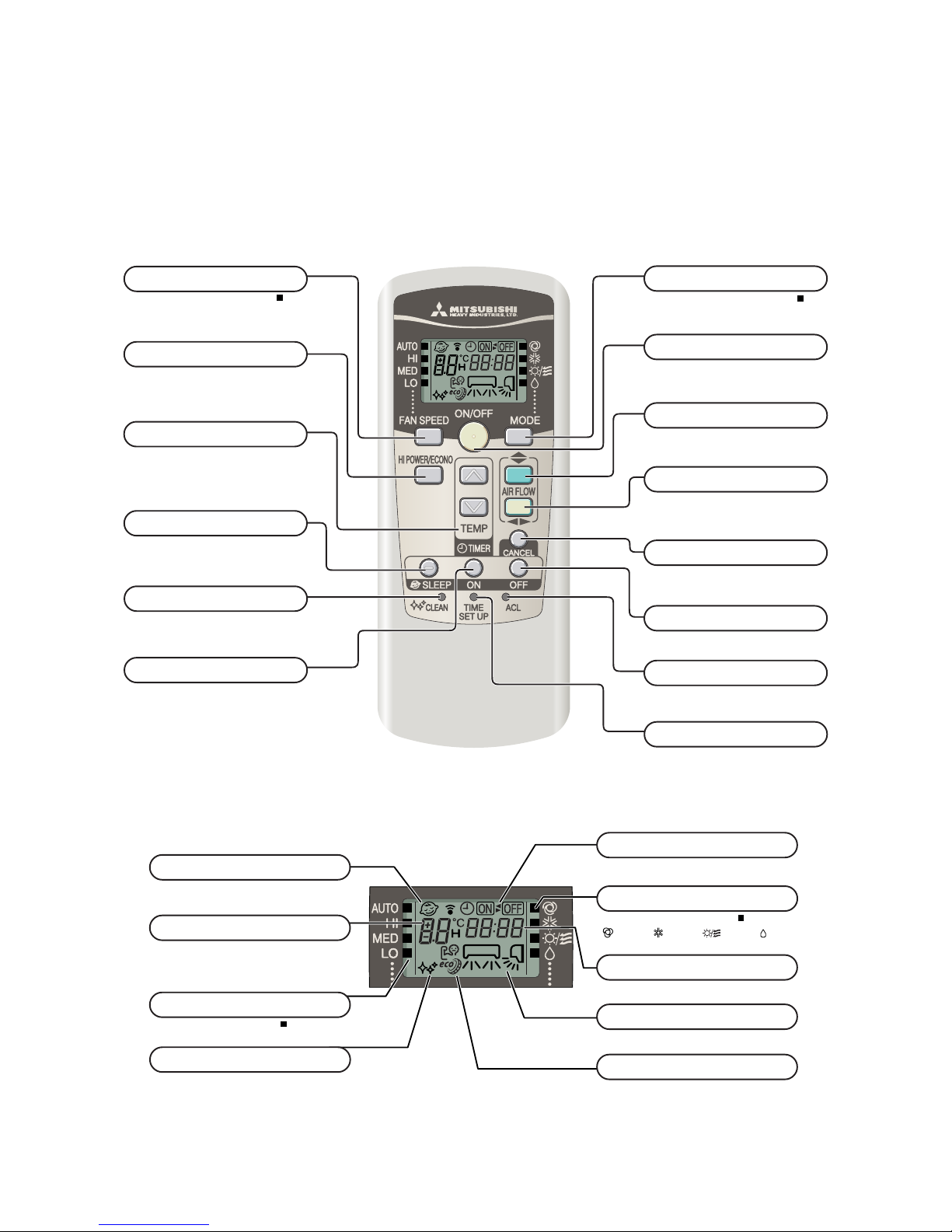
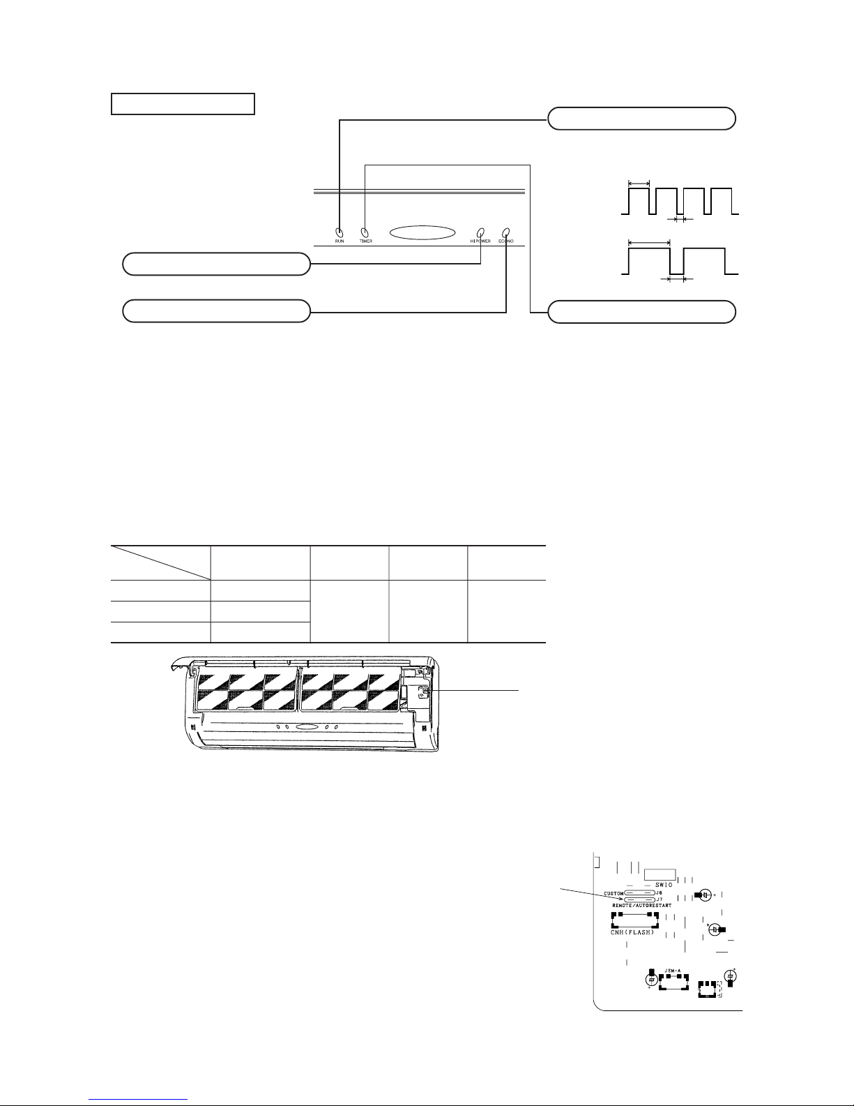
S Indication section
Models All models
S Operation section
4 OUTLINE OF OPERATION CONTROL BY MICROCOMPUTER
4.1 Operation control function by remote control switch
Wireless remote control
FAN SPEED button
Each time the button is pushed, the indicator is switched over in turn.
• The above illustration shows all controls, but in practice
only the relevant parts are shown.
OPERATION MODE select button
Each time the button is pushed, the indicator is switched over in turn.
ON/OFF (luminous) button
Press for starting operation, press again for
stopping.
HI POWER/ECONO button
This button changes the HIGH POWER/
ECONOMY mode.
AIR FLOW (UP/DOWN) button
This button changes the air flow (up/down)
mode.
TIME SET UP switch
This switch for setting the time.
SLEEP button
This button changes to SLEEP operation.
CLEAN switch
This switch changes the CLEAN mode.
ON TIMER button
This button selects ON TIMER operation.
TEMPERATURE button
This button sets the room temperature.
(This button changes the present time and
TIMER time.)
OFF TIMER button
This button selects OFF TIMER operation.
RESET switch
Switch for resetting microcomputer.
OPERATION MODE indicator
Indicates selected operation with lamp.
[
(Auto) • (Cool) • (Heat) • (Dry)]
TEMPERATURE indicator
Indicates set temperature.
(Does not indicate temperature when operation
mode is on AUTO)
FAN SPEED indicator
Indicates set air flow rate with lamp.
CLEAN indicator
Indicates during CLEAN operation.
SLEEP indicator
Indicates during SLEEP operation.
ON/OFF TIMER indicator
Indicates during ON/OFF TIMER operation.
TIME indicator
Indicates present time or timer setting time.
AIR FLOW indicator
Shows selected flap and louver mode.
AIR FLOW (LEFT/RIGHT) button
This button changes the air flow (left/right)
mode.
CANCEL button
This button cancels the ON timer, OFF
timer, and SLEEP operation.
HI POWER/ ECONO MODE indicator
Indicates during High power/economy mode operation.
-
13
-
4.2 Unit ON/OFF button
When the remote control batteries become weak, or if the remote control is lost or malfunctioning, this button may be used to turn the
unit on and off.
(a) Operation
Push the button once to place the unit in the automatic mode. Push it once more to turn the unit off.
(b) Details of operation
The unit will go into the automatic mode in which it automatically determines, from room temperature (as detected by sensor),
whether to go into the cooling, thermal dry or heating modes.
Function
Room temperature
Operation mode
setting
Fan speed Flap Timer switch
Cooling About 25ºC
Thermal dry About 25ºC Auto Auto Continuous
Heating About 26ºC
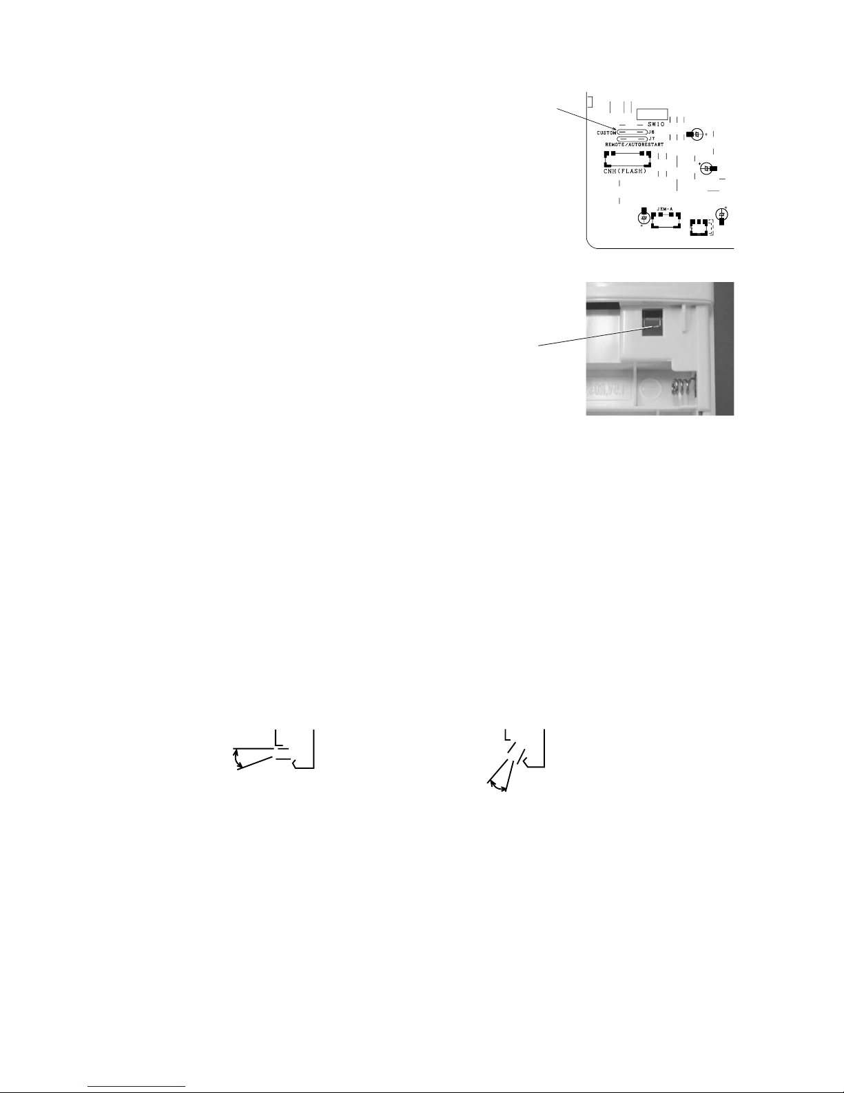
4.3 Power blackout auto restart function
(1) Power blackout auto restart function is a function that records the operational status of the air-conditioner immediately prior to it
being switched off by a power cut, and then automatically resumes operations at that point after the power has been restored.
(2) The following settings will be cancelled:
(a) Timer settings
(b) High-power operations
Notes (1) The power blackout auto restart function is set at on when the air-conditioner is shipped from the factory.
Consult with your dealer if this function needs to be switched off.
(2) When power failure ocurrs, the timer setting is cancelled. Once power is resumed, reset the timer.
(3)
If the jumper wire (J7) “REMOTE/AUTORESTART” is cut, auto restart is disabled. (See the diagram at right)
Unit ON/OFF button
Jumper wire (J7)
Unit indication section
Models All models
ECONOMY light (orange)
Illuminates during ECONOMY operation.
TIMER light (yellow)
Illuminates during TIMER operation.
HI POWER light (green)
Illuminates during HIGH POWER operation.
RUN (HOT KEEP) light (green)
• Illuminates during operation.
• Brinks at air flow stop due to the ‘HOT KEEP’
and ‘CLEAN’ operation.
ON
OFF
ON
1.5 sec.
0.5 sec.
1 sec.
3 sec.
OFF
HOT KEEP
CLEAN
operation
-
14
-
4.4 Custom cord switching procedure
If two wireless remote controls are installed in one room, in order to prevent wrong operation due to
mixed signals, please modify the printed circuit board in the indoor unit’s control box and the remote
control using the following procedure. Be sure to modify both boards. If only one board is modified,
receiving (and operation) cannot be done.
(1) Modifying the indoor unit’s printed circuit board
Ta ke out the printed circuit board from the control box and cut off jumper wire (J6) using wire cutters.
After cutting of the jumper wire, take measures to prevent contact with the other the lead wires, etc.
(2) Modifying the wireless remote control
1) Remove the battery.
2) Cut the jumper wire shown in the figure at right.
Jumper wire (J6)
Slant forward
blowing
HEAT
4.5 Flap and louver control
Control the flap and louver by AIRFLOW
(UP/DOWN) and
(LEFT/RIGHT) button on the wireless remote control.
(1) Swing flap
Flap moves in upward and downward directions continuously.
(2) Swing louver
Louver moves in left and right directions continuously.
(3) When not operating
The flap returns to the position of air flow directly below, when operation has stopped.
(4) Memory flap (Flap or Louver stopped)
When you press the AIRFLOW (UP/DOWN or LEFT/RIGHT) button once while the flap or louver is operating, it stops swinging
at an angle. Since this angle is memorized in the microcomputer, the flap or louver will automatically be set at this angle when the
next operation is started.
¡ Recommendable stopping angle of the flap
Horizontal
blowing
COOL•DRY
Cut
-
15
-
4.8 Outline of clean operation
COOL,DRY,AUTO (COOL,DRY); after operation has stopped, the moisture inside the dryer air conditioner, controls the production of
fungus etc.
(1) Operating condition
‘Clean’ is switched ON, when the air conditioner receives a STOP signal.
(2) Detail of operation
(3) Reset condition
When control finishes 120 minutes after the Clean operation starts. When the stop signal is received from the remote control.
Inverter command speed 0 rps
Indoor fan motor 1st Speed
Outdoor fan motor OFF
Flap and louver Fully closed
(Example) Heating
Setting temperature
Room temperature
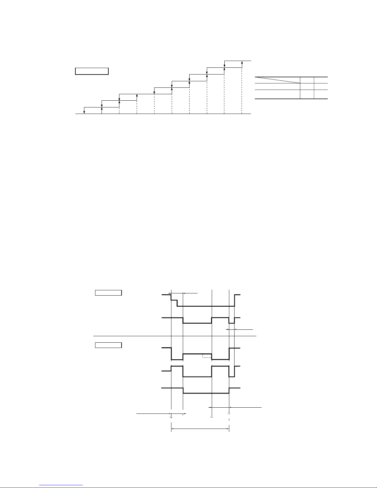
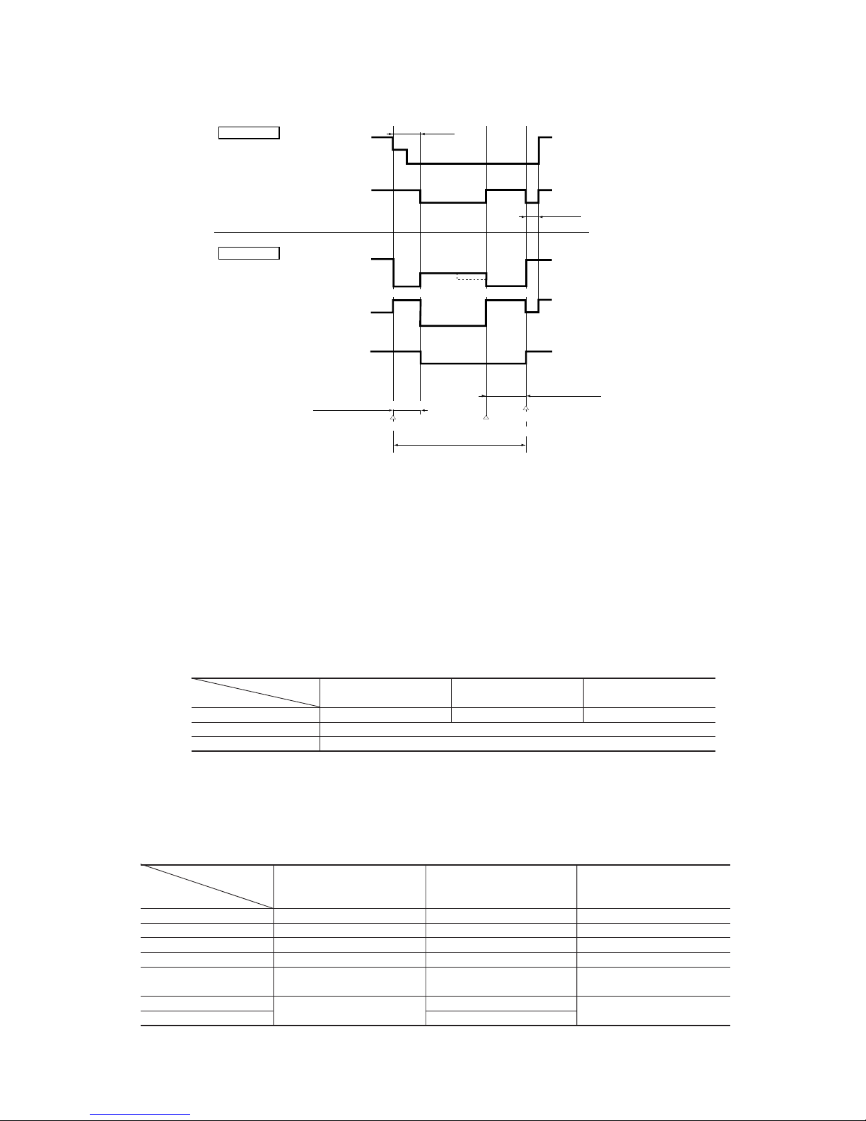
4.6 Comfortable timer setting
If the timer is set at ON when the operation select switch is set at the cooling or heating, or the cooling or heating in auto mode operation
is selected, the comfortable timer starts and determines the starting time of next operation based on the initial value of 15 minutes and the
relationship between the room temperature at the setting time (temperature of room temperature sensor) and the setting temperature.
(Max. 60 minutes)
Operation mode Operation start time correction value (Min.)
3 < Room temp. – Setting temp. 1 < Room temp. – Setting temp. ≤ 3 Room temp. – Setting temp. ≤ 1
At cooling
+5 No change –5
3 < Setting temp. – Room temp. 2 < Setting temp. – Room temp. ≤ 3 Setting temp. – Room temp. ≤ 2
At heating
+5 No change –5
Notes (1) At 5 minutes before the timer ON time, operation starts regardless of the temperature of the room temperature sensor (Th1).
(2) This function does not operate when in the Dry or Auto Dry mode.
However, the operation in item (1) does operate in the Auto Dry mode.
(3) During the comfortable timer operation, both the RUN light and TIMER light illuminate and the TIMER light goes off after expiration of the timer, ON setting
time.
Corrects the starting time of next operation by
calculating the temperature difference.
Operation starting time
Time
Setting time
15 min. 10 min. 5 min.
earlier earlier earlier
¡ If the difference (= Setting temperature – Room tempera-
ture) is 4ºC, the correction value is found to be +5 minutes from the table shown above so that the starting time
of next operation is determined as follows:
15 min. earlier + 5 min. = 20 min. earlier
↑↑
Current operation Correction value
start time
=
=
=
=
Timer operation
(time)
Start
Timer operation
(time)
Temperature
setting (˚C)
Start
Temperature
setting (˚C)
Heating
Cooling, DRY
4.7 Sleep timer operation
Pressing the SLEEP button causes the temperature to be controlled as shown in the following chart with respect to the set temperature.
+
1.0
0
-1.0
0 1.0 2.0
0
-1.0
-2.0
-3.0
-6.0
0 0.5 1.0 2.0
-
16
-
Model
SRK20ZFX-S, 25ZFX-S, 35ZFX-S SRK50ZFX-S
Item
Inverter speed 0rps [Comp. stopped] 10 rps [10sec.] → 0rps [Comp. stopped]
Indoor fan Hot keep normal mode → 1st speed
Outdoor fan Stop 6th speed [1min.] → stop
Flap and louver Horizontal, center
Model
SRK20ZFX-S SRK25ZFX-S SRK35ZFX-S SRK50ZFX-S
Air flow selection
Inverter command speed 30~94rps 30~102rps 20~120rps
Air flow Depends on inverter command speed.
Inverter command speed 30~94rps 30~102rps 20~120rps
Air flow 8th speed fixed
Inverter command speed 30~66rps 30~72rps 30~76rps 20~80rps
Air flow 6th speed fixed
Inverter command speed 30~38rps 30~42rps 30~46rps 20~38rps
Air flow 4th speed fixed
(c) Hot keep operation
If the hot keep operation is selected during the heating operation, the indoor blower is controlled based on the temperature of
the indoor unit heat exchanger (detected with Th2, indoor unit heat exchanger sensor) to prevent blowing of cool wind.
¡ Normal mode (Normal heating operation, operation after HI POWER completion)
Note (1) Refer to the table shown above right for the values A and B.
Indoor heat exchanger temp. (˚C)
¡ Values of A, B
AB
At 0 rps command 22 25
Other than 0 rps
17 19
command
AB
20~35: 23°C
50: 20°C
28 29.5 31.5 34 36 37.5 39 40
1st speed
3rd speed
4th speed
5th speed
6th speed
7th speed
OFF
Indoor fan
4.9 Outline of heating operation
(1) Operation of major functional components in heating mode
(2) Air flow selection
(a) Speed of inverter changes within the range of selected air flow.
(b) When the defrosting, protection device, etc. is actuated, operation is performed in the corresponding mode.
(c) Outdoor unit blower operates in accordance with the inverter command speed.
(3) Details of control at each operation mode (pattern)
(a) Fuzzy operation
Deviation between the room temperature setting correction temperature and the suction air temperature is calculated in
accordance with the fuzzy rule, and used for control of the air capacity and the inverter speed.
(b) Heating thermostat operation
¡ Operating conditions
If the speed obtained with the fuzzy calculation drops below -24 rps during the heating fuzzy operation, the operation
changes to the heating thermostat operation.
¡ Detail of operation
Auto
HI
MED
LO
Item
Indoor fan motor ON ON OFF
Flap and louver ON or OFF ON or OFF Stop position control
Display Lights up Lights up Lights up or flashes
52C ON ON OFF after stop mode
Outdoor fan motor
OFF (20, 25, 35 type)
ON
OFF (20, 25, 35 type)
Depending on the stop mode (50 type) Depending on the stop mode (50 type)
4-way valve
Depending on the stop mode
ON
Depending on the stop mode
Electronic expansion valve Depending on the EEV control
When the inverter
speed is 0rps
When the inverter speed
is other than 0rps
When the inverter speed is 0rps
due to an anomalous stop
Functional
components
8th speed
(20, 25, 35 only)
9th speed
-
17
-
Notes(1) Refer to the table shown above right for the values A and B.
(2) Values in ( ) are for type 20, 25, 35.
¡ Hot keep M mode [During HI POWER operation (for 15 min.)]
Indoor heat exchanger temp. (˚C)
AB2931 32 34 36 43
(40)47(43)
(47)
1st speed
3rd speed
4th speed
5th speed
6th speed
7th speed
OFF
Indoor fan
(d) Defrosting operation
(i) Starting conditions (Defrosting operation can be started only when all of the following conditions are met.)
1 After start of heating operation → When it elapsed 35 minutes. (Accumulated operation time)
2 After end of defrosting operation → When it elapsed 35 minutes. (Accumulated compressor operation time)
3 Outdoor unit heat exchanger sensor (Th4) temperature → When the temperature has been below –5ºC for 3 minutes
continuously.
4 When the temperature difference between the outdoor air sensor temperature and the outdoor unit heat exchanger
sensor temperature exceeded 20. 25 type: 7.0°C, 35 type: 5.0°C, 50 type: 4.0°C
5 During continuous compressor operation
In addition, when the speed command from the indoor controller of the indoor unit during heating operation has
counted 0 rps 10 times or more and all conditions of 1, 2 and 3 above are satisfied (note that when the temperature
for Th4 is -5°C or less: 62 rps or more, -4°C or less: less than 62 rps), defrost operation is started.
(ii) Operation of functional components during defrosting operation
¡ 20, 25, 35 type
Indoor fan
RUN light
Corresponding
to speed
OFF
ON
Flashing
(Hot keep)
Outdoor fan
Inverter
command
Fuzzy calculated
value
70 rps
0
Corresponding
to speed
OFF
OFF
ON
(1)
4-way valve
Final defrost operation
Defrost control
Hot keep
Indoor unit
Outdoor unit
60 sec.
Hot keep
50 sec.
Normal heating operation restored
Defrost end
(Th4
>
=
13˚C, 10 minutes)
Defrost operation
Defrost operation
preparation
6th speed 6th speed
¡ Values of A, B
AB
At 0 rps command 22 25
Other than 0 rps
17 19
command
8th speed
9th speed
(20, 25, 35 type only)
Note (1) When outdoor unit heat exchanger sensor (Th4) temperature becomes 2°C or higher, inverter command changes 70 rps to 50 rps.
-
18
-
(iii) Ending conditions (Operation returns to the heating cycle when either one of the following is met.)
1 Outdoor heat exchanger sensor (Th4) temperature: 13ºC or higher (50 type: 13°C or higher) for 30 seconds
continuously
2 Continued operation time of defrosting → For more than 10 min.
(e) Heating “HIGH POWER” operation (HI POWER button on remote control: ON)
Operation is maintained for 15 minutes with a higher blow out air temperature.
¡ Detail of operation
Model
SRK20ZFX-S SRK25, 35ZFX-S SRK50ZFX-S
Item
Inverter speed 94 rps 102 rps 120 rps
Indoor fan Hot keep M mode (max 8th speed)
Outdoor fan 6th speed
Notes (1) Room temperature is not adjusted during the HIGH POWER operation.
(2) Protective functions will actuate with priority even during the HIGH POWER operation.
Indoor fan
RUN light
Corresponding
to speed
OFF
ON
Flashing
(Hot keep)
Outdoor fan
Inverter
command
Fuzzy calculated
value
70 rps
(1)
0
Corresponding
to speed
OFF
OFF
ON
4-way valve
Final defrost operation
Defrost control
Hot keep
Indoor unit
Outdoor unit
75 sec.
Hot keep
60 sec.
Normal heating operation restored
Defrost end
(Th4
>
=
13°C, 10 minutes)
Defrost operation
Defrost operation
preparation
6th speed
6th speed
4.10 Outline of cooling operation
(1) Operation of major functional components in cooling mode
¡ 50 type
Item
Indoor fan motor ON ON OFF
Flap and louver ON or OFF ON or OFF Stop position control
Display Lights up Lights up Lights up or flashes
52C ON ON OFF after stop mode
Outdoor fan motor
OFF (20, 25, 35 type)
ON
OFF (20, 25, 35 type)
Depending on the stop mode (50 type) Depending on the stop mode (50 type)
4-way valve
Depending on the stop mode
ON
Depending on the stop mode
Electronic expansion valve Depending on the EEV control
When the inverter
speed is 0rps
When the inverter speed
is other than 0rps
When the inverter speed is 0rps
due to an anomalous stop
Functional
components
Note (1) When outdoor unit heat exchanger sensor (Th4) temperature becomes 7°C or higher, inverter instruction changes 70 rps to 50 rps.
-
19
-
(2) Air flow selection
(a) Speed of inverter changes within the range of selected air flow.
(b) When any protective function actuates, the operation is performed in the mode corresponding to the function.
(c) Outdoor blower is operated in accordance with the inverter command speed.
(3) Detail of control in each mode (Pattern)
(a) Fuzzy operation
During the fuzzy operation, the air flow and the inverter speed are controlled by calculating the difference between the room
temperature setting correction temperature and the suction air temperature.
(b) Cooling thermostat operation
(i) Operating conditions
During the cooling fuzzy operation or when the speed obtained by the fuzzy calculation is less than -24 rps.
(ii) Detail of operation
Model
SRK20ZFX-S SRK25ZFX-S SRK35ZFX-S SRK50ZFX-S
Item
Inverter speed 65 rps 74 rps 86 rps 92 rps
Indoor fan 7th speed
Outdoor fan 6th speed
Model
SRK20ZFX-S SRK25ZFX-S SRK35ZFX-S SRK50ZFX-S
Air flow selection
Inverter command speed 20~65rps 20~74rps 20~86rps 20~92rps
Air flow Depends on inverter command speed.
Inverter command speed 20~65rps 20~74rps 20~86rps 20~92rps
Air flow 7th speed fixed
Inverter command speed 20~44rps 20~56rps 20~58rps 20~62rps
Air flow 5th speed fixed
Inverter command speed 20~30rps 20~34rps 20~38rps 20~30rps
Air flow 2nd speed fixed
(c) Cooling “HIGH POWER” operation (HI POWER button on remote control: ON)
The unit is operated continuously for 15 minutes regardless of the setting temperature.
1) Detail of operation
Model
SRK20ZFX-S, 25ZFX-S, 35ZFX-S SRK50ZFX-S
Item
Inverter speed 0 rps [Comp. stopped] 10rps [10sec.] → 0rps [Comp. stopped]
Indoor fan Corresponds to fan speed switch.
Outdoor fan Stop 6th speed [1min.] → stop
Notes (1) Protective functions will actuate with priority even during the “HIGH POWER” operation.
(2) Room temperature is not adjusted during the “HIGH POWER” operation
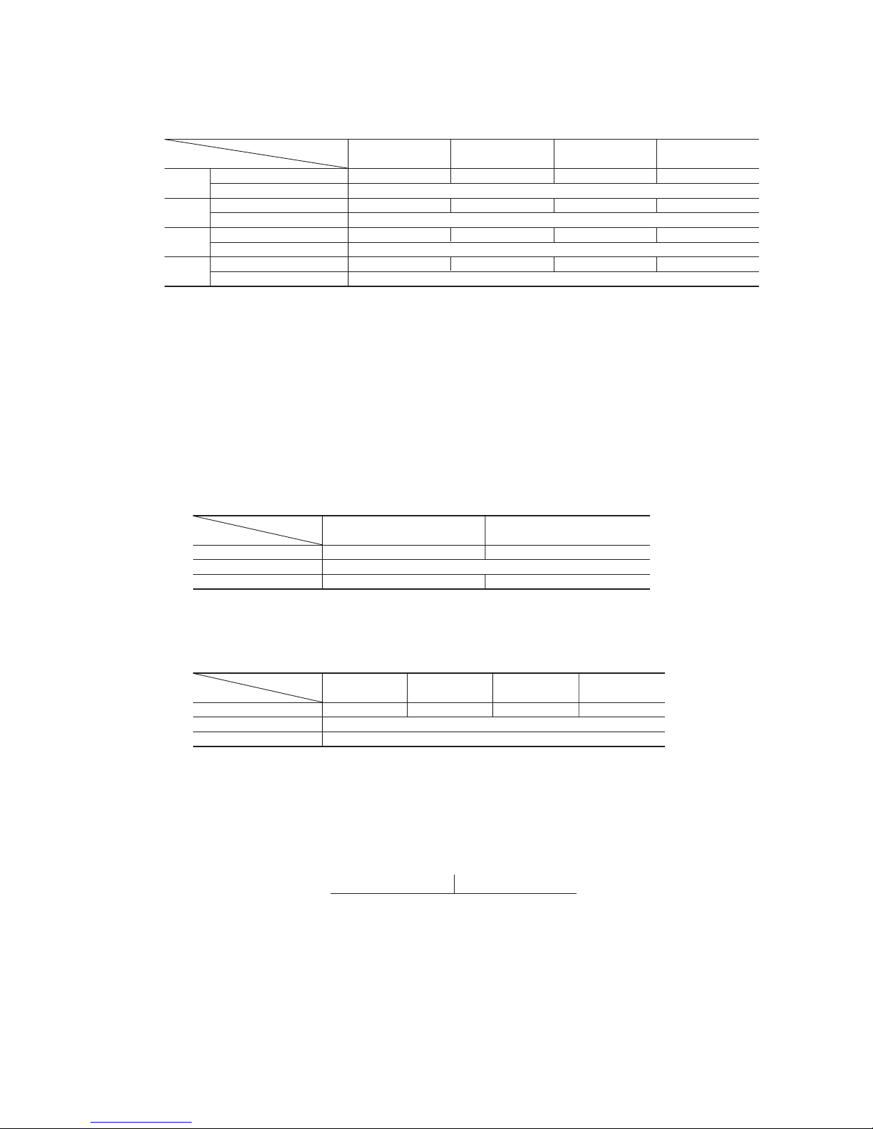
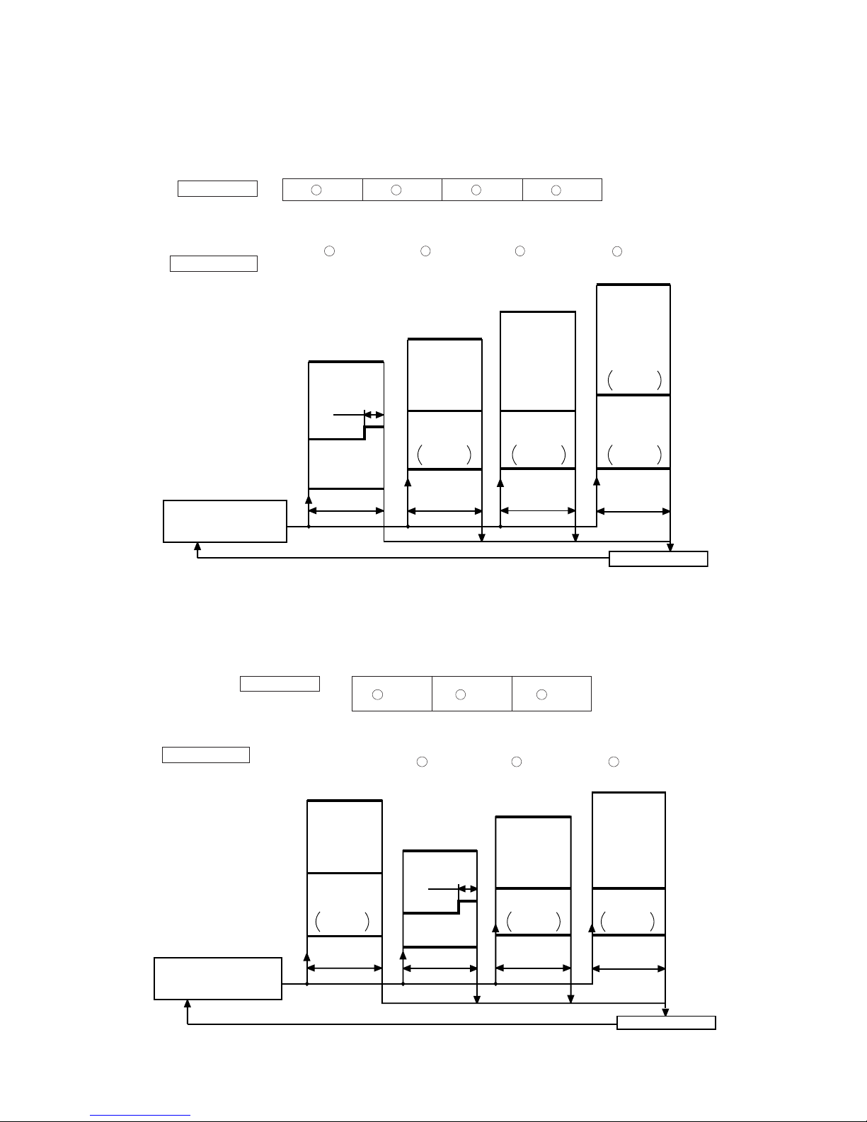
4.11 Outline of dehumidifying operation
(1) After operating the indoor blower for 20 seconds from immediately after the start of operation, the indoor temperature is checked
and, based on the result of check, the cooling oriented dehumidifying or heating oriented dehumidifying is selected.
Heating oriented dehumidifying Cooling oriented dehumidifying
Low –3 High
Room temperature - Setting temperature (deg)
Cooling or heating oriented dehumidifying is selected again one hour after the first selection of the cooling or heating oriented
dehumidifying.
Auto
HI
MED
LO
-
20
-
D range C range B range A range
(b) Heating oriented dehumidifying
After interrupting the compressor operation for 3 minutes (by the 3-minute timer) following the determination of heating
oriented dehumidifying, the unit begins in the heating operation. If the room temperature exceeds the setting temperature by
2ºC or more, the unit checks the room temperature at 5-minute intervals and, depending on the result, determines the range
of heating oriented dehumidifying operation.
Operation range
D C B A
Low –1 0 +2 High
Room temperature – Setting temperature (deg)
(D) (C) (C) (B)
OFF
5th speed
25 sec.
OFF
0
20, 25, 35 type : 38
50 type : 24
20, 25, 35 type : 50
50 type : 40
50 type :
4th speed
20, 25, 35 type : 30
50 type : 20
5th speed
2nd speed
1st speed
50 type :
4th speed
50 type :
4th speed
50 type :
4th speed
Inverter speed
Indoor fan
Outdoor fan
Determination of cooling
oriented dehumidifying
operation range
Temperature check
5 min. 5 min. 5 min. 5 min.
Operation pattern
O L M
Low –1 0 High
Room temperature – Setting temperature (deg)
Operation range
Heating operation O range L range M range
4th speed
OFF
OFF
4th speed
2nd speed
1st speed
20, 25, 35 type : 38
50 type : 28
20, 25, 35 type : 30
50 type : 20
20, 25, 35 type : 48
50 type : 44
0
50 type :
4th speed
50 type :
4th speed
25 sec.
50 type :
4th speed
5th speed
Inverter speed
Indoor fan
Outdoor fan
Determination of heating
oriented dehumidifying
operation range
Temperature check
5 min. 5 min. 5 min.
Depends on
the operation
condition
Operation pattern
Note (1) Figures in the parentheses
( ) show the values at
ECONOMY operation.
Note (1) Figures in the parentheses
( ) show the values at
ECONOMY operation.
(2) Outline of control
(a) Cooling oriented dehumidifying
Room temperature is checked at 5-minute intervals after selecting the cooling or heating oriented dehumidifying in order to
determine the operation range.
(O) (L) (L)
-
21
-
4.12 Outline of automatic operation
(1) Determination of operation mode
The unit checks the room temperature and the outdoor air temperature after operating the indoor and outdoor blowers for 20
seconds, determines the operation mode and the room temperature setting correction value, and then begins in the automatic
operation.
Heating
Dehumidifying
Cooling
Room temperature (˚C)
Outdoor temperature (˚C)
27.5
25.5
19.5
18
30
(2) The unit checks the temperature every hour after the start of operation and, if the result of check is not same as the previous
operation mode, changes the operation mode.
(3) When the unit is started again within one hour after the stop of automatic operation or when the automatic operation is selected
during heating, cooling or dehumidifying operation, the unit is operated in the previous operation mode.
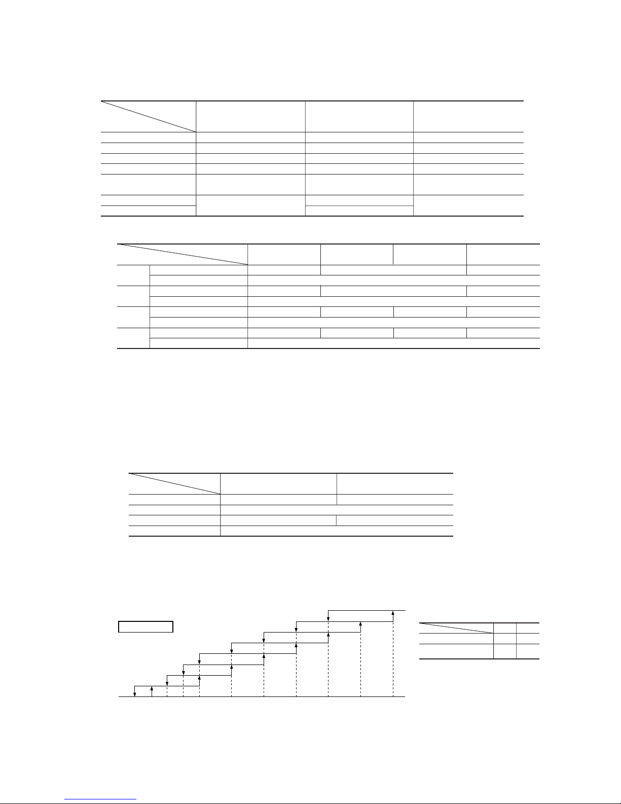
(4) Setting temperature can be adjusted within the following range. There is the relationship as shown below between the signals of
the wireless remote control and the setting temperature.
Signals of wireless remote control (Display)
–6 –5 –4 –3 –2 –1 ±0+1+2+3+4+5+6
Setting
Cooling 19 20 21 22 23 24 25 26 27 28 29 30 31
temperature
Dehumidifying 19 20 21 22 23 24 25 26 27 28 29 30 31
Heating 20 21 22 23 24 25 26 27 28 29 30 31 32
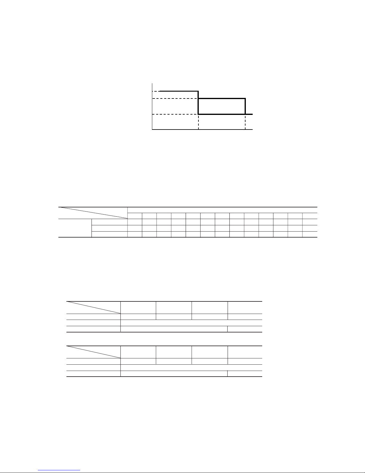
4.13 ECONOMY operation
(ECONO button on remote control: ON)
(1) The set temperature is raised by 1.5ºC (0.5ºC every one hour) at cooling operation and lowered by 2.5ºC (Steps of 1ºC, 1ºC and
0.5ºC every one hour) at heating operation to continue the operation with the following contents.
(2) Detail of operation
◆ Heating
◆ Cooling
Model
SRK20ZFX-S SRK25ZFX-S SRK35ZFX-S SRK50ZFX-S
Item
Inverter command speed 30~66rps 30~72rps 30~76rps 20~66rps
Indoor fan 4th, 6th speed
Outdoor fan 5th speed 4th, 5th speed
Model
SRK20ZFX-S SRK25ZFX-S SRK35ZFX-S SRK50ZFX-S
Item
Inverter command speed 20~42rps 20~52rps 20~58rps 20~42rps
Indoor fan 2nd, 5th speed
Outdoor fan 5th speed 4th speed
 Loading...