

Mitsubishi Heavy Industries SRK25QA-S, SRK35QA-S, SRC25QA-S, SRC35QA-S Technical Manual

-1-
Mitsubishi Heavy Industries Air Conditioners
Technical Manual
Manual Number: 2011 No. W1-01
Variable Frequency Wall Mounted Type
Room Air Conditioners
(Split system, heat pump type)
SRK25QA-S/SRC25QA-S
SRK35QA-S/SRC35QA-S
(R410A Refrigerant Used)
MITSUBISHI HEAVY INDUSTRIES, LTD.

-2-
Table of Contents
1. GENERAL INFORMATION……..…………………………….……1
1.1 Features…………………………………………………………..…1
1.2 Model identification………………………………………………1
2 MODEL SELECTION…………………………………………………2
2.1 Model function..…………..…….……..………………………..……2
2.2 Range of usage……………………………………………..………4
2.3 Outline drawing…..………………………………………………..…4
2.4 Cooling cycle system diagram….…………………..…………...…5
2.5 Performance curve……………………………………………………6
3 ELECTRICAL WIRING DIAGRAM………………………………….7
4 NAME OF EACH PART AND ITS FUNCTION……………….….….9
4.1 NAME OF EACH PART………………..………….………………9
4.2 Emergency “ON/OFF” button (back-up switch) …........………..12
4.3 Automatic restart……………..…………..………………………..12
4.4 Flap control………..…………..……..……………………………..12
4.5 Comfort timer setting……..……..……..…………………………..14
4.6 Outline of heating operation.……..………………………….……..15
4.7 Outline of cooling operation ............................................................ 17
4.8 Outline of drying operation ................................................. 18
4.9 Outline of automatic operation ..........................................................20
4.10 Economical operation.....................................................................20
4.11 Air blowing operation.......................................................................20
4.12 CLEAN operation control...................................................21
4.13 EEV control.....................................................................................21
5 INSTALLATION................................................................................22
5.1 Selection of installation location.................................................24
5.2 Installation of indoor unit..................................................................25
5.3 Installation of outdoor unit...............................................................28

-3-
5.4 Pipe connection.................................................................................28
5.5 Precautions for wireless remote controller operation........................30
5.6 Standard running data........................................................................31
6 MAINTENANCE................................................................................32
6.1 Electrical parts failure diagnosis method............................................32
6.2 Servicing.............................................................................................56
7 SERVICING MANUAL.......................................................................57
8 MOUNT ASSEMBLY………………………….................................72
8.1 Indoor unit.........................................................................................72
8.2 Outdoor unit......................................................................................80

-1-
1 GENERAL INFORMATION
1.1 Features
(1) Inverter
● Heating/cooling
The rotate speed of the compressor is changed steplessly in relation to varying load, and is
linked with the fans of indoor and outdoor units controlled by the changes of frequency, thus
controls the power.
● Allowing quick heating/cooling operation during start-up period.
The room temperature is kept constant through fine-tuned control after the machine is
stabilized.
(2) Fuzzy control: According to the fuzzy control technology, the room temperature and humidity,
etc. are obtained through dynamic analysis to accurately regulate the rotate
speeds of the compressor and the fan to realize precise temperature control.
(3) Life: Actual service life: over 20,000 hours; Working life: over 100,000 hours; On/off of relay:
over 100,000 times; Continuous on of LED: over 50,000 hours; On/off of emergency
switch: over 10,000 times.
(4) Self diagnosis function: We will continuously provide the best services for our customers
through devices judging abnormal operation, as follows:
The air conditioner indicates the error of the indoor and outdoor sensors (thermistors) only when
it is in the stop mode. Error indication is removed after restart.
1.2 Model identification
R410A Refrigerant used
Master pattern change code
Master pattern
Capacity
Wall mounted type (C is the code for outdoor unit.)
Split type room air conditioner
TIMER lamp
ON
RUN lamp
keeps flashing
RUN lamp
ON
RUN lamp
Flash 2 times
RUN lamp
Flash 1 time
Flash 2 times
Flash 5 times
Flash 6 times
TIMER lamp
Flash 1 time
Flash 2 times
Flash 4 times
Flash 1 time
Flash 2 times
Flash 3 times
Flash 4 times
Flash 5 times
Flash 6 times
Flash 2 times
Failure Causes
Heat exchanger sensor error
Room temperature sensor error
Abnormal voltage input
Indoor fan motor error
Outdoor unit temperature sensor
error
Outdoor unit heat exchanger liquid
pipe sensor error
Vent-pipe sensor error
Current cut
Outdoor unit error
Safe current
Power transistor error
Compressor over heat protection
Signal transmission error
Rotor lock
Heat exchanger sensor wire break, poor connector connection
Room temperature sensor wire break, poor connector connection
Voltage too high or too low
Failure of fan motor, poor connector connection
Outdoor unit sensor wire break, poor connector connection
Heat exchanger liquid pipe sensor wire break, poor connector
connection
Vent-pipe sensor wire break, poor connector connection
Compressor blockage, compressor output open-phase, power short
circuit, control valve closed
Power-cut, compressor wire break
Vent-pipe sensor wire break, poor connector connection
Compressor not rotating (dead lock)
Overload, over current
Failure of power transistor
Insufficient refrigerant, failure of vent-pipe sensor, control valve
closed
Failure of power supply, signal cable break, failure of
indoor/outdoor unit control device
Failure of compressor
Compressor open-phase
Failure of outdoor unit control device
-2-
2 MODEL SELECTION
2.1 Model function
2.1.1 Model: SRK25QA–S (Indoor unit)
SRC25QA–S (Outdoor unit)
Item
Unit
Indoor unit SRK25QA–S
Outdoor unit SRC25QA–S
Net weight
kg
9
31
Machine
dimension
mm
790×222×268
780×290×540
Package
dimension
Length× Width
×Height
830×340×280
920×380×590
Color White
Ash-colored
Fan
Through-flow type, AS resin + glass
fiber
Axial flow type, AS resin + glass
fiber
Air flow
m3/h
550
1830
Noise in cool
room
dB(A)
Hi/Me/Lo:
37/30/23(completely mute,
SPL)
45(completely mute, SPL)
Noise in warm
room
dB(A)
Hi/Me/Lo:
37/32/28(completely mute,
SPL)
48(completely mute, SPL)
Fan motor
Nominal value
16W, 4-step capacitor type
asynchronous motor, insulation
grade E
25W, AC motor, insulation grade B
Power of motor
W (reference
value)
40
50
Power of electric
control
W (reference
value)
2
7.5
Power supply and
power cord
Single-phase, 220V, 50Hz and 3-core, 1.0mm2, 250V, 10A, 2m, w/o plug
Heat exchanger
Spiral, hydrophilic, 3-folded,
16-section, 2-row, 452-fin, 1-2
circuit
Spiral, hydrophilic, 20-section,
1-row, 621-fin, 2-1 circuit
Compressor
Nominal value
THACOM RM - B5077MDE2, 527W, DC frequency conversion
compressor, insulation grade E
Refrigerating
machine oil
ml
300, DIAMOND FREEZE MA68
Refrigerant
controller
Electronic expansion valve (Φ1.65mm) + hush pipe
Refrigerant
g
R-410A, 850g, addition/reduction not needed within the use range of 15m
Operating
pressure limit
Mpa
Max.: 4.1, Min.: 1.47
Air filter
Mould-proof air filter
Accessories and
quantity
Indoor unit 1, mounting plate 1, tapping screw 5, battery 2, use and
installation manual 1, remote controller 1, outdoor unit 1, Drain elbow 1,
Water shutoff plug 1
Operation control
devices
Wireless remote controller, electronic thermostat controlling room
temperature, microcomputer controlling defrosting
Safety devices
Serial signal protection, fan error protection, compressor over heat
protection, high voltage protection, over current protection, etc.
* The nominal values of “Noise in cool room” and “Noise in warm room” in the above table are tested in a dead
room.
Item
Unit
Rating cooling
Rating heating
Capacity
W
2500
3200
Power
W
700
870
Energy efficiency ratio
3.57
3.68
Energy efficiency grade
Grade A (European norm)
Note (1) The data are measured at the following conditions. The pipe length is 5m.
Item
Operation
Indoor air temperature
Outdoor air temperature
Standards
DB
WB
DB
WB
Cooling
27℃
19℃
35℃
24℃
Heating
20℃
—
7℃
6℃
Low temperature Heating
20℃ — 2℃
1℃
(2) The operation data are applied to the 220Vdistricts respectively.
(3) The refrigerant quantity to be charged includes the refrigerant in 15m connecting piping.
(Purging is not required even for the short piping.)
-3-
2.1.2 Model: SRK35QA–S (Indoor unit)
SRC35QA–S (Outdoor unit)
Item
Unit
Indoor unit SRK35QA–S
Outdoor unit SRC35QA–S
Net weight
kg
9.5
35
Machine
dimension
mm
790×222×268
780×290×540
Package
dimension
Length× Width
×Height
830×340×280
920×380×590
Color White
Ash-colored
Fan
Through-flow type, AS resin + glass
fiber
Axial flow type, AS resin + glass
fiber (embedded damping spindle
sleeve)
Air flow
m3/h
520
1940
Noise in cool
room
dB(A)
Hi/Me/Lo: 40/33/25
47
Noise in warm
room
dB(A)
Hi/Me/Lo: 39/35/27
48
Fan motor
Nominal value
16W, 4-step capacitor type
asynchronous motor, insulation
grade E
24W, DC motor, insulation grade E
Power of motor
W (reference
value)
40
20
Power of electric
control
W (reference
value)
2
7.5
Power supply and
power cord
Single-phase, 220V, 50Hz and 3-core, 1.0mm2, 250V, 10A, 2m, w/o plug
Heat exchanger
Spiral, hydrophilic, 3-folded,
16-section, 2-row, 452-fin, 1-4
circuit
Child heat exchanger: Spiral,
hydrophilic, 1-row, 4-section,
408-fin
Spiral, hydrophilic, 20-section,
2-row, 1221-fin, 2-1 circuit
Pf1.4
Compressor
Nominal value
THACOM RM - B5077MDE2, 527W, DC frequency conversion
compressor, insulation grade E
Refrigerating
machine oil
ml
300, DIAMOND FREEZE MA68
Refrigerant
controller
Electronic expansion valve (Φ1.5mm) + hush pipe
Refrigerant
g
R-410A, 900g, addition/reduction not needed within the use range of 15m
Operating
pressure limit
MPa
Max.: 4.15, Min.: 1.47
Air filter
Mould-proof air filter
Accessories and
quantity
Indoor unit 1, mounting plate 1, tapping screw 5, battery 2, use and
installation manual 1, remote controller 1, outdoor unit 1, Drain elbow 1,
Water shutoff plug 1
Operation control
devices
Wireless remote controller, electronic thermostat controlling room
temperature, microcomputer controlling defrosting
Safety devices
Serial signal protection, fan error protection, compressor over heat
protection, high voltage protection, over current protection, etc.
* The nominal values of “Noise in cool room” and “Noise in warm room” in the above table are tested in a dead
room.
Item
Unit
Rating cooling
Rating heating
Capacity
W
3500
4000
Power
W
1020
1100
Energy efficiency ratio
3.43
3.64
Energy efficiency grade
Grade A (European norm)
Note (1) The data are measured at the following conditions. The pipe length is 5m.
Item
Operation
Indoor air temperature
Outdoor air temperature
Standards
DB
WB
DB
WB
Cooling
27℃
19℃
35℃
24℃
Heating
20℃
—
7℃
6℃
Low temperature Heating
20℃ — 2℃
1℃
(2) The operation data are applied to the 220Vdistricts respectively.
(3) The refrigerant quantity to be charged includes the refrigerant in 15m connecting piping.
-4-
(Purging is not required even for the short piping.)
2.2 Range of usage
Please use the air conditioners within the following range of usage, otherwise the protector will be
triggered.
Cooling Operation
Heating Operation
Outdoor temperature
About 18℃~43℃
About -15~24℃
Room temperature
About18℃~32℃
About below 30℃
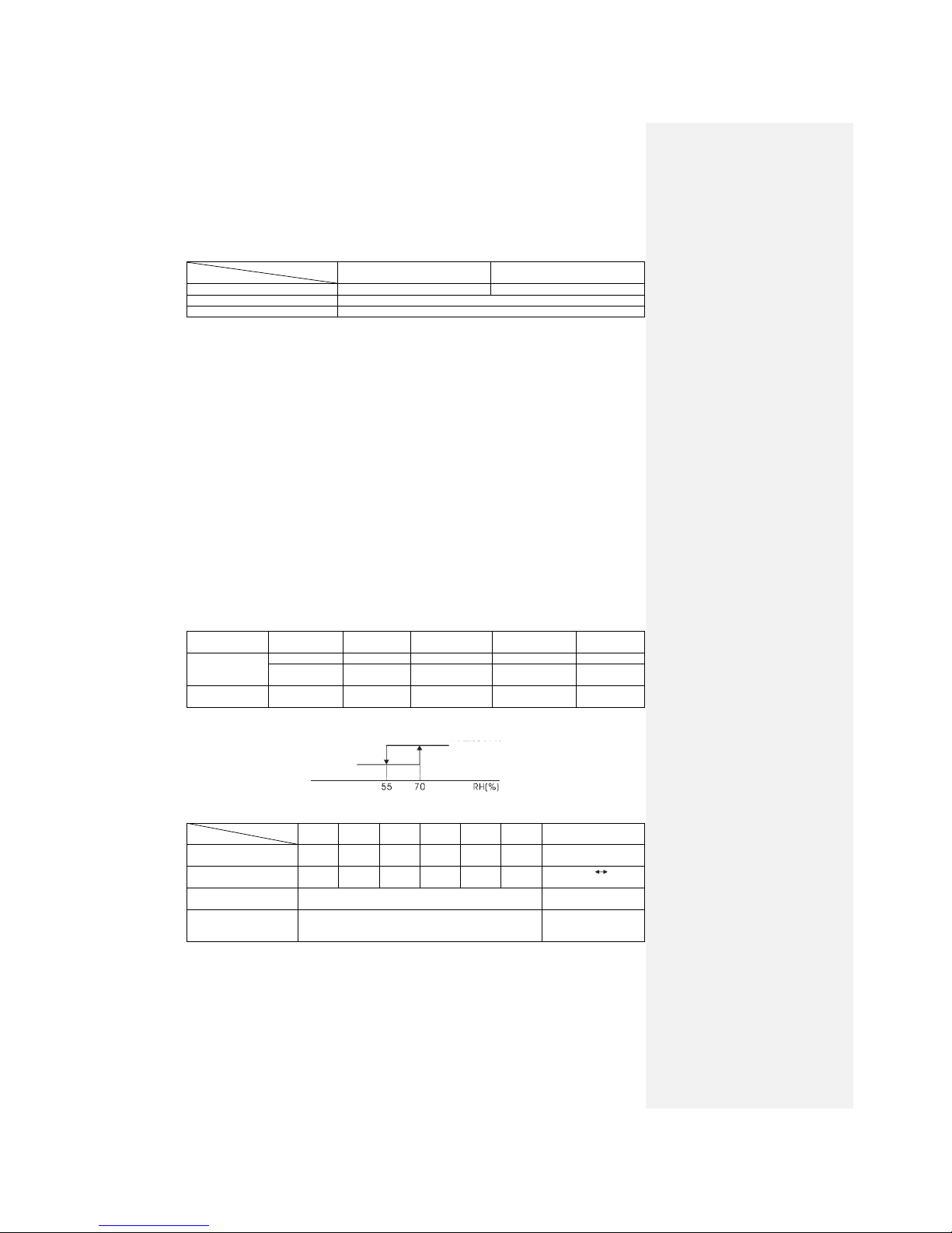
Indoor humidity
About below 80%
25~35 Models
Max. piping one-way length
Within 15 m
Vertical height difference
Within 5 m
Additional R410A Refrigerant
Not required
Voltage
Rating ±10%
Starting voltage
At least 85% of rating
Switching frequency
Max. 10 times per hour
Time interval between stop and start
Min. 3 min
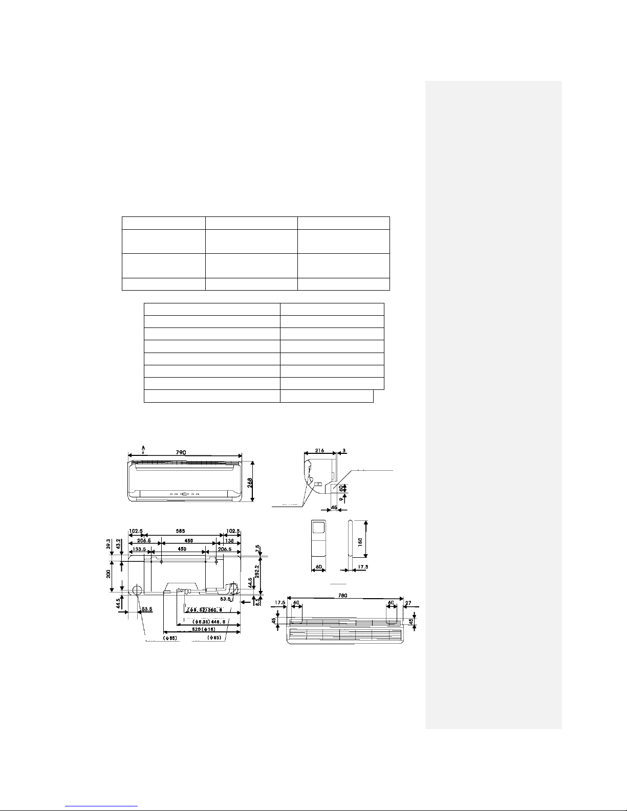
2.3 Outline drawing
(1) Indoor unit: SRK25QA–S/ SRK35QA–S Unit: mm
Piping hole right (left)
Terminal block
Remote controller
Flare connecting (Gas)
Flare connecting (Liquid)
Drainage pipe
Piping hole
Piping hole
VIEW A
-5-
(2) Outdoor unit: SRC25QA-S/ SRC35QA-S Unit: mm
2.4 Cooling cycle system diagram
Models: QA-S Series
Note (1)……line is piping for site construction.
Drain holes
Terminal block
Flare connecting
Flare connecting
Operation valve (Gas)
Indoor unit
Outdoor unit
Circulation of cooling
Circulation of heating
Flare connecting
Operation valve (Gas)
Outdoor air
temp. sensor
Air heat
exchanger
Heat exchanger
sensor
Gas liquid
separator
Compressor
Discharge pipe sensor
4-way valve
Check joint
Gas pipe Note (1)
model
Air heat
exchanger
Inlet air temp.
sensor
Air heat
exchanger sensor
Liquid pipe
Flare connecting
Filter
Electronic expansion valve
Hush pipe
Hush pipe
Operation valve (Liquid)
Refrigerant inlet pipe
Refrigerant outlet
pipe
-6-
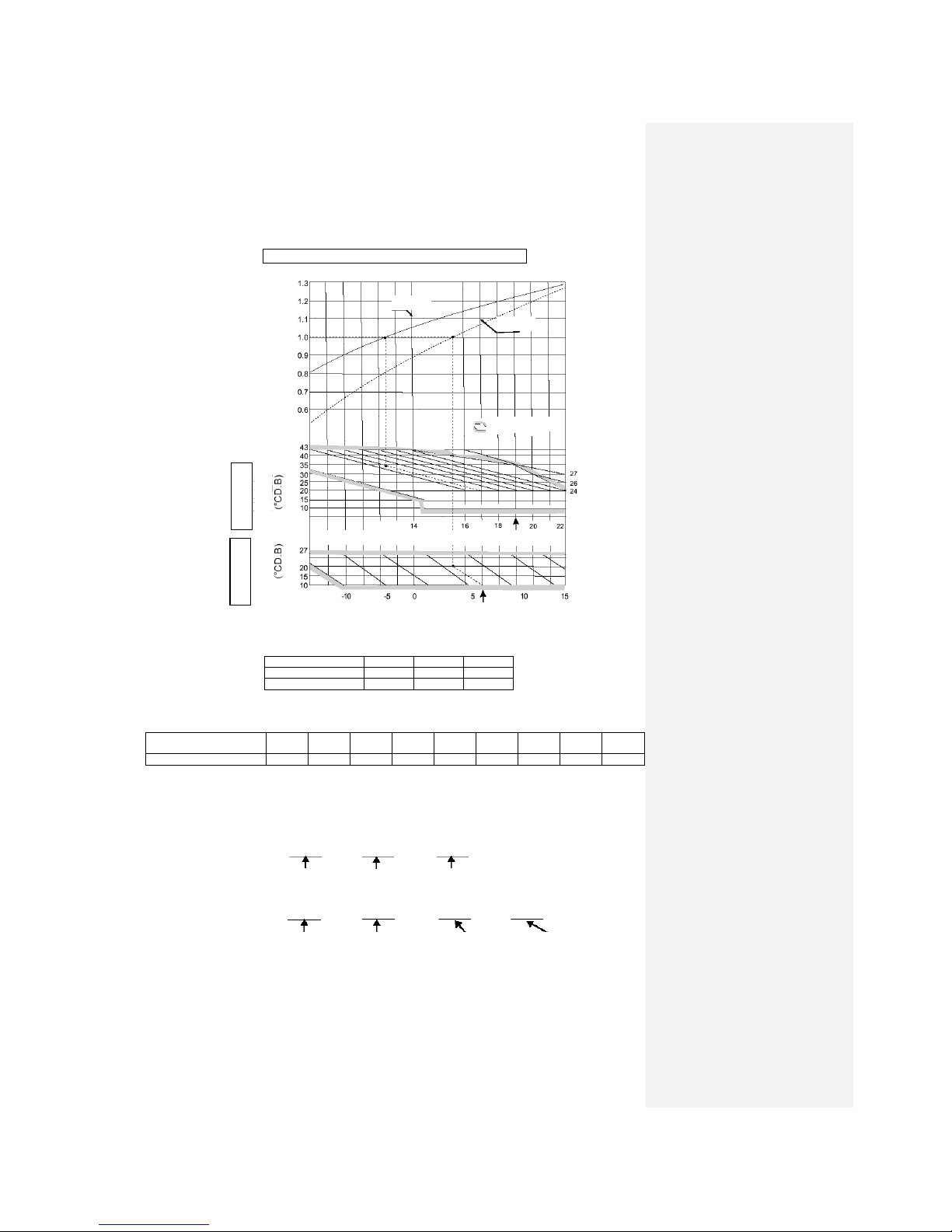
2.5 Performance curve
The cooling and heating capacities are measured in the following conditions. The actual capacity
can be obtained with the following formula.
Actual capacity = Rating capacity x Correction factor
(1) Capacity correction according to indoor and outdoor temperatures:
Outdoor air W.B. temperature (°C W.B.) ISO-T1 Standard
⑵ Capacity correction according to one way length of refrigerant piping:
It is necessary to correct the cooling and heating capacity according to the one way length of
refrigerant piping.
Piping length (m)
7
10
15
Cooling
1.0
0.99
0.975
Heating
1.0
1.0
1.0
⑶ Capacity correction according to frosting on outdoor heat exchanger during heating:
In additions to the foregoing corrections (1) and (2), the heating capacity also needs to be
corrected according to the frosting on the outdoor heat exchanger.
Air inlet temperature of
outdoor unit
-10
-9
-7
-5
-3
-1 1 3
5
Frosting correction factor
0.95
0.94
0.93
0.91
0.88
0.86
0.87
0.92
1.00
⑷ Example of cooling and heating capacity calculation:
The actual cooling capacity of model SRK25QA-S with the one way piping length of 25m at the
indoor wet-bulb temperature of 19℃ and outdoor dry-bulb temperature of 35℃in summer or
indoor dry-bulb temperature of 20℃, outdoor dry-bulb temperature of 1℃and indoor wet-bulb
temperature of -1℃ in winter is
Actual cooling capacity = 2500 x 1.0 x 0.95 ≈ 2375W
Nominal cooling Temp. correction Piping length
capacity factor correction factor
Actual heating capacity = 3200 x 0.81 x 0.95 x 0.86 ≈ 2118W
Nominal heating Temp. correction Piping length Frosting
capacity factor correction factor correction factor
Cooling
Heating
Accommodation
Cooling operation
Heating operation
Indoor air D.B.
temperature
Outdoor air D.B.
temperature
Indoor air W.B. temperature (°C W.B.) ISO-T1 Standard
Correction factor of cooling & heating
capacity in relation to temperature
-7-
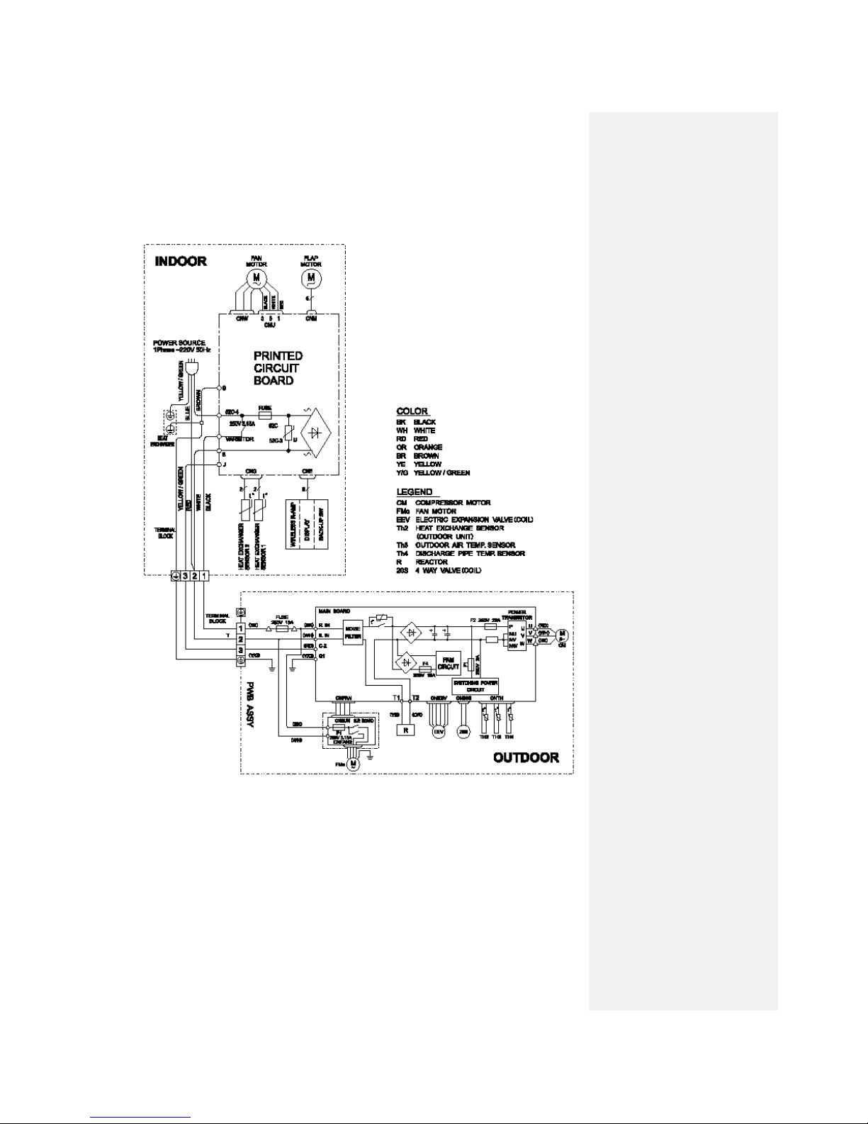
3 ELECTRICAL WIRING DIAGRAM
3.1 Circuit diagram: 25QA-S
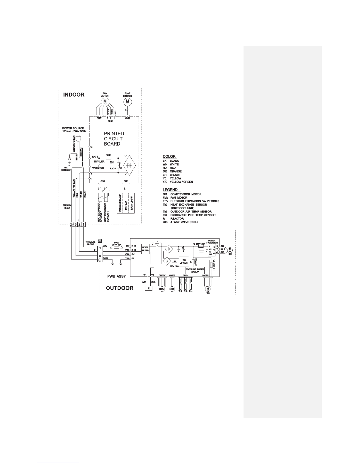
-8-
3.2 Circuit diagram: 35QA-S
-9-
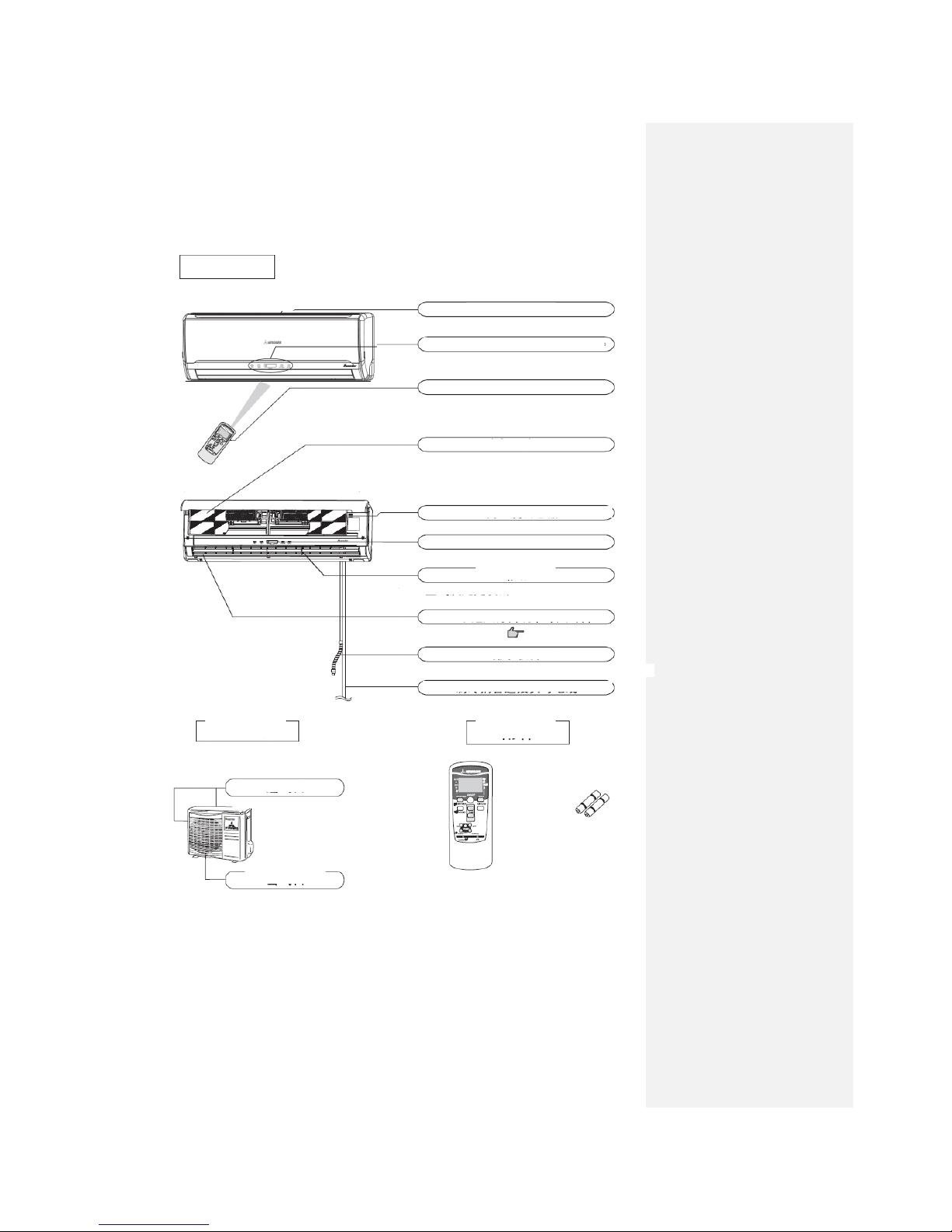
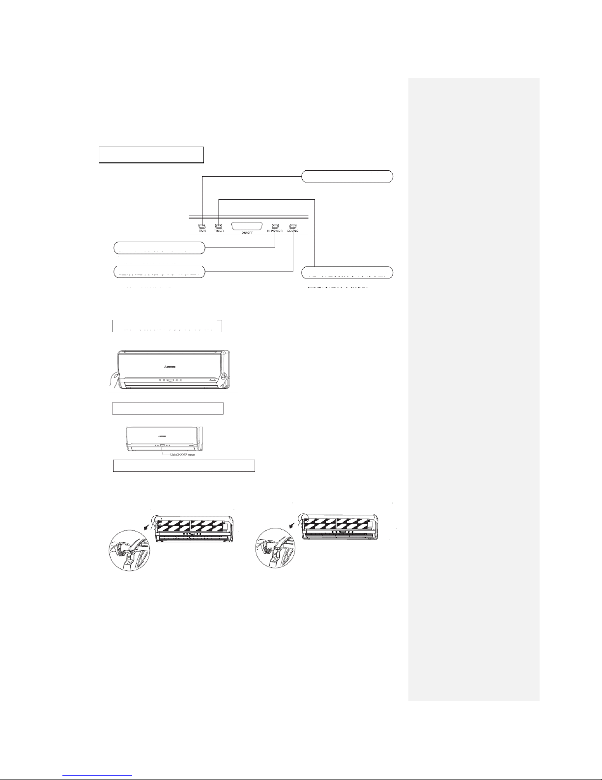
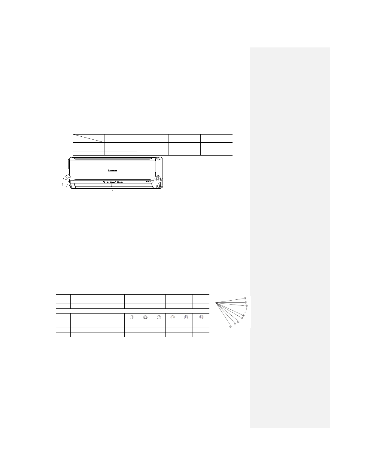
4 NAME OF EACH PART AND ITS FUNCTION
4.1 Name of each part
Indoor unit
Air inlet panel
Draws in the indoor air.
Unit indication section and remote control signal receiver
Wireless remote control
Air filter
Removes dust or dirt from the inlet air
Room temperature detector
Unit operation switch
Air blows from here.
Up/down air direction flap
Page 11
Drain hose
Drains water from the dehumidified air.
Refrigerant piping connection electric flex
Outdoor unit
Accessories
Air inlet
Air out
(on side&rear suface)
Battery
Wireless remote controller
Air outlet
-10-
Indication section of air conditioner
RUN lamp (green)
ON during running and
mould-proof running
TIMER lamp (yellow)
ON during timing operation
HI POWER lamp (green)
ON during Hi Power running
Opening the air inlet grille
Put your hands on the indentations on both sides, raise the grille towards yourself, and stop at the
opening position of about 60°.
Closing the air inlet grille
Gently push both sides and then gently push the central portion.
Removing and mounting the air inlet grille
To remove the air inlet grille to clean the inside,
open it at the position of about 65° and pull it
towards yourself to remove the grille.
To mount the air inlet grille, insert the mounting
arm in the pin roll on the main frame and close the
grille.
ECONO lamp (green)
ON during ECONO running
-11-
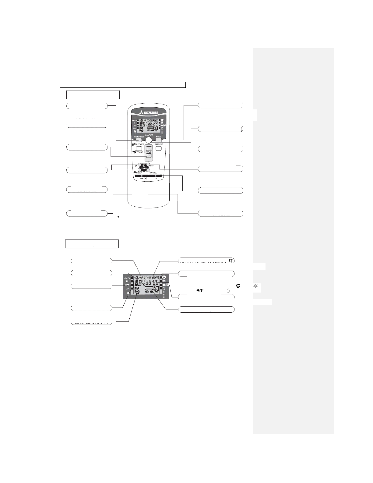
Operation and indication section for remote control
Operation section
FAN SPEED button
Each time the button is pushed ■indicator is
switched over in turn.
HI POWER/ECONOMY button
TEMPERATURE button
This button sets the room temperature.(press the button to select the
current time and timing time)
ON TIMER button
This button sets the ON timer Times.
CLEAN button
Indication section
SLEEP indicator
Indicates during SLEEP mode
TEMPERATURE indicator
FAN SPEED indicator
Indicates set air flow rate with■ lamp.
HI POWER/ECONOMY indicator
Display in the HI POWER/ ECONOMY operation mode respectively.
OPERATION MODE select button
Each time the button is pushed ■
indicator is switched over in turn.
ON/OFF button
Press for starting operation press again for stopping.
AIR FLOW button
This button sets the swaying
OFF TIMER button
CANCEL button
The button is used to cancel the timing
ONtimer/OFF timer and SLEEP operation.
Indicates during ON/OFF TIMER mode operation.
Operation mode indicator
Indicates selected operation with lamp.
Time display lamp
Display the current time or the time
■ is used to indicate the mode selected: [ (AUTO)
(COOLING) (HEATING) (DRYING)]
Display the swaying way of the wind guide blade.
The above illustration shows all
controls,but in practice only the
relevant parts are shown.
CLEAN indicator
ON/OFF (luminous) button
This button changes the HI POWER /ECONOMY mode.
SLEEP button
This button changes the
“SLEEP” mode.
This button changes the “CLEAN” mode.
RESET switch
Switch for resetting microcomputer.
This button sets the OFF timer
Times.
Indicates set temperature.
(Does not indicate temperature
when operation mode is on AUTO)
Air supply display lamp
-12-
4.2 Emergency “ON/OFF” button (back-up switch)
When the battery of the remote controller runs out or the remote controller is lost or
malfunctioning, this switch can be used to turn the unit on and off.
(1) Operation method
Press the switch once to place the unit in the AUTO mode. Push it once more to turn the unit off.
(2) Detail of operation
The system operates in the COOL, DRY or HEAT mode according to the room temperature
(temperature at the temperature detection point).
Note: To repair or move the machine, push and hold the switch for more than 5 seconds to set to
the cooling mode automatically.
Function
Operating mode
Set temperature
Fan speed
Flap
Timer
conversion
COOL
About 24℃
Automatic
Automatic
Continuous
DRY
About 24℃
HEAT
About 26℃
Emergency “ON/OFF” button on the equipment
4.3 Automatic restart due to power cut:
(1) This function can rapidly record the operation state immediately before the air conditioner is
switched off due to power failure, and will resume operation automatically after the power
supply is restored.
(2) This function is set to Active by default.
(3) Operation state memorized immediately before power cut includes:
● Indoor operation switching (cool room · warm room · drying · automatic · air flow, stop)
● Air flow
● Power Save
● Set temperature
● Air direction
(4) After automatic restart due to power cut, the following settings will be canceled:
Timing operation, HI POWER operation, CLEAN operation
(5) Priority of start:
Compressor 3 min. delayed start control > Automatic restart due to power cut
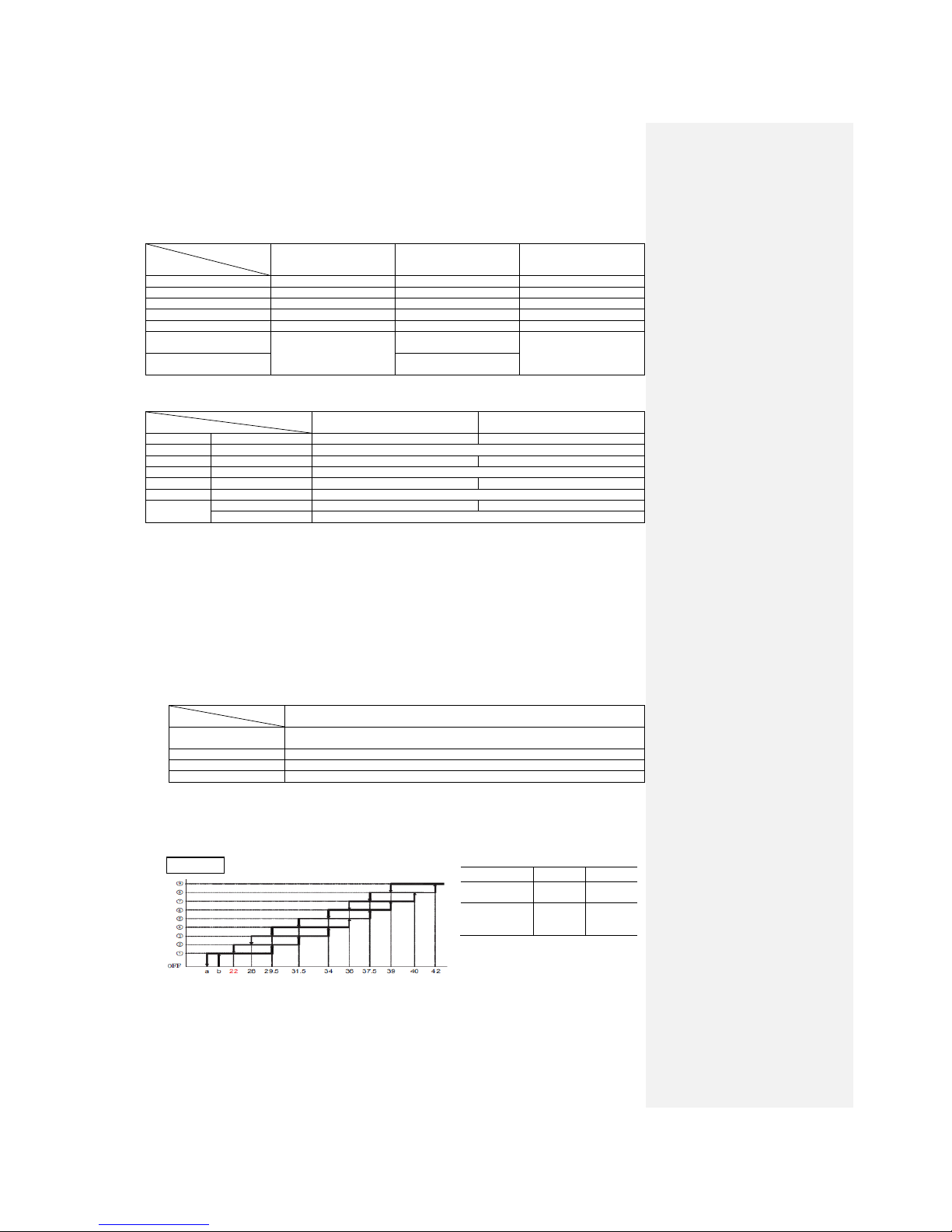
4.4 Flap control
(1) Swing of vertical flap (SM1)
The vertical flap continuously swings upward and downward.
Set the angle and pulse count (0° for horizontal)
① ② ③ ④ ⑤ ⑥ ⑦
⑧
SM1
Angle
75°
70°
65°
60°
55°
50°
45°
40°
Pulse count
0
57
114
171
228
284
341
398
⑨
⑩
SM1
Angle
32°
30°
25°
20°
15°
10°
5°
-24° Pulse count
489
512
569
626
683
739
796
1274
Note: Max control range: 1274 pulse.
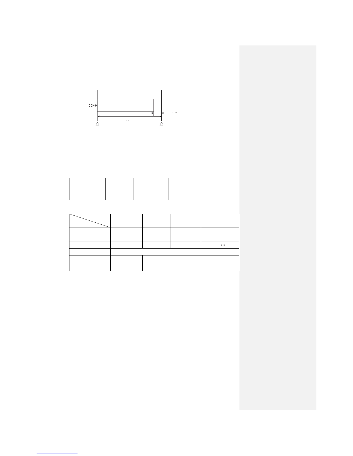
(2) Non-operating period
When the machine stops, the vertical flap fully closes.
-13-
(3) Flap memorizing function (where the vertical or horizontal flap stops)
When you press the AIR FLOW (Up/Down or Left/Right) button, the flap will operate at the
angle set. As this angle is memorized in the microcomputer, the flap will automatically operate
at the same angle next time the machine is started.
● Recommended angle of flap
(4) Flap control
The flap is controlled with the FLAP button on the remote controller.
(a) Automatic direction
The flap is automatically set to the best air flow angle in an operating mode.
1) Start time of operation
COOL and DRY operation HEAT operation
The flap moves repeatedly as The flap moves repeatedly as
shown in the above figure. shown in the above figure.
● In the HEAT mode, when the climator
(thermostat) functions or the DRY
operation is in progress, it becomes
horizontal automatically.
2) Non-operating period
When the machine stops, the flap fully closes.
(b) Flap memorizing function
As this angle is memorized in the microcomputer, the flap will automatically operate at the
angle next time the machine is started.
(c) Swing
As shown in the figure below, the flap swings upward/downward and to the left/right
continuously.
HEAT
(Slant forward
blowing)
COOL, DRY
(Horizontal
blowing)
Stops here for 1
minute
Swing
Swing
Stops here for 3
min. and 50 sec.
-14-
4.5 Comfort timer setting
If, in the COOL or HEAT mode or Automatic COOL or HEAT mode, the timer is set to ON, the
Comfort Timer functions.
The initial value is 15 minutes. The start time for next operation is determined according to the
relationship between the room temperature (sensor) at the time of setting and the set temperature
(max. 60 minutes).
Operating
mode
Correction value at the start of operation (minute)
COOL
3 < room temperature -
set temperature
1 < room temperature -
set temperature ≤ 3
room temperature - set
temperature ≤ 1
+5
No change
-5
HEAT
3 < room temperature -
set temperature
2 < room temperature -
set temperature ≤ 3
room temperature - set
temperature ≤ 2
+5
No change
-5
Notes: (1) The room temp. sensor (Th1) commences operation 5 minutes before the timer is ON,
regardless of the temperature.
(2) In the DRY or Automatic DRY mode, the function does not work.
However, in the Automatic DRY mode, the operation described in (1) commences.
(3) During the comfort reservation operation, the RUN lamp and TIMER lamp light up.
After expiration of the timer, the TIMER lamp goes off.
(Example) HEAT
Detect the temperature difference to compensate the start time of next operation.
15 min 10 min 5 min time set
earlier earlier earlier
● If the difference between the set temperature and room temperature is 4℃, according to the
above table, the correction value is +5 minutes, therefore, the start time of next operation is:
15 minutes earlier + 5 minutes = 20 minutes earlier
Compensation value
Start time of current operation
Set temp,
Room temp.
Time
-15-
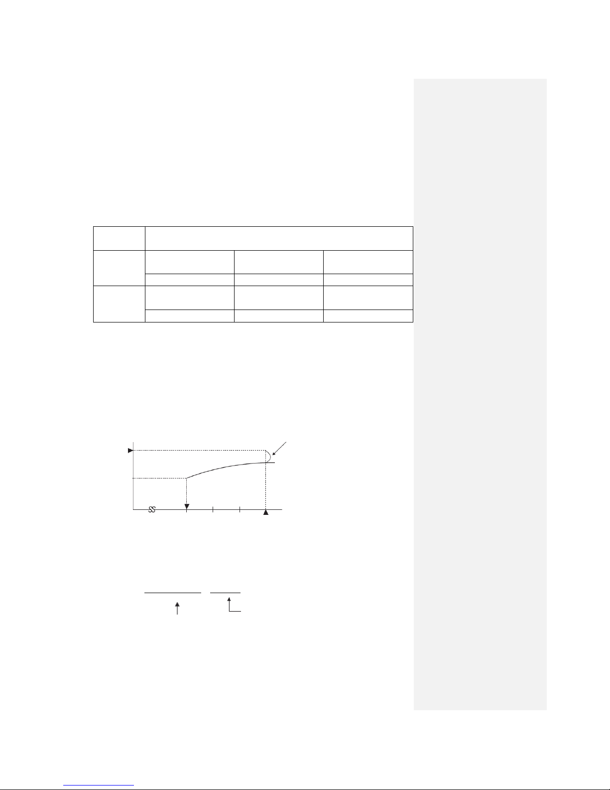
4.6 Outline of heating operation
(1) Operation of functional components
Item
Functional
component
Instruction frequency 0
Instruction frequency
other than 0
Changed to a value other
than 0 due to abnormal
stop
Indoor fan motor
ON
ON
OFF
Swinging flap
ON or OFF
ON or OFF
Stop position control
Indication
Light up
Light up
Light up or flash
52C relay
ON
ON
OFF in Stop mode
Outdoor fan motor
Depending on Stop mode
ON
Depending on Stop mode
4-way valve
Depending on Stop mode
ON (Indoor continuous
instructions-1)
Depending on Stop mode
EEV
Depending on EEV
control
(2) Air flow switching
(a) The inverter instruction frequency changes within the range of selected air flow.
Model
Air flow switching
SRK25QA-S
SRK35QA-S
AUTO
Frequency
30-110 rps
30-112 rps
Air flow
Corresponding to frequency
HI
Frequency
30-110 rps
30-112 rps
Air flow
8th speed
ME
Frequency
30-72 rps
30-78 rps
Air flow
5th speed
LO
Frequency
30-42 rps
30-50 rps
Air flow
3rd speed
(b) When the defrosting or protection device is actuated, operation is performed in the
corresponding mode.
(c) Outdoor fan operates in accordance with the instruction frequency.
(3) Details of control in each operating mode
(a) Fuzzy operation
Deviation between the room temperature setting compensation value and the suction air
temperature is calculated in accordance with the fuzzy rule, and used for control of the air
flow and the inverter frequency.
(b) Heating constant temperature operation (HEAT operation)
● Operating conditions
If the frequency obtained with the fuzzy calculation drops below -24 rps during the heating
fuzzy operation, the operation changes to the heating constant temperature operation.
● Detail of operation
Model
Item
SRK25QA-S, SRK35QA-S
Inverter instruction
frequency
0 rps [Comp. stopped]
Indoor fan
Heat-retaining (normal operating mode)→1st speed (OFF)
Outdoor fan
According to the stop mode
Flap
According to the HEAT and DRY flap control
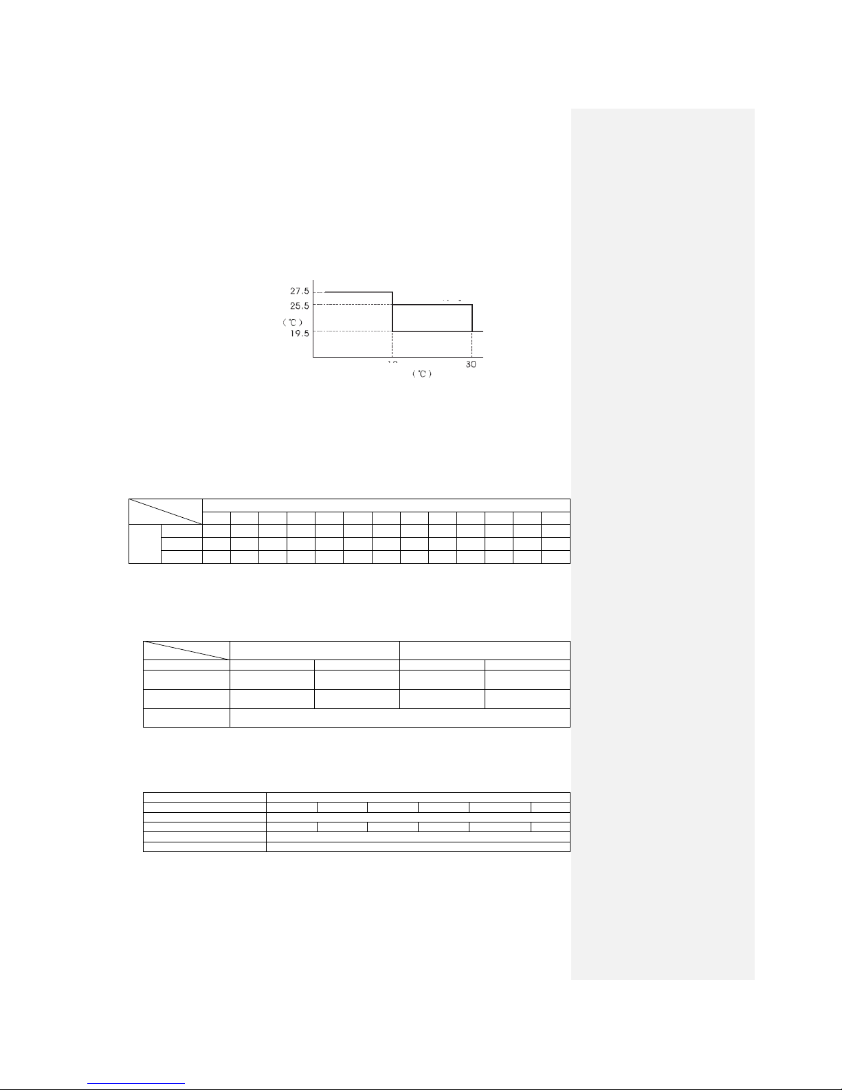
(c) Heat-retaining operation
During the heating operation, the indoor fan is controlled based on the temperature of the
outdoor heat exchanger (measured by indoor heat exchanger sensor) to prevent cool wind
from blowing.
● Normal operation (Usual heating operation, HI POWER operation)
Temp. of indoor heat exchanger (°C)
Note: (1) For the values of A and B, see the above table.
● Values of A, B
A B
At 0 rps
instruction
22
25
Other than 0
rps
instruction
10
15
Indoor fan
Fan speed
-16-
● Heat-retaining M mode (automatic, economical operation (15 minutes))
Temp. of indoor heat exchanger (°C)
Note: (1) For the values of A and B, see the above table.
● Values of A, B
A B
At 0 rps
instruction
22
25
Other than 0
rps
instruction
10
15
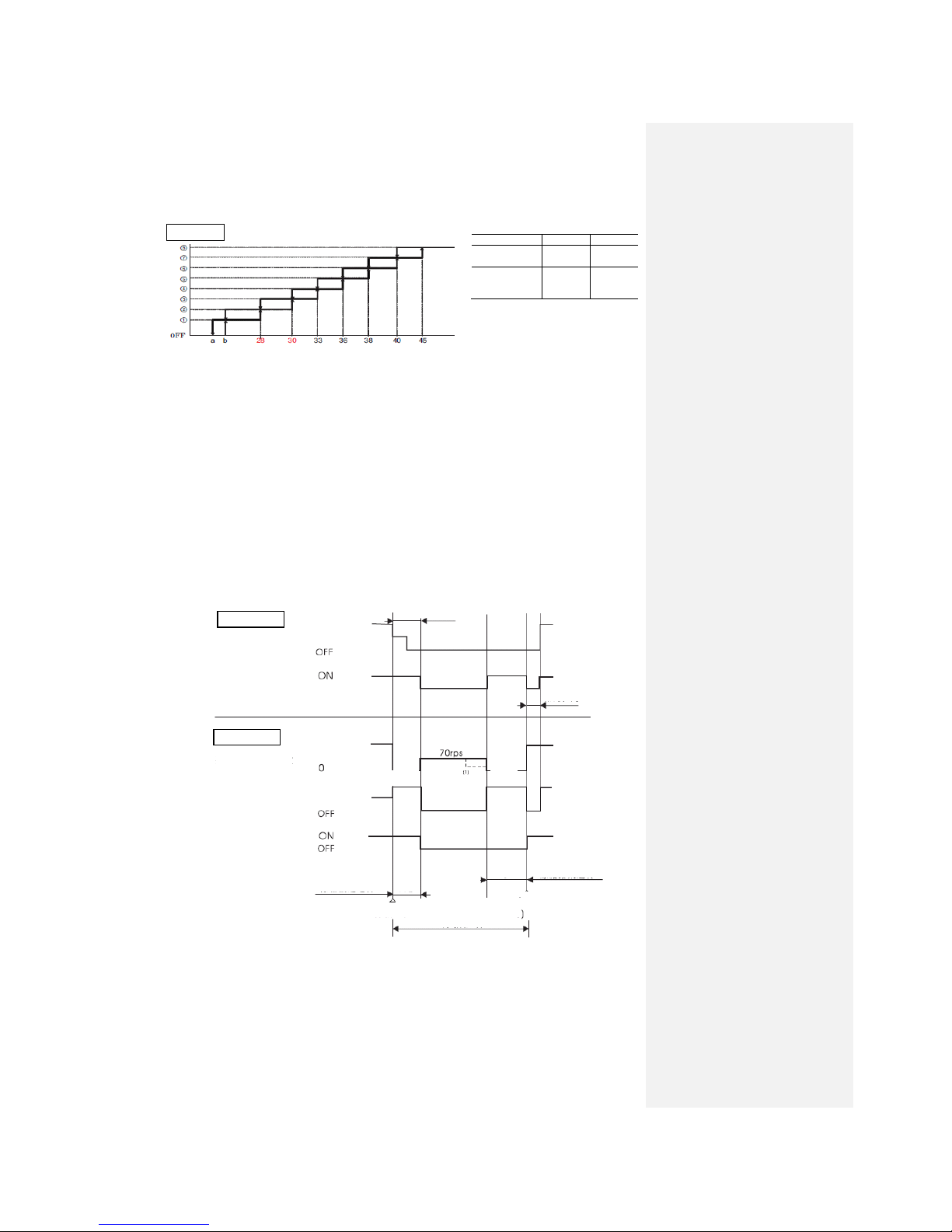
(d) Defrosting operation
1) Starting conditions (The defrosting operation is started only when all of the
following conditions are met.)
① 35 minutes after start of heating operation (accumulated operation time).
② 35 minutes after end of defrosting operation (accumulated compressor operation
time).
③ The temperature measured by the outdoor heat exchanger liquid pipe sensor (Th4) has
been below –5ºC for 3minutes continuously.
④ Temperature measured by outdoor air temp. sensor (Th5) - Temperature measured by
outdoor heat exchanger liquid pipe sensor (Th4) > 5ºC.
⑤ During compressor operation. (However, the defrosting can’t operate within 10
minutes after the compressor commences operation.)
In addition, if the count exceeds 10 times when the inverter frequency of the indoor
controller is 0 rps during heating operation, only ①, ② and ③ should be satisfied.
(However, the temperature measured by Th4 is below -5°C when the frequency is
above 62 rps and below -4°C when the frequency is below 62 rps.)
2) Operation of functional components during defrosting operation
● 25, 35 models
Note: When the temperature measured by the outdoor heat exchanger sensor (Th4) becomes 2 ºC or higher,
the inverter instruction frequency changes from 70 rps to 50 rps.
3) Ending conditions (Operation returns to the heating operation when either of the
following is met.)
① Temperature measured by outdoor heat exchanger sensor (Th4): 13ºC or higher
② Continued operation time of defrosting: More than 10 min.
Indoor fan
Fan speed
Indoor
Corresponding
speed
Heat-retaining
Indoor fan
RUN lamp
Flashing
(Heat-retaining)
Heat-retaining
Outdoor
Fuzzy calculated
value
Inverter
instruction
frequency
Outdoor fan
4-way valve
Corresponding
speed
Defrosting operation
preparation
Defrosting operation
50 sec.
60 sec.
6th
speed
6th
speed
Final defrosting operation
Normal heating operation
Defrosting control
Defrosting end
(Th4≥13C, 10 min
-17-
(e) HI POWER Heating operation (HI POWER button on remote controller: ON)
High rotate speed operation for15 minutes.
● Detail of operation
Model
Item
SRK25QA-S
SRK35QA-S
Inverter instruction frequency
110
112
Indoor fan
Heat-retaining mode (max. 9th speed)
Outdoor fan
Corresponding to instruction frequency
Notes: (1) Room temperature can’t be adjusted during the HI POWER operation.
(2) Priority is given to actuation of protective device even during the HI POWER operation.
4.7 Outline of cooling operation
(1) Operation of functional components
Item
Functional component
Instruction frequency 0
Instruction frequency
other than 0
Becomes 0 due to
abnormal stop
Indoor fan motor
ON
ON
OFF
Swinging flap
ON or OFF
ON or OFF
Stop position control
Indication
Light up
Light up
Light up or flash
52C relay
ON
ON
OFF in Stop mode
Outdoor fan motor
Depending on Stop mode
ON
Depending on Stop mode
4-way valve
Depending on Stop mode
OFF (Indoor continuous
instructions-0)
Depending on Stop mode
EEV
Depending on EEV
control
(2) Air flow switching
(a) The inverter instruction frequency changes within the range of selected air flow.
Model
Air flow switching
SRK25QA-S
SRK35QA-S
AUTO
Frequency
20~92 rps
20~106 rps
Air flow
Corresponding to frequency
HI
Frequency
20~92 rps
20~106 rps
Air flow
6th speed
ME
Frequency
20~55 rps
20~66 rps
Air flow
4th speed
LO
Frequency
20~34 rps
20~38 rps
Air flow
2nd speed
(b) When the protection device is actuated, operation is performed in the corresponding mode.
(c) Outdoor fan operates in accordance with the instruction frequency.
(3) Details of control in each operating mode
(a) Fuzzy operation
Deviation between the room temperature setting compensation value and the suction air
temperature is calculated in accordance with the fuzzy rule, and used for control of the air
flow and the inverter frequency.
(b) Cooling constant temperature operation
● Operating conditions
If the frequency obtained with the fuzzy calculation drops below -24 rps during the
cooling fuzzy operation, the operation changes to the cooling constant temperature
operation.
● Detail of operation
Model
Item
SRK25QA-S, SRK35QA-S
Inverter instruction
frequency
0 rps [Comp. stopped]
Indoor fan
According to the Indoor Fan Operating Mode Table (corresponding to fan speed)
Outdoor fan
Stop
-18-
(c) HI POWER Cooling operation (HI POWER button on remote controller: ON)
Unrelated to set temperature. Continuous operation for15 minutes.
● Detail of operation
Model
Item
SRK25QA-S
SRK35QA-S
Inverter instruction frequency
92
106
Indoor fan
7th speed
Outdoor fan
Corresponding to instruction frequency
Notes: (1) Room temperature can’t be adjusted during the HI POWER operation.
(2) Priority is given to actuation of protective device even during the HI POWER operation.
4.8 Outline of drying operation
(1) After the fan commences operation (1st speed for indoor fan, 3rd speed for outdoor fan) within
20 seconds after the start of operation, the room temperature TION, the outdoor air temp. sensor
TO and set temperature SP are checked to determine whether to use cooling & drying or heating
& drying.
● TION > SP-3 or TO ≥ 19℃: cooling & drying
● TION ≤ SP-3 or TO < 19℃: heating & drying
Cooling & drying or heating & drying is selected again one hour after selection.
(2) Outline of control
(a) Cooling & drying
● Room temperature TION, set temperature SP and value of humidity sensor are checked
every 5 minutes after the cooling & drying is selected to determine the operation range of
drying.
● Operation ranges are shown in the table below:
Humidity
range
TION<SP-1
SP-1≤TION<SP
SP≤TION<SP+2
SP+2≤TION
Normal
operation
Low humidity
Range I
Range C
Range B
Range A
High
humidity
Range I
Range F
Range E
Range D
Economical
type
Range I
Range C
Range C
Range E
● The range of humidity sensor is judged according to the following:
● The operations of the components in the operation range of cooling & drying are as
follows:
Operation range
Functional component
A B C D E F I
Instruction frequency
HZ
34
26
20
40
26
20 0 Rotate speed of indoor
fan
4th
speed
2nd
speed
2nd
speed
4th
speed
2nd
speed
2nd
speed
1st speed OFF
Rotate speed of
outdoor fan
Corresponding to instruction frequency
OFF
4-way valve
OFF (indoor continuous instructions - 0)
OFF F (indoor
continuous
instructions - 0)
● When the set temperature change signal is received, the original range will be continued till
finished; in the next 5 minutes, the room temperature TION, set temperature SP and value
of humidity sensor are checked to determine the new operation range.
● When a range other than Range I is switched to Range I, the control is as follows:
(A) According to the Stop mode (B);
High humidity range
Low humidity range

-19-
(B) Prevent Range I in jiggle operation from changing to Range C operation.
-20-
● Operation of Range I:
(b) Heating & drying
After heating & drying is determined, heating operation begins 3 minutes (3 min. timer)
after the stop of the compressor. When the room temperature TION is higher than the set
temperature SP by more than 2℃, the room temperature TION and set temperature SP are
checked every 5 minutes to determine the operation range of heating & drying.
● Operation ranges are shown in the table below:
TION<SP-1
SP-1≤TION<SP
SP≤TION
Usual operation
Range O
Range L
Range M
Economical type
Range O
Range L
Range M
● The operations of the components in the operation range of cooling & drying are as
follows:
Operation range
Functional component
Heating
operation
M L O
Instruction frequency
HZ
40
26
20
0
Indoor fan
5th speed
2nd speed
2nd speed
1st speed OFF
Outdoor fan
Corresponding to instruction frequency
OFF
4-way valve
OFF (indoor
continuous
instructions - 1)
OFF F (indoor continuous instructions - 0)
● During the heating operation, the protection functions of defrosting operation and high
pressure control are effective. (This is also the case for usual heating operation.)
● If, during the operation of this control range, the set temperature TP change signal is received
and the heating operation of heating & drying is changed immediately, TION judgment will
be conducted. For other operations, it operates in the range before temperature confirmation
every 5 minutes and in the new range after judgment.
● When a range other than Range O is switched to Range O, the control is as follows:
(A) According to the Stop mode;
(B) Prevent Range O in jiggle operation from changing to Range L operation.
●Range O operation is the same as Range I operation of cooling & drying.
● No heat-retaining is conducted during heating operation.
1st speed
Indoor fan
25 sec.
Temperature and humidity check
5 min.
Temperature and humidity check
-21-
4.9 Outline of automatic operation
(1) Determination of operating mode
After the indoor and outdoor fans operate at the 2nd sped and 3rd speed respectively for 20
seconds, the system checks the room temperature and outdoor air temperature to determine the
operating mode and the room temperature setting compensation value, and then enters the
automatic operation.
(2) The unit checks the temperature every hour after the start of operation and, if the result of
check is not the same as the previous operating mode, it will change the operating mode.
(3) When the unit is started again within one hour after the stop of automatic operation or when
the automatic operation is selected during heating, cooling or drying operation, the unit will
operate in the original operating mode.
(4) Set temperature can be adjusted within the following range. There is the relationship as shown
below between the signals of the wireless remote controller and the set temperature.
Signals of wireless remote controller (indication)
-6
-5
-4
-3
-2
-1 0 +1
+2
+3
+4
+5
+6
Set
temp.
Cooling
18
19
20
21
22
23
24
25
26
27
28
29
30
Drying
18
19
20
21
22
23
24
25
26
27
28
29
30
Heating
20
21
22
23
24
25
26
27
28
29
30
31
32
4.10 Economical operation (ECONO button on remote controller: ON)
(1) When the ECONO button is pressed, the power is controlled for gentle operation in the status
which is not too cold or too hot. In this case, the temperature in the Cooling mode is higher
than the set temperature by 1.5ºC (increasing 0.5ºC per hour), and the temperature in the
Heating mode is lower than the set temperature by 2.5ºC (decreasing 0.5ºC per hour).
Model
Item
SRK25QA-S
SRK35QA-S
Operating mode
Cooling
Heating
Cooling
Heating
Inverter instruction
frequency
20~46 rps
20~60 rps
20~62 rps
20~76 rps
Rotate speed of
indoor fan
2nd, 4th speed
3rd, 5th speed
2nd, 4th speed
3rd, 5th speed
Rotate speed of
outdoor fan
3rd speed
4.11 Air blowing operation
(1) When the fresh air signal from the remote controller is received, the fresh air operation begins.
(2) The so-called “fresh air operation” refers to the air blowing operation in the whole machine
with filter.
Air flow switching
Automatic
Hi
Me
Lo
Economical
Instruction frequency HZ
0
Rotate speed of indoor fan
6th speed
5th speed
4th speed
3rd speed
2nd speed
Rotate speed of outdoor fan
-
4-way valve
Same as cooling
(3) In this control, the continuous transmission error protection function can be neglected.
(4) In the fresh air operation, all timing functions are effective.
Cooling
Drying
Heating
Room temperature
Outdoor temperature
-22-
4.12 CLEAN operation control
About CLEAN operation:
In the cooling and drying mode, when the unit is turned off, the fan of the indoor unit will
continue to run for 120 minutes to discharge the water from the unit for the purpose of
mould-proof.
CLEAN setting
Example: Setting of CLEAN operation when the unit is turned off after cooling operation.
1: When the air conditioner is in the stop mode, press the ON/OFF button.
2: Press the MODE button to set the cooling mode.
3: Press the CLEAN button and CLEAN indication on the display will light up.
Cancelation of CLEAN operation
Press the CLEAN button and CLEAN indication on the display will disappear.
.
4.13 Electronic expansion valve (EEV) control function
(1) General control range: 0~470 pulse.
(2) The open loop control and area control are combined for EEV control.
-23-
5 Installation
○ Use this system only for household and
residence.
○ This appliance must be installed according to the national wiring regulation.
○ A 2-level switch must be used for the fixed wiring of the power supply and its disconnection
clearance must be at least 3mm.
○ If the outdoor unit may tip over or move and drop from the original installation location, use
trip bolts or string to secure it in place.
○ The liquid pipe and gas pipe in the piping should be insulated with thermal insulation.
SAFETY PRECAUTIONS
• Please read this “SAFETY PRECAUTIONS” carefully before the installation work in order to ensure correct installation.
• T he precautions described below are divided into WARNING and CAUTION. The matters with possibilities leading to
serious consequences such as death or serious personal injury due to erroneous handling are listed in the WARNING, however
the matters listed in CAUTION may sometimes lead to serious accidents. These are very important precautions for safety. Be
sure to observe all of them without fail.
• For qualified installing personnel, take precautions in respect to themselves by using suitable protective clothing, groves, etc., and then
perform the installation works.
• Please pay attention not to fall down the tools, etc. when installing the unit at the high position.
• If unusual noise can be heard during operation, consult the local dealer.
• Be sure to confirm no anomaly on the equipment by commissioning after completed installation and explain the operating methods as
well as the maintenance methods of this equipment to the user according to the owner’s manual.
• Symbols which appear frequently in the text have the following meaning:
Strictly prohibited
Observe instructions
Provide proper earthing
• Keep the installation manual together with owner’s manual at a place where any user can read. Moreover if necessary, ask to hand
them to a new user.
WARNING
• Installation must be carried out by the qualified
installer and only the specified optional components
should be used.
If you install the system by yourself, it may cause serious
trouble such as water leaks, electric shocks, fire and
personal injury, as a result of a system malfunction.
• Install the system in full accordance with the
instruction manual.
Incorrect installation may cause bursts, personal injury,
water leaks, electric shocks and fire.
• Be sure to use only for household and residence.
If this appliance is installed in inferior environment such
as machine shop etc., it can cause malfunction.
• Use the original accessories and the specified
components for installation.
If parts other than those prescribed by us are used, it may
cause drop of machine, water leaks, electric shocks, fire,
refrigerant leakage, insufficient performance, poor control,
and personal injury.
• Install the unit in a location with good support and
ensure the unit is stable when installed, so that it can
withstand earthquakes and strong winds.
Unsuitable installation locations can cause the unit to fall
and cause material damage and personal injury.
• Ventilate the working area well in the event of
refrigerant leakage during installation.
If the refrigerant comes into contact with naked flames,
poisonous gas is produced.
• When the equipment is to be installed in a small room,
take preventive measures to avoid refrigerant leakage
exceeding the density limit.
Consult with the installation professionals about the
preventive measures. If the density is greater than the limit
of refrigerant, it may cause serious accidents such as
refrigerant leakage, shortage of oxygen, etc.
• Confirm there is no refrigerant leakage after the
installation.
If the refrigerant leaked comes into contact with the fire of
an air blowing type heater, oven, etc., poisonous gas is
produced.
• Use the prescribed pipes, flare nuts and tools for
R410A.
Using conventional parts (for R22) can cause the unit
failure and serious accidents due to burst of the refrigerant
circuit.
• Tighten the flare nut by torque wrench with specified
method.
If the flare nut were tightened with excess torque, this may
cause burst and refrigerant leakage after a long period.
• Do not open the operation valves for liquid line and gas
line until completed refrigerant piping work, air
tightness test and evacuation.
If the compressor is operated when operation valves are
open before the connection of refrigerant piping work is
completed, it can cause frostbite or injury due to rapid
refrigerant leakage, and burst or personal injury due to
anomalously high pressure in the refrigerant circuit into
which air is sucked.
• The electrical installation must be carried out by the
qualified electrician in accordance with “the norm for
electrical work” and “national wiring regulation”, and
the system must be connected to the dedicated circuit.
Power supply with insufficient capacity and incorrect
function done by improper work can cause electric shocks
and fire.
• Be sure to shut off the power before starting electrical
work.
Failure to shut off the power can cause electric shocks,
unit failure or incorrect function of equipment.
• Be sure to use the cables conformed to safety standard
and cable ampacity for power distribution work.
Unconformable cables can cause electric leak, anomalous
heat production or fire.
• This appliance must be connected to main power
supply by means of a circuit breaker or switch
(fuse:16A) with a contact separation of at least 3mm.
• If the appliance has a plug, the plug must comply with
IEC 60884-1.
• Use the prescribed cables for electrical connection,
tighten the cables securely in terminal block and
relieve the cables correctly to prevent overloading the
terminal block.
Loose connections or cable mountings can cause
anomalous heat production or fire.
• Arrange the wiring in the control box so that it cannot
be pushed up further into the box. Install the case and
service panel correctly.
Incorrect installation may result in overheating and fire.
• Be sure to mount the service panel.
Incorrect mounting can cause electric shocks or fire due to
intrusion of dust or water.
• Be sure to switch off the power supply before
installation, inspection or servicing.
If the power supply is not shut off, there is a risk of
electric shocks, unit failure or personal injury due to the
unexpected start of fan.
Precautions for installation
-24-
WARNING
• To recover refrigerant, stop the compressor before closing the valve and disconnecting the refrigerant piping.
If the refrigerant piping is disconnected before the compressor stops and when the service valve is opened, it can cause
frostbite or injury due to rapid refrigerant leakage, and burst or personal injury due to anomalously high pressure in the
refrigerant circuit into which air is sucked
• Do not put the drainage pipe directly into drainage
channels where poisonous gases such as sulphide gas
can occur.
Poisonous gases will flow into the room through drainage
pipe and seriously affect the user’s health and safety.
• Never connect the power cord to the central socket.
Never use extended wires or share a socket with other
electrical appliances.
This may cause fire or electric shocks due to defective
contact, poor insulation and over-current etc.
• Do not discharge R410A to the atmosphere. R410A is a
fluoride greenhouse gas and can cause global warming
if it is discharged to the atmosphere.
• Ensure that no air enters in the refrigerant circuit
when the unit is installed and removed.
If air enters in the refrigerant circuit, the pressure in the
refrigerant circuit becomes too high, which can cause
burst and personal injury.
• Do not bundle or wind the power cord. Or, do not
deform the power plug by treading it.
This may cause electric shocks, heating or fire.
• Do not run the unit with removed panels or
protections.
Touching rotating equipments, hot surfaces or high
voltage parts can cause personal injury due to entrapment,
burn or electric shocks.
• Do not perform any change of protective device itself
or its setup condition.
The forced operation by short-circuiting protective device
of pressure switch and temperature controller or the use of
non specified component can cause fire or burst.
• Carry out the electrical work for ground lead with care.
Do not connect the ground lead to the gas line, liquid line, lightning conductor or telephone line’s ground lead. Incorrect
grounding can cause unit faults such as electric shocks due to short-circuiting. Never connect the ground lead to the gas
line as gas leakage can cause explosion or fire.
CAUTION
• Use the circuit breaker with correct breaking capacity
at all electrodes.
If a wrong breaker is used, it can cause the unit
malfunction and fire.
• Earth leakage breaker must be installed.
If the earth leakage breaker is not installed, it can cause
fire or electric shocks.
• Secure a space for installation, inspection and
maintenance specified in the manual.
Insufficient space can result in accident such as personal
injury due to falling from the installation place.
• After maintenance, all wi ring, wiring ties and the like,
should be returned to their original state and wiring
route, and the necessary clearance from all metal parts
should be secured.
• Take care when carrying the unit by hand.
If the unit weighs more than 20kg, it must be carried by
two or more persons. Do not carry by the plastic straps,
always use the carry handle when carrying the unit by
hand. Use gloves to minimize the risk of cuts by the
aluminum fins.
• Dispose of any packing materials correctly.
Any remaining packing materials can cause personal
injury as it contains nails and wood. And to avoid danger
of suffocation, be sure to keep the plastic wrapper away
from children and to dispose after tearing it up.
• Be sure to insulate the refrigerant pipes so as not to
condense the ambient air moisture on them.
Insufficient insulation can cause condensation, which can
lead to moisture damage on the ceiling, floor, furniture
and any other valuables.
• When the air conditioner is operating (cooling &
drying operation) and the ventilator installed in the
room is also running, there is the possibility that drain
water may backflow as the room enters the negative
pressure state. Therefore, set up the opening port to let
air enter the room to provide appropriate ventilation
(for example, open the door a little). In addition, just
as above, set up the opening port if the room enters the
negative pressure state due to the aerator for the high
rise apartment etc.
• Install isolator or disconnect switch on the power
supply wiring in accordance with the local codes and
regulations.
• Do not install the unit in the locations listed below.
• Locations where carbon fiber, metal powder or any
powder is floating.
• Locations where any substances that can affect the unit
such as sulphide gas, chloride gas, acid and alkaline can
occur.
• Vehicles and ships.
• Locations where cosmetic or special sprays are often
used.
• Locations with direct exposure to oil mist and steam
such as kitchen and machine plant.
• Locations where an y machines which generate high
frequency harmonics.
• Locations with salty atmospheres such as coastlines.
• Locations with heavy snow.
• Locations where the unit is exposed to chimney smoke.
• Locations at high altitude (more than 1000m high).
• Locations with ammonic atmospheres.
• Locations where heat radiation from other heat source
can affect the unit.
• Locations without good air circulation.
• Locations with any obstacles which can prevent inlet
and outlet air of the unit.
• Locations where short circuit of air can occur (in case of
multiple units installation).
• Locations where strong air blows against the vent of
outdoor unit. It can cause remarkable decrease in
performance, corrosion and damage of components,
malfunction and fire.
-25-
CAUTION
• Do not install the outdoor unit in the locations listed
below.
• Locations where discharged hot air or operating sound of
the outdoor unit can bother neighborhood.
• Locations where outlet air of the outdoor unit blows
directly to animals or plants. The outlet air may cause
adverse impact on plants, etc.
• Locations where vibration and operation sound
generated by the outdoor unit can affect seriously (on the
wall or at the place near bed room).
• Locations where vibration can be amplified and
transmitted due to insufficient strength of structure.
• Locations where an equipment affected by high
harmonics is placed (TV set or radio receiver is placed
within 5m).
• Locations where drainage cannot run off safely. It can
affect surrounding environment and cause a complaint.
• Do not install the unit where corrosive gas (such as
sulfurous acid gas etc.) or combustible gas (such as
thinner and petroleum gases) can accumulate or
collect, or where volatile combustible substances are
handled.
Corrosive gas can cause corrosion of heat exchanger,
breakage of plastic parts and etc. And combustible gas can
cause fire.
• Do not use the base flame for outdoor unit which is
corroded or damaged due to long periods of operation.
Using an old and damaged base flame can cause the unit
falling down and cause personal injury.
• Do not touch the suction or a luminum fin on the
outdoor unit.
This may cause injury.
• Do not install the outdoor unit in a location where
insects and small animals can inhabit.
Insects and small animals can enter the electric parts and
cause damage or fire. Instruct the user to keep the
surroundings clean.
• Do not i nstall nor use the system close to the
equipment that generates electromagnetic fields or
high frequency harmonics.
Equipment such as inverters, standby generators, medical
high frequency equipments and telecommunication
equipments can affect the system, and cause malfunctions
and breakdowns. The system can also affect medical
equipment and telecommunication equipment, and
obstruct its function or cause jamming.
• Do not use any materials other than a fuse with the
correct rating in the location where fuses are to be
used.
Connecting the circuit with copper wire or other metal
thread can cause unit failure and fire.
• Do not touch any buttons with wet hands.
It can cause electric shocks.
• Do not touch any refrigerant pipes with your hands
when the system is in operation.
During operation the refrigerant pipes become extremely
hot or extremely cold depending on the operating
condition, and it can cause burn injury or frost injury.
• Do not put anything on the outdoor unit and operating
unit.
This may cause damage of the object or injury due to the
fall of the object.
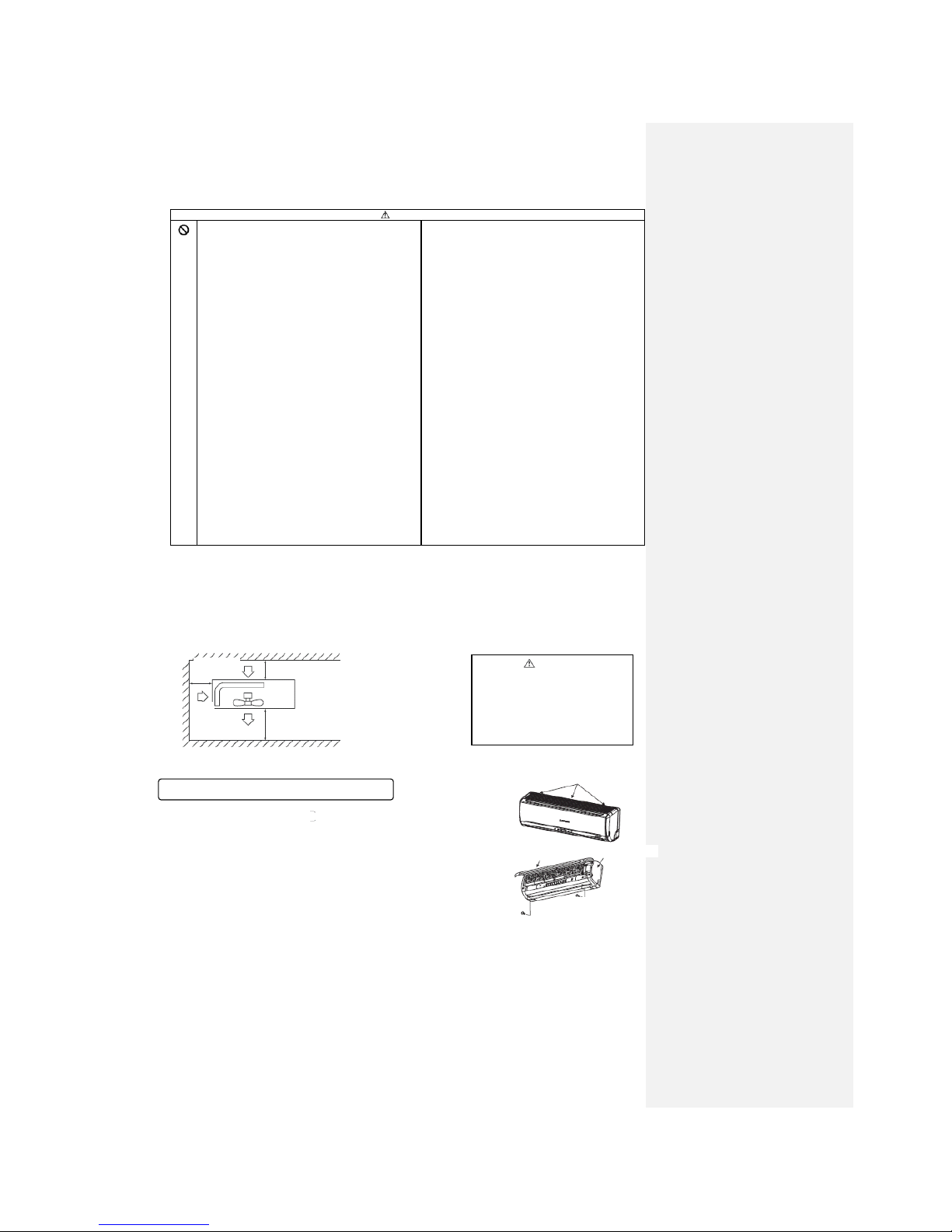
5.1 Selection of installation location
○ The appliance must be installed at a location with the air intake and vents being 10cm away
from walls.
(In case the fence is 1.2m or above in height, or is overhead, the sufficient space between the
unit and walls shall be secured.)
○ When the unit is installed, the space of the following dimension shall be secured.
Air intake
10cm MIN
No obstacles (Service
space for electrical
parts))
Air
intake
Air outlet
60cm MIN
Caution
If the wall is 1.2m or above in
height or there is a ceiling, the
sizes should be greater than
those indicated above.
10cm MIN
How to remove and install the front panel
○ Removal
① Remove the air inlet
grille.
② Remove the 2 screws
securing the front panel.
③ Remove the 3 latches
on the upper part of the
front panel and remove the
front panel from the unit.
○ Installation
① Remove the air filter.
② Cover the unit with the
front panel.
③ Tighten the 2 screws to
secure the front panel.
④ Mount the air filter.
⑤ Mount the air inlet grille.
Latches
Front panel
Air inlet grille
Screw
Screw
-26-
Selection of installation location
Indoor unit
○ Where there are no obstructions and where
cool air and warm air can blow in the
room.
○ Where the indoor unit or wall does not
vibrate and where is strong.
○ Where there is adequate space for servicing.
(The space mentioned below is safe.)
○ Where wire and pipe mounting is
convenient.
○ Where direct sunlight and strong light do
not hit the unit.
○ Where water from the unit can drain easily.
○ Where there is at least 1 meter distance
from the TV set or radio. (Otherwise, it
may interfere with TV reception or produce
noise.)
Outdoor unit
○ Where rain, snow and sunlight do not
directly hit the unit, and where there is
enough air circulation.
○ Where blasts of cold or hot air and noise do
not bother the neighbors.
○ Where there are installation and servicing conditions.
○ A location where vibrations are not enhanced and where is strong.
※ Please avoid the following locations.
○ A location near the room, etc. to prevent the operating noise from causing trouble.
○ Where there are possibilities of flammable gas leaks.
○ Where there is constant exposure to harsh winds.
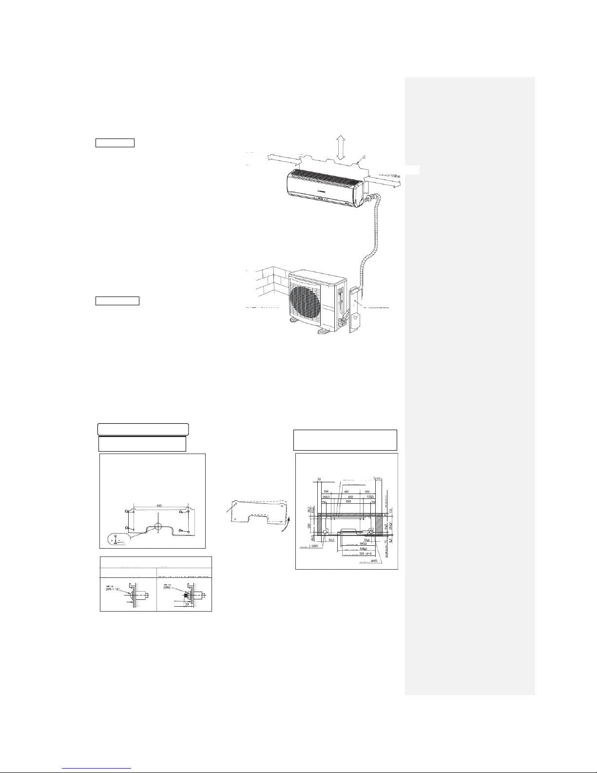
5.2 Installation of indoor unit
At least 6.5 cm from ceiling
Mounting plate
At least 10 cm from wall
At least 5 cm from wall
Electric component
service panel
Mountng of mounting plate
Fixing the mounting plate
Firstly find the position of
support or columella in the wall.
Check that the mounting location
is level and then fix the unit
more securely.
Plane mating mark
○ In the loose state, use
four screws to adjust
the mounting plate
horizontally.
Standard
hole
○ Turn the mounting
plate with the standard
hole as the center to
make it level.
Setting the relationship between
plate and indoor unit
Installation space
(Indoor unit) (Front view)
Service space
Indoor unit
Service
space
Mounting plate
Pipe
hole
Gas piping
Liquid piping
Drainage
Pipe hole
Service space
Service space
Fixing on the concrete wall
Using nut retainer
Using screw retainer
Mounting plate
Mounting
plate
Nut
Nut
Max.
-27-
Installation of indoor unit
Drilling holes and securing sleeve (optional)
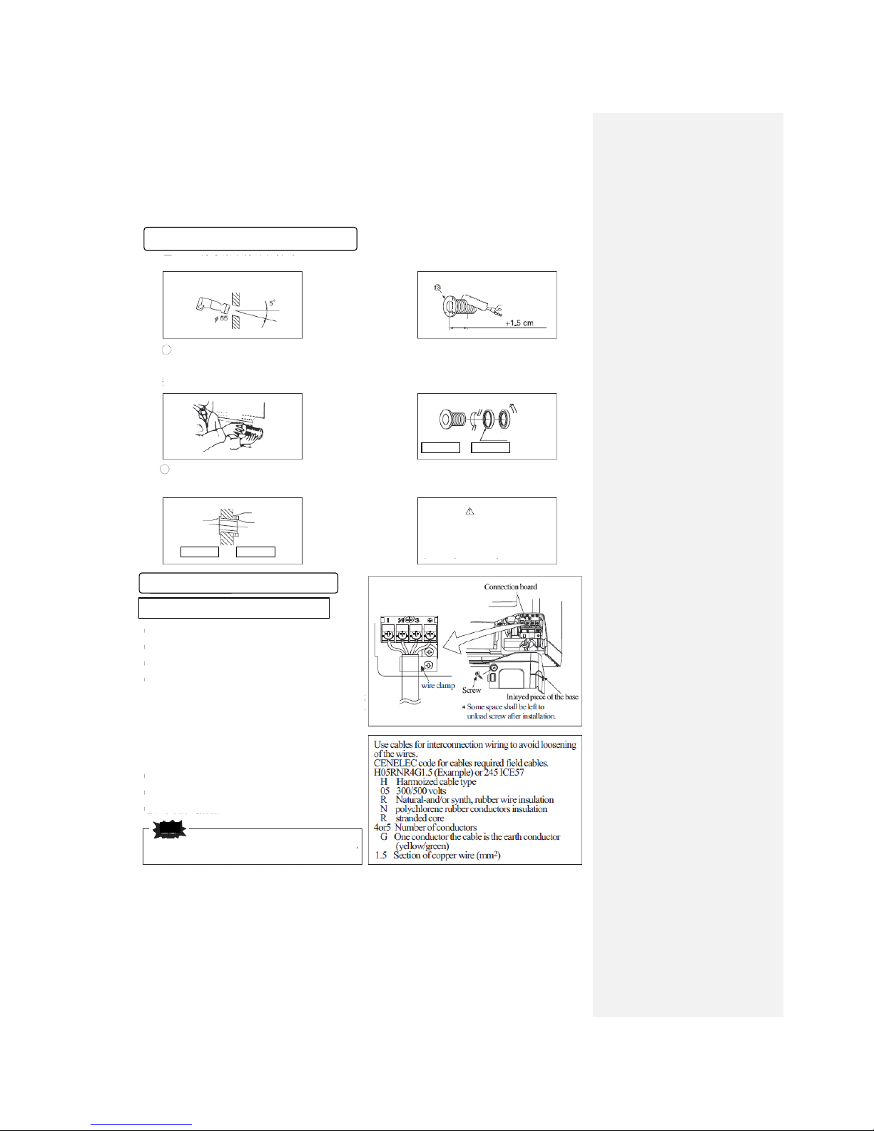
Drilling a hole with Φ65 whole core drill
Indoor
Outdoor
Adjusting the length of the sleeve
Top
Thickness of wall
Use the whole core drill to drill a hole.
Mounting the sleeve.
○ If the rear pipe is pulled out, cut the
lower part and right side of the axle
collar
Sleeve Declined plate Sealing ring
Turn to
tighten
Indoor
Outdoor
Putty
Insert the sleeve.
Sketch of state after mounting
Sleeve
Indoor
Outdoor
Declined
flange
Sealing ring
Caution
Drill a hole at an angle of 5°
Preparation for installation of indoor unit
Preparation for mounting of electric wire
① Open the air inlet grille.
② Remove the cover.
③Remove the wire clamp.
④ Connect the electric wire to the connection board
securely.
1) Connect the electric wire to the connection board
securely. If the electric wire is not fixed
completely, the contacting will be poor, thus
causes risk, as the connection board may heat
which causes fire.
2) Please note that the number of terminals of the
indoor and outdoor connections should not be
confused.
3) Use the wire clamp to connect the electric wire.
⑤ Connect the electric wire through the wire clamp.
⑥ Secure the cover.
⑦ Close the air inlet grille.
In case of failure of wiring connection, the indoor unit will stop running,
the RUN lamp will light up, and the TIMER lamp will flash.
Caution
 Loading...