

Mitsubishi Heavy Industries SRK28HD, SRK40HD Technical Manual

WALL MOUNTED TYPE
ROOM AIR-CONDITIONER
(Air to air heat pump type)
R22 use models
SRK28HD
SRK40HD
TECHNICAL MANUAL
& PARTS LIST
DRAFT
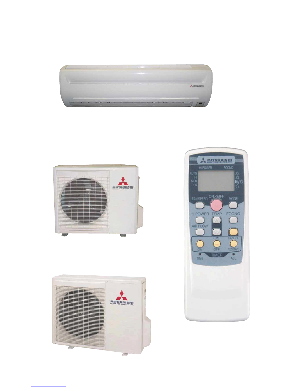
INDOOR UNIT
Models SRK28HD, SRK40HD
OUTDOOR UNIT
Model SRC28HD
REMOTE CONTROLLER
Model SRC40HD
-
1
-
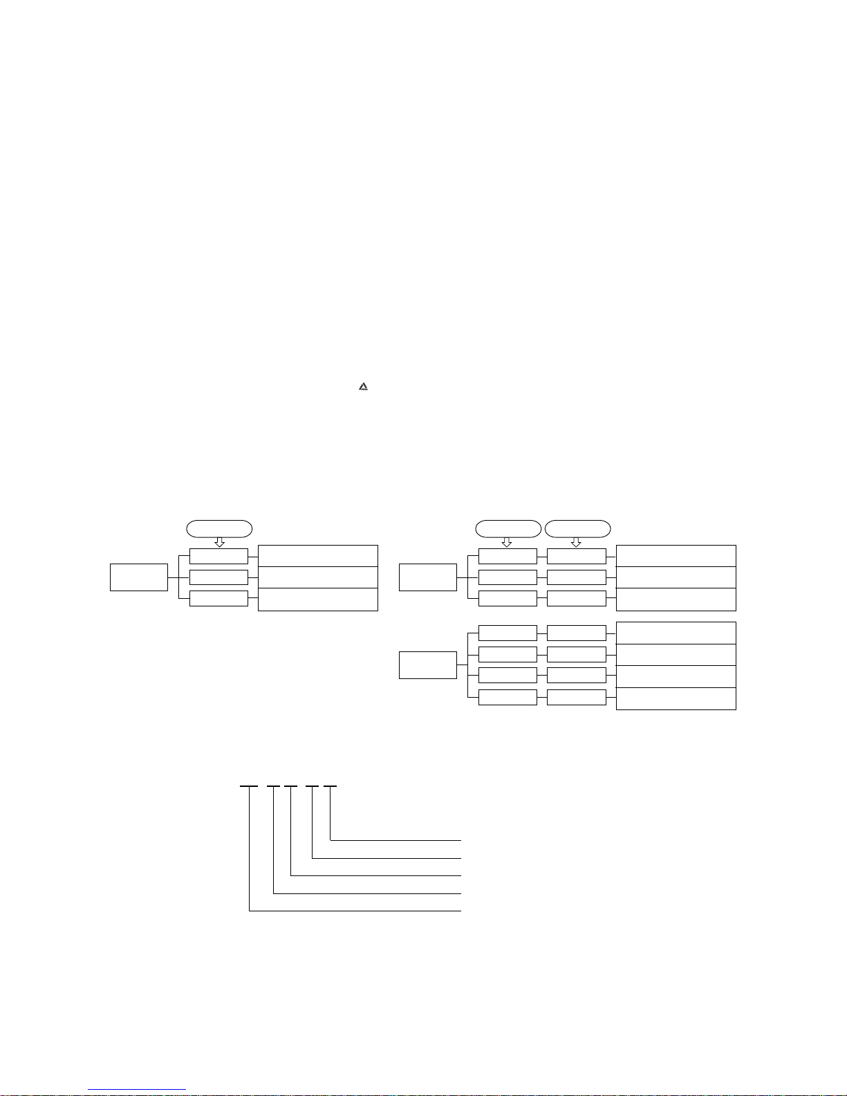
Serial signal transmission error
1 GENERAL INFORMATION
1.1 Specific features
The “Mitsubishi Daiya” room air-conditioner: SRK series are of split and wall mounted type and the unit consists of indoor unit and
outdoor unit with refrigerant precharged in factory. The indoor unit is composed of room air cooling or heating equipment with operation control switch and the outdoor unit is composed of condensing unit with compressor.
(1) Remote control flap
The flap can be automatically controlled by operating wireless remote controller.
¡ Air scroll: Flap operation is automatically control.
¡ Swing: This will swing the flap up and down.
¡ Memory flap: Once the flap position is set, the unit memorizes the position and continues to operate at the same position from
the next time.
(2) Automatic Operation
When the remote control switch is set on “auto( ) ”, it will either automatically decide operation mode such as cooling, heating
and thermal dry, or operate in the operation mode before it has been turned to automatic control.
(3) Self diagnosis function
¡ We are constantly trying to do better service to our customers by installing such judges that show abnormality of operation as
follows.
Series No.
Heat pump type
Product capacity
Wall mounted type
Split type room air-conditioner
1.2 How to read the model name
Example : SR K 40 H D
Room temperature thermistor error
Indoor fan motor error
Heat exchanger thermistor error
2 time flash
6 time flash
TIMER lamp
ON
1 time flash
Outdoor unit heat exchanger
thermistor error
Discharge pipe thermistor error
Outdoor temperature thermistor
error
2 time flash
4 time flash
RUN lamp
keeps flashing
1 time flash
OFF
OFF
OFF
Outdoor unit error
Compressor overheat
Current cut
2 time flash
5 time flash
RUN lamp
ON
1 time flash
2 time flash
5 time flash
1 time flash
6 time flash 6 time flash
RUN lamp TIMER lamp Outdoor (LED)
-
2
-
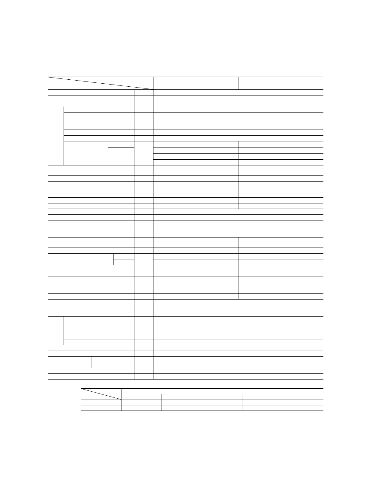
Item
Model
SRK28HD SRC28HD
Cooling capacity
(1)
W
Heating capacity
(1)
W
Power source 1 Phase, 220/230/240V, 50Hz
Cooling input kW
Running current (Cooling) A
Heating input kW
Running current (Heating) A
Inrush current A
COP
Cooling
sound level
Noise level
Power level
dB
(55) (60)
Heating
sound level
Power level (56) (60)
Exterior dimensions
Height × Width × Depth
mm
250 × 815 × 249 540 × 720 × 290
Color Cool white Stucco white
Net weight kg 9.0 32
Refrigerant equipment
Compressor type & Q’ty
– 2PS164D5BF02 (Rotary type) × 1
Motor kW – 0.75
Starting method – Line starting
Heat exchanger Louver fins & inner grooved tubing
Refrigerant control Capillary tubes
Refrigerant
(3)
kg R22 0.8 (Pre-Charged up to the piping length of 7.5m)
Refrigerant oil R 0.35 (SUNISO 4GDID or ATMOS M60)
Deice control MC control
Air handling equipment
Fan type & Q’ty
Tangential fan × 1 Propeller fan × 1
Motor W 14 15
(Cooling) 8.0 30
Air flow (at High)
(Heating)
CMM
8.5 30
Air filter, Q’ty Polypropylene net (washable) × 2–
Shock & vibration absorber – Cushion rubber (for compressor)
Electric heater ––
Operation control
Operation switch
Wireless-Remote controller –
Room temperature control MC. Thermostat –
Pilot lamp RUN (Green), TIMER (Yellow), HI POWER (Green), ECONO (Orange)
Safety equipment
O.D mm (in) Liquid line: φ6.35 (1/4″) Gas line: φ9.52 (3/8″)
Connecting method Flare connecting
Attached length of piping Liquid line: 0.4 m
Gas line : 0.33 m
–
Insulation Necessary (Both sides)
Drain hose Connectable
Power source cord 2.5 m (3 cores with Earth)
Size × Core number 1.5 mm2 × 4 cores (Including earth cable)
Connection wiring
Connecting method Terminal block (Screw fixing type)
Accessories (included) Mounting kit
Optional parts –
Notes (1) The data are measured at the following conditions.
2 SELECTION DATA
2.1 Specifications
Model SRK28HD (Indoor unit)
SRC28HD (Outdoor unit)
Item Indoor air temperature Outdoor air temperature
Standards
Operation DB WB DB WB
Cooling 27ºC 19ºC 35ºC 24ºC ISO-T1, JIS C9612
Heating 20ºC – 7ºC 6ºC ISO-T1, JIS C9612
(2) The operation data are applied to the 220/230/240V districts respectively.
(3) The refrigerant quantity to be charged includes the refrigerant in 7.5 m connecting piping.
If the piping length is longer, when it is less than 10 m, add 20 g refrigerant per meter and when it is 10 to 15 m, add 30 g refrigerant per meter.
Operation data
(1)
Refrigerant
piping
Frost protection, Serial signal error protection
Fan motor error protection
The piping length is 7.5m.
Compressor overheat protection, Overcurrent protection, Serial signal error protection
-
3
-
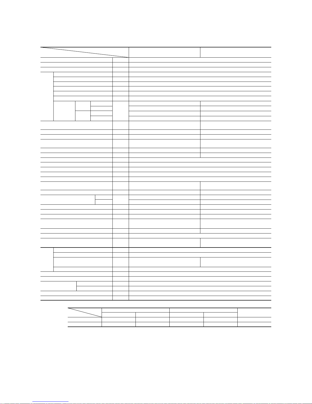
Item
Model
SRK40HD SRC40HD
Cooling capacity
(1)
W
Heating capacity
(1)
W
Power source 1 Phase, 220/230/240V, 50Hz
Cooling input kW
Running current (Cooling) A
Heating input kW
Running current (Heating) A
Inrush current A
COP
Cooling
sound level
Noise level
Power level
dB
(56) (63)
Heating
sound level
Power level (57) (64)
Exterior dimensions
Height × Width × Depth
mm
250 × 815 × 249 640 × 850 × 290
Color Cool white Stucco white
Net weight kg 9.0 41
Refrigerant equipment
Compressor type & Q’ty
– (RM5517GNE4)
Motor kW – 1.3
Starting method – Line starting
Heat exchanger Louver fins & inner grooved tubing
Refrigerant control Capillary tubes
Refrigerant
(3)
kg R22 (Pre-Charged up to the piping length of 7.5m)
Refrigerant oil R 0.6 (BARREL FREEZE 32SAM)
Deice control MC control
Air handling equipment
Fan type & Q’ty
Tangential fan × 1 Propeller fan × 1
Motor W 14 35
(Cooling) 9.0 38
Air flow (at High)
(Heating)
CMM
9.5 38
Air filter, Q’ty
Polypropylene net (washable) × 2
–
Shock & vibration absorber – Cushion rubber (for compressor)
Electric heater ––
Operation control
Operation switch
Wireless-Remote controller –
Room temperature control MC. Thermostat –
Pilot lamp RUN (Green), TIMER (Yellow), HI POWER (Green), ECONO (Orange)
Safety equipment
O.D mm (in) Liquid line: φ6.35 (1/4″) Gas line: φ12.7 (1/2″)
Connecting method Flare connecting
Attached length of piping Liquid line: 0.4 m
Gas line : 0.33 m
–
Insulation Necessary (Both sides)
Drain hose Connectable
Power source cord 2.5 m (3 cores with Earth)
Size × Core number 1.5 mm2 × 4 cores (Including earth cable)
Connection wiring
Connecting method Terminal block (Screw fixing type)
Accessories (included) Mounting kit
Optional parts –
Notes (1) The data are measured at the following conditions.
Model SRK40HD (Indoor unit)
SRC40HD (Outdoor unit)
Item Indoor air temperature Outdoor air temperature
Standards
Operation DB WB DB WB
Cooling 27ºC 19ºC 35ºC 24ºC ISO-T1, JIS C9612
Heating 20ºC – 7ºC 6ºC ISO-T1, JIS C9612
(2) The operation data are applied to the 220/230/240V districts respectively.
(3) The refrigerant quantity to be charged includes the refrigerant in 7.5 m connecting piping.
If the piping length is longer, when it is less than 10 m, add 20 g refrigerant per meter and when it is 10 to 15 m, add 30 g refrigerant per meter.
Operation data
(1)
Refrigerant
piping
The piping length is 7.5m.
Frost protection, Serial signal error protection
Fan motor error protection
Compressor overheat protection, Overcurrent protection, Serial signal error protection
 Loading...