

Mitsubishi Heavy Industries SRK25ZJP-S, SRK35ZJP-S, SRK50ZJP-S User Manual

TECHNICAL MANUAL
Manual No.'10•SRK-T-100
INVERTER WALL MOUNTED TYPE
RESIDENTIAL AIR-CONDITIONERS
(Split system, air to air heat pump type)
SRK25ZJP-S
SRK35ZJP-S
SRK50ZJP-S

-
1
-
'10 • SRK-T-100
'10 • SRK-T-099
CONTENTS
1. SPECIFICATIONS ........................................................................................ 3
(2) Outdoor units ....................................................................................... 7
.......................................................... 18
(3) Wireless remote controller
................................................................... 9
............................................................................ 6
(1) Indoor units .......................................................................................... 6
2. EXTERIOR DIMENSIONS
3. ELECTRICAL WIRING ................................................................................. 10
(1) Indoor units .......................................................................................... 10
4. NOISE LEVEL ............................................................................................... 13
(2) Outdoor units ....................................................................................... 11
6. RANGE OF USAGE & LIMITATIONS
................................................................................... 20
7. CAPACITY TABLES
5. PIPING SYSTEM ......................................................................................... 16
.................................................................................. 21
8. APPLICATION DATA
9. OUTLINE OF OPERATION CONTROL BY MICROCOMPUTER ............... 29
(6) Timer operation
.................................................................................. 31
....................................................... 30
(1) Operation control function by remote controller
(5) Flap control ........................................................................................ 31
(4) Custom cord switching procedure
......................................................................... 30(3) Auto restart function
(2) Unit ON/OFF button
........................................................................... 30
.................................. 29
(7) Outline of heating operation ................................................................ 32
(9) Outline of automatic operation ........................................................... 33
(8) Outline of cooling operation ............................................................... 33
(10) Protective control function
................................................................... 34
..................... 39
............................................................................... 38
(4) Troubleshooting procedure (If the air conditioner runs)
(3) Troubleshooting procedure
(If the air conditioner does not run at all)
........ 38
(1) Cautions
............................................................................................. 38
(2) Items to check before troubleshooting ................................................. 38
(5) Self-diagnosis table ............................................................................. 40
(6) Service mode (Trouble mode access function) ................................... 41
(7) Inspection procedures corresponding to detail of trouble .................... 49
10. MAINTENANCE DATA

-
2
-
'10 • SRK-T-100
'10 • SRK-T-099
(10) How to make sure of wireless remote controller .................................. 54
(11) Outdoor unit inspection points .............................................................. 55
(8)
Phenomenon observed after shortcircuit, wire breakage on sensor
......... 53
(9) Checking the indoor electrical equipment
........................................... 53
■How to read the model name
Example: SRK 25 Z
Series code
Inverter type
Product capacit
Model name SRK : Wall mounted type
SRC : Outdoor unit
JP-S
-
3
-
'10 • SRK-T-100
RWA000Z232
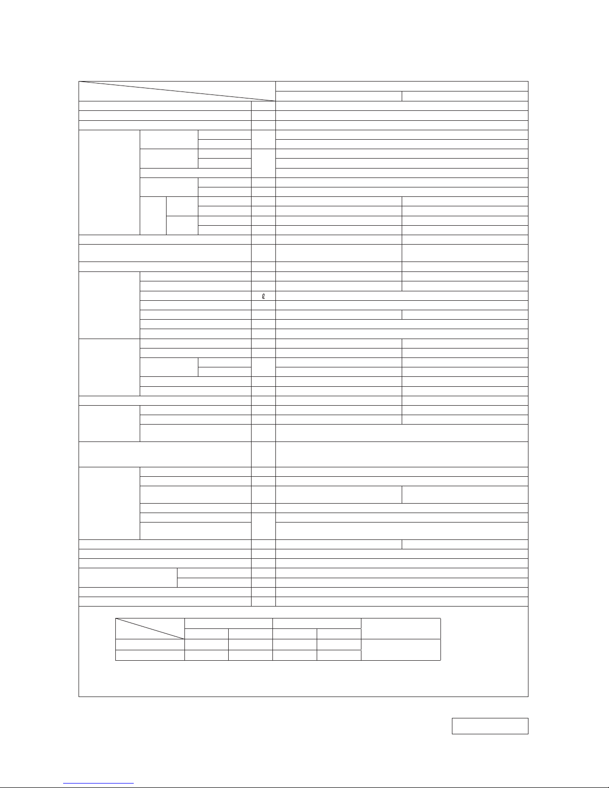
1. SPECIFICATIONS
Model
Item
SRK25ZJP-S
Indoor unit SRK25ZJP-S Outdoor unit SRC25ZJP-S
Cooling capacity (1) W 2500 (1000 (Min.)~2700 (Max.))
Heating capacity (1) W 3200 (1200 (Min.)~4200 (Max.))
Power supply 1 Phase, 220~240 V, 50Hz
Operation
data (1)
Power
consumption
Cooling
kW
0.71 (0.21~0.88)
Heating 0.86 (0.27~1.46)
Running
current
Cooling
A
3.6 / 3.4 / 3.3 (220/ 230/ 240 V)
Heating 4.2 / 4.0 / 3.9 (220/ 230/ 240 V)
Inrush current 4.2 / 4.0 / 3.9 (220/ 230/ 240 V)
COP
Cooling 3.52
Heating 3.72
Noise
level
Cooling
Sound level dB(A) Hi : 36 Me : 30 Lo : 22 46
Power level dB 52 56
Heating
Sound level dB(A) Hi : 35 Me : 30 Lo : 26 48
Power level dB 51 58
Exterior dimensions (Height x Width x Depth) mm 268 x 790 x 224 540 x 780 (+62) x 290
Exterior appearance
(Munsell color)
Fine snow
(8.0Y 9.3/0.1) near equivalent
Stucco white
(4.2Y 7.5/1.1) near equivalent
Net weight kg 8.5 32
Refrigerant
equipment
Compressor type & Q'ty — RM-B5077MDE1 (Rotary type) x 1
Motor (Starting method) kW — 0.75 (Line starting)
Refrigerant oil 0.35 (DIAMOND FREEZE MA68)
Refrigerant (3) kg R410A 0.75 (Pre-Charged up to the piping length of 10m)
Heat exchanger Louver fins & inner grooved tubing M fins & inner grooved tubing
Refrigerant control Capillary tubes + Electronic expansion valve
Deice control Microcomputer control
Air handling
equipment
Fan type & Q'ty Tangential fan x 1 Propeller fan x 1
Motor W 38 24
Air flow
Cooling
CMM
Hi : 8.0 Me : 6.2 Lo : 4.5 29.5
Heating Hi : 9.3 Me : 7.8 Lo : 6.6 25.6
Fresh air intake Not possible —
Air filter, Quality / Quantity Polypropylene net (washable) x 2 —
Shock & vibration absorber — Cushion rubber (for compressor)
Operation
control
Operation switch Wireless-Remote control —
Room temperature control Microcomputer thermostat —
Operation Display
RUN : Green, TIMER : Yellow, HI POWER : Green,
ECONO : Orange
Safety devices
Compressor overheat protection, Overcurrent protection,
Frost protection, Serial signal error protection, Fan motor error protection,
Heating overload protection (High pressure control), Cooling overload protection
Installation
data
Refrigerant piping size (O.D) mm Liquid line: φ6.35 (1/4") Gas line: φ9.52 (3/8")
connecting method Flare connecting
Attached length of piping m
Liquid line : 0.4
Gas line : 0.33
—
Insulation for piping Necessary (Both sides), independent
Refrigerant line (one way) length
m
Max. 15
Vertical height difference between
outdoor unit and indoor unit
Max.10 (Outdoor unit is higher)
Max.10 (Outdoor unit is lower)
Drain hose Connectable (VP 16) —
Power cable 2m (3 Cores wih Earth)
Recommended breaker size A 16
Connection wiring
Size x Core number 1.5mm2 x 4 cores (Including earth cable)
Connecting method Terminal block (Screw fixing type)
Accessories (included)
Mounting kit
Optional parts —
Note (1) The data are measured at the following conditions.
Item
Operation
Indoor air temperature Outdoor air temperature
Standards
DB WB DB WB
Cooling 27˚C 19˚C 35˚C 24˚C
ISO-T1, JIS C 9612
Heating 20˚C — 7˚C 6˚C
(2) This air-conditioner is manufactured and tested in conformity with the ISO.
(3) The operation data are applied to the 220/230/240V districts respectively.
(4) The refrigerant quantity to be charged includes the refrigerant in 10m connecting piping.
(Purging is not required even for the short piping.)
The pipe length is 7.5m.
Adapted to RoHS directive

-
4
-
'10 • SRK-T-100
Model
Item
SRK35ZJP-S
Indoor unit SRK35ZJP-S Outdoor unit SRC35ZJP-S
Cooling capacity (1) W 3500 (1000 (Min.)~3700 (Max.))
Heating capacity (1) W 4000 (1300 (Min.)~4800 (Max.))
Power supply 1 Phase, 220~240 V, 50Hz
Operation
data (1)
Power
consumption
Cooling
kW
1.06 (0.21~1.24)
Heating 1.09 (0.29~1.58)
Running
current
Cooling
A
5.1 / 4.9 / 4.6 (220/ 230/ 240 V)
Heating 5.2 / 5.0 / 4.8 (220/ 230/ 240 V)
Inrush current 5.2 / 5.0 / 4.8 (220/ 230/ 240 V)
COP
Cooling 3.30
Heating 3.67
Noise
level
Cooling
Sound level dB(A) Hi : 39 Me : 32 Lo : 23 49
Power level dB 54 59
Heating
Sound level dB(A) Hi : 41 Me : 36 Lo : 27 51
Power level dB 57 61
Exterior dimensions (Height x Width x Depth) mm 268 x 790 x 224 540 x 780 (+62) x 290
Exterior appearance
(Munsell color)
Fine snow
(8.0Y 9.3/0.1) near equivalent
Stucco white
(4.2Y 7.5/1.1) near equivalent
Net weight kg 8.5 35
Refrigerant
equipment
Compressor type & Q'ty — RM-B5077MDE1 (Rotary type) x 1
Motor (Starting method) kW — 0.90 (Line starting)
Refrigerant oil 0.35 (DIAMOND FREEZE MA68)
Refrigerant (3) kg R410A 1.05 (Pre-Charged up to the piping length of 15m)
Heat exchanger Slit fins & inner grooved tubing M fins & inner grooved tubing
Refrigerant control Capillary tubes + Electronic expansion valve
Deice control Microcomputer control
Air handling
equipment
Fan type & Q'ty Tangential fan x 1 Propeller fan x 1
Motor W 38 24
Air flow
Cooling
CMM
Hi : 8.5 Me : 6.8 Lo : 4.6 27.8
Heating Hi : 11.0 Me : 8.4 Lo : 6.8 27.8
Fresh air intake Not possible —
Air filter, Quality / Quantity Polypropylene net (washable) x 2 —
Shock & vibration absorber — Cushion rubber (for compressor)
Operation
control
Operation switch Wireless-Remote control —
Room temperature control Microcomputer thermostat —
Operation Display
RUN : Green, TIMER : Yellow, HI POWER : Green,
ECONO : Orange
Safety devices
Compressor overheat protection, Overcurrent protection,
Frost protection, Serial signal error protection, Fan motor error protection,
Heating overload protection (High pressure control), Cooling overload protection
Installation
data
Refrigerant piping size (O.D) mm Liquid line :φ6.35 (1/4") Gas line :φ9.52 (3/8")
connecting method Flare connecting
Attached length of piping m
Liquid line : 0.40
Gas line : 0.33
—
Insulation for piping Necessary (Both sides), independent
Refrigerant line (one way) length
m
Max. 15
Vertical height difference between
outdoor unit and indoor unit
Max.10 (Outdoor unit is higher)
Max.10 (Outdoor unit is lower)
Drain hose Connectable (VP 16) —
Power cable 2m (3 Cores wih Earth)
Recommended breaker size A 16
Connection wiring
Size x Core number 1.5mm2 x 4 cores (Including earth cable)
Connecting method Terminal block (Screw fixing type)
Accessories (included) Mounting kit
Optional parts —
Adapted to RoHS directive
RWA000Z232
Note (1) The data are measured at the following conditions.
Item
Operation
Indoor air temperature Outdoor air temperature
Standards
DB WB DB WB
Cooling 27˚C 19˚C 35˚C 24˚C
ISO-T1 , JIS C 9612
Heating 20˚C — 7˚C 6 ˚C
(2) This air-conditioner is manufactured and tested in conformity with the ISO.
(3) The operation data are applied to the 220/230/240V districts respectively.
(4) The refrigerant quantity to be charged includes the refrigerant in 15m connecting piping.
(Purging is not required even for the short piping.)
The pipe length is 7.5m.
-
5
-
'10 • SRK-T-100
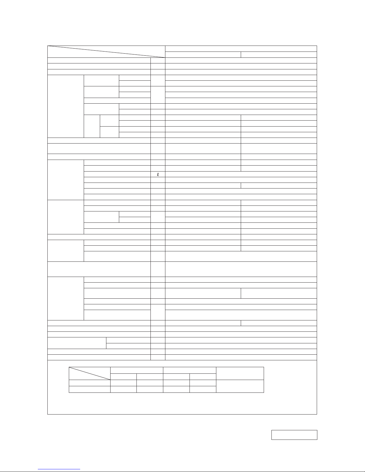
Model
Item
SRK50ZJP-S
Indoor unit SRK50ZJP-S Outdoor unit SRC50ZJP-S
Cooling capacity (1) W 5000 (1600 (Min.)~5500 (Max.))
Heating capacity (1) W 5800 (1600 (Min.)~6600 (Max.))
Power supply 1 Phase, 220~240 V, 50Hz
Operation
data (1)
Power
consumption
Cooling
kW
1.56 (0.40~2.20)
Heating 1.60 (0.42~2.10)
Running
current
Cooling
A
7.2 / 6.9 / 6.6 (220/ 230/ 240 V)
Heating 7.3 / 7.0 / 6.7 (220/ 230/ 240 V)
Inrush current 7.3 / 7.0 / 6.7 (220/ 230/ 240 V)
COP
Cooling 3.21
Heating 3.63
Noise
level
Cooling
Sound level dB(A) Hi : 47 Me : 37 Lo : 26 51
Power level dB 63 61
Heating
Sound level dB(A) Hi : 47 Me : 40 Lo : 33 53
Power level dB 62 63
Exterior dimensions (Height x Width x Depth) mm 268 x 790 x 224 640 x 800 (+71) x 290
Exterior appearance
(Munsell color)
Fine snow
(8.0Y 9.3/0.1) near equivalent
Stucco white
(4.2Y 7.5/1.1) near equivalent
Net weight kg 8.5 42
Refrigerant
equipment
Compressor type & Q'ty — 5RS132XAB21 (Rotary type) x 1
Motor (Starting method) kW — 1.50 (Line starting)
Refrigerant oil 0.37 (FV50S)
Refrigerant (3) kg R410A 1.35 (Pre-Charged up to the piping length of 15m)
Heat exchanger Slit fins & inner grooved tubing M fins & inner grooved tubing
Refrigerant control Capillary tubes + Electronic expansion valve
Deice control Microcomputer control
Air handling
equipment
Fan type & Q'ty Tangential fan x 1 Propeller fan x 1
Motor W 38 34
Air flow
Cooling
CMM
Hi : 11.0 Me : 7.6 Lo : 4.7 36.0
Heating Hi : 13.8 Me : 10.7 Lo : 8.3 36.0
Fresh air intake Not possible —
Air filter, Quality / Quantity Polypropylene net (washable) x 2 —
Shock & vibration absorber — Cushion rubber (for compressor)
Operation
control
Operation switch Wireless-Remote control —
Room temperature control Microcomputer thermostat —
Operation Display
RUN : Green, TIMER : Yellow, HI POWER : Green,
ECONO : Orange
Safety devices
Compressor overheat protection, Overcurrent protection,
Frost protection, Serial signal error protection, Fan motor error protection,
Heating overload protection (High pressure control), Cooling overload protection
Installation
data
Refrigerant piping size (O.D) mm Liquid line :φ6.35 (1/4") Gas line :φ12.7 (1/2")
connecting method Flare connecting
Attached length of piping m
Liquid line : 0.4
Gas line : 0.33
—
Insulation for piping Necessary (Both sides), independent
Refrigerant line (one way) length
m
Max. 25
Vertical height difference between
outdoor unit and indoor unit
Max. 15 (Outdoor unit is higher)
Max. 15 (Outdoor unit is lower)
Drain hose Connectable (VP 16) —
Power cable 2m (3 Cores wih Earth)
Recommended breaker size A 16
Connection wiring
Size x Core number 1.5mm2 x 4 cores (Including earth cable)
Connecting method Terminal block (Screw fixing type)
Accessories (included) Mounting kit
Optional parts —
Adapted to RoHS directive
RWA000Z232
Note (1) The data are measured at the following conditions.
Item
Operation
Indoor air temperature Outdoor air temperature
Standards
DB WB DB WB
Cooling 27˚C 19˚C 35˚C 24˚C
ISO-T1 , JIS C 9612
Heating 20˚C — 7˚C 6 ˚C
(2) This air-conditioner is manufactured and tested in conformity with the ISO.
(3) The operation data are applied to the 220/230/240V districts respectively.
(4) The refrigerant quantity to be charged includes the refrigerant in 15m connecting piping.
(Purging is not required even for the short piping.)
The pipe length is 7.5m.
-
6
-
'10 • SRK-T-100
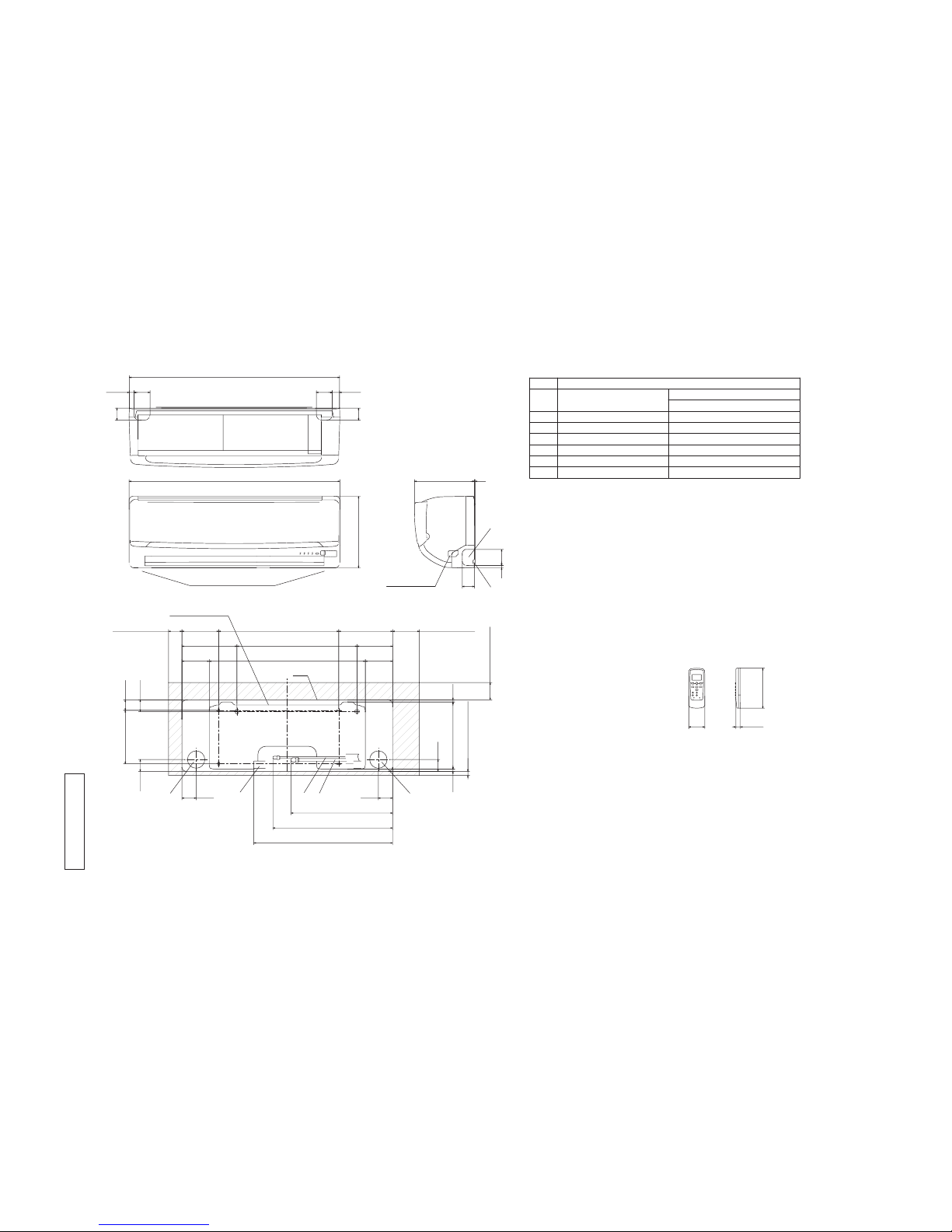
2. EXTERIOR DIMENSIONS
(1) Indoor units
Models SRK25ZJP-S, 35ZJP-S, 50ZJP-S
RKX0 00Z50 7
G
Terminal block
F
Wireless remote controller
Outlet for down piping
㧔Refer to the above view㧕
Space for installation and service when viewing from the front
D A
B
E
C
Hole on wall for right rear piping
Hole on wall for left rear piping
Gas piping
Outlet for wiring
Drain hose
Liquid piping
F
E
C
D
B
Symbol
A
㧔Ǿ65㧕
VP16
Ǿ6.35㧔1㧛4"㧕㧔Flare㧕
Content
㧔Ǿ65㧕
Ǿ9.52㧔3㧛8"㧕㧔Flare㧕
Outlet for piping㧔on both side㧕
G
Ǿ12.7㧔1㧛2"㧕㧔Flare㧕
Model 25,35
Model 50
Note㧔1㧕The model name label is attached
ޓޓޓon the underside of the panel.
60
150
17.3
788
2760
45
60
45
790
268
17.5
3224
45
609
200
39.3
43.244.5
102.5 585 102.5
206.5 450 133.5
138 450 202
44.5
7.5252.28.3
㧔Service space㧕
65
㧔Service space㧕
15
50
㧔
Service space
㧕
100
㧔Service space㧕
53.5
380.6
448.6
520
53.5
Installation plate
Unit
Unit:mm
-
7
-
'10 • SRK-T-100
A
RCV0 00Z00 6
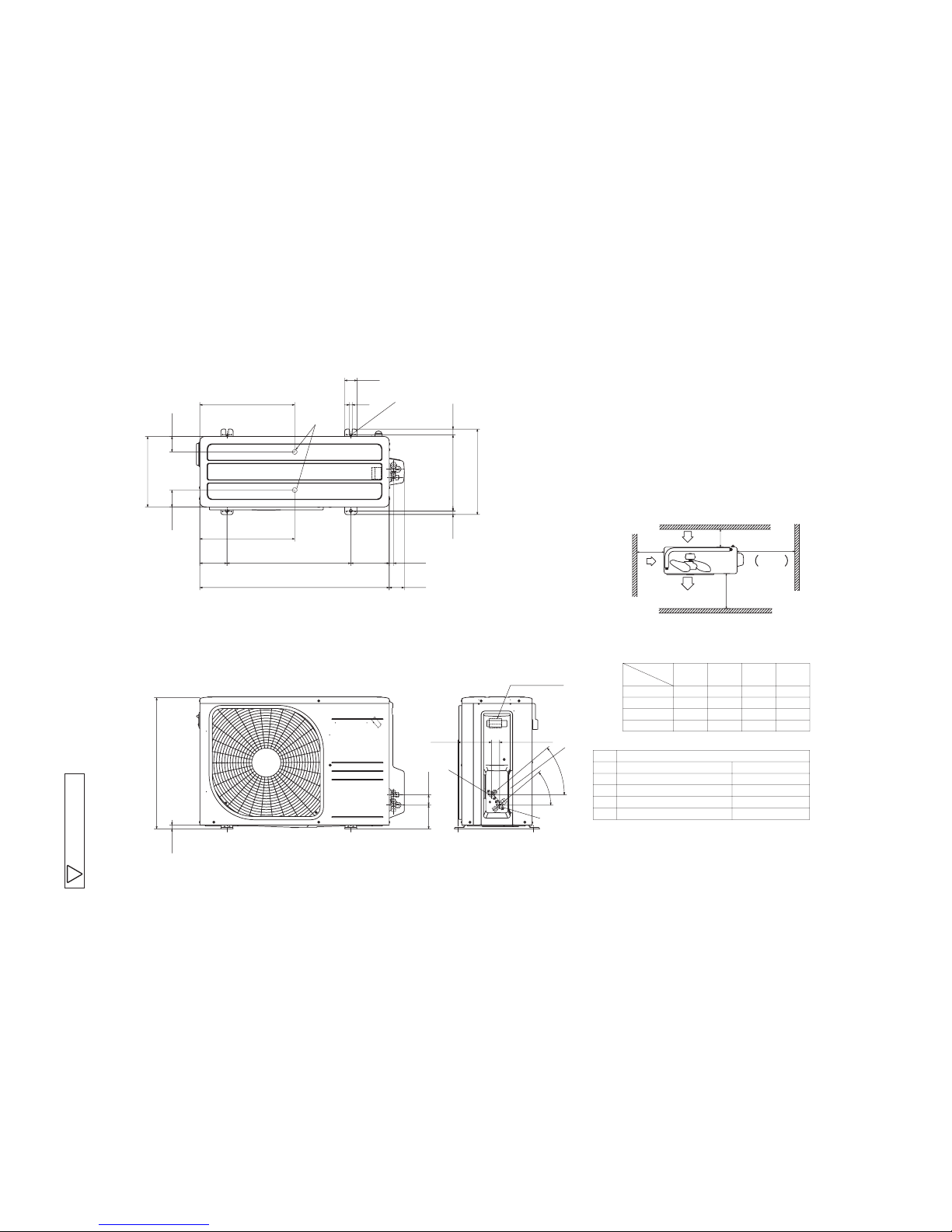
(2) Outdoor units
Models SRC25ZJP-S, 35ZJP-S
Notes
㧔1㧕 It must not be surrounded by walls on the four sides.
㧔2㧕 The unit must be fixed with anchor bolts. An anchor bolt must not
protrude more the 15mm.
㧔3㧕 Where the unit is subject to strong winds, lay it in such
a direction that the blower outlet faces perpendicularly
to the dominant wind direction.
㧔4㧕 Leave 1m or more space above the unit.
㧔5㧕 A wall in front of the blower outlet must not exceed the units height.
㧔6㧕 The model name label is attached on the lower right comer of the front panel.
L4
L3
L1
Intake
Service
space
Intake
Outlet
Minimum installation space
L2
L2
L3
L4
L1
100
100
250
Open
㧵 㧵㧵
Open
250
80
280
㧵㧵㧵
280
Open
80
75
Examples of
Dimensions
installation
㧵㨂
180
Open
80
Open
Ǿ9.52㧔3㧛8"㧕㧔Flare㧕
Content
C Pipe㧛cable draw-out hole
D
E Anchor bolt hole
Drain discharge hole
Symbol
B
A Service valve connection㧔gas side㧕
M10 × 4places
Ǿ20 × 2places
Service valve connection㧔liquid side㧕
Ǿ6.35㧔1㧛4"㧕㧔Flare㧕
Unit:mm
A
C
Terminal block
B
40°
40°
33.5
138.4
97.7
15.8
540
290
42.5
69.4
63.4
390.6
390.6
111.6 510
158.4
12
50.6
17.9
780 61.9
312.5
351.6
14.8 24.3
D
E

-
8
-
'10 • SRK-T-100
Model SRC50ZJP-S
RC T 000Z 005
L2
Intake
Outlet
Intake
L3
L1
Minimum installation space
Service
space
( )
L4
L2
L3
L4
L1
100
100
250
Open
I II
Open
250
80
280
III
280
Open
80
75
Examples of
Dimensions
installation
IV
180
Open
80
Open
φ12.7(1/2")(Flare)
Content
C Pipe/cable draw-out hole
D
E Anchor bolt hole
Drain discharge hole
Symbol
B
A Service valve connection(gas side)
M10 × 4places
φ20 × 5places
Service valve connection(liquid side)
φ6.35(1/4")(Flare)
Notes
(1) It must not be surrounded by walls on the four sides.
(2) The unit must be fixed with anchor bolts. An anchor bolt must not
protrude more the 15mm.
(3) Where the unit is subject to strong winds, lay it in such
a direction that the blower outlet faces perpendicularly
to the dominant wind direction.
(4) Leave 1m or more space above the unit.
(5) A wall in front of the blower outlet must not exceed the units height.
(6) The model name label is attached on the right side of the unit.
A
C
Terminal block
B
93 42.5
640
800
89 510 201
327.3
83.5
290
43.5
327.3 50.6
12
24.3312.514.8
71.2
17.9
40°
40°
33.5148.4
12.4
351.6
38.6
90.6
520.6 161
35.6
D
E
Unit:mm
-
9
-
'10 • SRK-T-100
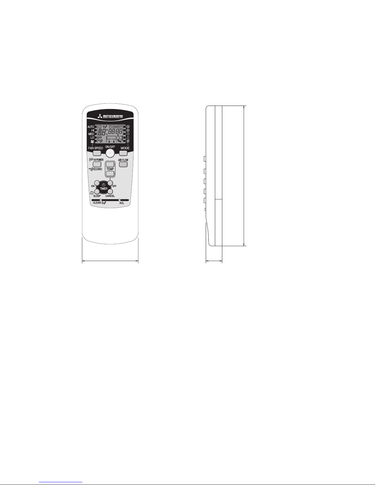
(3) Wireless remote controller
Unit: mm
60
17.3
150
-
10
-
'10 • SRK-T-100
3. ELECTRICAL WIRING
(1) Indoor units
Models SRK25ZJP-S, 35ZJP-S, 50ZJP-S
RW A 000Z 228
G
J
R-AMP
WIRELESS
DISPLAY
N
CNGCNE
250V 3.15A
CNU
CNM
52C
52C-3
52C-4
BACK UP SW
5
U
M
M
CNF
FMSM
HD
F
Va
DS
T
※
Blue
BlackBK
Red
BL
RD
WhiteWH
Yellow/Green
Y/G
ColorMark
Heat exch. sensor
Fan motor
Room temp. sensor
Flap motor
Diode stackDS
FuseF
Connector
CNE-CNU
FM
Terminal blockT
Description
Item
VaristorVa
SM
ThI
Th2
YellowY
Humidity sensor
HD
BrownBR
Light blueLB
BR
Y/G
RD
Y
WH
Y/G
RD
BK
BOX
CONTROL
3
2/N
WH
6
TO OUTDOOR UNIT
1
BOARD
PRINTED CIRCUIT
~220/230/240V 50Hz
POWER SOURCE
BR
LB
Y/G
BK
1 3 4 5
RDBKBL
EXCHANGER
HEAT
WH
8 2 2 2
t゜
※SRK35, 50 MODELS ONLY
ThI Th2
t゜

-
11
-
'10 • SRK-T-100
RW C 000Z 236
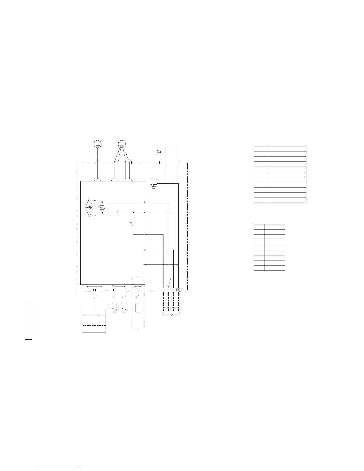
(2) Outdoor units
Models SRC25ZJP-S, 35ZJP-S
3
1
2
[
]
N
(BK)
C-2
G1
(RD)
(Y/G)
S.IN
(WH)
R.IN
(BK)
(WH)
(RD)
PWB ASSY
250V 20A
F2
F3 250V 1A
++
F4
250V 10A
F1
250V 2A
CIRCUIT
PAM
SWITCHING POWER
CIRCUIT
N
P
W
V
U
TRANSISTOR
POWER
W
V
U
FILTER
NOISE
CN20S
CNTH
CNEEV
CNFAN
M
M
3~
250V 15A
(Y/G)
T1
T2
(OR)
(Y)
M
t゜
20S
TH1TH2 TH3
EEV
FMo
CM
t゜ t゜
t゜
L
TERMINAL
N
1
3
2
BLOCK
T
TO INDOOR UNIT
POWER WIRES
SIGNAL WIRE
POWER SOURCE
~220/230/240V 50Hz
Color
RD
Mark
OrangeOR
Yellow/Green
Y/G
BlackBK
YellowY
WhiteWH
Red
DescriptionItem
Connector
Electric expansion valve(coil)EEV
Fan motorFMo
ReactorL
Terminal blockT
Compressor motorCM
Solenoid valve for 4 way valve20S
Heat exchanger sensor(outdoor unit)TH1
Outdoor air temp.sensorTH2
TH3 Discharge pipe temp.sensor
CN20S
CNTH
CNEE
-
12
-
'10 • SRK-T-100
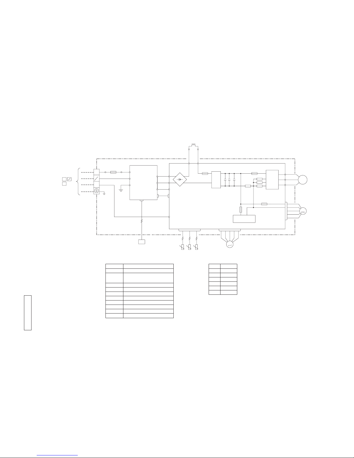
RW C 000Z 237
Model SRC50ZJP-S
3
1
2
[
]
N
M
T2
T1
S
(BK)
(WH)
(RD)
V
W
U
PWB ASSY (MAIN)
M
M
+ +
R
TRANSISTOR
POWER
CIRCUIT
SWITCHING POWER
250V 2A
F1
250V 20A
F2
F3 250V 1A
W
V
U
P
NU
NV
NW
CNTH
CNEEV
CNFAN
t゜
3~
+
ACTIVE
FILTER
UNIT
250V 20A
F8
(OR)
(Y)
S-2
t゜ t゜
(BK)
(WH)
(WH)
(BK)
PWB ASSY (SUB)
S-1
CNSUB
CNMAIN
S
R
(BK)
(WH)
G1
(Y/G)
IN
IN
S
R
O
O
250V 20A
FUSE
2
1
N
3
(Y/G)
CN20S
C-2
(RD)
20S
(RD)
T
TERMINAL
TH1 TH2 TH3
EEV
FMo
CM
BLOCK
L
TO INDOOR UNIT
POWER WIRES
SIGNAL WIRE
POWER SOURCE
~220/230/240V 50Hz
Color
RD
Mark
OrangeOR
Yellow/Green
Y/G
BlackBK
YellowY
WhiteWH
Red
DescriptionItem
Connector
Electric expansion valve(coil)EEV
Fan motorFMo
ReactorL
Terminal blockT
Compressor motorCM
Solenoid valve for 4 way valve20S
Heat exchanger sensor(outdoor unit)TH1
Outdoor air temp.sensorTH2
TH3 Discharge pipe temp.sensor
CN20S
CNTH
CNEE
-
13
-
'10 • SRK-T-100
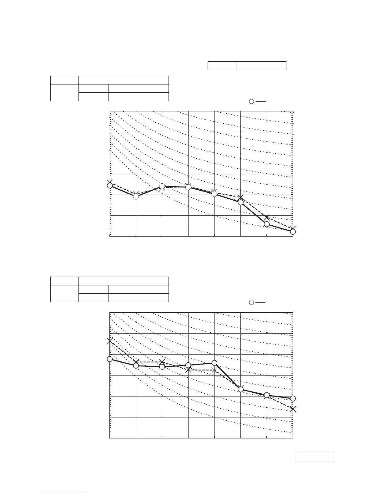
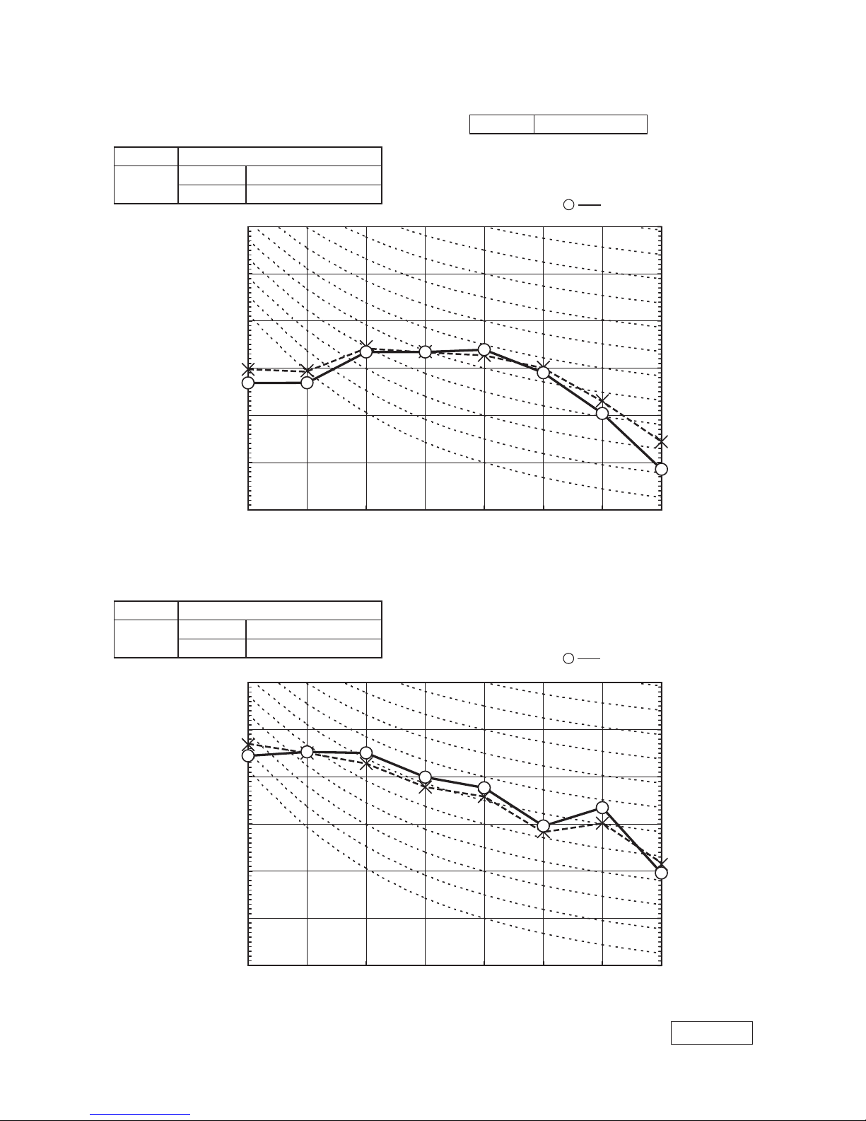
(Outdoor Unit)
Model SRC25ZJP-S
Noise
Level
Cooling 46 dB(A)
Heating 48 dB(A)
(Indoor Unit)
Model SRK25ZJP-S
Noise
Level
Cooling 36 dB(A)
Heating 35 dB(A)
×
......
Cooling, Heating
×
......
Cooling, Heating
Condition ISO-T1,JIS C9612
4. NOISE LEVEL
Model SRK25ZJP-S
10
20
30
40
50
60
70
63 125 250 500 1000 2000 4000 8000
10
20
30
40
50
60
70
N50
N30
N40
N60
N70
N20
N50
N30
N40
N60
N70
N20
Sound Pressure Level (dB)
(standard 2×10
-5
Pa )
Mid Octave Band frequency (Hz)
10
20
30
40
50
60
70
63 125 250 500 1000 2000 4000 8000
10
20
30
40
50
60
70
Sound Pressure Level (dB)
(standard 2×10
-5
Pa )
Mid Octave Band frequency (Hz)
ISC09164

-
14
-
'10 • SRK-T-100
(Outdoor Unit)
Model SRC35ZJP-S
Noise
Level
Cooling 49 dB(A)
Heating 51 dB(A)
(Indoor Unit)
Model SRK35ZJP-S
Noise
Level
Cooling 39 dB(A)
Heating 41 dB(A)
×
......
Cooling, Heating
×
......
Cooling, Heating
Condition ISO-T1,JIS C9612
Model SRK35ZJP-S
10
20
30
40
50
60
70
63 125 250 500 1000 2000 4000 8000
10
20
30
40
50
60
70
Sound Pressure Level (dB)
(standard 2×10
-5
Pa )
Mid Octave Band frequency (Hz)
10
20
30
40
50
60
70
63 125 250 500 1000 2000 4000 8000
10
20
30
40
50
60
70
Sound Pressure Level (dB)
(standard 2×10
-5
Pa )
Mid Octave Band frequency (Hz)
N50
N30
N40
N60
N70
N20
N50
N30
N40
N60
N70
N20
ISC09164
-
15
-
'10 • SRK-T-100
(Indoor Unit)
Model SRK50ZJP-S
Noise
Level
Cooling 47 dB(A)
Heating 47 dB(A)
×
......
Cooling, Heating
×
......
Cooling, Heating
Condition ISO-T1,JIS C9612
Model SRK50ZJP-S
N50
N30
N40
N60
N70
N20
N50
N30
N40
N60
N70
N20
10
20
30
40
50
60
70
63 125 250 500 1000 2000 4000 8000
10
20
30
40
50
60
70
Sound Pressure Level (dB)
(standard 2×10
-5
Pa )
Mid Octave Band frequency (Hz)
10
20
30
40
50
60
70
63 125 250 500 1000 2000 4000 8000
10
20
30
40
50
60
70
Sound Pressure Level (dB)
(standard 2×10
-5
Pa )
Mid Octave Band frequency (Hz)
ISC09164
(Outdoor Unit)
Model SRC50ZJP-S
Noise
Level
Cooling 51 dB(A)
Heating 53 dB(A)
-
16
-
'10 • SRK-T-100
'09•SRK-DB-087D
5 PIPING SYSTEM
Models SRK20ZJ-S, 25ZJ-S
Model SRK35ZJ-S
Humidity
sensor
(HD)
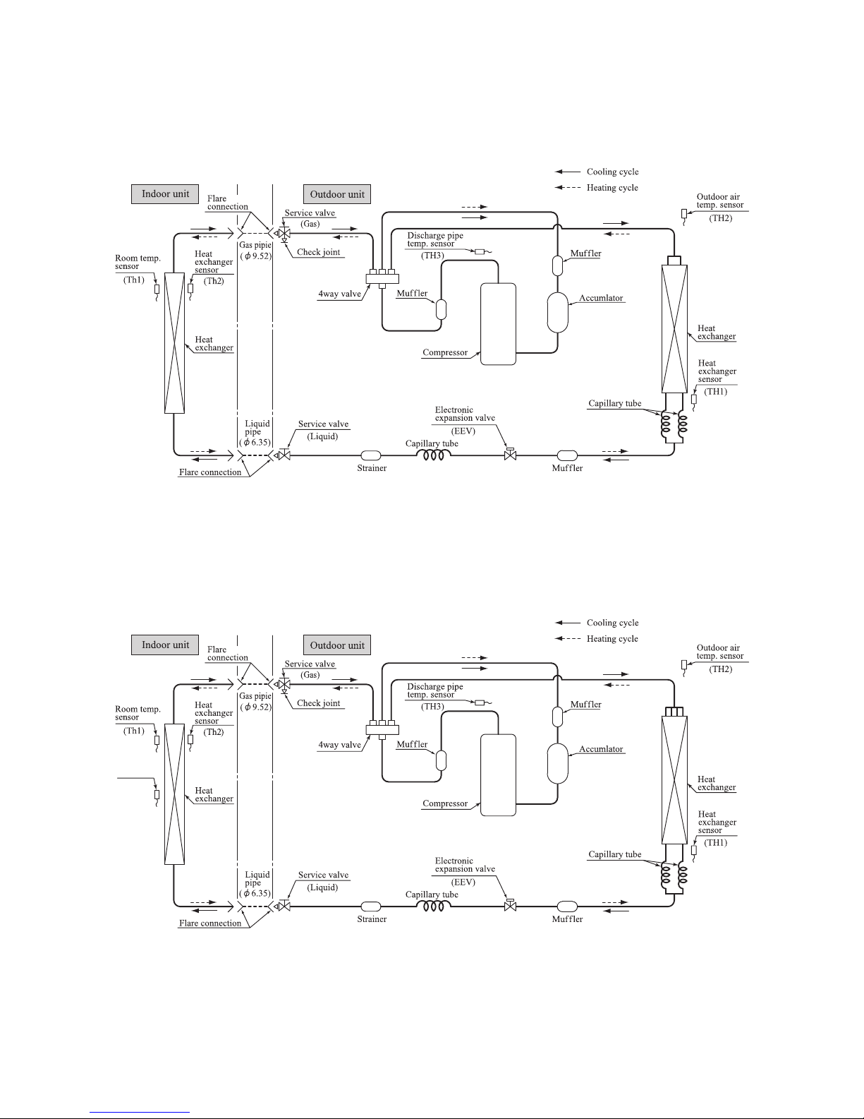
5. PIPING SYSTEM
Model SRK25ZJP-S
Model SRK35ZJP-S
-
17
-
'10 • SRK-T-100
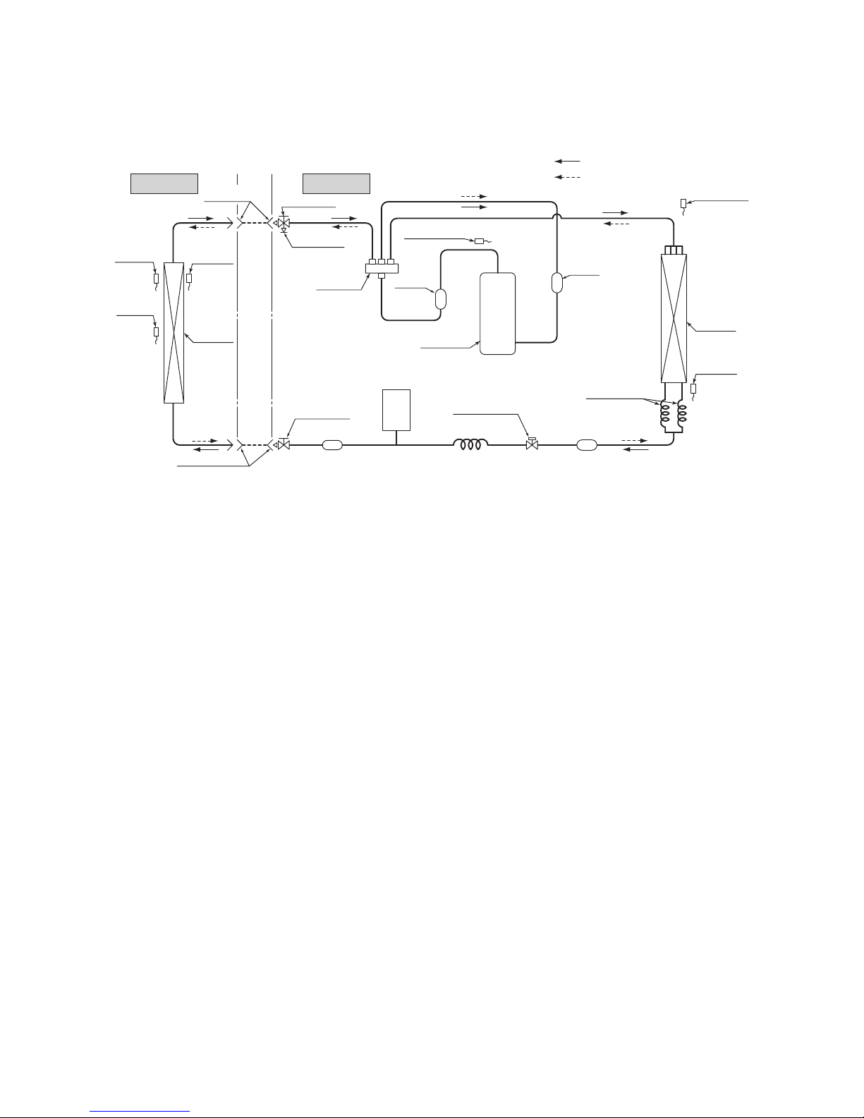
Model SRK50ZJP-S
Indoor unit
Outdoor unit
Flare
connection
Flare connection
Liquid
pipe
(φ6.35)
Gas pipie
(φ12.7)
Service valve
Heat
exchanger
Electronic
expansion valve
(Liquid)
Strainer
Receiver
Muffler
Capillary tube
Outdoor air
temp. sensor
Muffler
Muffler
Compressor
Discharge pipe
temp. sensor
Cooling cycle
Heating cycle
Check joint
4way valve
Service valve
Heat
exchanger
sensor
(Th2)
(TH3)
Room temp.
sensor
(Th1)
(
Gas
)
(TH2)
Heat
exchanger
sensor
(TH1)
(EEV)
Capillary tube
Heat
exchanger
Humidity
sensor
(HD)
 Loading...