

Mitsubishi Heavy Industries SRK20ZIX-S, SRK25ZIX-S, SRK35ZIX-S, SRF25ZIX-S, SRF35ZIX-S Service Manual
...
SERVICE MANUAL
Manual No. '09 •SRK/SRF - SM - 082
INVERTER WALL MOUNTED TYPE
AND FLOOR STANDING TYPE
ROOM AIR-CONDITIONER
( Split system, air to air heat pump type )
Wall mounted type
SRK20ZIX-S
25ZIX-S
35ZIX-S
50ZIX-S
60ZIX-S
Floor standing type
SRF25ZIX-S
35ZIX-S
50ZIX-S
updated 25,May,2009

-
1
-
TABLE OF CONTENTS
1. WALL MOUNTED TYPE(SRK) .................................................................2
2. FLOOR STANDING TYPE(SRF) ............................................................45
3. MAINTENANCE DATA ........................................................................... 69
3.1 Troubleshooting procedures for electrical equipment .................
69
3.2 Servicing .........................................................................................
90
4. REFRIGERANT PIPING INSTALLATION / SERVICING MANUAL
FOR AIR CONDITIONERS USING R410A .............................................
91
4.1 Outline .............................................................................................
91
4.2 Refrigerant piping installation .......................................................
92
4.3 Installation, removal and servicing ...............................................
98
4.4 Refrigerant recovery ....................................................................
103

-
2
-
1. WALL MOUNTED TYPE(SRK)
CONTENTS
1.1 Electrical wiring ....................................................................................3
1.2 Piping system .......................................................................................6
1.3 Noise level ............................................................................................. 7
1.4 Sensible heat capacity .......................................................................12
1.5 Application data ..................................................................................14
1.5.1 Installation of indoor unit ............................................................
14
1.5.2 Installation of outdoor unit ..........................................................
18
1.6 Outline of operation control by microcomputer ..............................33
CONTENTS
1 RANGE OF USAGE & LIMITATIONS .................................................. 1
2 INDOOR UNIT ....................................................................................... 3
2.1 Wall mounted type (SRK) ............................................................ 3
(1) Specifications ........................................................................... 3
(2) Exterior dimensions .................................................................. 8
(3) Electrical wiring ......................................................................... 9
2.2 Floor standing type (SRF) ........................................................... 10
(1) Specifications ...........................................................................10
(2) Exterior dimensions .................................................................. 13
(3) Electrical wiring ........................................................................14
(1) Exterior dimensions .................................................................. 15
(2) Electrical wiring .........................................................................17
3 OUTDOOR UNIT ...................................................................................15
Series code
Inverter type
Product capacity
Wall mounted type
Split type room air-conditioner
■
How to read the model name
Example : SR K 50 Z IX - S
-
3
-
1.1 Electrical wiring
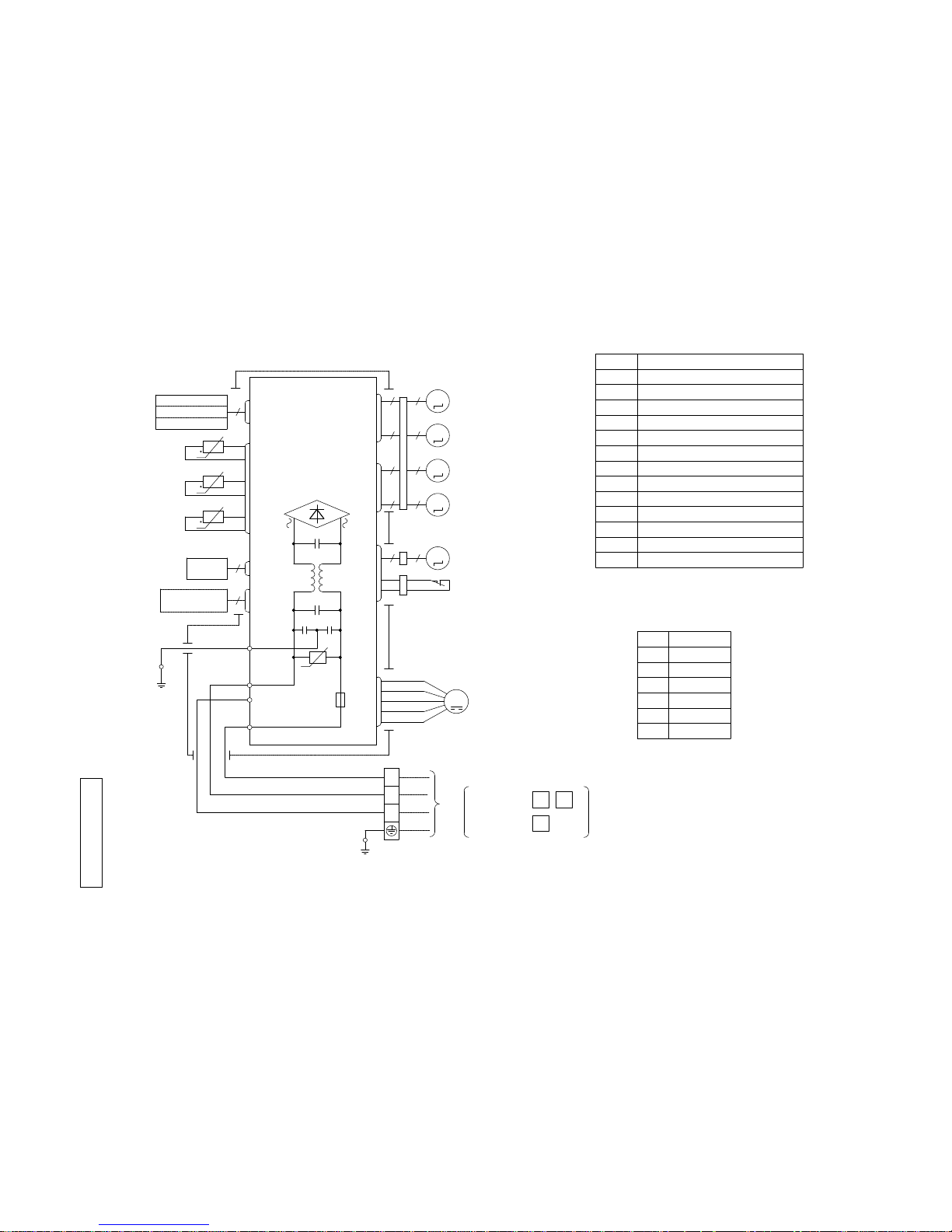
(1) Indoor unit
Models SRK20ZIX-S, 25ZIX-S, 35ZIX-S, 50ZIX-S, 60ZIX-S
RWA 000Z215
250V
F
G
3.15A
S/N
Va
CNU
CNS
INTERFACE KIT
SC-BIKN-E
CNG
CNE
DISPLAY
WIRELESS RECEIVER
J
CNF
U
M
HEAT
1
3
4
5
6
BACK-UP SW
5
2
12
EXCHANGER
L
Th1
BOARD
CIRCUIT
PRINTED
LS
CNY
CNX2
CNX1
M
M
M
M
M
5
5
5
5
5
5
5
5
5 5
IM
RD
WH
RD
WH
BK
BL
Y
Y/G
BK
t
Th21
Th22
Th3
LM1
LM2
SM1
SM2
FMI
DS
t
t
TO OUTDOOR UNIT
HEAT
EXCHANGER
1
2/N
3
POWER WIRES
SIGNAL WIRE
1
2/N
3
Power source
1 phase 220 - 240 V 50Hz
T
Color Marks
Blue
BlackBK
Red
BL
RD
WhiteWH
Yellow/Green
Y/G
YellowY
ColorMark
Heat exch. sensor
Humidity sensor (50,60 only)
Fan motor
Room temp. sensor
Flap motor
Th1
Th21,2
Th3
Diode stackDS
FuseF
Connector
CNE-CNY
FMI
Terminal blockT
Louver motor
LM1,2
SM1,2
Limit switchLS
Inlet motor
IM
Description
Item
VaristorVa
-
4
-
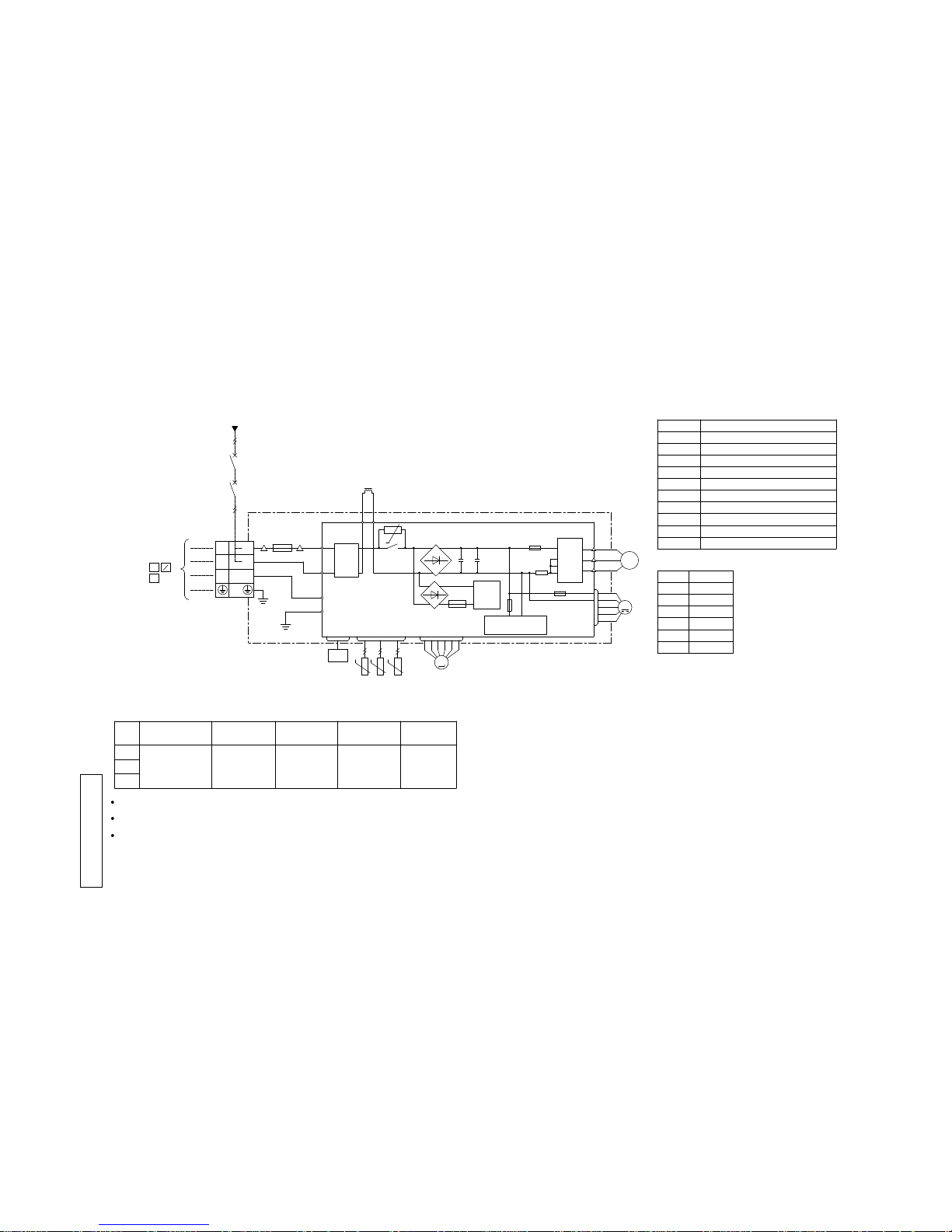
(2) Outdoor unit
Models SRC20ZIX-S, 25ZIX-S, 35ZIX-S
RW C0 00Z213
Color
RD
Mark
OrangeOR
Yellow/Green
Y/G
BlackBK
YellowY
WhiteWH
Red
DescriptionItem
Connector
CNEEV~20S
Electric expansion valve(coil)
EEV
Fan motor
FMo
Reactor
L
Terminal block
T
Compressor motor
CM
Solenoid valve for 4 way valve
20S
Heat exchanger sensor(outdoor unit)
TH1
Outdoor air temp.sensor
TH2
TH3
Discharge pipe temp.sensor
20
Model
Power cable, indoor-outdoor connecting wires
The specifications shown in the above table are for units without heaters. For units with heaters, refer
to the installation instructions or the construction instructions of the indoor unit.
Switchgear of Circuit breaker capacity which is calculated from MAX. over current should be chosen
along the regulations in each country.
The cable specifications are based on the assumption that a metal or plastic conduit is used with no
more than three cables contained in a conduit and a voltage drop is 2%. For an installation falling
outside of these conditions, please follow the internal cabling regulations. Adapt it to the regulation
in effect in each country.
25 8 2.0 32
φ1.6mm x 3 φ1.6mm
35
3
1
2
[ ]
N
POWER SOURCE 1~220ー240V 50Hz/1~220V 60Hz
(BK)
C-2G1(RD)
(Y/G)
S.IN
(WH)
TERMINAL
R.IN
(BK)
(WH)
(RD)
PWB ASSY
250V 20A
F2
F3 250V 1A
F4
250V 10A
F1
250V 2A
CIRCUIT
PAM
SWITCHING POWER
CIRCUIT
NW
NV
NU
P
W
V
U
TRANSISTOR
POWER
W
V
U
FILTER
NOISE
CN20S
CNTH
CNEEV
CNFAN
M
M
3~
250V 15A
L
(Y/G)
N
1
3
2
T1
T2
(OR)
(Y)
BLOCK
M
t゜
20S
TH1 TH2 TH3
EEV
FMo
CM
t゜ t゜
t゜
T
L
TO INDOOR UNIT
POWER WIRES
SIGNAL WIRE
MAX running current
Power cable size
(mm )
(A)
Power cable length
(m)
indoor-outdoor
wire size x number
Earth wire size
(mm)
2
-
5
-
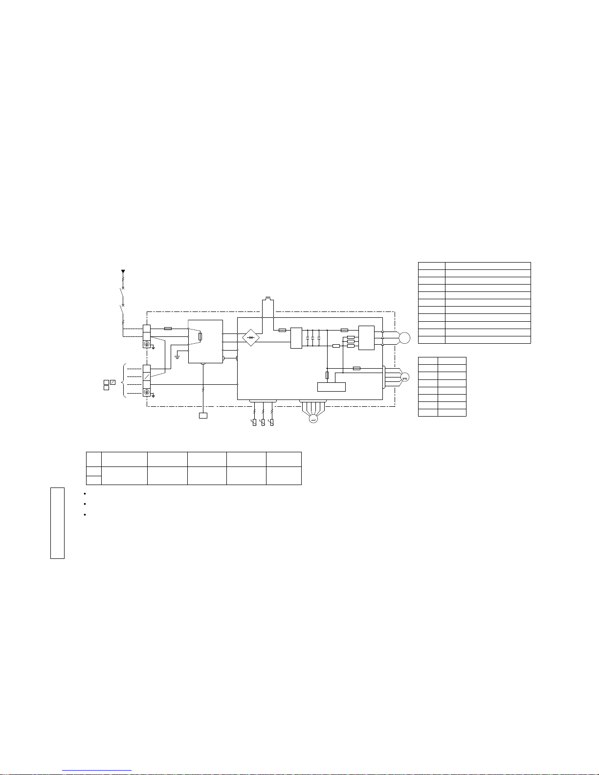
Models SRC50ZIX-S, 60ZIX-S
RW C0 00Z214
Color
RD
Mark
OrangeOR
Yellow/Green
Y/G
BlackBK
BrownBR
YellowY
WhiteWH
Red
DescriptionItem
Connector
CNEEV~20S
Electric expansion valve(coil)
EEV
Fan motor
FMo
Reactor
L
Terminal block
T1,2
Compressor motor
CM
Solenoid valve for 4 way valve
20S
Heat exchanger sensor(outdoor unit)
TH1
Outdoor air temp.sensor
TH2
TH3
Discharge pipe temp.sensor
POWER SOURCE 1~220ー240V 50Hz/1~220V 60Hz
Model
Power cable, indoor-outdoor connecting wires
The specifications shown in the above table are for units without heaters. For units with heaters, refer
to the installation instructions or the construction instructions of the indoor unit.
Switchgear of Circuit breaker capacity which is calculated from MAX. over current should be chosen
along the regulations in each country.
The cable specifications are based on the assumption that a metal or plastic conduit is used with no
more than three cables contained in a conduit and a voltage drop is 2%. For an installation falling
outside of these conditions, please follow the internal cabling regulations. Adapt it to the regulation
in effect in each country.
14 2.0 18 φ1.6mm x 3 φ1.6mm
50
3
1
2
[ ]
N
60
M
T2
T1
S
(BK)
(WH)
(RD)
V
W
U
PWB ASSY (MAIN)
M
M
R
TRANSISTOR
POWER
CIRCUIT
SWITCHING POWER
250V 2A
F1
250V 20A
F2
F3 250V 1A
W
V
U
P
NU
NV
NW
CNTH
CNEEV
CNFAN
t゜
3~
ACTIVE
FILTER
UNIT
250V 20A
F8
(OR)
(Y)
S-2
t゜ t゜
(BK)
(WH)
(WH)
(BK)
PWB ASSY (SUB)
S-1
CNSUB
CNMAIN
250V 10A
F10
S
R
R
(BK)
(WH)
G1
(Y/G)
(BR)
IN
IN
OUT
S
R
O
O
N
L
250V 20A
FUSE
2
1
N
3
(Y/G)
(Y/G)
CN20S
C-2
(RD)
20S
(RD)
T1
T2
TERMINAL
BLOCK
TH1 TH2 TH3
EEV
FMo
CM
BLOCK
TERMINAL
(WH)
TO INDOOR UNIT
POWER WIRES
SIGNAL WIRE
L
MAX running current
Power cable size
(mm )
(A)
Power cable length
(m)
indoor-outdoor
wire size x number
Earth wire size
(mm)
2
-
6
-
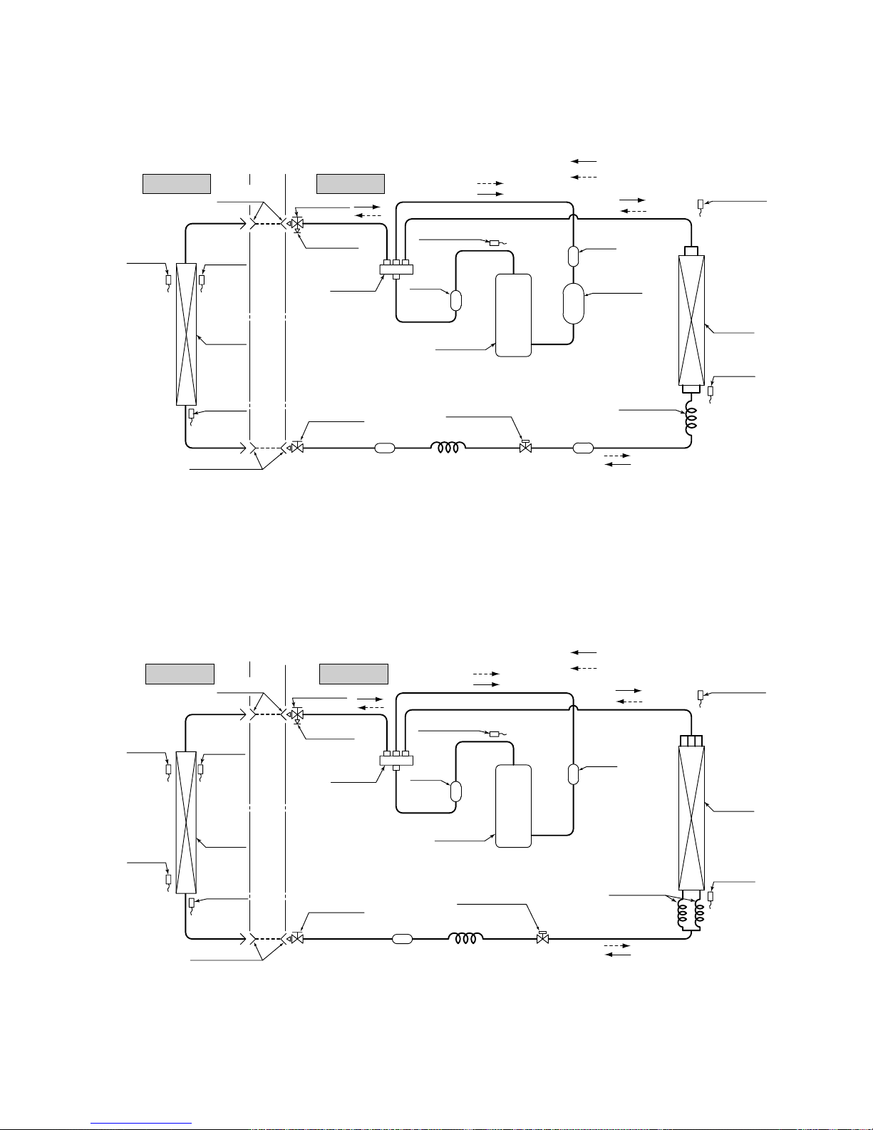
1.2 Piping system
Model SRK20ZIX-S, 25ZIX-S, 35ZIX-S
Heat
exchanger
sensor
(Th22)
4way valve
Service valve
(
Gas
)
Models SRK50ZIX-S,60ZIX-S
Models SRK20ZIX-S,25ZIX-S,35ZIX-S
Indoor unit
Outdoor unit
Indoor unit Outdoor unit
Flare
connection
Flare connection
Liquid
pipe
(φ6.35)
Gas pipie
(φ9.52)
Service valve
Heat
exchanger
Heat
exchanger
sensor
Electronic
expansion valve
(Liquid)
Strainer Strainer
Capillary tube
Outdoor air
temp. sensor
Muffler
Muffler
Compressor
Accumlator
Discharge pipe
temp. sensor
Cooling cycle
Heating cycle
Cooling cycle
Heating cycle
Check joint
4way valve
Service valve
Heat
exchanger
sensor
(Th22)
(TH3)
Room temp.
sensor
(Th1)
(Th21)
(
Gas
)
(TH2)
Heat
exchanger
sensor
(TH1)
(EEV)
Capillary tube
Heat
exchanger
Humidity
sensor
(Th3)
Heat
exchanger
sensor
(Th21)
Heat
exchanger
Flare
connection
Gas pipie
(φ12.7)
Flare connection
Liquid
pipe
(φ6.35)
Service valve
(Liquid)
Muffler
Muffler
Compressor
Discharge pipe
temp. sensor
(TH3)
Outdoor air
temp. sensor
(TH2)
Heat
exchanger
sensor
(TH1)
Capillary tube
Heat
exchanger
Electronic
expansion valve
Capillary tube
(EEV)
Check joint
Strainer
Room temp.
sensor
(Th1)
Model SRK50ZIX-S, 60ZIX-S
-
7
-
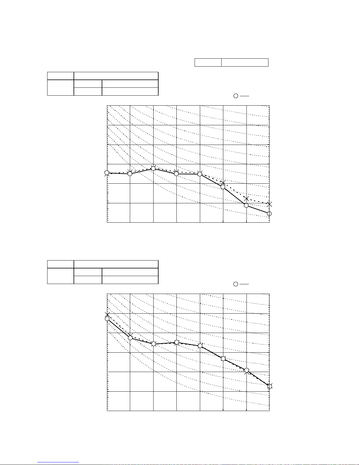
(Indoor Unit)
Model SRK20ZIX-S
Noise
Level
Cooling 39 dB(A)
Heating 38 dB(A)
×
......
Cooling, Heating
1.3 Noise level
Model SRK20ZIX-S
10
20
30
40
50
60
70
63 125 250 500 1000 2000 4000 8000
Mid Octave Band frequency (Hz)
Sound Pressure Level (dB)
(standard 2×10
-5
Pa )
10
20
30
40
50
60
70
N50
N30
N40
N60
N70
N20
(Outdoor Unit)
Model SRC20ZIX-S
Noise
Level
Cooling 47 dB(A)
Heating 47 dB(A)
10
20
30
40
50
60
70
63 125 250 500 1000 2000 4000 8000
Mid Octave Band frequency (Hz)
Sound Pressure Level (dB)
(standard 2×10
-5
Pa )
10
20
30
40
50
60
70
N50
N30
N40
N60
N70
N20
×
......
Cooling, Heating
Condition ISO-T1,JIS C9612
-
8
-
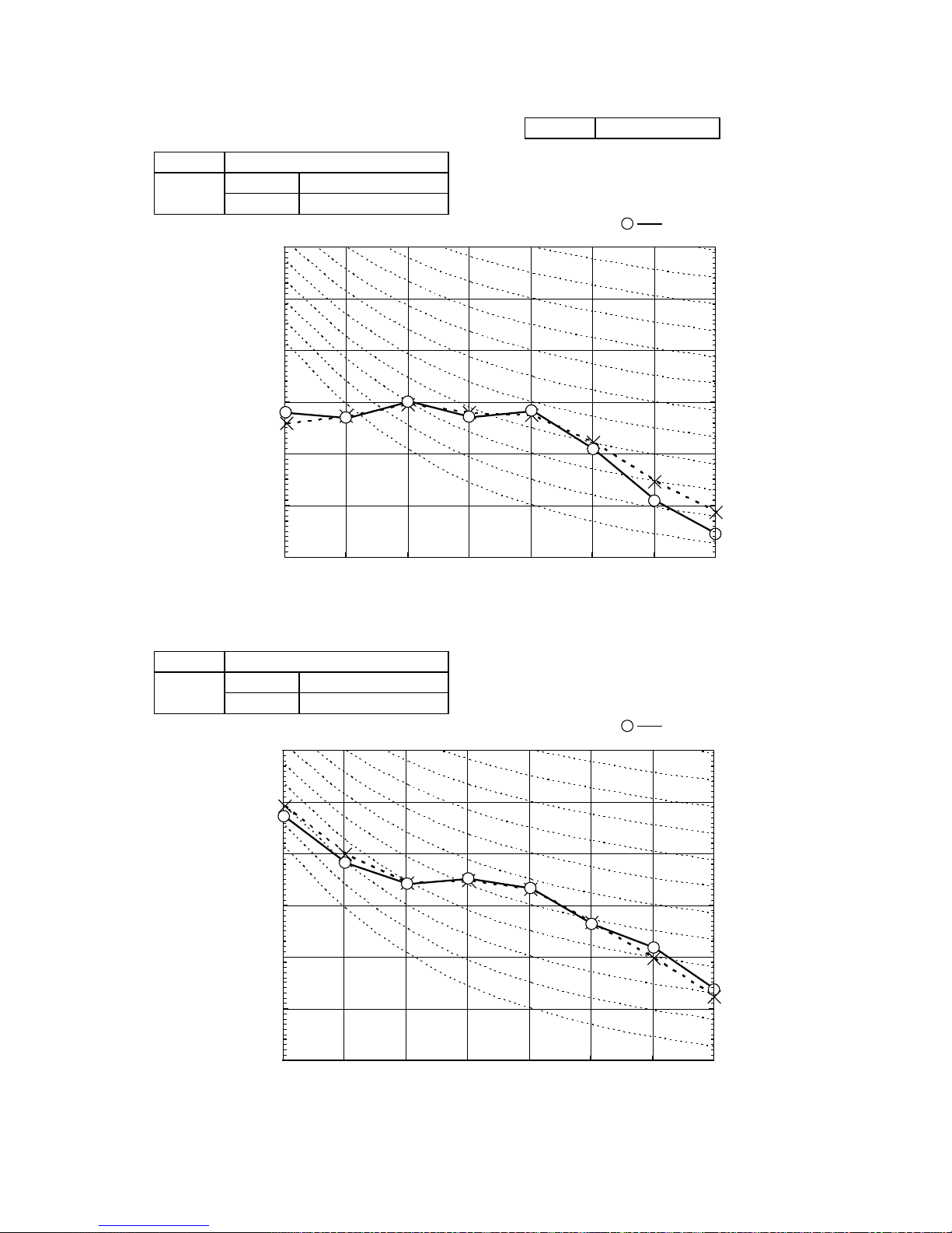
(Indoor Unit)
Model SRK25ZIX-S
Noise
Level
Cooling 41 dB(A)
Heating 41 dB(A)
×
......
Cooling, Heating
Model SRK25ZIX-S
10
20
30
40
50
60
70
63 125 250 500 1000 2000 4000 8000
Mid Octave Band frequency (Hz)
Sound Pressure Level (dB)
(standard 2×10
-5
Pa )
10
20
30
40
50
60
70
N50
N30
N40
N60
N70
N20
(Outdoor Unit)
Model SRC25ZIX-S
Noise
Level
Cooling 47 dB(A)
Heating 47 dB(A)
10
20
30
40
50
60
70
63 125 250 500 1000 2000 4000 8000
Mid Octave Band frequency (Hz)
Sound Pressure Level (dB)
(standard 2×10
-5
Pa )
10
20
30
40
50
60
70
N50
N40
N60
N70
N20
N30
×
......
Cooling, Heating
Condition ISO-T1,JIS C9612
-
9
-
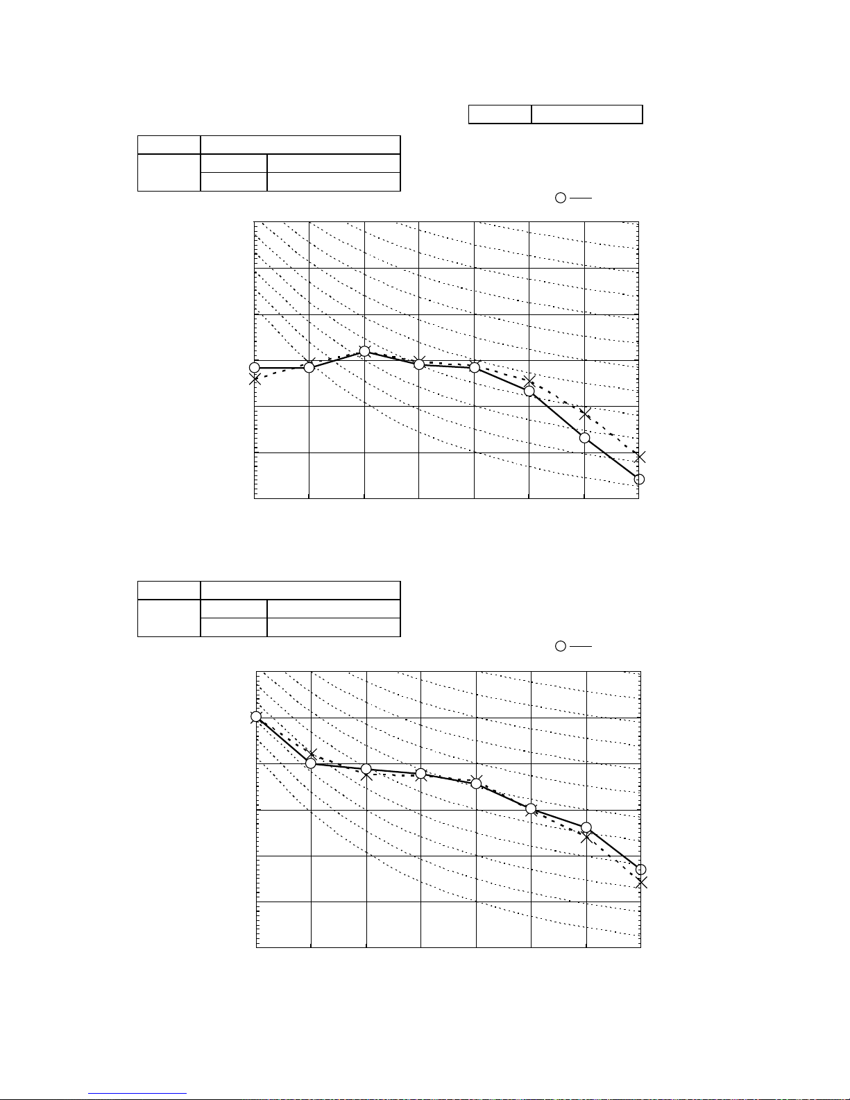
(Indoor Unit)
Model SRK35ZIX-S
Noise
Level
Cooling 43 dB(A)
Heating 42 dB(A)
×
......
Cooling, Heating
Model SRK35ZIX-S
(Outdoor Unit)
Model SRC35ZIX-S
Noise
Level
Cooling 50 dB(A)
Heating 50 dB(A)
×
......
Cooling, Heating
Condition ISO-T1,JIS C9612
10
20
30
40
50
60
70
63 125 250 500 1000 2000 4000 8000
Mid Octave Band frequency (Hz)
Sound Pressure Level (dB)
(standard 2×10
-5
Pa )
10
20
30
40
50
60
70
N50
N30
N40
N60
N70
N20
10
20
30
40
50
60
70
63 125 250 500 1000 2000 4000 8000
Mid Octave Band frequency (Hz)
Sound Pressure Level (dB)
(standard 2×10
-5
Pa )
10
20
30
40
50
60
70
N50
N30
N40
N60
N70
N20

-
10
-
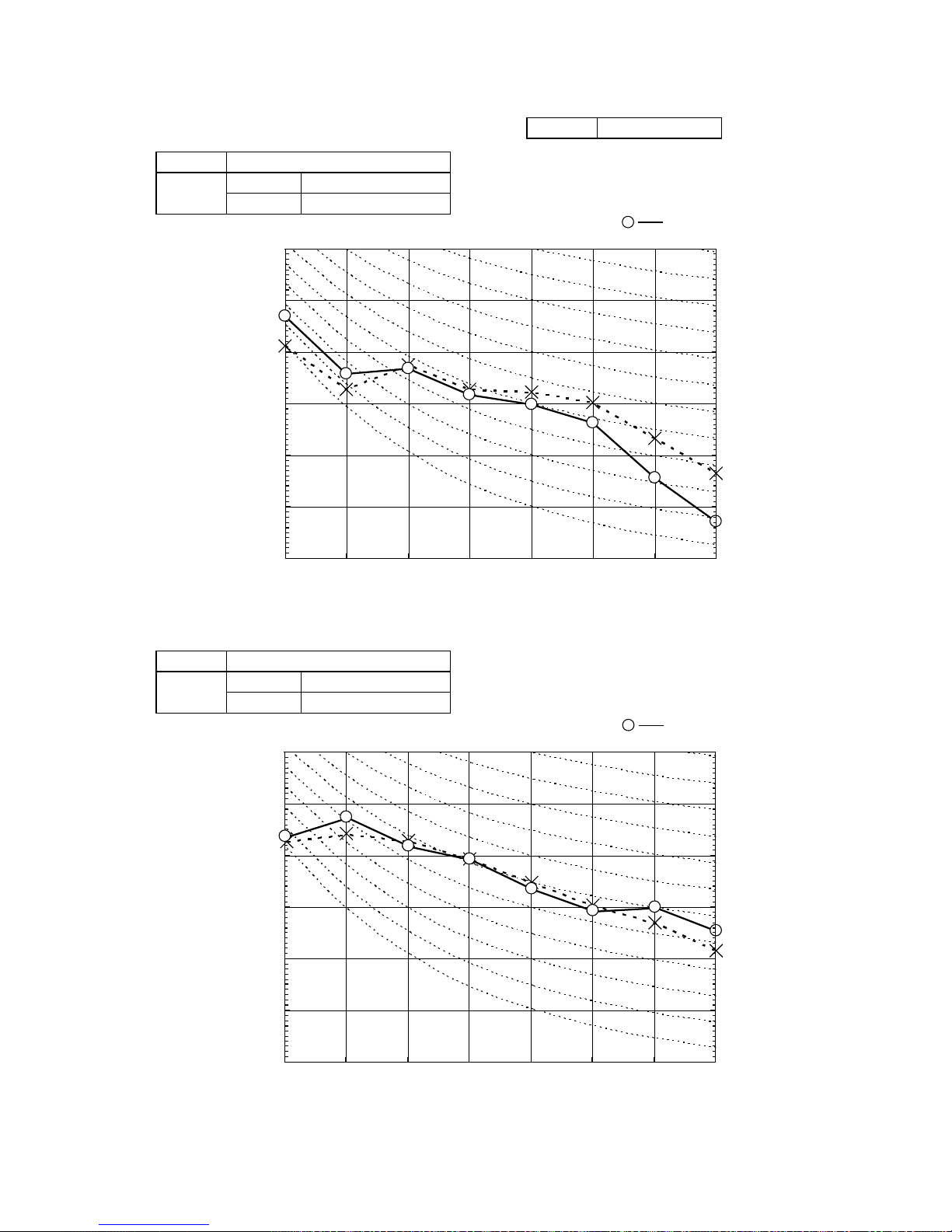
(Indoor Unit)
Model SRK50ZIX-S
Noise
Level
Cooling 45 dB(A)
Heating 45 dB(A)
×
......
Cooling, Heating
Model SRK50ZIX-S
(Outdoor Unit)
Model SRC50ZIX-S
Noise
Level
Cooling 48 dB(A)
Heating 48 dB(A)
×
......
Cooling, Heating
Condition ISO-T1,JIS C9612
10
20
30
40
50
60
70
63 125 250 500 1000 2000 4000 8000
Mid Octave Band frequency (Hz)
Sound Pressure Level (dB)
(standard 2×10
-5
Pa )
10
20
30
40
50
60
70
N50
N30
N40
N60
N70
N20
10
20
30
40
50
60
70
63 125 250 500 1000 2000 4000 8000
Mid Octave Band frequency (Hz)
Sound Pressure Level (dB)
(standard 2×10
-5
Pa )
10
20
30
40
50
60
70
N50
N30
N40
N60
N70
N20
-
11
-
(Indoor Unit)
Model SRK60ZIX-S
Noise
Level
Cooling 47 dB(A)
Heating 45 dB(A)
×
......
Cooling, Heating
Model SRK60ZIX-S
(Outdoor Unit)
Model SRC60ZIX-S
Noise
Level
Cooling 51 dB(A)
Heating 51 dB(A)
×
......
Cooling, Heating
Condition ISO-T1,JIS C9612
10
20
30
40
50
60
70
63 125 250 500 1000 2000 4000 8000
Mid Octave Band frequency (Hz)
Sound Pressure Level (dB)
(standard 2×10
-5
Pa )
10
20
30
40
50
60
70
N50
N30
N40
N60
N70
N20
10
20
30
40
50
60
70
63 125 250 500 1000 2000 4000 8000
Mid Octave Band frequency (Hz)
Sound Pressure Level (dB)
(standard 2×10
-5
Pa )
10
20
30
40
50
60
70
N50
N30
N40
N60
N70
N20
-
12 *
-
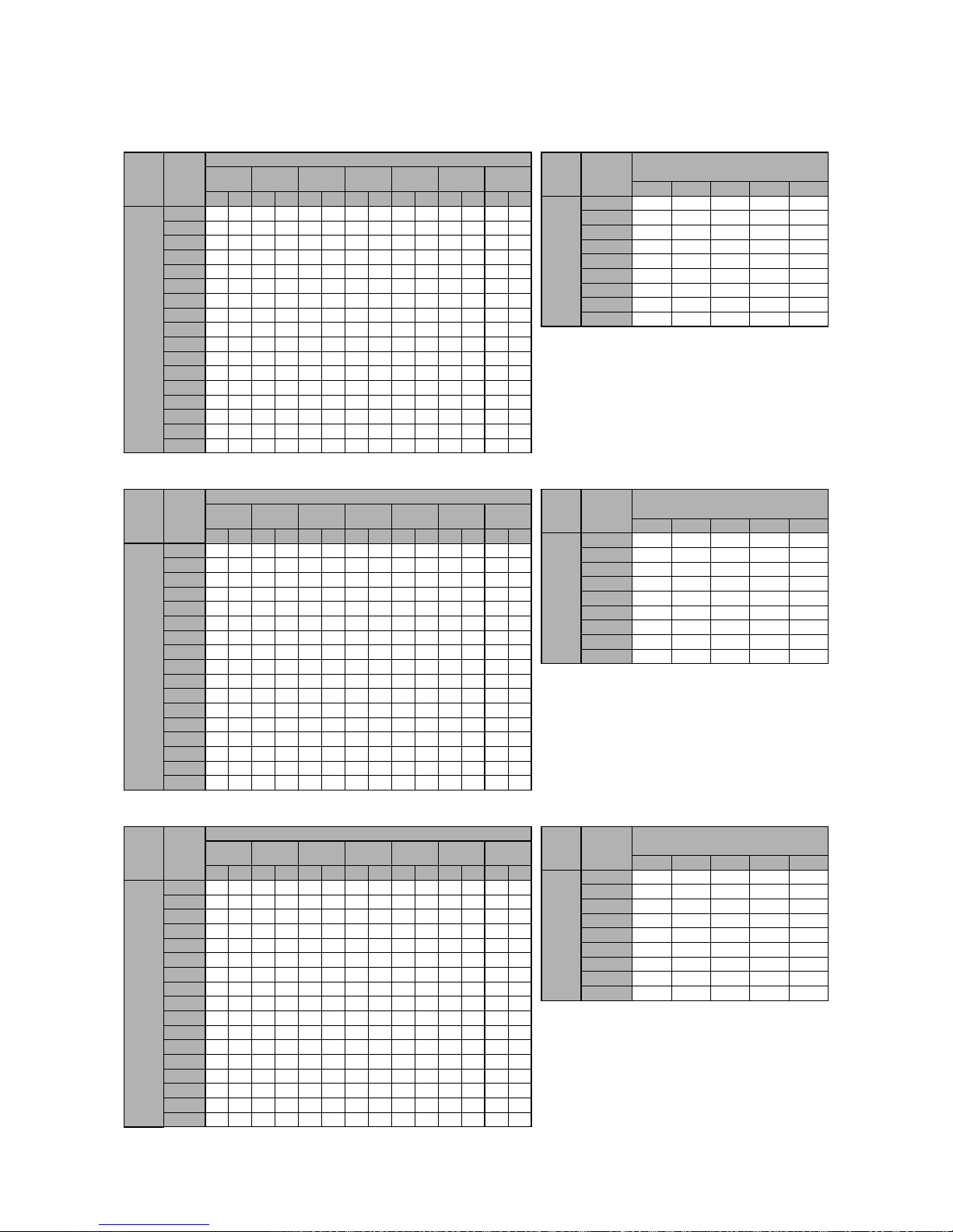
Airf‑ow
Outdoor
airtemp.
Indoorairtemp
21℃DB
14℃WB
23℃DB
16℃WB
26℃DB
18℃WB
27℃DB
19℃WB
28℃DB
20℃WB
31℃DB
22℃WB
33℃DB
24℃WB
TC SHC TC SHC TC SHC TC SHC TC SHC TC SHC TC SHC
Hi
11.5
(m3/min)
10
2.25 2.15 2.36 2.11 2.45 2.24 2.49 2.21 2.53 2.19 2.60 2.30 2.67 2.24
12 2.21 2.12 2.32 2.09 2.41 2.22 2.45 2.20 2.50 2.18 2.58 2.29 2.65 2.24
14 2.17 2.10 2.28 2.07 2.38 2.21 2.42 2.19 2.47 2.17 2.55 2.28 2.62 2.23
16 2.13 2.08 2.24 2.05 2.34 2.19 2.39 2.18 2.43 2.15 2.52 2.27 2.59 2.22
18 2.08 2.06 2.19 2.03 2.30 2.17 2.35 2.16 2.40 2.14 2.49 2.26 2.56 2.21
20 2.04 2.04 2.15 2.02 2.26 2.16 2.31 2.15 2.36 2.13 2.45 2.25 2.53 2.20
22 1.99 1.99 2.10 2.00 2.22 2.15 2.28 2.13 2.32 2.12 2.42 2.23 2.50 2.19
24 1.94 1.94 2.05 1.98 2.18 2.13 2.24 2.11 2.28 2.10 2.38 2.23 2.47 2.18
26 1.90 1.90 2.01 1.97 2.14 2.11 2.20 2.10 2.24 2.08 2.35 2.21 2.43 2.18
28 1.85 1.85 1.96 1.94 2.09 2.09 2.15 2.09 2.20 2.05 2.31 2.20 2.40 2.16
30 1.79 1.79 1.90 1.90 2.05 2.05 2.11 2.05 2.16 2.04 2.27 2.19 2.36 2.15
32 1.74 1.74 1.85 1.85 2.00 2.00 2.07 2.04 2.12 2.02 2.23 2.18 2.32 2.14
34 1.69 1.69 1.80 1.80 1.95 1.95 2.02 2.02 2.07 2.01 2.19 2.16 2.28 2.13
35 1.66 1.66 1.77 1.77 1.93 1.93 2.00 2.00 2.05 2.01 2.17 2.16 2.26 2.12
36 1.63 1.63 1.74 1.74 1.90 1.90 1.98 1.98 2.02 2.00 2.15 2.15 2.24 2.11
38 1.58 1.58 1.68 1.68 1.85 1.85 1.93 1.93 1.98 1.98 2.11 2.11 2.20 2.10
39 1.55 1.55 1.66 1.66 1.83 1.83 1.91 1.91 1.95 1.95 2.08 2.08 2.18 2.10
Air‑fow
outdoor
airtemp.
indoorairtemp
16℃DB 18℃DB 20℃DB 22℃DB 24℃DB
Hi
12.0
(m3/min)
‑15℃WB 1.54 1.51 1.47 1.44 1.41
‑10℃WB 1.74 1.71 1.69 1.64 1.61
‑5℃WB 1.89 1.86 1.82 1.80 1.77
0℃WB 1.98 1.95 1.91 1.89 1.86
5℃WB 2.52 2.49 2.48 2.43 2.39
6℃WB
2.56 2.53 2.50 2.47 2.44
10℃WB 2.72 2.69 2.68 2.64 2.61
15℃WB 2.96 2.93 2.91 2.88 2.85
20℃WB
3.18 3.15 3.14 3.10 3.08
HeatMode
Model SRK20ZIX-S
CoolMode
Air‑fow
Outdoor
airtemp.
Indoorairtemp
21℃DB
14℃WB
23℃DB
16℃WB
26℃DB
18℃WB
27℃DB
19℃WB
28℃DB
20℃WB
31℃DB
22℃WB
33℃DB
24℃WB
TC SHC TC SHC TC SHC TC SHC TC SHC TC SHC TC SHC
Hi
12.5
(m3/min)
10
2.87 2.693.012.653.122.80 3.17 2.77 3.23 2.74 3.32 2.88 3.41 2.81
12
2.82 2.672.962.633.072.78 3.13 2.75 3.19 2.73 3.28 2.86 3.38 2.80
14
2.77 2.642.902.613.032.76 3.09 2.74 3.14 2.69 3.25 2.85 3.34 2.79
16
2.712.612.852.582.982.74 3.04 2.70 3.10 2.68 3.21 2.84 3.31 2.78
18
2.662.592.802.562.932.71 3.00 2.69 3.05 2.66 3.17 2.82 3.27 2.77
20
2.602.562.742.542.882.69 2.95 2.67 3.01 2.65 3.13 2.81 3.23 2.75
22
2.542.542.682.512.832.67 2.90 2.65 2.96 2.63 3.08 2.80 3.19 2.74
24
2.482.482.622.482.782.65 2.85 2.64 2.91 2.61 3.04 2.78 3.15 2.72
26
2.422.422.562.462.722.63 2.80 2.62 2.86 2.60 2.99 2.76 3.10 2.71
28
2.352.35 2.492.432.672.62 2.75 2.60 2.81 2.58 2.95 2.75 3.06 2.70
30
2.292.29 2.432.402.612.59 2.69 2.58 2.75 2.56 2.90 2.74 3.01 2.69
32
2.222.222.362.362.552.55 2.64 2.56 2.70 2.54 2.85 2.71 2.96 2.67
34
2.152.152.292.292.492.49 2.58 2.55 2.64 2.53 2.79 2.70 2.91 2.65
35
2.122.122.262.262.46 2.46 2.55 2.53 2.61 2 .52 2.77 2.69 2.89 2.65
36
2.082.08 2.222.222.43 2.43 2.52 2.52 2.58 2 .51 2.74 2.68 2.86 2.64
38
2.012.012.152.152.36 2.36 2.46 2.46 2.52 2 .49 2.69 2.67 2.81 2.60
39
1.971.972.112.112.33 2.33 2.43 2.43 2.49 2 .48 2.66 2.63 2.78 2.59
Model SRK25ZIX-S
CoolMode
Airf‑ow
outdoor
airtemp.
indoorairtemp
16℃DB 18℃DB 20℃DB 22℃DB 24℃DB
Hi
13.0
(m3/min)
‑15℃WB 1.93 1.88 1.84 1.80 1.76
‑10℃WB 2.18 2.14 2.11 2.06 2.02
‑5℃WB 2.36 2.33 2.28 2.25 2.22
0℃WB 2.47 2.44 2.40 2.37 2.33
5℃WB 3.15 3.12 3.10 3.04 2.99
6℃WB 3.20 3.17 3.13 3.09 3.05
10℃WB 3.40 3.37 3.35 3.30 3.27
15℃WB 3.70 3.67 3.65 3.61 3.57
20℃WB 3.98 3.95 3.93 3.88 3.85
HeatMode
Air‑fow
outdoor
airtemp.
indoorairtemp
16℃DB 18℃DB 20℃DB 22℃DB 24℃DB
Hi
14.0
(m3/min)
‑15℃WB 2.65 2.59 2.53 2.48 2.42
‑10℃WB 2.99 2.94 2.90 2.83 2.77
‑5℃WB 3.24 3.20 3.13 3.10 3.05
0℃WB 3.40 3.35 3.29 3.25 3.20
5℃WB 4.33 4.28 4.26 4.17 4.11
6℃WB 4.40 4.35 4.30 4.25 4.19
10℃WB 4.68 4.63 4.60 4.54 4.49
15℃WB 5.09 5.04 5.01 4.95 4.91
20℃WB 5.47 5.42 5.40 5.34 5.29
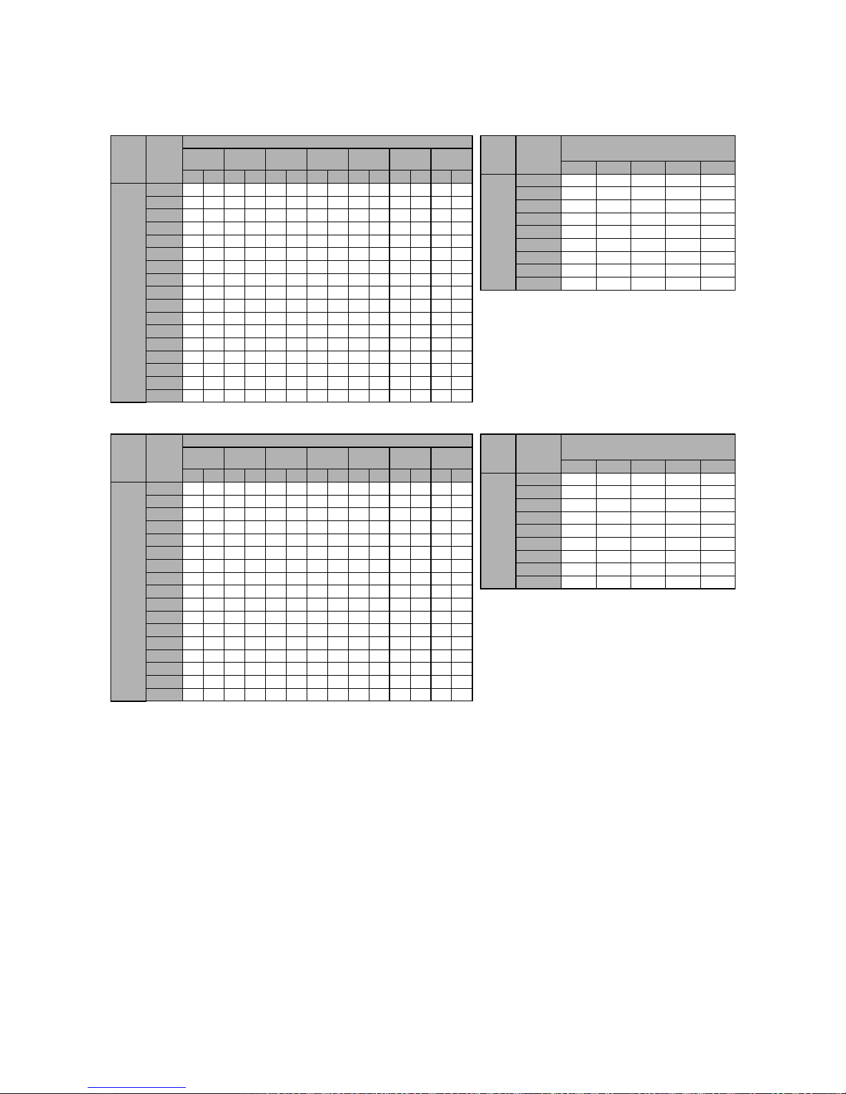
HeatMode
Air‑fow
Outdoor
airtemp.
Indoorairtemp
21℃DB
14℃WB
23℃DB
16℃WB
26℃DB
18℃WB
27℃DB
19℃WB
28℃DB
20℃WB
31℃DB
22℃WB
33℃DB
24℃WB
TC SHC TC SHC TC SHC TC SHC TC SHC TC SHC TC SHC
Hi
13.5
(m3/min)
10
3.94 3.47 4.13 3.42 4.28 3.59 4.35 3.55 4.43 3.51 4.56 3.66 4.68 3.55
12 3.87 3.44 4.06 3.39 4.22 3.56 4.29 3.53 4.37 3.49 4.51 3.65 4.63 3.53
14 3.80 3.40 3.99 3.36 4.16 3.54 4.24 3.50 4.31 3.47 4.46 3.61 4.59 3.52
16 3.72 3.37 3.91 3.32 4.09 3.51 4.18 3.48 4.25 3.44 4.40 3.59 4.54 3.50
18 3.65 3.33 3.84 3.29 4.03 3.48 4.11 3.45 4.19 3.42 4.35 3.57 4.49 3.49
20 3.57 3.30 3.76 3.25 3.96 3.46 4.05 3.43 4.13 3.39 4.29 3.55 4.43 3.47
22 3.49 3.26 3.68 3.22 3.89 3.43 3.98 3.40 4.06 3.37 4.23 3.53 4.38 3.45
24 3.40 3.22 3.59 3.19 3.81 3.40 3.91 3.38 3.99 3.35 4.17 3.51 4.32 3.44
26 3.32 3.18 3.51 3.14 3.74 3.37 3.84 3.35 3.92 3.32 4.11 3.49 4.26 3.42
28 3.23 3.14 3.42 3.11 3.66 3.34 3.77 3.32 3.85 3.30 4.04 3.47 4.20 3.40
30 3.14 3.10 3.33 3.07 3.58 3.31 3.70 3.29 3.78 3.26 3.98 3.45 4.13 3.38
32 3.05 3.05 3.24 3.03 3.50 3.27 3.62 3.26 3.70 3.24 3.91 3.43 4.06 3.36
34 2.95 2.95 3.14 3.00 3.41 3.24 3.54 3.23 3.62 3.21 3.84 3.40 4.00 3.34
35 2.91 2.91 3.10 2.98 3.37 3.23 3.50 3.22 3.58 3.20 3.80 3.39 3.96 3.33
36 2.86 2.86 3.05 2.96 3.33 3.21 3.46 3.20 3.54 3.18 3.76 3.38 3.92 3.32
38 2.76 2.76 2.95 2.91 3.24 3.18 3.38 3.18 3.46 3.15 3.69 3.36 3.85 3.30
39 2.71 2.71 2.90 2.89 3.20 3.16 3.33 3.16 3.42 3.14 3.65 3.34 3.81 3.29
Model SRK35ZIX-S
CoolMode
1.4 Sensible heat capacity
-
13
-
Air flow
Outdoor
air temp.
Indoor air temp
21˚CDB
14˚CWB
23˚CDB
16˚CWB
26˚CDB
18˚CWB
27˚CDB
19˚CWB
28˚CDB
20˚CWB
31˚CDB
22˚CWB
33˚CDB
24˚CWB
TC SHC TC SHC TC SHC TC SHC TC SHC TC SHC TC SHC
Hi
13.5
(m3/min)
10
5.63 4.27 5.90 4.20 6.11 4.32 6.22 4.26 6.32 4.21 6.51 4.30 6.69 4.17
12 5.53 4.22 5.80 4.15 6.03 4.29 6.14 4.23 6.25 4.18 6.44 4.27 6.62 4.15
14 5.43 4.17 5.70 4.10 5.94 4.25 6.05 4.20 6.16 4.14 6.37 4.25 6.55 4.12
16 5.32 4.11 5.59 4.05 5.85 4.21 5.96 4.16 6.08 4.10 6.29 4.22 6.48 4.10
18 5.21 4.05 5.48 3.99 5.75 4.16 5.88 4.12 5.99 4.07 6.21 4.19 6.41 4.08
20 5.10 3.99 5.37 3.94 5.65 4.12 5.78 4.08 5.90 4.03 6.13 4.16 6.33 4.05
22 4.98 3.93 5.25 3.89 5.55 4.07 5.69 4.04 5.80 3.99 6.05 4.13 6.25 4.02
24 4.86 3.87 5.14 3.83 5.45 4.03 5.59 4.00 5.71 3.95 5.96 4.10 6.17 3.99
26 4.74 3.81 5.01 3.77 5.34 3.98 5.49 3.95 5.61 3.91 5.87 4.07 6.08 3.97
28 4.61 3.75 4.89 3.71 5.23 3.93 5.39 3.91 5.50 3.87 5.78 4.03 5.99 3.93
30 4.49 3.68 4.76 3.65 5.11 3.88 5.28 3.86 5.40 3.82 5.68 3.99 5.90 3.90
32 4.35 3.62 4.63 3.59 5.00 3.83 5.17 3.82 5.29 3.78 5.58 3.96 5.81 3.87
34 4.22 3.55 4.49 3.53 4.88 3.78 5.06 3.78 5.18 3.74 5.48 3.92 5.71 3.83
35 4.15 3.52 4.42 3.50 4.82 3.75 5.00 3.75 5.12 3.71 5.43 3.91 5.66 3.82
36 4.08 3.48 4.35 3.45 4.76 3.73 4.94 3.72 5.06 3.69 5.37 3.88 5.61 3.80
38 3.94 3.41 4.21 3.39 4.63 3.67 4.82 3.68 4.94 3.65 5.27 3.85 5.50 3.77
39 3.87 3.38 4.14 3.36 4.57 3.65 4.76 3.65 4.88 3.62 5.21 3.83 5.45 3.75
Model SRK50ZIX-S
Cool Mode
Air flow
outdoor
air temp.
indoor air temp
16˚CDB 18˚CDB 20˚CDB 22˚CDB 24˚CDB
Hi
16.5
(m3/min)
-15˚CWB 3.69 3.61 3.53 3.45 3.38
-10˚CWB 4.18 4.10 4.05 3.95 3.86
-5˚CWB 4.52 4.46 4.37 4.32 4.25
0˚CWB 4.74 4.67 4.59 4.54 4.47
5˚CWB 6.04 5.97 5.94 5.82 5.74
6˚CWB
6.14 6.07 6.00 5.92 5.85
10˚CWB
6.52 6.46 6.42 6.34 6.27
15˚CWB 7.10 7.04 6.99 6.91 6.85
20˚CWB
7.63 7.57 7.53 7.45 7.39
Heat Mode
Air flow
Outdoor
air temp.
Indoor air temp
21˚CDB
14˚CWB
23˚CDB
16˚CWB
26˚CDB
18˚CWB
27˚CDB
19˚CWB
28˚CDB
20˚CWB
31˚CDB
22˚CWB
33˚CDB
24˚CWB
TC SHC TC SHC TC SHC
TC SHC TC SHC TC SHC TC SHC
Hi
14.5
(m3/min)
10
6.76 4.98 7.08 4.90 7.34 5.03
7.46 4.96 7.59 4.88 7.81 4.98 8.02 4.81
12 6.64 4.92 6.96 4.84 7.23 4.98 7.36 4.91 7.49 4.84 7.73 4.94 7.94 4.78
14 6.51 4.84 6.83 4.78 7.13 4.93 7.26 4.87 7.40 4.80 7.64 4.91 7.86 4.75
16 6.38 4.78 6.71 4.70 7.01 4.87
7.16 4.82 7.29 4.75 7.55 4.87 7.78 4.72
18 6.25 4.71 6.58 4.64 6.90 4.82 7.05 4.76 7.19 4.71 7.46 4.83 7.69 4.68
20 6.12 4.64 6.44 4.57 6.78 4.75 6.94 4.71 7.08 4.65 7.36 4.79 7.60 4.65
22 5.98 4.56 6.30 4.51 6.66 4.70 6.83 4.66 6.97 4.60 7.26 4.75 7.50 4.60
24 5.83 4.48 6.16 4.44 6.53 4.65 6.71 4.61 6.85 4.56 7.15 4.72 7.40 4.57
26 5.69 4.41 6.02 4.36 6.41 4.59
6.59 4.56 6.73 4.51 7.04 4.65 7.30 4.53
28 5.54 4.33 5.87 4.29 6.27 4.53 6.46 4.51 6.60 4.46 6.93 4.61 7.19 4.50
30 5.38 4.25 5.71 4.22 6.14 4.47 6.33 4.45 6.48 4.40 6.82 4.57 7.08 4.46
32 5.23 4.18 5.55 4.14 6.00 4.41 6.20 4.39 6.35 4.35 6.70 4.53 6.97 4.42
34 5.06 4.09 5.39 4.06 5.85 4.34 6.07 4.34 6.21 4.29 6.57 4.49 6.85 4.39
35 4.98 4.05 5.31 4.03 5.78 4.31 6.00 4.31 6.14 4.27 6.51 4.47 6.79 4.37
36 4.90 4.01 5.22 3.99 5.71 4.28 5.93 4.28 6.07 4.24 6.45 4.44 6.73 4.34
38 4.73 3.93 5.05 3.91 5.56 4.21
5.79 4.22 5.93 4.18 6.32 4.39 6.60 4.30
39 4.65 3.88 4.97 3.87 5.48 4.18 5.72 4.18 5.86 4.15 6.25 4.37 6.54 4.28
Air flow
outdoor
air temp.
indoor air temp
16˚CDB 18˚CDB 20˚CDB 22˚CDB 24˚CDB
Hi
17.0
(m3/min)
-15˚CWB
4.18 4.09 4.00 3.92 3.83
-10˚CWB 4.73 4.65 4.59 4.47 4.38
-5˚CWB 5.13 5.05 4.95 4.90 4.82
0˚CWB 5.38 5.30 5.20 5.14 5.07
5˚CWB 6.85 6.77 6.73 6.60 6.51
6˚CWB 6.96 6.88 6.80 6.71 6.63
10˚CWB 7.39 7.32 7.28 7.18 7.11
15˚CWB 8.05 7.98 7.92 7.83 7.76
20˚CWB
8.65 8.58 8.54 8.44 8.37
Heat Mode
Model SRK60ZIX-S
Cool Mode

-
14
-
1.5 Application data
1.5.1 Installation of indoor unit
Please read these "Safety Precautions" first then accurately execute the installation work.
For installing qualified personnel, take precautions in respect to themselves by using suitable protective clothing, groves, etc., and then perform the installation works.
Though the precautionary points indicated herein are divided under two headings, and , those points which are related to the strong possibility of an installation done in error resulting in death, serious injury or environmental pollution are listed in the section. However, there is also a possibility of
serious consequences in relationship to the points listed in the section as well. In either case, important safety related information is indicated, so by all means, properly observe all that is mentioned.
Please pay attention not to fall down the tools, etc. when installing the unit at the high position.
After completing the installation, along with confirming that no abnormalities were seen from the operation tests. Please explain operating methods as well as maintenance methods to the user (customer) of this equipment, based on the user's manual. Moreover, ask the customer to keep this sheet together with the user's manual.
If unusual noise can be heard during operation, consult the dealer.
SAFETY PRECAUTIONS
This instruction manual illustrates the method of installing an indoor unit.
For electrical wiring work, please see instructions set out on the backside.
For outdoor unit installation and refrigerant piping, please refer to the installation manual that comes with your outdoor unit.
A wired remote control unit is supplied separately as an optional part.
INSTALLATION DIRECTIONS
WALL MOUNTED TYPE AIR CONDITIONER.
R410A REFRIGERANT USED
RKY012A007
WARNING
Please avoid installing this unit in the locations where oil splashes and moisture are abundant (e.g., kitchens, mechanical workshops) or where the outside
air is likely to flow in. These locations may cause corrosion and lower performance of the heat exchanger and cause damage to plastic parts.
Please avoid installing this unit in the locations with corrosive gases (such as sulfurous acid gas), inflammable gases (such as thinner, gasoline) and areas
where there are possibilities of gas accumulation or where a volatile inflammable material is handled. These locations can cause corrosion to the heat
exchanger and damage to plastic parts. Also, the inflammable gas could cause fire.
Please avoid installing this unit in the vicinity of equipment generating electromagnetic waves such as hospital equipment or equipment generating
high-frequency waves. A failure to observe this instruction may result in controller performance errors due to noise generation.
Please avoid installing and using this unit in a place where it is subject to sea breezes (coastal area). Installation in such a place may result in the corrosion
of exterior panels and the heat exchanger.
Do not place the remote control at locations that receives direct sunlight. This may cause malfunction and deformation.
Spatters from welding, etc., if hit the unit, can damage (pinhole) its drain pan and other components and cause a water leak. Care must be taken in
performing a welding operation near this unit and take necessary precautions to prevent spatters from entering this unit.
For installation work, be careful not to get injured with the heat exchanger, piping flare portion or screws etc.
For the drain pipe, follow the installation manual to insure that it allows proper drainage and thermally insulate it to prevent condensation. Inadequate
plumbing can result in water leakage and water damage to interior items.
The installation of an earth leakage breaker is necessary depending on the established location of the unit. Not installing an earth leakage breaker may
result in electric shock.
When perform the air conditioner operation (cooling or drying operation) in which ventilator is installed in the room. In this case, using the air conditioner in
parallel with the ventilator, there is the possibility that drain water may backflow in accordance with the room lapse into the negative pressure status.
Therefore, set up the opening port such as incorporate the air into the room that may appropriate to ventilation (For example; Open the door a little). In
addition, just as above, so set up the opening port if the room lapse into negative pressure status due to register of the wind for the high rise apartment etc.
Secure the regulated space for inspection and maintenance
When it is not possible to keep enough space, this may cause injury due to falling from the installation place.
To prevent the falling, institute the everlasting ladder and handrail etc., to the aisle when installing the outdoor unit in the location with rooftop or altitude.
Or, for surrounding of the outdoor unit, institute the fence and handrail etc., to the aisle to prevent the falling.
Performing the heat insulation and condensation of the refrigerant piping
If the heat insulation and condensation of the refrigerant piping is not correctly, this m ay cause the water leakage, dew dropping and household wetting etc.
Be careful not to injury due to damage of the unit installing work when leaving of the packaging materials.
Do not install the unit where there is a concern about leakage of combustible gas.
The rare event of leaked gas collecting around the unit could result in an outbreak of fire.
Do not touch the suction or aluminum fin on the outdoor unit
This may cause injury.
Do not install the outdoor unit where is likely to be a nest for small animals
Small animals may come into the electronic components and may cause breakdown and fire. Also,instruct the user to keep the surroundings clean.
Do not install the outdoor unit at the place where fan airflow falls on the garden tree etc.
This may cause damage to the garden tree etc., due to the fan airflow.
Do not put anything on the outdoor unit and operating the unit.
This may cause damage the objects or injury due to falling to the object.
Symbols which appear frequently in the text have the following meaning
Strictly prohibited
Observe instructions with
great care
Provide proper earthing
CAUTION
CAUTIONS FOR INSTALLATION
The system should be applied to places as households, residences and the like.
The equipment shall be installed in accordance with national wiring regulations.
The connection to the fixed wiring of the mains supply must be made via a double pole isolating switch with a contact gap of at least 3mm in each pole.
When the outdoor unit has a possibility of being overturned or being displaced and fall from its original installation position, the outdoor unit should be
fixed in its position by use of anchor bolts or wires.
CAUTION
CAUTION
WARNING
WARNING
To disconnect the appliance from the mains supply this appliance must be connected to the mains by means of a circuit breaker or a switch (use a
recognized 16A) with a contact separation of at least 3mm.
The appliance shall be installed in accordance with national wiring regulations.
When a plug is connected to the power cord, a plug conforming to the IEC60884-1 standard must be used.
This system should be applied to places as households, residences and the like. Application to inferior environment such as engineering shop could
cause equipment malfunction.
Please entrust installation to either the company which sold you the equipment or to a professional contractor. Defects from improper installations can be
the cause of water leakage, electric shocks and fires.
Execute the installation accurately, based on following the installation manual. Again, improper installations can result in water leakage, electric shocks
and fires.
For installation, confirm that the installation site can sufficiently support heavy weight. When strength is insufficient, injury can result from a falling of the
unit.
For electrical work, please see that a licensed electrician executes the work while following the safety standards related to electrical equipment, and local
regulations as well as the installation instructions, and that only exclusive use circuits are used.
Insufficient power source circuit capacity and defective installment execution can be the cause of electric shocks and fires.
Accurately connect wiring using the proper cable, and insure that the external force of the cable is not conducted to the terminal connection part, through
properly securing it. Improper connection or securing can result in heat generation or fire.
Take care that wiring does not rise upward, and accurately install the lid/service panel. It's improper installation can also result in heat generation or fire.
Always use accessory parts and authorized parts for installation construction. Using parts not authorized by this company can result in water leakage,
electric shock, fire and refrigerant leakage.
Ventilate the work area when refrigerant leaks during the operation.
Coming in contact with fire, refrigerant could generate toxic gas.
Confirm after the foundation construction work that refrigerant does not leak.
If coming in contact with fire of a fan heater, a stove or a movable cooking stove, etc., refrigerant leaking in the room could generate toxic gas.
Turn off the power source during working on the inside of the unit such as servicing or installing work.
This may cause electric shock.
Use only pipe, flare nut and tools that have been designed to operate with R410A.
Using existing parts (R22) may cause the unit failure, even as due to serious accident such as explosion of the cooling cycle or injury etc.
For pump down work, stop the compressor before removing the refrigerant pipe.
If the refrigerant pipe is removed when the compressor is in operation with the service valves open (liquid side and gas side), air would be mixed in the
refrigerant circuit and this may cause explosion and injuries due to abnormal high pressure in the cooling cycle.
Connect the pipes for refrigerant circuit securely in installation work before compressor is operated
If the compressor is operated when the service valve is open without connecting the pipe, this may cause frostbite and injuries due to refrigerant leakage
rapidly. Also, the unit is absorbed the air etc., this may cause explosion and injuries due to abnormal high pressure in the cooling cycle.
Tighten the flare nut by torque wrench with specified method.
If the flare nut were tightened with excess torque, this may cause burst and refrigerant leakage after a long period, and then, this may cause generate the
harmful substance due to touch the flammable materials.
Make sure there is no dust or clogging on both plug and socket nor loose connection of the socket before plugging of the power plug. Then, the power
plug must be inserted tightly.
Accumulation of dust, clogging on the socket or plug, or loose installation of the socket may cause electric shock and fire. Replace the socket if it is loose.
Do not open the service valves (liquid side and gas side) until refrigerant piping construction, air-tightness test and evacuation are completed
This may cause frostbite and injuries due to refrigerant leakage rapidly. Also, if the refrigerant gas leakage occurs during installing work, stop the work
such as brazing work and then ventilation of the room. This may cause generate the toxic gas due to touch the flammable materials.
Do not put the drain pipe directly into the ditch where toxic gas such as sulfur is generated.
Toxic gas would flow into the room. Also, this may cause corrosion of indoor unit, and malfunction or refrigerant leakage.
Be sure to bring back the packing material, form polystyrene, band and vinyl back etc., of the indoor and/or outdoor units after complete the installation
work, and then implement appropriate measures such as breaking them.
When setting up or moving the location of the air conditioner, do not mix air etc. or anything other than the designated refrigerant (R410A) within the
refrigeration cycle.
Rupture and injury caused by abnormal high pressure can result from such mixing.
Do not processing, splice the power cord, or share a socket with other power plugs.
This may cause fire or electric shock due to defecting contact, defecting insulation and over-current etc.
Do not bundling, winding or processing for the power cord. Or, do not deforming the power plug due to tread it
This may cause fire or heating.
Do not vent R410A into the atomosphere:R410A is a fluor inated greenhouse gas. covered by the Kyoto Protocol with a Groval Warming Potential (GWP)
=1975
Execute proper grounding. Do not connect the ground wire to a gas pipe, water pipe, lightning rod or a telephone ground wire. Improper placement of
ground wires can result in electric shock.
-
15
-
Please read these "Safety Precautions" first then accurately execute the installation work.
For installing qualified personnel, take precautions in respect to themselves by using suitable protective clothing, groves, etc., and then perform the installation works.
Though the precautionary points indicated herein are divided under two headings, and , those points which are related to the strong possibility of an installation done in error resulting in death, serious injury or environmental pollution are listed in the section. However, there is also a possibility of
serious consequences in relationship to the points listed in the section as well. In either case, important safety related information is indicated, so by all means, properly observe all that is mentioned.
Please pay attention not to fall down the tools, etc. when installing the unit at the high position.
After completing the installation, along with confirming that no abnormalities were seen from the operation tests. Please explain operating methods as well as maintenance methods to the user (customer) of this equipment, based on the user's manual. Moreover, ask the customer to keep this sheet together with the user's manual.
If unusual noise can be heard during operation, consult the dealer.
SAFETY PRECAUTIONS
This instruction manual illustrates the method of installing an indoor unit.
For electrical wiring work, please see instructions set out on the backside.
For outdoor unit installation and refrigerant piping, please refer to the installation manual that comes with your outdoor unit.
A wired remote control unit is supplied separately as an optional part.
INSTALLATION DIRECTIONS
WALL MOUNTED TYPE AIR CONDITIONER.
R410A REFRIGERANT USED
RKY012A007
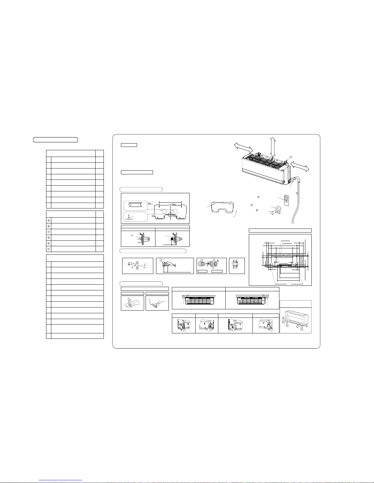
Necessary tools for the installation work
1
2
3
4
5
6
7
8
9
10
11
12
13
①
②
③
④
⑤
⑥
⑦
⑧
⑨
1
1
1
4
2
2
2
2
1
1
1
1
1
1
1
Q'ty
Q'ty
Standard accessories (Installation kit)
Accessories for indoor unit
Installation board
(Attached to the rear of the indoor unit)
Wireless remote control
Remote control holder
Battery [R03(AAA,Micro) 1.5V]
Air-cleaning filters
Filter holders
(Attached to the front panel of indoor unit)
Insulation (#486 50 x 100 t3)
Tapping screws
(for installation board 4dia. by 25mm)
Wood screw
(for remote control switch holder 3.5(mm). by 16mm)
Option parts
Sealing plate
Sleeve
Inclination plate
Putty
Drain hose (extention hose)
Piping cover
(for insulation of connection piping)
Plus headed driver
Knife
Saw
Tape measure
Hammer
Spanner wrench
Torque wrench
Hole core drill (65mm in diameter)
Wrench key (Hexagon) [4m/m]
Flaring tool set
Gas leak detector
Pipe bender
Gauge for projection adjustment
Used when flare is made by using
conventional flare tool
( )
( )
( )
14.0 ~ 61.0N•m
(1.4 ~ 6.1kgf•m)
(
Designed specifically
for R410A
Designed specifically
for R410A
)
Piping in the left direction
Piping in the right rear directionPiping in the left rear direction
Piping in the right direction
INSTALLATION SPACE (INDOOR UNIT)
(FRONT VIEW)
50
Space for
service
Space for
service
120
220
650
450 220
100
120
35
35
58
54
520.8
491.1
559.1
49222.5
48
65 Space for service
15
Space for service
7.7295.75.6
48
Indoor unit
Installation board
Drain hose (ø16)
Piping for Gas
Piping for Liquid
Piping hole (ø65) Piping hole (ø65)
Standard hole
Piping is possible in the rear, left,
left rear, left downward, right or
downward direction.
Right
Rear
Downward
Left rear
Left downward
Left
Installation board
5 cm minimum
from the wall
10 cm minimum
from the wall
6.5 cm minimum from the ceiling
Wireless remote control
Remote control holder
Wood screws
Sleeve
(sold separately)
WARNING
Please avoid installing this unit in the locations where oil splashes and moisture are abundant (e.g., kitchens, mechanical workshops) or where the outside
air is likely to flow in. These locations may cause corrosion and lower performance of the heat exchanger and cause damage to plastic parts.
Please avoid installing this unit in the locations with corrosive gases (such as sulfurous acid gas), inflammable gases (such as thinner, gasoline) and areas
where there are possibilities of gas accumulation or where a volatile inflammable material is handled. These locations can cause corrosion to the heat
exchanger and damage to plastic parts. Also, the inflammable gas could cause fire.
Please avoid installing this unit in the vicinity of equipment generating electromagnetic waves such as hospital equipment or equipment generating
high-frequency waves. A failure to observe this instruction may result in controller performance errors due to noise generation.
Please avoid installing and using this unit in a place where it is subject to sea breezes (coastal area). Installation in such a place may result in the corrosion
of exterior panels and the heat exchanger.
Do not place the remote control at locations that receives direct sunlight. This may cause malfunction and deformation.
Spatters from welding, etc., if hit the unit, can damage (pinhole) its drain pan and other components and cause a water leak. Care must be taken in
performing a welding operation near this unit and take necessary precautions to prevent spatters from entering this unit.
For installation work, be careful not to get injured with the heat exchanger, piping flare portion or screws etc.
For the drain pipe, follow the installation manual to insure that it allows proper drainage and thermally insulate it to prevent condensation. Inadequate
plumbing can result in water leakage and water damage to interior items.
The installation of an earth leakage breaker is necessary depending on the established location of the unit. Not installing an earth leakage breaker may
result in electric shock.
When perform the air conditioner operation (cooling or drying operation) in which ventilator is installed in the room. In this case, using the air conditioner in
parallel with the ventilator, there is the possibility that drain water may backflow in accordance with the room lapse into the negative pressure status.
Therefore, set up the opening port such as incorporate the air into the room that may appropriate to ventilation (For example; Open the door a little). In
addition, just as above, so set up the opening port if the room lapse into negative pressure status due to register of the wind for the high rise apartment etc.
Secure the regulated space for inspection and maintenance
When it is not possible to keep enough space, this may cause injury due to falling from the installation place.
To prevent the falling, institute the everlasting ladder and handrail etc., to the aisle when installing the outdoor unit in the location with rooftop or altitude.
Or, for surrounding of the outdoor unit, institute the fence and handrail etc., to the aisle to prevent the falling.
Performing the heat insulation and condensation of the refrigerant piping
If the heat insulation and condensation of the refrigerant piping is not correctly, this may caus e the water leakage, dew dropping and household wetting etc.
Be careful not to injury due to damage of the unit installing work when leaving of the packaging materials.
Do not install the unit where there is a concern about leakage of combustible gas.
The rare event of leaked gas collecting around the unit could result in an outbreak of fire.
Do not touch the suction or aluminum fin on the outdoor unit
This may cause injury.
Do not install the outdoor unit where is likely to be a nest for small animals
Small animals may come into the electronic components and may cause breakdown and fire. Also,instruct the user to keep the surroundings clean.
Do not install the outdoor unit at the place where fan airflow falls on the garden tree etc.
This may cause damage to the garden tree etc., due to the fan airflow.
Do not put anything on the outdoor unit and operating the unit.
This may cause damage the objects or injury due to falling to the object.
Symbols which appear frequently in the text have the following meaning
Strictly prohibited
Observe instructions with
great care
Provide proper earthing
CAUTION
CAUTIONS FOR INSTALLATION
The system should be applied to places as households, residences and the like.
The equipment shall be installed in accordance with national wiring regulations.
The connection to the fixed wiring of the mains supply must be made via a double pole isolating switch with a contact gap of at least 3mm in each pole.
When the outdoor unit has a possibility of being overturned or being displaced and fall from its original installation position, the outdoor unit should be
fixed in its position by use of anchor bolts or wires.
BEFORE INSTALLATION
Before installation check that the power supply matches the air conditioner.
SELECTION OF INSTALLATION LOCATION
INSTALLATION OF INDOOR UNIT
Indoor unit
Relation between setting plate and indoor unit
Installing the support of piping
(Install at location that meets the following conditions, after getting approval from the customer)
Where there is no obstructions to the air flow and where the cooled and heated air can be evenly distributed.
A solid place where the unit or the wall will not vibrate.
A place where there will be enough space for servicing. (Where space mentioned below can be secured)
Where wiring and the piping work will be easy to conduct.
The place where receiving part is not exposed to the direct rays of the sun or the strong rays of the street lighting.
A place where it can be easily drained.
A place separated at least 1m away from the television or the radio. (To prevent interference to images and sounds.)
Places where this unit is not affected by the high frequency equipment or electric equipment.
Avoid installing this unit in place where there is much oil mist.
Places where there is no electric equipment or household under the installing unit.
Wireless remote control
In case of piping in the right rear direction
A place where the air conditioner can be received the signal surely during operating the wireless remote control.
Places where there is no affected by the TV and radio etc.
Do not place where exposed to direct sunlight or near heat devices such as a stove.
Hold the bottom of the
piping and fix direction
before stretching it and
shaping it.
Drill a hole with whole core drill. In case of rear piping draw out, cut off the lower
and the right side portions of the sleeve collar.
Tape only the portion
that goes through the
wall.
Always tape the wiring
with the piping.
[Top view]
When drilling the wall that contains a metal lath, wire lath or metal plate, be sure to use pipe hole sleeve sold separately.
Matters of special notice when piping from left or central/rear of tha unit.
[Drain hose changing procedures]
Remove the screw and
drain hose, making it
rotate.
Remove it with hand or
pilers.
Insert the drain cap which was removed
at procedure “2” securely using a
hexagonal wrench etc.
Note: Be careful that If it is not Inserted
securely, water leakage may
occur.
Insert the drain hose securely,
making rotate. And install the
screw.
Note: Be careful that If it is not
Inserted securely, water
leakage may occur.
Left-hand-side piping Right-hand-side piping
1. Remove the drain hose.
2. Remove the drain cap.
3. Insert the drain cap. 4. Connect the drain hose.
Installation of Installation board
Drilling of holes and fixture of sleeve (Option parts)
Look for the inside wall structures (Intersediats support or pillar and finally
install the unit after level surface has been checked.)
450
Level position (2 locations)
Mating mark for
level surface
Fixing on concrete wall
Use of nut anchor Use of bolt anchor
Shaping of pipings Taping of the exterior
Pipings
Drain hose
Top
Indoor side
Outdoor side
Nut
(M6)
Mounting
board
Mounting
board
Max.10
Thicknese of the wall + 1.5cm
5
65
Indoor side Outdoor side Installed state
Turn to
tighten
b
b
c
a
Bolt
(M6 12)
Piping for Liquid (20 to 60 type) : ø6.35
Piping for Gas (20 to 35 type) : ø9.52
(50 to 60 type) : ø12.7
Adjustment of the installation board in the horizontal
direction is to be conducted with four screws in a temporary
tightened state.
Adjust so the board will be level by turning the board with
the standard hole as the center.
CAUTION
CAUTION
WARNING
WARNING
To disconnect the appliance from the mains supply this appliance must be connected to the mains by means of a circuit breaker or a switch (use a
recognized 16A) with a contact separation of at least 3mm.
The appliance shall be installed in accordance with national wiring regulations.
When a plug is connected to the power cord, a plug conforming to the IEC60884-1 standard must be used.
This system should be applied to places as households, residences and the like. Application to inferior environment such as engineering shop could
cause equipment malfunction.
Please entrust installation to either the company which sold you the equipment or to a professional contractor. Defects from improper installations can be
the cause of water leakage, electric shocks and fires.
Execute the installation accurately, based on following the installation manual. Again, improper installations can result in water leakage, electric shocks
and fires.
For installation, confirm that the installation site can sufficiently support heavy weight. When strength is insufficient, injury can result from a falling of the
unit.
For electrical work, please see that a licensed electrician executes the work while following the safety standards related to electrical equipment, and local
regulations as well as the installation instructions, and that only exclusive use circuits are used.
Insufficient power source circuit capacity and defective installment execution can be the cause of electric shocks and fires.
Accurately connect wiring using the proper cable, and insure that the external force of the cable is not conducted to the terminal connection part, through
properly securing it. Improper connection or securing can result in heat generation or fire.
Take care that wiring does not rise upward, and accurately install the lid/service panel. It's improper installation can also result in heat generation or fire.
Always use accessory parts and authorized parts for installation construction. Using parts not authorized by this company can result in water leakage,
electric shock, fire and refrigerant leakage.
Ventilate the work area when refrigerant leaks during the operation.
Coming in contact with fire, refrigerant could generate toxic gas.
Confirm after the foundation construction work that refrigerant does not leak.
If coming in contact with fire of a fan heater, a stove or a movable cooking stove, etc., refrigerant leaking in the room could generate toxic gas.
Turn off the power source during working on the inside of the unit such as servicing or installing work.
This may cause electric shock.
Use only pipe, flare nut and tools that have been designed to operate with R410A.
Using existing parts (R22) may cause the unit failure, even as due to serious accident such as explosion of the cooling cycle or injury etc.
For pump down work, stop the compressor before removing the refrigerant pipe.
If the refrigerant pipe is removed when the compressor is in operation with the service valves open (liquid side and gas side), air would be mixed in the
refrigerant circuit and this may cause explosion and injuries due to abnormal high pressure in the cooling cycle.
Connect the pipes for refrigerant circuit securely in installation work before compressor is operated
If the compressor is operated when the service valve is open without connecting the pipe, this may cause frostbite and injuries due to refrigerant leakage
rapidly. Also, the unit is absorbed the air etc., this may cause explosion and injuries due to abnormal high pressure in the cooling cycle.
Tighten the flare nut by torque wrench with specified method.
If the flare nut were tightened with excess torque, this may cause burst and refrigerant leakage after a long period, and then, this may cause generate the
harmful substance due to touch the flammable materials.
Make sure there is no dust or clogging on both plug and socket nor loose connection of the socket before plugging of the power plug. Then, the power
plug must be inserted tightly.
Accumulation of dust, clogging on the socket or plug, or loose installation of the socket may cause electric shock and fire. Replace the socket if it is loose.
Do not open the service valves (liquid side and gas side) until refrigerant piping construction, air-tightness test and evacuation are completed
This may cause frostbite and injuries due to refrigerant leakage rapidly. Also, if the refrigerant gas leakage occurs during installing work, stop the work
such as brazing work and then ventilation of the room. This may cause generate the toxic gas due to touch the flammable materials.
Do not put the drain pipe directly into the ditch where toxic gas such as sulfur is generated.
Toxic gas would flow into the room. Also, this may cause corrosion of indoor unit, and malfunction or refrigerant leakage.
Be sure to bring back the packing material, form polystyrene, band and vinyl back etc., of the indoor and/or outdoor units after complete the installation
work, and then implement appropriate measures such as breaking them.
When setting up or moving the location of the air conditioner, do not mix air etc. or anything other than the designated refrigerant (R410A) within the
refrigeration cycle.
Rupture and injury caused by abnormal high pressure can result from such mixing.
Do not processing, splice the power cord, or share a socket with other power plugs.
This may cause fire or electric shock due to defecting contact, defecting insulation and over-current etc.
Do not bundling, winding or processing for the power cord. Or, do not deforming the power plug due to tread it
This may cause fire or heating.
Do not vent R410A into the atomosphere:R410A is a fluor inated greenhouse gas. covered by the Kyoto Protocol with a Groval Warming Potential (GWP)
=1975
Execute proper grounding. Do not connect the ground wire to a gas pipe, water pipe, lightning rod or a telephone ground wire. Improper placement of
ground wires can result in electric shock.
-
16
-
RKY012A007
Keep the openings of the pipes covered with tapes etc. to prevent dust, sand, etc. from entering them.
2
1
Indoor unit
Latch
(2 locations)
Installation
borad
Installation borad
Wall
Indoor unit base lower latch
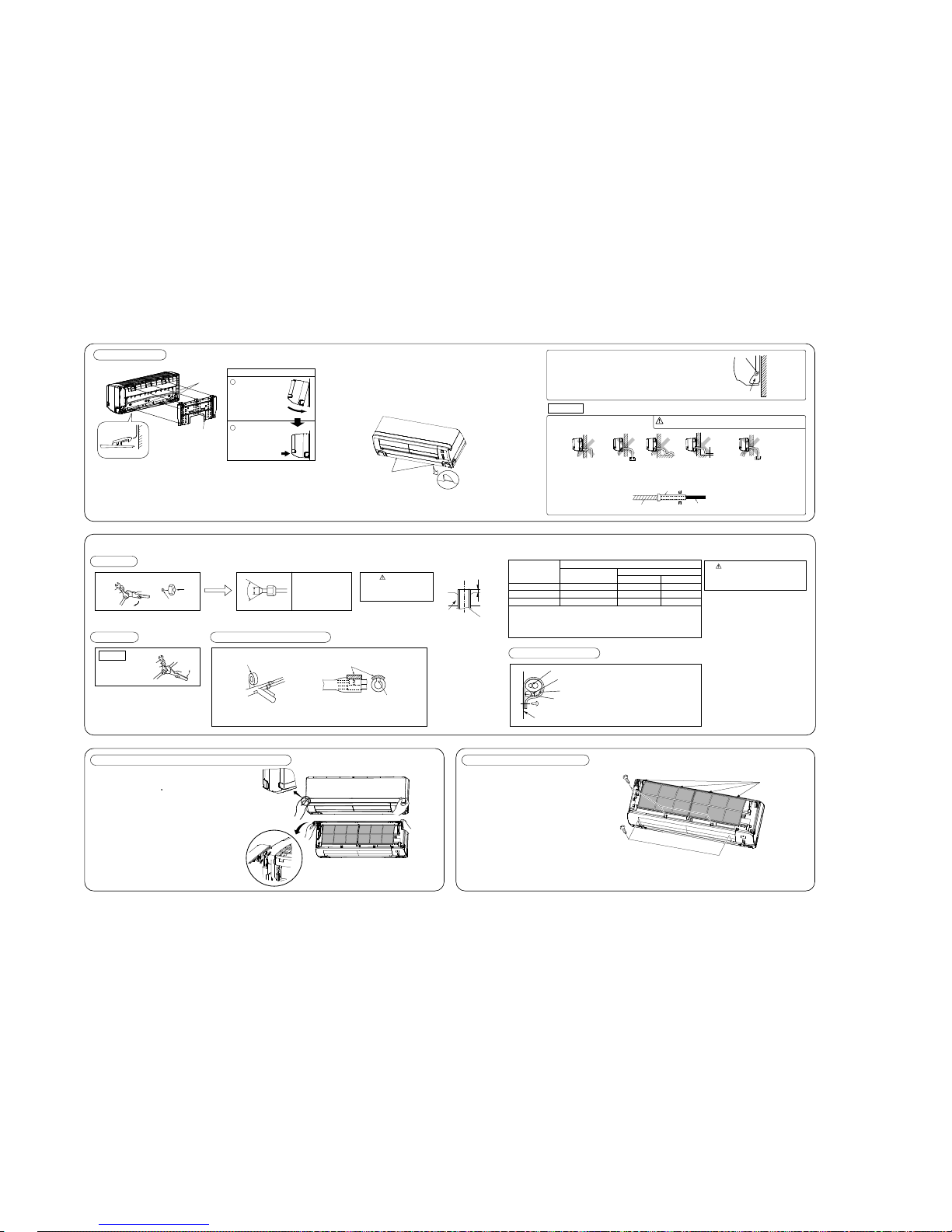
Installation Steps
Pass the pipe through
the hole in the wall,
and hook the upper
part of the indoor unit
to the installation board.
Gently push the lower
part to secure the unit.
① Push up at the marked portion of the indoor unit base lower latch, and slightly pull it
toward you. (both right and left hand sides) (The indoor unit base lower latch can be
removed from the installation board)
② Push up the indoor unit upward. So the indoor unit will be removed from the installation
board.
The marked portion of the indoor
unit base lower latch.
CAUTION
Wall
Gutter
Pipe accommodating section
CONNECTION OF REFRIGERANT PIPINGS
Preparation
Indoor
(Do not turn)
Press
Remove
A
90 ± 0.5°
Dimension A
Liquid side ø6.35 : 9.1 (mm)
Gas side ø9.52 : 13.2 (mm)
ø12.7 : 16.6 (mm)
Remove the flared nuts. (on both liquid and gas sides) Install the removed flared nuts to the pipes to be connected,
then flared the pipes.
Flaring work
CAUTION
Do not apply refrigerating machine
oil to the flared surface.
Measurement B
Flaring
block
Copper pipe
Copper pipe diameter
Use a flare tool designed for R410A or a conventional flare tool.
Please note that measurement B (protrusion from the flaring block) will vary depending on the
type of a flare tool in use.
If a coventional flare tool is used, please use a copper pipe gauge or a similar instrument to
check protrusion so that you can keep measurement B to a correct value.
Clutch type flare tool for
R410A
Conventional (R22) flare tool
ø6.35
ø9.52
ø12.7
0.0 - 0.5
0.0 - 0.5
0.0 - 0.5
1.0 - 1.5
1.0 - 1.5
1.0 - 1.5
1.5 - 2.0
1.5 - 2.0
2.0 - 2.5
Measurement B (mm)
Clutch type Wing nut type
CAUTION
Do not apply excess torque to the flared nuts.
Otherwise, the flared nuts may checkdepending.
Connection
How to remove and fit the front panel
Insulation of the connection portion
Finishing work and fixing
Indoor
Liquid side
Gas side
(Do not turn)
Cover the coupling with insulator and then cover it with tapes.
Cover the indoor unit’s flare-connected joints, after they are checked for a gas leak, with an indoor
unit heat insulating material and then wrap them with a tape with an attached insulation pad placed
over the heat insulating material’s slit area.
Vinyl tape
Use an attached insulation pad for heat insulation.
Position it so that the slit area faces upward.
Connect the pipes on both liquid and gas sides.
Tighten the nuts to the following torque.
Liquid side (ø6.35) : 14.0 - 18.0 N·m (1.4 - 1.8 kgf·m)
Gas side (ø9.52) : 34.0 - 42.0 N·m (3.4 - 4.2 kgf·m)
(ø12.7) : 49.0 - 61.0 N·m (4.9 - 6.1 kgf·m)
Connection wiring,
Earth wiring
Outer tape
Refrigerant piping
Drain hose
Wood screw
Clamp
Cover the exterior portion with outer tape and
shape the piping so it will match the contours
of the route that the piping to take.
Also fix the wiring and pipings to the wall with
clamps.
Removing
① Remove the air inlet panel.
② Remove the 5 set screws.
③ Remove the 4 latches in the upper section.
④ Move the lower part of the panel forward and
push upwards to remove.
Fitting
① Do remove the air filter.
② Cover the body with the front panel.
③ Fit the 4 latches in the upper section.
④ Tighten the 5 set screws.
⑤ Fit the air filter.
⑥ Fit the air input panel.
Open/close and detachment/attachment of the air inlet panel
To open, pull the panel at both ends of lower part
and release latches, then pull up the panel until
you feel resistance.
(The panel stops at approx. 60 open position)
To close, hold the panel at both ends of lower
part to lower downward and push it slightly until
the latch works.
To remove, pull up the panel to the position
shown in right illustration and pull it toward you.
To install, insert the panel arm into the slot on the
front panel from the position shown in right
illustration, hold the panel at both ends of lower
part, lower it downward slowly, then push it
slightly until the latch warks.
Set screws
latch
How to remove the indoor unit from the installation board
Arrange the drain hose in a downward angle
Avoid the following drain piping.
Pour water to the drain pan located under the heat exchanger, and ensure that the water is discharged outdoor.
When the extended drain hose is indoor, always use a shield pipe (to be arranged by the user) and ensure it is
thermally insulated
Fixing of indoor unit
Since this air conditioner has been designed to collect dew drops on the rear
surface to the drain pan, do not attach the power cord above the gutter.
Drainage
Go through all installation steps and check if the
drainage is all right. Otherwise water leak may occur.
Higher than specified The drain hose
tip is in water.
Wavy The drain hose
tip is in the gutter.
The gap to the ground is
5 cm or less.
Odor from
the gutter
Shield pipe
Drain hose
Extended drain hose
When it is exposed indoor.
-
17
-
RKY012A007
Keep the openings of the pipes covered with tapes etc. to prevent dust, sand, etc. from entering them.
○
○
Cover
2
1
Indoor unit
Latch
(2 locations)
Installation
borad
Installation borad
Wall
Indoor unit base lower latch
Installation Steps
Pass the pipe through
the hole in the wall,
and hook the upper
part of the indoor unit
to the installation board.
Gently push the lower
part to secure the unit.
① Push up at the marked portion of the indoor unit base lower latch, and slightly pull it
toward you. (both right and left hand sides) (The indoor unit base lower latch can be
removed from the installation board)
② Push up the indoor unit upward. So the indoor unit will be removed from the installation
board.
The marked portion of the indoor
unit base lower latch.
CAUTION
Wall
Gutter
Pipe accommodating section
CONNECTION OF REFRIGERANT PIPINGS
ELECTRICAL WIRING WORK
INSTALLATION TEST CHECK POINTS
HOW TO RELOCATE OR DISPOSE OF THE UNIT
CONCERNING TERMINAL CONNECTION FOR AN INTERFACE
Preparation
Indoor
(Do not turn)
Press
Remove
A
90 ± 0.5°
Dimension A
Liquid side ø6.35 : 9.1 (mm)
Gas side ø9.52 : 13.2 (mm)
ø12.7 : 16.6 (mm)
Remove the flared nuts. (on both liquid and gas sides) Install the removed flared nuts to the pipes to be connected,
then flared the pipes.
Flaring work
CAUTION
Do not apply refrigerating machine
oil to the flared surface.
CAUTION
In case of faulty wiring connection, the indoor unit stops, and
then the run lamp turns on and the timer lamp blinks.
Use cables for interconnection wiring to avoid loosening of the
wires.
CENELEC code for cables Required field cables.
H05 RNR4G1.5 (example) or 245IEC57
H Harmonized cable type
05 300/500 volts
R Natural-and/or synth, rubber wire insulation
N Polychloroprene rubber conductors insulation
R Stranded core
4or5 Number of conductors
G One conductor of the cable is the earth conductor
(yellow/green)
1.5 Section of copper wire (mm2)
Measurement B
Flaring
block
Copper pipe
Copper pipe diameter
Use a flare tool designed for R410A or a conventional flare tool.
Please note that measurement B (protrusion from the flaring block) will vary depending on the
type of a flare tool in use.
If a coventional flare tool is used, please use a copper pipe gauge or a similar instrument to
check protrusion so that you can keep measurement B to a correct value.
Clutch type flare tool for
R410A
Conventional (R22) flare tool
ø6.35
ø9.52
ø12.7
0.0 - 0.5
0.0 - 0.5
0.0 - 0.5
1.0 - 1.5
1.0 - 1.5
1.0 - 1.5
1.5 - 2.0
1.5 - 2.0
2.0 - 2.5
Measurement B (mm)
Clutch type Wing nut type
CAUTION
Do not apply excess torque to the flared nuts.
Otherwise, the flared nuts may checkdepending.
Connection
How to remove and fit the front panel
Insulation of the connection portion
Finishing work and fixing
Indoor
Liquid side
Gas side
(Do not turn)
Cover the coupling with insulator and then cover it with tapes.
Cover the indoor unit’s flare-connected joints, after they are checked for a gas leak, with an indoor
unit heat insulating material and then wrap them with a tape with an attached insulation pad placed
over the heat insulating material’s slit area.
Vinyl tape
Use an attached insulation pad for heat insulation.
Position it so that the slit area faces upward.
Connect the pipes on both liquid and gas sides.
Tighten the nuts to the following torque.
Liquid side (ø6.35) : 14.0 - 18.0 N·m (1.4 - 1.8 kgf·m)
Gas side (ø9.52) : 34.0 - 42.0 N·m (3.4 - 4.2 kgf·m)
(ø12.7) : 49.0 - 61.0 N·m (4.9 - 6.1 kgf·m)
In order to protect the environment, be sure to pump down (recovery of refrigerant).
Pump down is the method of recovering refrigerant from the indoor unit to the
outdoor unit when the pipes are removed from the unit.
<How to pump down>
① Connect charge hose to service port of outdoor unit.
② Liquid side : Close the liquid valve with hexagon wrench key.
Gas side : Fully open the gas valve
Carry out cooling operation . (If indoor temperature is low, operate
forced cooling operation.)
③ After low pressure gauge become 0.01MPa, stop cooling operation
and close the gas valve.
Forced cooling operation
Turn on a power supply again after a while after turn off a power supply.
Then press continually the ON/OFF button 5 seconds or more.
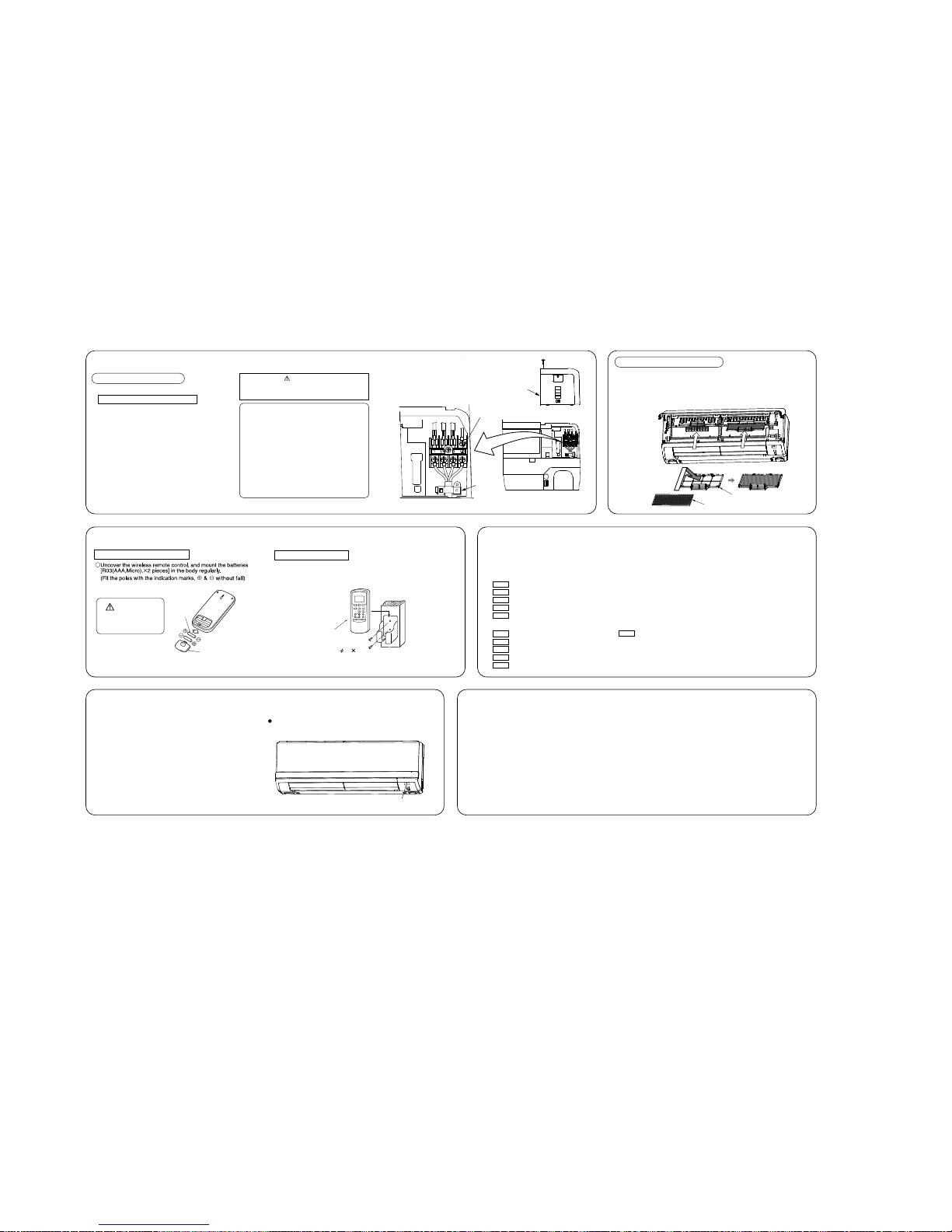
1. Open the air inlet panel and remove the air filters.
2. Install the filter holders, with the air-cleaning filters installed in the holders.
In the air conditioner.
• Each air-cleaning filter can be installed in the left or right filter holder.
3. Install the air filters and close the inlet panel.
After installation
The power supply voltage is correct as the rating.
No gas leaks from the joints of the operational valve.
Power cables and crossover wires are securely fixed to the terminal board.
Operational valve is fully open.
The pipe joints for indoor and outdoor pipes have been insulated.
Connection wiring,
Earth wiring
Outer tape
Refrigerant piping
Drain hose
Wood screw
Clamp
Cover the exterior portion with outer tape and
shape the piping so it will match the contours
of the route that the piping to take.
Also fix the wiring and pipings to the wall with
clamps.
Removing
① Remove the air inlet panel.
② Remove the 5 set screws.
③ Remove the 4 latches in the upper section.
④ Move the lower part of the panel forward and
push upwards to remove.
Fitting
① Do remove the air filter.
② Cover the body with the front panel.
③ Fit the 4 latches in the upper section.
④ Tighten the 5 set screws.
⑤ Fit the air filter.
⑥ Fit the air input panel.
Preparation of indoor unit
Installing the air-cleaning filters
① Open the air inlet panel.
② Remove the service panel.
③ Remove the wiring clamp
④ Connect the connecting wire securely to the terminal block.
1 ) Connect the connection wire securely to the terminal
block. If the wire is not affixed completely, contact will be
poor, and it is dangerous as the terminal block may heat
up and catch fire.
2 ) Take care not to confuse the terminal numbers for indoor
and outdoor connections.
3 ) Fix the connection wire using the wiring clamp.
⑤ Fix the connecting wire by wiring clamp.
⑥ Attach the service panel.
⑦ Close the air inlet panel.
Open/close and detachment/attachment of the air inlet panel
To open, pull the panel at both ends of lower part
and release latches, then pull up the panel until
you feel resistance.
(The panel stops at approx. 60 open position)
To close, hold the panel at both ends of lower
part to lower downward and push it slightly until
the latch works.
To remove, pull up the panel to the position
shown in right illustration and pull it toward you.
To install, insert the panel arm into the slot on the
front panel from the position shown in right
illustration, hold the panel at both ends of lower
part, lower it downward slowly, then push it
slightly until the latch warks.
Set screws
latch
Mounting of connecting wires
CAUTION
Conventionally, operate the remote control switch by holding in your hand.
Avoid installing it on a clay wall etc.
⑤ Wood screw
3.5 16
② Wireless remote control
⑥ Battery
INSTALLATION OF REMOTE CONTROL SWITCH
Mounting method of battery
Fixing to pillar or wall
Do not use new and
old batteries together.
Filter holder
Air-cleaning filter
Test run
Air conditioning operation is normal.
No abnormal noise.
Water drains smoothly.
Protective functions are not working.
The remote control is normal.
Operation of the unit has been explained to the customer.
(Three-minutes restart preventive timer)
When the air conditioner is restarted or when changing the operation, the unit
will not start operating for approximately 3 minutes.
This is to protect the unit and it is not a malfunction.
Check the following points again after completion of the installation, and before turning on the power. Conduct a test run again and ensure that the unit operates properly.
At the same time, explain to the customer how to use the unit and how to take care of the unit following the user's manual.
Unit ON/OFF button
① Remove the front panel and lid of control.
② There is a terminal (respectively marked with CNS) for the indoor control board.
In connecting an interface, connect to the respective terminal securely with the connection harness supplied
with an optional “Interface connection kit SC-BIKN-E” and fasten the connection harness onto the indoor control
box with the clamp supplied with the kit.
For more details, please refer to the user's manual of your “Interface connection kit SC-BIKN-E”.
How to remove the indoor unit from the installation board
Arrange the drain hose in a downward angle
Avoid the following drain piping.
Pour water to the drain pan located under the heat exchanger, and ensure that the water is discharged outdoor.
When the extended drain hose is indoor, always use a shield pipe (to be arranged by the user) and ensure it is
thermally insulated
Fixing of indoor unit
Since this air conditioner has been designed to collect dew drops on the rear
surface to the drain pan, do not attach the power cord above the gutter.
Drainage
Go through all installation steps and check if the
drainage is all right. Otherwise water leak may occur.
Higher than specified The drain hose
tip is in water.
Wavy The drain hose
tip is in the gutter.
The gap to the ground is
5 cm or less.
Odor from
the gutter
Shield pipe
Drain hose
Extended drain hose
When it is exposed indoor.
Terminal block
Service panel
Clamp
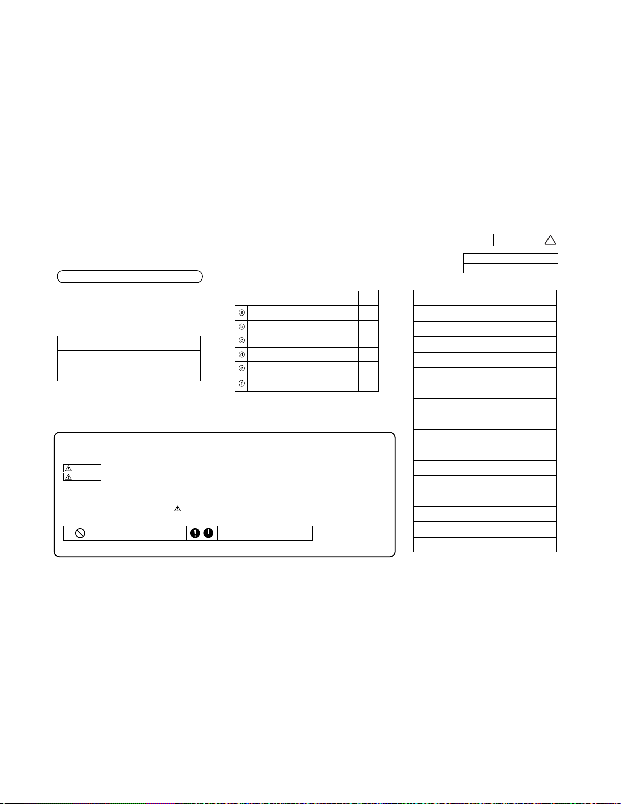
-
18 *
-
1.5.2 Installation of outdoor unit
Models SRC20ZIX-S, 25ZIX-S, 35ZIX-S
RWC012A030
Model 20・25・35
Designed for R410A refrigerant
PRECAUTIONS FOR SAFETY
◎
This installation manual deals with outdoor units and general installation specifications only. For indoor units, refer to the respective
installation manuals supplied with the units.
◎
Read this manual carefully before you set to installation work and carry it out according to the instructions contained in this manual.
●
When installing the equipment, carefully read the Precautions for safety and make sure that safety is maintained.
●
The safety items contain important information regarding safety. Be sure to follow them. The symbols used and their meanings are as follows.
WARNING
: Improper installation could result in serious accident causing death, serious injury or environmental pollution.
CAUTION
: Improper installation could result in serious accident.
●
After installation,along with confirming that no abnormalities were seen from the operation test. Explain operating methods as well as maintenance
methods to the user of this equipment, based on the owner’s manual.
●
Ask the customer to keep this manual together with the operation manual.
●
In installing the unit, you must also take thorough safety precautions to protect your person.
A failure to observe any safety instruction listed under “ Caution” can also result in a serious consequence depending on the circumstances.
Please observe all these instructions, because they include important points concerning safety.
●
The meanings of “Marks” used here are as follows:
●
Beware of danger from a dropped tool or the like in installing the unit in an elevated position.
●
When the air conditioning unit makes abnormal sounds in operation, consult with your dealer.
Never do it under any circumstances. Always do it according to the instruction.
Check before installation work
●
Model name and power source
●
Refrigerant piping length
●
Piping, wiring and miscellaneous small parts
●
Indoor unit installation manual
①
②
1
1
Accessories for outdoor unit
Gromet (Heat pump type only)
Drain elbow (Heat pump type only)
1
1
1
1
1
1
Q’ty
Option parts
Sealing plate
Sleeve
Inclination plate
Putty
Drain hose (extention hose)
Piping cover
(for insulation of connection piping)
Necessary tools for the installation work
1
2
3
4
5
6
7
8
9
10
11
12
13
14
15
16
Plus headed driver
Knife
Saw
Tape measure
Hammer
Spanner wrench
Torque wrench (14.0〜 62.0N・m (1.4 〜 6.2kgf・m))
Hole core drill (65mm in diameter)
Wrench key (Hexagon) [ 4 m/m]
Vacuum pump
Vacuum pump adapter
(Anti-reverse flow type)
Gauge manifold (Designed specifically for R410A)
Charge hose (Designed specifically for R410A)
Flaring tool set (Designed specifically for R410A)
Gas leak detector (Designed specifically for R410A)
Gauge for projection adjustment
(Used when flare is made by using conventional flare tool)
(Designed specifically for R410A)
a
-
19
-
2. REFRIGERANT PIPING WORK
1) Restrictions on unit installation and use
●Check the following points in light of the indoor unit specifications and the installation site.
●
Observe the following restrictions on unit installation and use. Improper installation can result in a compressor failure or performance degradation
30m or less
20m or less
20m or less
PRECAUTIONS FOR SAFETY
RWC012A030
Model 20・25・35
Designed for R410A refrigerant
●
To disc onnect the a ppliance from the mains s upply this ap pliance must be connected to the main s by means of a circuit b reaker or a switc h
(use a recognized 16A) with a contact separation of at least 3mm.
●
The appliance shall be installed in accordance with national wiring regulations.
●
This system should be applied to places as households, residences and the like. Application to inferior environment such as engineering shop
could cause equipment malfunction.
●
Ask your dealer or a specialized service provider to install the unit.
Improper installation work performed on the part of a user can result in a water leak, electric shock or fire.
●
Carry out installation work properly according to this installation manual.
Improper installation work can result in a water leak, electric shock, or fire.
●
Always turn off power before you work inside the unit such as for installation or servicing.
A failure to observe this instruction can result in an electric shock.
●
Install the unit securely onto a structure that is strong enough to sustain its weight.
Insufficient strength or improper installation can cause a fall of the unit and resultant injury.
●
Electrical installation work must be performed according to the installation manual as dedicated circuits exclusively for the air conditioning system in
compliance with the applicable “Technical standards for electrical installation” and “Indoor wiring regulations.”
A defect in power supply circuits such as insufficient capacity or improper installation can cause an electrical shock or fire.
●
Always connect between indoor and outdoor units securely with specified cables. Never use an intermediate connection or stranded wire for this purpose.
Fasten cables securely so that the terminal block may not be subject to external force working through cables.
Improper connection or fastening can cause heat generation and a resultant fire.
●
Neatly arrange the cables connecting between indoor and outdoor units so that they may not get loose, and put on the lid and/or service panel securely.
Improper installation can cause heat generation at terminal connections and a resultant fire or electric shock.
●
Use only parts supplied with the unit and approved supply parts for installation work.
A failure to use genuine parts approved by the manufacturer may result in a fall of the unit, a water leak, a fire, an electric shock, a refrigerant leak, substandard performance or a control failure.
●
If refrigerant gas leaks during installation work, ventilate the room.
Refrigerant gas, if it comes into contact with bare fire, can cause the generation of a toxic gas.
●
Use pipes, flare nuts and tools specifically designed for R410A.
The diversion of existing materials (designed for R22) can result in a unit failure as well as a serious accident such as refrigeration cycle rupture or injury.
●
In carrying out a pump-down process, stop the compressor before you detach the refrigerant pipe.
If you detach the pipe with the compressor running and the operation valves (liquid and gas sides) open, an abnormal pressure build-up will occur in the refrigeration cycle, which
can result in pipe rupture or injury.
●
In installing the unit, be sure to attach the refrigerant pipe before operating the compressor.
If you run the compressor without attaching the refrigerant pipe and with the operation valves (liquid and gas sides) open, you may incur frost bite or injury from an abrupt
refrigerant outflow. An abnormal pressure build-up may also occur in the refrigeration cycle as a result of the inhalation of air, which can result in pipe rupture or injury.
●
Tighten a flare nut with a torque wrench in a specified manner.
Over-tightening a flare nut can cause a refrigerant gas leak from breakage after years of operation and the generation of a toxic product, if refrigerant gas comes into contact with bare fire.
●
In inserting the power cable plug, make sure that no anomalies such as dust deposits, socket clogging or wobble are found in both the plug and outlet and
insert the plug fully to the roots of its blades.
Dust deposits, clogging or wobble can result in an electric shock or fire. If the outlet is loose, change it with a new one.
●
Never open the operation valves (either liquid or gas side) until refrigerant pipe installation work, an air-tightness test and an air purge are completed.
A failure to observe this instruction can result in frost bite or injury from an abrupt refrigerant outflow. If refrigerant gas leaks during installation work, immediately stop pipe
blazing and other work and ventilate the room.
●
Do not run the drain piping directly into the sewer where a toxic gas such as sulfuric gas is generated.
This will pose a risk of a toxic gas flowing back into the room. This can also cause the corrosion of the indoor unit and a resultant unit failure or refrigerant leak.
●
You must collect, bring back and shred or otherwise properly dispose of all packaging materials, expanded polystyrene, bands, vinyl bags and so on used for
the transpiration of the indoor and outdoor units after installation work.
●
In installing or transferring an air conditioning system, never allow air or other foreign matters than specified refrigerant (R410A) to get into the refrigerant cycle (piping).
If air or other foreign matters gets into the refrigerant cycle, an abnormal pressure build-up will occur, which can result in pipe rupture or injury.
●
Never modify the power cord, introduce an intermediate connection or connect it in a daisy chain.
A failure to observe this instruction can result in a fire or electric shock from improper contact, improper insulation, excessive current beyond rating, etc.
●
Never bundle, wind or modify the power cord. Do not step onto the power plug or otherwise deform it.
A failure to observe this instruction can result in heat generation or ignition.
●
Ensure that the unit is properly grounded.
Do not connect the grounding wire to a gas pipe, water pipe, lightning rod, or telephone ground wire.
If a defect is in a ground, it will become a cause of an electric shock at the time of failure or a short circuit.
Notabilia as a unit designed for R410A
●
Do not use any refrigerant other than R410A. R410A will rise to pressure about 1.6 times higher than that of a conventional refrigerant.
A cylinder containing R410A has a pink indication mark on the top.
●
A unit designed for R410A has adopted a different size indoor unit operation valve charge port and a different size check joint provided in the unit to prevent the charging of a wrong refrigerant by mistake.
The processed dimension of the flared part of a refrigerant pipe and a flare nut's parallel side measurement have also been altered to raise strength against pressure.
Accordingly, you are required to arrange dedicated R410A tools listed in the table on the right before installing or servicing this unit.
●
Do not use a charge cylinder. The use of a charge cylinder will cause the refrigerant composition to change, which results in performance degradation.
●
In charging refrigerant, always take it out from a cylinder in the liquid phase.
●
All indoor units must be models designed exclusively for R410A. Check connectable indoor unit models in a catalog, etc. (A wrong indoor unit, if connected into the system, will impair proper system operation)
◎This installation manual deals with outdoor units and general installation specifications only. For indoor units, refer to the respective
installation manuals supplied with the units.
◎Read this manual carefully before you set to installation work and carry it out according to the instructions contained in this manual.
●
When installing the equipment, carefully read the Precautions for safety and make sure that safety is maintained.
●
The safety items contain important information regarding safety. Be sure to follow them. The symbols used and their meanings are as follows.
WARNING
: Improper installation could result in serious accident causing death, serious injury or environmental pollution.
CAUTION
: Improper installation could result in serious accident.
●
After installation, along with confirming that no abnormalities were seen from the operation test. Explain operating methods as well as maintenance
methods to the user of this equipment, based on the owner’s manual.
●
Ask the customer to keep this manual together with the operation manual.
●
In installing the unit, you must also take thorough safety precautions to protect your person.
A failure to observe any safety instruction listed under “ Caution” can also result in a serious consequence depending on the circumstances.
Please observe all these instructions, because they include important points concerning safety.
●
The meanings of “Marks” used here are as follows:
●
Beware of danger from a dropped tool or the like in installing the unit in an elevated position.
●
When the air conditioning unit makes abnormal sounds in operation, consult with your dealer.
1. HAULAGE AND INSTALLATION
(Take particular care in carrying in or moving the unit, and always perform such an operation with two or more persons.)
CAUTION
When a unit is hoisted with slings for haulage, take into consideration the offset of its gravity center position.
If not properly balanced, the unit can be thrown off-balance and fall.
1) Delivery
●
Deliver the unit as close as possible to the installation site before removing it from
the packaging.
●
When you have to unpack the unit for a compelling reason before you haul it to the
installation point, hoist the unit with nylon slings or ropes and protection pads so that
you may not damage the unit.
2) Portage
●
The right hand side of the unit as viewed from the front (diffuser side) is heavier.
A person carrying the right hand side must take heed of this fact. A person carrying
the left hand side must hold with his right hand the handle provided on the front panel
of the unit and with his left hand the corner column section
.
3) Selecting the installation location
Be careful of the following conditions and choose an installation place.
〇
Where air is not trapped.
〇
Where the installation fittings can be firmly installed.
〇
Where wind does not hinder the intake and outlet pipes.
〇
Out of the heat range of other heat sources.
〇
A place where stringent regulation of electric noises is applicable.
〇 Where it is safe for the drain water to be discharged.
〇
Where noise and hot air will not bother neighboring residents.
〇
Where snow will not accumulate.
〇
Where strong winds will not blow against the outlet pipe.
〇
A place where no TV set or radio receiver is placed within 5m.
(If electrical interference is caused, seek a place less likely to cause the problem)
〇
If a operation is conducted when the outdoor air temperature is -5℃lower, the outdoor unit should be installed
at a place where it is not influenced by natural wind.
〇
Where it is likely that the unit is subjected to strong winds, provide wind guards according to the following guidelines
.
Strong winds can cause performance degradation, an accidental stop due to a rise of high pressure and a broken fan
.
1.Place the unit outlet pipe perpendicular to the wind direction.
Heavy
Wind direction
Wind direction
2.Install so the direction of the air from the blowing outlet will be
perpendicular to the direction of the wind.
CAUTION
●
The use restrictions appearing in the table above are applicable to the standard pipe size combinations shown in the table below.
Where an existing pipe system is utilized, different one-way pipe length restrictions should apply depending on its pipe size.
For more information, please see “
5. UTILIZATION OF EXISTING PIPING.
”
Restrictions
Dimensional restrictions
Marks appearing in the drawing on the right
Main pipe length
When the outdoor unit is positioned higher,
When the outdoor unit is positioned lower,
Elevation difference between
indoor and outdoor units
Pad
Never do it under any circumstances. Always do it according to the instruction.
WARNING
Over 500mm
●
Take sufficient care so that you may not incur injury from heat exchanger fins,
pipe flares and screws during work.
●
Install drain piping according to the installation manual to ensure good drainage,
and give it heat insulation to prevent condensation.
Improper installation can result in a flood of water in the room and soaked household effects.
●
When the unit is installed in a humid or damp place, the installation of an earth
leakage breaker is essential.
A failure to install an earth leakage breaker can cause an electric shock.
●
When the air conditioning system is installed in a room equipped with a ventilating
fan and it is used (for a cooling or dehumidifying operation) simultaneously
with the ventilating fan, the room may have a negative air pressure relative to the
exterior, which can cause a reverse flow of drain water. Make sure that the room
has an opening that allows the inflow of as much air as discharged by the
ventilation fan. (For example, open the door a little) Similarly, provide an adequate
opening, if a room has a negative air pressure relative to the exterior due to the effect
of winds in a high-rise condominium building or the like.
●
Secure a service space for inspection and maintenance as specified in the manual.
An insufficient service space can result in a fall from the installation point and resultant injury.
●
When the outdoor unit is installed on a roof top or in an elevated position,
provide permanent ladders and handrails along the access path and fences or
handrails surrounding the outdoor unit.
●
Dress the refrigerant piping with a heat insulation material to prevent condensation.
Improper heat insulation given to refrigerant piping for condensation prevention can result in
leaking or dripping water soaking household effects.
●
In removing packaging materials, take sufficient care so as not to damage the
contents or incur injury from such work.
●
Do not install the unit in the place where a risk of inflammable gas leaks exists.
Should gas leak and gather around the unit, it can cause the ignition of gas.
●
Do not touch the air intake and aluminum fins of the outdoor unit.
You may incur injury if you touch them.
●
Do not install the outdoor unit in a place where small animals are likely to inhabit.
If they enter the unit and touch electrical parts inside, they may cause a unit failure or fire.
Please ask the customer to keep the surroundings clean.
●
Do not install the outdoor unit where its fan winds directly hit a plant etc.
Fan winds can affect adversely to the plant etc.
●
Do not operate the outdoor unit with any article placed on it.
A failure to observe this instruction can result in a fall of the article and resultant property
damage or personal injury.
CAUTION
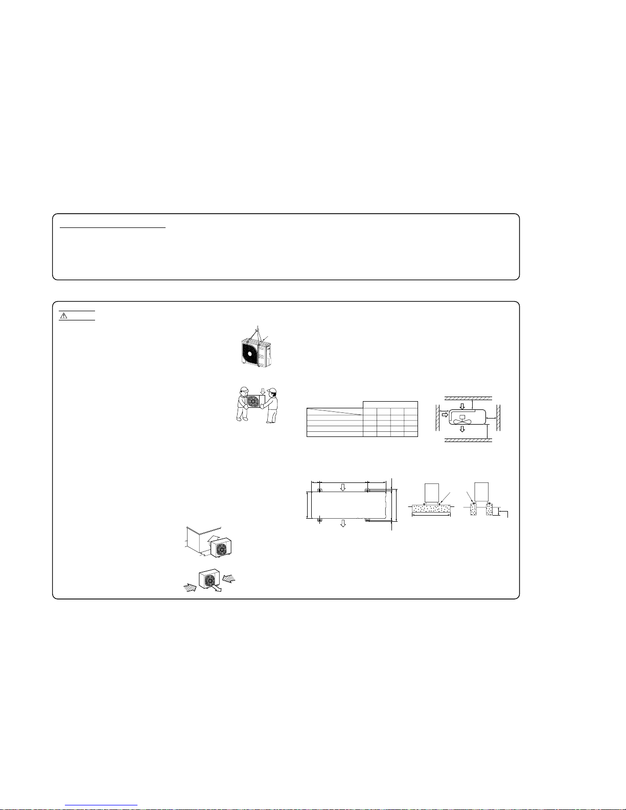
-
20
-
Notabilia as a unit designed for R410A
●
Do not use any refrigerant other than R410A. R410A will rise to pressure about 1.6 times higher than that of a conventional refrigerant.
A cylinder containing R410A has a pink indication mark on the top.
●
A unit designed for R410A has adopted a different size indoor unit operation valve charge port and a different size check joint provided in the unit to prevent the charging of a wrong refrigerant by mistake.
The processed dimension of the flared part of a refrigerant pipe and a flare nut's parallel side measurement have also been altered to raise strength against pressure.
Accordingly, you are required to arrange dedicated R410A tools listed in the table on the right before installing or servicing this unit.
●
Do not use a charge cylinder. The use of a charge cylinder will cause the refrigerant composition to change, which results in performance degradation.
●
In charging refrigerant, always take it out from a cylinder in the liquid phase.
●
All indoor units must be models designed exclusively for R410A. Check connectable indoor unit models in a catalog, etc. (A wrong indoor unit, if connected into the system, will impair proper system operation)
1. HAULAGE AND INSTALLATION
(Take particular care in carrying in or moving the unit, and always perform such an operation with two or more persons.)
②
Notabilia for installation
Intake
The height of a wall is 1200mm or less.
(
service
space
)
Intake
Outlet
Fasten with bolts
(M10-12)
Use a thicker block toanchor deeper.
Use a long block to
extend the width.
CAUTION
When a unit is hoisted with slings for haulage, take into consideration the offset of its gravity center position.
If not properly balanced, the unit can be thrown off-balance and fall.
1) Delivery
●
Deliver the unit as close as possible to the installation site before removing it from
the packaging.
●
When you have to unpack the unit for a compelling reason before you haul it to the
installation point, hoist the unit with nylon slings or ropes and protection pads so that
you may not damage the unit.
2) Portage
●
The right hand side of the unit as viewed from the front (diffuser side) is heavier.
A person carrying the right hand side must take heed of this fact. A person carrying
the left hand side must hold with his right hand the handle provided on the front panel
of the unit and with his left hand the corner column section
.
3) Selecting the installation location
Be careful of the following conditions and choose an installation place.
〇 Where air is not trapped.
〇 Where the installation fittings can be firmly installed.
〇 Where wind does not hinder the intake and outlet pipes.
〇 Out of the heat range of other heat sources.
〇 A place where stringent regulation of electric noises is applicable.
〇 Where it is safe for the drain water to be discharged.
〇 Where noise and hot air will not bother neighboring residents.
〇 Where snow will not accumulate.
〇 Where strong winds will not blow against the outlet pipe.
〇 A place where no TV set or radio receiver is placed within 5m.
(If electrical interference is caused, seek a place less likely to cause the problem)
〇 If a operation is conducted when the outdoor air temperature is -5℃lower, the outdoor unit should be installed
at a place where it is not influenced by natural wind.
〇
Where it is likely that the unit is subjected to strong winds, provide wind guards according to the following guidelines
.
Strong winds can cause performance degradation, an accidental stop due to a rise of high pressure and a broken fan
.
4) Installation space
●
Walls surrounding the unit in the four sides are not acceptable.
●
There must be a 1-meter or larger space in the above.
●
When more than one unit are installed side by side, provide a 250mm or wider interval between them as a
service space. In order to facilitate servicing of controllers, please provide a sufficient space between units
so that their top plates can be removed easily.
●
Where a danger of short-circuiting exists, install guide louvers.
●
When more than one unit are installed, provide sufficient intake space consciously so that short-circuiting may not occur
.
●
Where piling snow can bury the outdoor unit, provide proper snow guards.
1.Place the unit outlet pipe perpendicular to the wind direction.
L3
L2
L4
L1
Model 20, 25, 35
Example installation
Size
L1
L2
L3
L4
Ⅰ
Open
100
100
250
Ⅱ
280
75
80
Open
Ⅲ
280
Open
80
250
Ⅳ
180
Open
80
Open
(mm)
①
Anchor bolt fixed position
●
In installing the unit, fix the unit’s legs with bolts specified on the left.
●
The protrusion of an anchor bolt on the front side must be kept within 15 mm.
●
Securely install the unit so that it does not fall over during earthquakes or strong winds, etc.
●
Refer to the above illustrations for information regarding concrete foundations.
●
Install the unit in a level area. (With a gradient of 5 mm or less.)
Improper installation can result ina compressorfailure, broken piping withinthe unitand abnormal noise generation.
Heavy
Wind direction
Wind direction
2.Install so the direction of the air from the blowing outlet will be
perpendicular to the direction of the wind.
5) Installation
Pad
Over 500mm
Intake
Outlet
312.5
24.314.8
288.8
111
510 157.8
351.6

-
21
-
2. REFRIGERANT PIPING WORK
1) Restrictions on unit installation and use
●Check the following points in light of the indoor unit specifications and the installation site.
●Observe the following restrictions on unit installation and use. Improper installation can result in a compressor failure or performance degradation
.
●Additional refrigerant charge is not required at all.
2) Determination of pipe size
●Determine refrigerant pipe size pursuant to the following guidelines based on the
indoor unit specifications.
15m or less
10m or less
10m or less
L
H
H
Gas pipe
Liquid pipe
φ9.52 φ6.35
Flare Flare
φ9.52 φ6.35
φ9.52 φ6.35
Notabilia as a unit designed for R410A
●
Do not use any refrigerant other than R410A. R410A will rise to pressure about 1.6 times higher than that of a conventional refrigerant.
A cylinder containing R410A has a pink indication mark on the top.
●
A unit designed for R410A has adopted a different size indoor unit operation valve charge port and a different size check joint provided in the unit to prevent the charging of a wrong refrigerant by mistake.
The processed dimension of the flared part of a refrigerant pipe and a flare nut's parallel side measurement have also been altered to raise strength against pressure.
Accordingly, you are required to arrange dedicated R410A tools listed in the table on the right before installing or servicing this unit.
●
Do not use a charge cylinder. The use of a charge cylinder will cause the refrigerant composition to change, which results in performance degradation.
●
In charging refrigerant, always take it out from a cylinder in the liquid phase.
●
All indoor units must be models designed exclusively for R410A. Check connectable indoor unit models in a catalog, etc. (A wrong indoor unit, if connected into the system, will impair proper system operation)
1. HAULAGE AND INSTALLATION
(Take particular care in carrying in or moving the unit, and always perform such an operation with two or more persons.)
②
Notabilia for installation
Intake
The height of a wall is 1200mm or less.
(
service
space
)
Intake
Outlet
Fasten with bolts
(M10-12)
Use a thicker block toanchor deeper.
Use a long block to
extend the width.
CAUTION
When a unit is hoisted with slings for haulage, take into consideration the offset of its gravity center position.
If not properly balanced, the unit can be thrown off-balance and fall.
1) Delivery
●
Deliver the unit as close as possible to the installation site before removing it from
the packaging.
●
When you have to unpack the unit for a compelling reason before you haul it to the
installation point, hoist the unit with nylon slings or ropes and protection pads so that
you may not damage the unit.
2) Portage
●
The right hand side of the unit as viewed from the front (diffuser side) is heavier.
A person carrying the right hand side must take heed of this fact. A person carrying
the left hand side must hold with his right hand the handle provided on the front panel
of the unit and with his left hand the corner column section
.
3) Selecting the installation location
Be careful of the following conditions and choose an installation place.
〇 Where air is not trapped.
〇 Where the installation fittings can be firmly installed.
〇 Where wind does not hinder the intake and outlet pipes.
〇 Out of the heat range of other heat sources.
〇 A place where stringent regulation of electric noises is applicable.
〇 Where it is safe for the drain water to be discharged.
〇 Where noise and hot air will not bother neighboring residents.
〇 Where snow will not accumulate.
〇 Where strong winds will not blow against the outlet pipe.
〇 A place where no TV set or radio receiver is placed within 5m.
(If electrical interference is caused, seek a place less likely to cause the problem)
〇 If a operation is conducted when the outdoor air temperature is -5℃lower, the outdoor unit should be installed
at a place where it is not influenced by natural wind.
〇
Where it is likely that the unit is subjected to strong winds, provide wind guards according to the following guidelines
.
Strong winds can cause performance degradation, an accidental stop due to a rise of high pressure and a broken fan
.
4) Installation space
●
Walls surrounding the unit in the four sides are not acceptable.
●
There must be a 1-meter or larger space in the above.
●
When more than one unit are installed side by side, provide a 250mm or wider interval between them as a
service space. In order to facilitate servicing of controllers, please provide a sufficient space between units
so that their top plates can be removed easily.
●
Where a danger of short-circuiting exists, install guide louvers.
●
When more than one unit are installed, provide sufficient intake space consciously so that short-circuiting may not occur
.
●
Where piling snow can bury the outdoor unit, provide proper snow guards.
1.Place the unit outlet pipe perpendicular to the wind direction.
L3
L2
L4
L1
Model 20, 25, 35
Example installation
Size
L1
L2
L3
L4
Ⅰ
Open
100
100
250
Ⅱ
280
75
80
Open
Ⅲ
280
Open
80
250
Ⅳ
180
Open
80
Open
(mm)
①
Anchor bolt fixed position
●
In installing the unit, fix the unit’s legs with bolts specified on the left.
●
The protrusion of an anchor bolt on the front side must be kept within 15 mm.
●
Securely install the unit so that it does not fall over during earthquakes or strong winds, etc.
●
Refer to the above illustrations for information regarding concrete foundations.
●
Install the unit in a level area. (With a gradient of 5 mm or less.)
Improper installation can result ina compressorfailure, broken piping withinthe unitand abnormal noise generation.
Heavy
Wind direction
Wind direction
2.Install so the direction of the air from the blowing outlet will be
perpendicular to the direction of the wind.
5) Installation
L
H
Outdoor unit
Indoor unit
CAUTION
●
Theuse restrictions appearing inthe table aboveare applicable to the standard pipesize combinationsshown inthe tablebelow.
Restrictions
Dimensional restrictions
Marks appearing in the drawing on the right
Main pipe length
When the outdoor unit is positioned higher,
When the outdoor unit is positioned lower,
Elevation difference between
indoor and outdoor units
Outdoor unit connected
Refrigerant piping (branch pipeL)
Indoor unit connected
Plug the end of the pipe with tape, or other
material, and fill the pipe with nitrogen gas.
Only use nitrogen gas (N2)
Taping
<N2>
Nitrogen
Brazing
Station valve
Primary side Secondary side
0.5MPa
Hand
Relief valve
Nitrogen
gas
Brazing must be performed under a nitrogen gas flow.
Without nitrogen gas, a large quantity of foreign matters (oxidized film) are created,
causing a critical failure from capillary tube or expansion valve clogging.
About brazing
When pipe is brazing.
3) Refrigerant pipe wall thickness and material
●
Select refrigerant pipes of the table shown on the right wall thickness and
material as specified for each pipe size.
Pipe diameter [mm]
Minimum pipe wall thickness [mm]
Pipe material*
6.35
0.8
O-type pipe
9.52
0.8
O-type pipe
NOTE
*Phosphorus deoxidized seamless copper pipe ICS 23.040.15, ICS 77.150.30
●
Select pipes having a wall thickness larger than the specified
minimum pipe thickness.
Pad
Over 500mm
Model 20, 25, 35
Intake
Outlet
312.5
24.314.8
288.8
111
510 157.8
351.6
4. ELECTRICAL WIRING WORK
Take care so that installed pipes may not touch
components within a unit.
If touching with an internal component
, it will generate abnormal sounds and/or vibrations.
4) On-site piping work
IMPORTANT
How to remove the side cover
●
Carry out the on site piping work with the operation valve fully closed.
●
Give sufficient protection to a pipe end (compressed and blazed, or with an adhesive tape) so
that water or foreign matters may not enter the piping.
●
Bend a pipe to a radius as large as practical.(R100〜R150) Do not bend a pipe repeatedly to correct
its form.
●
Flare connection is used between the unit and refrigerant pipe. Flare a pipe after engaging a
flare nut onto it. Flare dimensions for R410A are different from those for conventional R407C.
Although we recommend the use of flaring tools designed specifically for R410A, conventional
flaring tools can also be used by adjusting the measurement of protrusion B with a protrusion
control gauge.
●
Tighten a flare joint securely with a double spanner.
Please remove the screw of a side cover and remove to the front.
A
B
Flared pipe end : A (mm)
φ6.35
φ9.52
Copper
pipe outer
diameter
0
ー0.4
A
9.1
13.2
Copper pipe protrusion for flaring : B
(mm)
φ6.35
φ9.52
Copper
pipe outer
diameter
In the case of a rigid (clutch) type
With an R410A tool With a conventional tool
0〜0.5 1.0〜1.5
Screw
Side cover
Electrical installation work must be performed by an electrical installation service provider qualified by a power provider of the country.
Electrical installation work must be executed according to the technical standards and other regulations applicable to electrical installations in the country.
●
Do not use any supply cord lighter than one specified in parentheses for each type below.
- braided cord (code designation 60245 IEC 51),
- ordinary tough rubber sheathed cord (code designation 60245 IEC 53)
- flat twin tinsel cord (code designation 60227 IEC 41);
Use polychloroprene sheathed flexible cord (code designation 60245 IEC57) for supply cords of parts of appliances for outdoor use.
●
Ground the unit. Do not connect the grounding wire to a gas pipe, water pipe, lightning rod or telephone grounding wire
If impropery grounded, an electric shock or malfunction may result.
●
A grounding wire must be connected before connecting the power cable. Provide a grounding wire longer than the power cable.
●
The installation of an impulse withstanding type earth leakage breaker is necessary. A failure to install an earth leakage breaker can result in an
acccident such as an electric shock or a fire.
●
Do not turn on the power until the electrical work is completeted .
●
Do not use a condensive capacitor for power factor improvement under any circumstances. (It dose not improve power factor, while it can cause
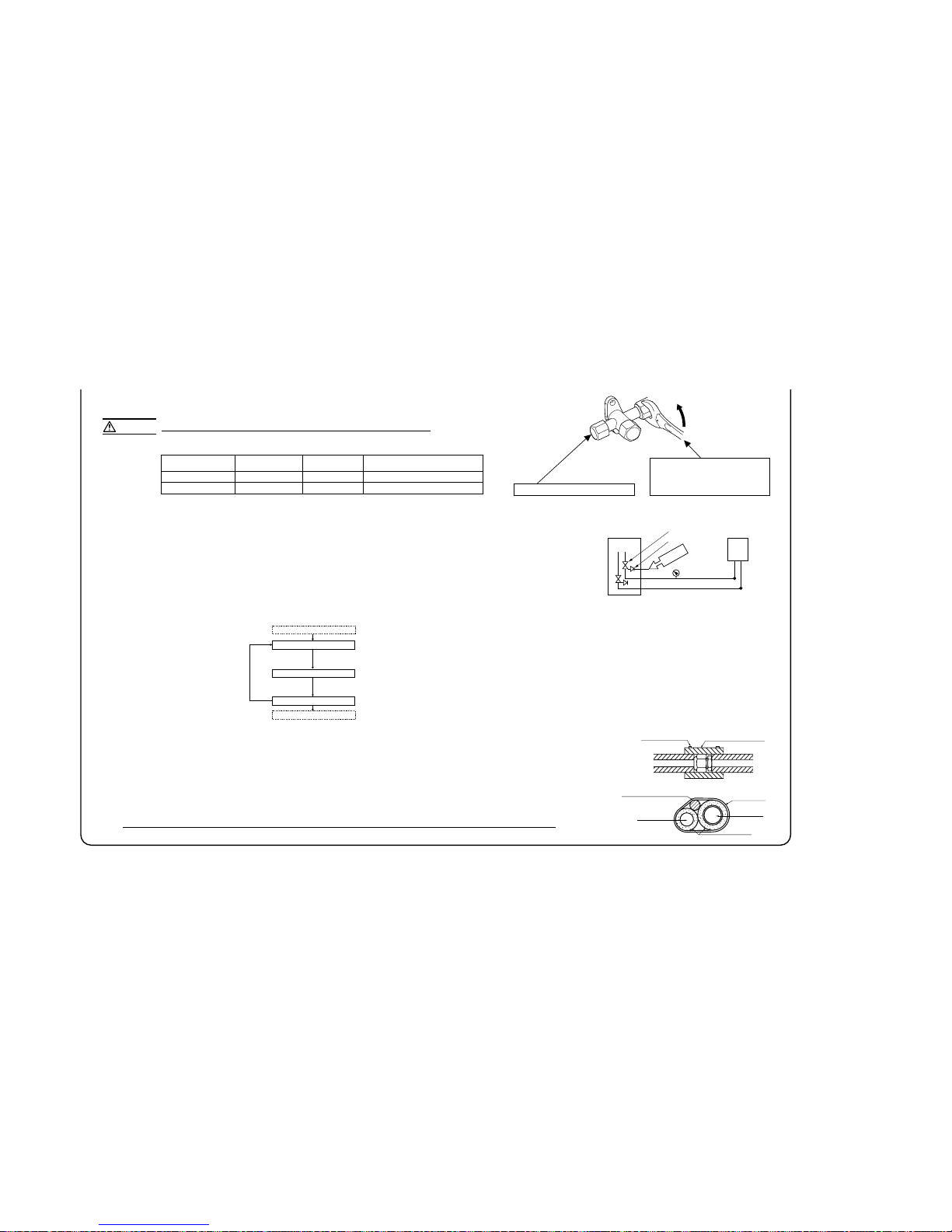
-
22
-
Wires for connecting indoor
and outdoor units
Exterior tape
Gas piping
Insulation
Liquid piping
Band (accessory)
Pipe cover (accessory)
Cable name plate
Power supply terminal block
○
It holds cables in place and protect the terminal
connection from external force.
○
This clamp is for the cable in the outside
diameter 9~15mm.
Please adjust it when not suitable.
○
Please be sure to carry out D-type (type III)
grounding work.
○
It has stuck on the lid of a control box.
Grounding terminal
Cable clamp
Indoor - Outdoor
connecting wire
Power cable
Please connect the earthed line of indoor and outdoor
connecting wire to a bracket part of the illustration
power cable, indoor - outdoor connecting wire circuit diagram
4. ELECTRICAL WIRING WORK
7) Heating and condensation prevention
(1) Dress refrigerant pipes (both gas and liquid pipes) for heat insulation and prevention of dew condensation.
- Improper heat insulation/anti-dew dressing can result in a water leak or dripping causing damage to household effects, etc.
(2) Use a heat insulating material that can withstand 120℃ or a higher temperature. Poor heat insulating capacity can cause heat insulation problems or cable
deterioration.
- All gas pipes must be securely heat insulated in order to prevent damage from dripping water that comes from the condensation formed on them during a cooling operation
or personal injury from burns because their surface can reach quite a high temperature due to discharged gas flowing inside during a heating operation.
- Wrap indoor units’ flare joints with heat insulating parts (pipe cover) for heat insulation (both gas and liquid pipes).
- Give heat insulation to both gas and liquid side pipes. Bundle a heat insulating material and a pipe tightly together so that no gaps may be left between them and wrap them
together with a connecting cable by a dressing tape.
- Both gas and liquid pipes need to be dressed with 20 mm or thicker heat insulation materials above the ceiling where relative humidity exceeds 70%.
Take care so that installed pipes may not touch
components within a unit.
If touching with an internal component
, it will generate abnormal sounds and/or vibrations.
4) On-site piping work
IMPORTANT
How to remove the side cover
●
Carry out the on site piping work with the operation valve fully closed.
●
Give sufficient protection to a pipe end (compressed and blazed, or with an adhesive tape) so
that water or foreign matters may not enter the piping.
●
Bend a pipe to a radius as large as practical.(R100〜R150) Do not bend a pipe repeatedly to correct
its form.
●
Flare connection is used between the unit and refrigerant pipe. Flare a pipe after engaging a
flare nut onto it. Flare dimensions for R410A are different from those for conventional R407C.
Although we recommend the use of flaring tools designed specifically for R410A, conventional
flaring tools can also be used by adjusting the measurement of protrusion B with a protrusion
control gauge.
●
Tighten a flare joint securely with a double spanner.
Please remove the screw of a side cover and remove to the front.
A
B
Flared pipe end : A (mm)
φ6.35
φ9.52
Copper
pipe outer
diameter
0
ー0.4
A
9.1
13.2
Copper pipe protrusion for flaring : B
(mm)
φ6.35
φ9.52
Copper
pipe outer
diameter
In the case of a rigid (clutch) type
With an R410A tool With a conventional tool
0〜0.5 1.0〜1.5
CAUTION
Do not apply force beyond proper fastening torque in tightening the flare nut.
Fix both liquid and gas service valves at the valve main bodies as illustrated on the right, and then fasten them,
applying appropriate fastening torque.
Tightening angle (°)
Tightening torque (N-m)
φ6.35 (1/4")
φ9.52 (3/8")
14〜18
34〜42
45〜60
30〜45
150
200
Use a torque wrench. If a torque wrench is
not available, fasten the flare nut manually
first and then tighten it further, using the
left table as a guide.
Recommended length of a tool handle (mm)Operation valve size (mm)
5) Air tightness test
① Although outdoor and indoor units themselves have been tested for air tightness at the factory, check the connecting pipes after the installation work for air tightness
from the operation valve’s check joint equipped on the outdoor unit side. While conducting a test, keep the operation valve shut all the time.
a) Raise the pressure to 0.5 MPa, and then stop. Leave it for five minutes to see if the pressure drops.
b) Then raise the pressure to 1.5 MPa, and stop. Leave it for five more minutes to see if the pressure drops.
c) Then raise the pressure to the specified level (4.15 MPa), and record the ambient temperature and the pressure.
d) If no pressure drop is observed with an installation pressurized to the specified level and left for about one day, it is acceptable. When the ambient Temperature fall
1℃, the pressure also fall approximately 0.01 MPa. The pressure, if changed, should be compensated for.
e) If a pressure drop is observed in checking e) and a) – d), a leak exists somewhere. Find a leak by applying bubble test liquid to welded parts and flare joints and
repair it. After repair, conduct an air-tightness test again.
② In conducting an air-tightness test, use nitrogen gas and pressurize the system with nitrogen gas from the gas side. Do not use a medium other than nitrogen gas
under any circumstances.
Gas side
operation valve
Check joint
Pressur
ize
Close
Outdoor unit
Indoor unit
<Work flow>
6) Evacuation
Pay attention to the following points in addition to the above for the R410A and
compatible machines.
○ To prevent a different oil from entering, assign dedicated tools, etc. to each refrigerant
type. Under no circumstances must a gauge manifold and a charge hose in particular
be shared with other refrigerant types (R22, R407C, etc.).
○
Use a counterflow prevention adapter to prevent vacuum pump oil from entering the
refrigerant system.
Airtighteness test completed
Fill refrigerant
Vacuum gauge check
Vacuuming completed
Vacuuming begins
Run the vacuum pump for at least one hour after the vacuum
gauge shows -101kPa or lower. (-755mmHg or lower)
Confirm that the vacuum gauge indicator does not rise even if
the system is left for one hour or more.
When the system has remaining moisture
inside or a leaky point, the vacuum gauge
indicator will rise.
Check the system for a leaky point and
then draw air to create a vacuum again.
Screw
Side cover
Do not hold the valve cap area with a spanner.
Electrical installation work must be performed by an electrical installation service provider qualified by a power provider of the country.
Electrical installation work must be executed according to the technical standards and other regulations applicable to electrical installations in the country.
●
Do not use any supply cord lighter than one specified in parentheses for each type below.
- braided cord (code designation 60245 IEC 51),
- ordinary tough rubber sheathed cord (code designation 60245 IEC 53)
- flat twin tinsel cord (code designation 60227 IEC 41);
Use polychloroprene sheathed flexible cord (code designation 60245 IEC57) for supply cords of parts of appliances for outdoor use.
●
Ground the unit. Do not connect the grounding wire to a gas pipe, water pipe, lightning rod or telephone grounding wire
If impropery grounded, an electric shock or malfunction may result.
●
A grounding wire must be connected before connecting the power cable. Provide a grounding wire longer than the power cable.
●
The installation of an impulse withstanding type earth leakage breaker is necessary. A failure to install an earth leakage breaker can result in an
acccident such as an electric shock or a fire.
●
Do not turn on the power until the electrical work is completeted .
●
Do not use a condensive capacitor for power factor improvement under any circumstances. (It dose not improve power factor, while it can cause
an abnormal overheat accident)
●
For power supply cables, use conduits.
●
Do not layelectronic control cables (remote controland signaling wires) and other cablestogether outside the unit. Layingthem together can result
in the malfunctioning or a failure of the unit due to electric noises.
●
Fasten cables so that may not touch the piping, etc.
●
When cables are connected, make sure that all electrical components within the electrical component box are free of loose connector coupling or
terminal connection and then attach the cover securely. (Improper cover attachment can result in malfunctioning or a failure of the unit, if water
penetrates into the box.)
●
Always use a three-core cable for an indoor-outdoor connecting cable. Never use a shield cable.
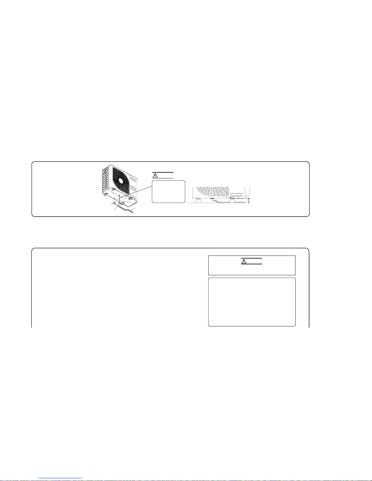
-
23
-
Wires for connecting indoor
and outdoor units
Exterior tape
Gas piping
Insulation
Liquid piping
Band (accessory)
Pipe cover (accessory)
Cable name plate
Power supply terminal block
○
It holds cables in place and protect the terminal
connection from external force.
○
This clamp is for the cable in the outside
diameter 9~15mm.
Please adjust it when not suitable.
○
Please be sure to carry out D-type (type III)
grounding work.
○
It has stuck on the lid of a control box.
Grounding terminal
Cable clamp
Indoor - Outdoor
connecting wire
Power cable
Please connect the earthed line of indoor and outdoor
connecting wire to a bracket part of the illustration
power cable, indoor - outdoor connecting wire circuit diagram
4. ELECTRICAL WIRING WORK
3. DRAIN PIPING WORK
●
When condensed water needs to be
led to a drain, etc., install the unit on
a flat base (supplied separately as an
optional part) or concrete blocks.
ޓThen, please secure space for the drain
elbow and the drain hose.
Drain elbow
Grommet
Drain hose
(To be procured on the installer's part)
7) Heating and condensation prevention
(1) Dress refrigerant pipes (both gas and liquid pipes) for heat insulation and prevention of dew condensation.
- Improper heat insulation/anti-dew dressing can result in a water leak or dripping causing damage to household effects, etc.
(2) Use a heat insulating material that can withstand 120℃ or a higher temperature. Poor heat insulating capacity can cause heat insulation problems or cable
deterioration.
- All gas pipes must be securely heat insulated in order to prevent damage from dripping water that comes from the condensation formed on them during a cooling operation
or personal injury from burns because their surface can reach quite a high temperature due to discharged gas flowing inside during a heating operation.
- Wrap indoor units’ flare joints with heat insulating parts (pipe cover) for heat insulation (both gas and liquid pipes).
- Give heat insulation to both gas and liquid side pipes. Bundle a heat insulating material and a pipe tightly together so that no gaps may be left between them and wrap them
together with a connecting cable by a dressing tape.
- Both gas and liquid pipes need to be dressed with 20 mm or thicker heat insulation materials above the ceiling where relative humidity exceeds 70%.
●
Execute drain piping by using a drain elbow and drain
grommets supplied separately as optional parts, where
water drained from the outdoor unit is a problem.
Where you are likely to have several days of sub-zero
temperatures in a row, do not use a drain elbow and
drain grom mets. (There is a risk of drain water
freezing inside and blocking the drain.)
Do not put a grommet
on this hole.
This is a supplementary
drain hole to discharg e
drain water, when a large
quantity of it is gathered.
Take care so that installed pipes may not touch
components within a unit.
If touching with an internal component
, it will generate abnormal sounds and/or vibrations.
4) On-site piping work
IMPORTANT
How to remove the side cover
●
Carry out the on site piping work with the operation valve fully closed.
●
Give sufficient protection to a pipe end (compressed and blazed, or with an adhesive tape) so
that water or foreign matters may not enter the piping.
●
Bend a pipe to a radius as large as practical.(R100〜R150) Do not bend a pipe repeatedly to correct
its form.
●
Flare connection is used between the unit and refrigerant pipe. Flare a pipe after engaging a
flare nut onto it. Flare dimensions for R410A are different from those for conventional R407C.
Although we recommend the use of flaring tools designed specifically for R410A, conventional
flaring tools can also be used by adjusting the measurement of protrusion B with a protrusion
control gauge.
●
Tighten a flare joint securely with a double spanner.
Please remove the screw of a side cover and remove to the front.
A
B
Flared pipe end : A (mm)
φ6.35
φ9.52
Copper
pipe outer
diameter
0
ー0.4
A
9.1
13.2
Copper pipe protrusion for flaring : B
(mm)
φ6.35
φ9.52
Copper
pipe outer
diameter
In the case of a rigid (clutch) type
With an R410A tool With a conventional tool
0〜0.5 1.0〜1.5
CAUTION
CAUTION
Do not apply force beyond proper fastening torque in tightening the flare nut.
Fix both liquid and gas service valves at the valve main bodies as illustrated on the right, and then fasten them,
applying appropriate fastening torque.
Tightening angle (°)
Tightening torque (N-m)
φ6.35 (1/4")
φ9.52 (3/8")
14〜18
34〜42
45〜60
30〜45
150
200
Use a torque wrench. If a torque wrench is
not available, fasten the flare nut manually
first and then tighten it further, using the
left table as a guide.
Recommended length of a tool handle (mm)Operation valve size (mm)
5) Air tightness test
① Although outdoor and indoor units themselves have been tested for air tightness at the factory, check the connecting pipes after the installation work for air tightness
from the operation valve’s check joint equipped on the outdoor unit side. While conducting a test, keep the operation valve shut all the time.
a) Raise the pressure to 0.5 MPa, and then stop. Leave it for five minutes to see if the pressure drops.
b) Then raise the pressure to 1.5 MPa, and stop. Leave it for five more minutes to see if the pressure drops.
c) Then raise the pressure to the specified level (4.15 MPa), and record the ambient temperature and the pressure.
d) If no pressure drop is observed with an installation pressurized to the specified level and left for about one day, it is acceptable. When the ambient Temperature fall
1℃, the pressure also fall approximately 0.01 MPa. The pressure, if changed, should be compensated for.
e) If a pressure drop is observed in checking e) and a) – d), a leak exists somewhere. Find a leak by applying bubble test liquid to welded parts and flare joints and
repair it. After repair, conduct an air-tightness test again.
② In conducting an air-tightness test, use nitrogen gas and pressurize the system with nitrogen gas from the gas side. Do not use a medium other than nitrogen gas
under any circumstances.
Gas side
operation valve
Check joint
Pressur
ize
Close
Outdoor unit
Indoor unit
<Work flow>
6) Evacuation
Pay attention to the following points in addition to the above for the R410A and
compatible machines.
○ To prevent a different oil from entering, assign dedicated tools, etc. to each refrigerant
type. Under no circumstances must a gauge manifold and a charge hose in particular
be shared with other refrigerant types (R22, R407C, etc.).
○
Use a counterflow prevention adapter to prevent vacuum pump oil from entering the
refrigerant system.
Airtighteness test completed
Fill refrigerant
Vacuum gauge check
Vacuuming completed
Vacuuming begins
Run the vacuum pump for at least one hour after the vacuum
gauge shows -101kPa or lower. (-755mmHg or lower)
Confirm that the vacuum gauge indicator does not rise even if
the system is left for one hour or more.
When the system has remaining moisture
inside or a leaky point, the vacuum gauge
indicator will rise.
Check the system for a leaky point and
then draw air to create a vacuum again.
INSTALLATION TEST CHECK POINTS
After installation
Check the following points again after completion of the installation, and before turnig on the power. Conduct a test run again and ensure that the unit operates properly.
Explain to the customer how to use the unit and how to take care of the unit following the instruction manual.
Screw
Side cover
Power cables and crossover wires are securely fixed to the terminal block.
The power supply voltage is correct as the rating.
The drain hose is fixed securely.
Operational valve is fully open.
No gas leaks from the joints of the operational valve.
Do not hold the valve cap area with a spanner.
Electrical installation work must be performed by an electrical installation service provider qualified by a power provider of the country.
Electrical installation work must be executed according to the technical standards and other regulations applicable to electrical installations in the country.
●
Do not use any supply cord lighter than one specified in parentheses for each type below.
- braided cord (code designation 60245 IEC 51),
- ordinary tough rubber sheathed cord (code designation 60245 IEC 53)
- flat twin tinsel cord (code designation 60227 IEC 41);
Use polychloroprene sheathed flexible cord (code designation 60245 IEC57) for supply cords of parts of appliances for outdoor use.
●
Ground the unit. Do not connect the grounding wire to a gas pipe, water pipe, lightning rod or telephone grounding wire
If impropery grounded, an electric shock or malfunction may result.
●
A grounding wire must be connected before connecting the power cable. Provide a grounding wire longer than the power cable.
●
The installation of an impulse withstanding type earth leakage breaker is necessary. A failure to install an earth leakage breaker can result in an
acccident such as an electric shock or a fire.
●
Do not turn on the power until the electrical work is completeted .
●
Do not use a condensive capacitor for power factor improvement under any circumstances. (It dose not improve power factor, while it can cause
an abnormal overheat accident)
●
For power supply cables, use conduits.
●
Do not layelectronic control cables (remote controland signaling wires) and other cablestogether outside the unit. Layingthem together can result
in the malfunctioning or a failure of the unit due to electric noises.
●
Fasten cables so that may not touch the piping, etc.
●
When cables are connected, make sure that all electrical components within the electrical component box are free of loose connector coupling or
terminal connection and then attach the cover securely. (Improper cover attachment can result in malfunctioning or a failure of the unit, if water
penetrates into the box.)
●
Always use a three-core cable for an indoor-outdoor connecting cable. Never use a shield cable.
Clearance
4. ELECTRICAL WIRING WORK
For details of electrical cabling, refer to the indoor unit installation manual.
RWC012A030
CAUTION
In case of faulty wiring connection, the indoor unit stops,
and then the run lamp turns on and the timer lamp blinks.
Use cables for interconnection wiring to avoid loosening of the wires.
CENELEC code for cables Required field cables.
H05
H
05
R
N
R
4or5
G
1.5
RNR3G1.5 (Example) or 245IEC57
Harmonized cable type
300/500 volts
Natural-and/or synth. rubber wire insulation
Polychloroprene rubber conductors insulation
Stranded core
Number of conductors
One conductor of the cable is the earth conductor
(yellow/green)
Section of copper wire (mm2)
Electrical installation work must be performed by an electrical installation service provider qualified by a power provider of the country.
Electrical installation work must be executed according to the technical standards and other regulations applicable to electrical installations in the country.
●
Do not use any supply cord lighter than one specified in parentheses for each type below.
- braided cord (code designation 60245 IEC 51),
- ordinary tough rubber sheathed cord (code designation 60245 IEC 53)
- flat twin tinsel cord (code designation 60227 IEC 41);
Use polychloroprene sheathed flexible cord (code designation 60245 IEC57) for supply cords of parts of appliances for outdoor use.
●
Ground the unit. Do not connect the grounding wire to a gas pipe, water pipe, lightning rod or telephone grounding wire
.
If impropery grounded, an electric shock or malfunction may result.
●
A grounding wire must be connected before connecting the power cable. Provide a grounding wire longer than the power cable.
●
The installation of an impulse withstanding type earth leakage breaker is necessary. A failure to install an earth leakage breaker can result in an
acccident such as an electric shock or a fire.
●
Do not turn on the power until the electrical work is completeted .
●
Do not use a condensive capacitor for power factor improvement under any circumstances. (It dose not improve power factor, while it can cause
an abnormal overheat accident)
●
For power supply cables, use conduits.
●
Do not layelectronic control cables (remote controland signaling wires) and other cablestogether outside the unit. Layingthem together can result
in the malfunctioning or a failure of the unit due to electric noises.
●
Fasten cables so that may not touch the piping, etc.
●
When cables are connected, make sure that all electrical components within the electrical component box are free of loose connector coupling or
terminal connection and then attach the cover securely. (Improper cover attachment can result in malfunctioning or a failure of the unit, if water
penetrates into the box.)
●
Always use a three-core cable for an indoor-outdoor connecting cable. Never use a shield cable.
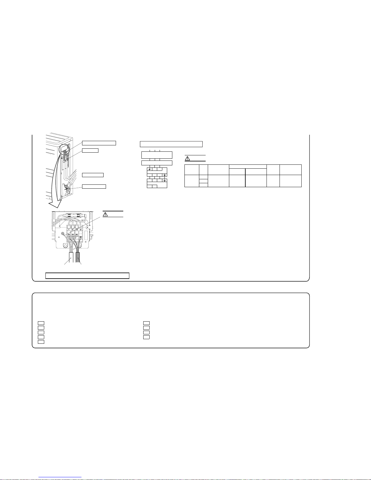
‑
24
*
‑
Cable name plate
Power supply terminal block
○
It holds cables in place and protect the terminal
connection from external force.
○
This clamp is for the cable in the outside
diameter 9~15mm.
Please adjust it when not suitable.
○
Please be sure to carry out D-type (type III)
grounding work.
○
It has stuck on the lid of a control box.
Grounding terminal
Cable clamp
Indoor - Outdoor
connecting wire
Power cable
Please connect the earthed line of indoor and outdoor
connecting wire to a bracket part of the illustration.
power cable, indoor - outdoor connecting wire circuit diagram
CAUTION
CAUTION
Power cable, indoor-outdoor connecting wires
Always use an earth leakage circuit breaker designed for inverter circuits to
prevent a faulty operation.
●
Always perform grounding system installation work with the power cord unplugged.
L
Outdoor unit
Switchgear or Circuit breaker
N
1 2/N 3
1 2/N 3
Indoor unit
XY
Earth leakage breaker
(Harmonic resistant type)
Interconnecting and
grounding wires
(minimum)
20
25
35
2.0
mm
2
30A 16A
1.5
mm
2
×4
15A,30mA,
0.1sec or less
Switchgear or Circuit Breaker
Switch breaker
Over current protector
rated capacity
Earth leakage breaker
●
The specifications show in the above table are for units without heaters. For units with heaters,refer to
the installation instructions or the construction instructions of the indoor unit.
●
Switchgear or Circuit breaker capacity which is calculated from MAX. over current should be chosen along the
regulations in each country.
●
The cable specifications are based on the assumption that a metal or plastic conduit is used with no more than
three cables contained in a conduit and a voltage drop is 2%. For an installation falling outside of these
conditions, please follow the internal cabling regulations. Adapt it to the regulation in effect in each country.
Power souce
(minimum)
ModelPhase
Single-phase
INSTALLATION TEST CHECK POINTS
After installation
Check the following points again after completion of the installation, and before turnig on the power. Conduct a test run again and ensure that the unit operates properly.
Explain to the customer how to use the unit and how to take care of the unit following the instruction manual.
Power cables and crossover wires are securely fixed to thet erminal block.
The power supply voltage is correct as the rating.
The drain hose is fixed securely.
Operational valve is fully open.
No gas leaks from the joints of the operation alvalve.
The pipe joints for indoor and outdoor pipes have been insulated.
The reverse flow check cap is attached.
The cover of the pipe cover (A) faces downward to prevent rain from entering.
Gaps are properly sealed between the pipe covers (A) (B) and the wall surface / pipes.
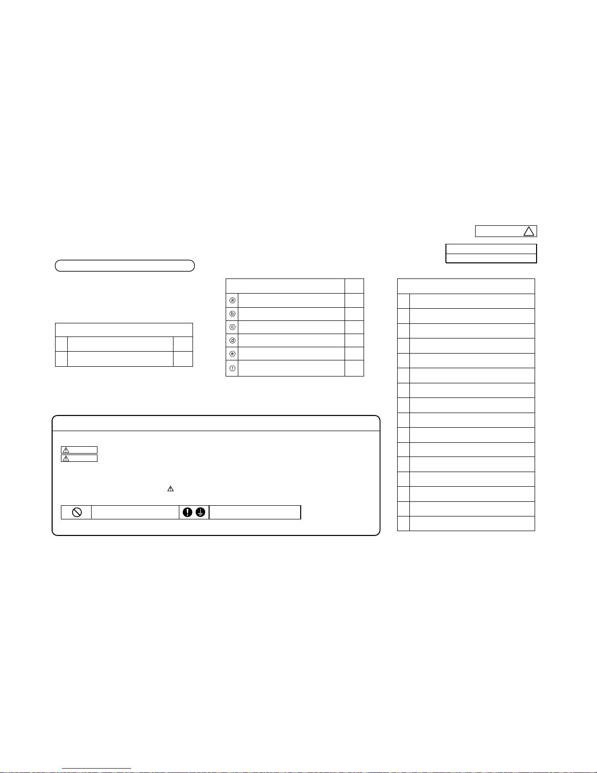
*
Models SRC50ZIX-S, 60ZIX-S
PRECAUTIONS FOR SAFETY
◎
This installation manual deals with outdoor units and general installation specifications only. For indoor units, refer to the respective
installation manuals supplied with the units.
◎
Read this manual carefully before you set to installation work and carry it out according to the instruction scontained in this manual.
●
When installing the equipment, carefully read the Precautions for safety and make sure that safety is maintained.
●
The safety items contain important information regarding safety. Be sure to follow them. The symbols used and their meanings are as follows.
WARNING
: Improper installation could result in serious accident causing death, serious injury or environmental pollution.
CAUTION
: Improper installation could result in serious accident.
●
After installation, along with confirming that no abnormalities were seen from the operation test. Explain operating methods as well as maintenance
methods to the user of this equipment, based on the owner’s manual.
●
Ask the customer to keep this manual together with the operation manual.
●
In installing the unit, you must also take thorough safety precautions to protect your person.
A failure to observe any safety instruction listed under “ Caution” can also result in aserious consequence depending on the circumstances.
Please observe all these instructions, because they include important points concerning safety.
●
The meanings of “Marks” used here are as follows:
●
Beware of danger from a dropped tool or the like in installing the unit in an elevated position.
●
When the air conditioning unit makes abnormal sounds in operation, consult with your dealer.
Never do it under any circumstances. Always do it according to the instruction.
Check before installation work
●
Model name and power source
●
Refrigerant piping length
●
Piping,wiring and miscellaneous small parts
●
Indoor unit installation manual
①
②
4
1
Accessories for outdoor unit
Gromet (Heat pump type only)
Drain elbow (Heat pump type only)
1
1
1
1
1
1
Q’ty
Option parts
Sealing plate
Sleeve
Inclination plate
Putty
Drain hose (extention hose)
Piping cover
(for insulation of connection piping)
Necessary tools for the installation work
1
2
3
4
5
6
7
8
9
10
11
12
13
14
15
16
Plus headed driver
Knife
Saw
Tape measure
Hammer
Spanner wrench (14.0〜 62.0N・m (1.4 〜 6.2kgf・m))
Torque wrench
Hole core drill (65mm in diameter)
Wrench key (Hexagon) [ 4 m/m]
Vacuum pump
Vacuum pump adapter
(Anti-reverse flow type)
Gauge manifold(Designed specifically for R410A)
Charge hose(Designed specifically for R410A)
Flaring tool set(Designed specifically for R410A)
Gas leak detector(Designed specifically for R410A)
Gauge for projection adjustment
(Used when flare is made by using conventional flare tool)
(Designed specifically for R410A)
Model 40・50・60
Designed for R410A refrigerant
RWC012A029
b
-
25
-
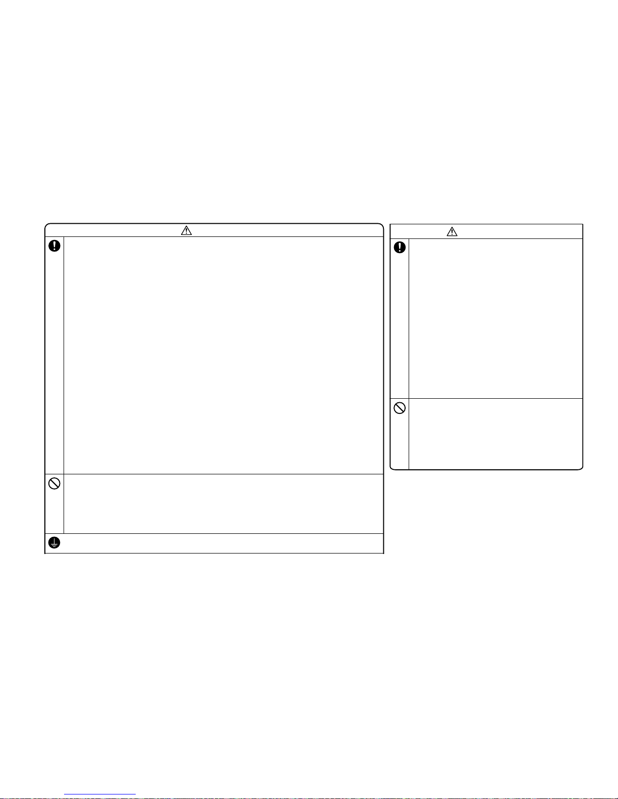
-
26
-
2. REFRIGERANT PIPING WORK
1) Restrictions on unit installation and use
●Check the following points in light of the indoor unit specifications and the installation site.
●Observe the following restrictions on unit installation and use. Improper installation can result in a compressor failure or performance degradation
30m or less
20m or less
20m or less
PRECAUTIONS FOR SAFETY
RWC012A029
Model 40・50・60
Designed for R410A refrigerant
●
To disc onnect the a ppliance from the mains s upply this ap pliance must be connected to the main s by means of a circuit b reaker or a switc h
(use a recognized 16A) with a contact separation of at least 3mm.
●
The appliance shall be installed in accordance with national wiring regulations.
●
This system should be applied to places as households, residences and the like. Application to inferior environment such as engineering shop
could cause equipment malfunction.
●
Ask your dealer or a specialized service provider to install the unit.
Improper installation work performed on the part of a user can result in a water leak, electric shock or fire.
●
Carry out installation work properly according to this installation manual.
Improper installation work can result in a water leak, electric shock, or fire.
●
Always turn off power before you work inside the unit such as for installation or servicing.
A failure to observe this instruction can result in an electric shock.
●
Install the unit securely onto a structure that is strong enough to sustain its weight.
Insufficient strength or improper installation can cause a fall of the unit and resultant injury.
●
Electrical installation work must be performed according to the installation manual as dedicated circuits exclusively for the air conditioning system in
compliance with the applicable “Technical standards for electrical installation” and “Indoor wiring regulations.”
A defect in power supply circuits such as insufficient capacity or improper installation can cause an electrical shock or fire.
●
Always connect between indoor and outdoor units securely with specified cables. Never use an intermediate connection or stranded wire for this purpose.
Fasten cables securely so that the terminal block may not be subject to external force working through cables.
Improper connection or fastening can cause heat generation and a resultant fire.
●
Neatly arrange the cables connecting between indoor and outdoor units so that they may not get loose, and put on the lid and/or service panel securely.
Improper installation can cause heat generation at terminal connections and a resultant fire or electric shock.
●
Use only parts supplied with the unit and approved supply parts for installation work.
A failure to use genuine parts approved by the manufacturer may result in a fall of the unit, a water leak, a fire, an electric shock, a refrigerant leak, substandard performance or a control failure.
●
If refrigerant gas leaks during installation work, ventilate the room.
Refrigerant gas, if it comes into contact with bare fire, can cause the generation of a toxic gas.
●
Use pipes, flare nuts and tools specifically designed for R410A.
The diversion of existing materials (designed for R22) can result in a unit failure as well as a serious accident such as refrigeration cycle rupture or injury.
●
In carrying out a pump-down process, stop the compressor before you detach the refrigerant pipe.
If you detach the pipe with the compressor running and the operation valves (liquid and gas sides) open, an abnormal pressure build-up will occur in the refrigeration cycle, which
can result in pipe rupture or injury.
●
In installing the unit, be sure to attach the refrigerant pipe before operating the compressor.
If you run the compressor without attaching the refrigerant pipe and with the operation valves (liquid and gas sides) open, you may incur frost bite or injury from an abrupt
refrigerant outflow. An abnormal pressure build-up may also occur in the refrigeration cycle as a result of the inhalation of air, which can result in pipe rupture or injury.
●
Tighten a flare nut with a torque wrench in a specified manner.
Over-tightening a flare nut can cause a refrigerant gas leak from breakage after years of operation and the generation of a toxic product, if refrigerant gas comes into contact with bare fire.
●
In inserting the power cable plug, make sure that no anomalies such as dust deposits, socket clogging or wobble are found in both the plug and outlet and
insert the plug fully to the roots of its blades.
Dust deposits, clogging or wobble can result in an electric shock or fire. If the outlet is loose, change it with a new one.
●
Never open the operation valves (either liquid or gas side) until refrigerant pipe installation work, an air-tightness test and an air purge are completed.
A failure to observe this instruction can result in frost bite or injury from an abrupt refrigerant outflow. If refrigerant gas leaks during installation work, immediately stop pipe
blazing and other work and ventilate the room.
●
Do not run the drain piping directly into the sewer where a toxic gas such as sulfuric gas is generated.
This will pose a risk of a toxic gas flowing back into the room. This can also cause the corrosion of the indoor unit and a resultant unit failure or refrigerant leak.
●
You must collect, bring back and shred or otherwise properly dispose of all packaging materials, expanded polystyrene, bands, vinyl bags and so on used for
the transpiration of the indoor and outdoor units after installation work.
●
In installing or transferring an air conditioning system, never allow air or other foreign matters than specified refrigerant (R410A) to get into the refrigerant cycle (piping).
If air or other foreign matters gets into the refrigerant cycle, an abnormal pressure build-up will occur, which can result in pipe rupture or injury.
●
Never modify the power cord, introduce an intermediate connection or connect it in a daisy chain.
A failure to observe this instruction can result in a fire or electric shock from improper contact, improper insulation, excessive current beyond rating, etc.
●
Never bundle, wind or modify the power cord. Do not step onto the power plug or otherwise deform it.
A failure to observe this instruction can result in heat generation or ignition.
●
Ensure that the unit is properly grounded.
Do not connect the grounding wire to a gas pipe, water pipe, lightning rod, or telephone ground wire.
If a defect is in a ground, it will become a cause of an electric shock at the time of failure or a short circuit.
Notabilia as a unit designed for R410A
●
Do not use any refrigerant other than R410A. R410A will rise to pressure about 1.6 times higher than that of a conventional refrigerant.
A cylinder containing R410A has a pink indication mark on the top.
●
A unit designed for R410A has adopted a different size indoor unit operation valve charge port and a different size check joint provided in the unit to prevent the charging of a wrong refrigerant by mistake.
The processed dimension of the flared part of a refrigerant pipe and a flare nut's parallel side measurement have also been altered to raise strength against pressure.
Accordingly, you are required to arrange dedicated R410A tools listed in the table on the right before installing or servicing this unit.
●
Do not use a charge cylinder. The use of a charge cylinder will cause the refrigerant composition to change, which results in performance degradation.
●
In charging refrigerant, always take it out from a cylinder in the liquid phase.
●
All indoor units must be models designed exclusively for R410A. Check connectable indoor unit models in a catalog, etc. (A wrong indoor unit, if connected into the system, will impair proper system operation)
◎This installation manual deals with outdoor units and general installation specifications only. For indoor units, refer to the respective
installation manuals supplied with the units.
◎Read this manual carefully before you set to installation work and carry it out according to the instructions contained in this manual.
●
When installing the equipment, carefully read the Precautions for safety and make sure that safety is maintained.
●
The safety items contain important information regarding safety. Be sure to follow them. The symbols used and their meanings are as follows.
WARNING
: Improper installation could result in serious accident causing death, serious injury or environmental pollution.
CAUTION
: Improper installation could result in serious accident.
●
After installation, along with confirming that no abnormalities were seen from the operation test. Explain operating methods as well as maintenance
methods to the user of this equipment, based on the owner’s manual.
●
Ask the customer to keep this manual together with the operation manual.
●
In installing the unit, you must also take thorough safety precautions to protect your person.
A failure to observe any safety instruction listed under “ Caution” can also result in a serious consequence depending on the circumstances.
Please observe all these instructions, because they include important points concerning safety.
●
The meanings of “Marks” used here are as follows:
●
Beware of danger from a dropped tool or the like in installing the unit in an elevated position.
●
When the air conditioning unit makes abnormal sounds in operation, consult with your dealer.
1. HAULAGE AND INSTALLATION
(Take particular care in carrying in or moving the unit, and always perform such an operation with two or more persons.)
CAUTION
When a unit is hoisted with slings for haulage, take into consideration the offset of its gravity center position.
If not properly balanced, the unit can be thrown off-balance and fall.
1) Delivery
●
Deliver the unit as close as possible to the installation site before removing it from
the packaging.
●
When you have to unpack the unit for a compelling reason before you haul it to the
installation point, hoist the unit with nylon slings or ropes and protection pads so that
you may not damage the unit.
2) Portage
●
The right hand side of the unit as viewed from the front (diffuser side) is heavier.
A person carrying the right hand side must take heed of this fact. A person carrying
the left hand side must hold with his right hand the handle provided on the front panel
of the unit and with his left hand the corner column section
.
3) Selecting the installation location
Be careful of the following conditions and choose an installation place.
〇
Where air is not trapped.
〇
Where the installation fittings can be firmly installed.
〇
Where wind does not hinder the intake and outlet pipes.
〇
Out of the heat range of other heat sources.
〇
A place where stringent regulation of electric noises is applicable.
〇 Where it is safe for the drain water to be discharged.
〇
Where noise and hot air will not bother neighboring residents.
〇
Where snow will not accumulate.
〇
Where strong winds will not blow against the outlet pipe.
〇
A place where no TV set or radio receiver is placed within 5m.
(If electrical interference is caused, seek a place less likely to cause the problem)
〇
If a operation is conducted when the outdoor air temperature is -5℃lower, the outdoor unit should be installed
at a place where it is not influenced by natural wind.
〇
Where it is likely that the unit is subjected to strong winds, provide wind guards according to the following guidelines
.
Strong winds can cause performance degradation, an accidental stop due to a rise of high pressure and a broken fan
.
1.Place the unit outlet pipe perpendicular to the wind direction.
Heavy
Wind direction
Wind direction
2.Install so the direction of the air from the blowing outlet will be
perpendicular to the direction of the wind.
CAUTION
●
The use restrictions appearing in the table above are applicable to the standard pipe size combinations shown in the table below.
Where an existing pipe system is utilized, different one-way pipe length restrictions should apply depending on its pipe size.
For more information, please see “
5. UTILIZATION OF EXISTING PIPING.
”
Restrictions
Dimensional restrictions
Marks appearing in the drawing on the right
Main pipe length
When the outdoor unit is positioned higher,
When the outdoor unit is positioned lower,
Elevation difference between
indoor and outdoor units
Pad
Never do it under any circumstances. Always do it according to the instruction.
WARNING
Over 500mm
●
Take sufficient care so that you may not incur injury from heat exchanger fins,
pipe flares and screws during work.
●
Install drain piping according to the installation manual to ensure good drainage,
and give it heat insulation to prevent condensation.
Improper installation can result in a flood of water in the room and soaked household effects.
●
When the unit is installed in a humid or damp place, the installation of an earth
leakage breaker is essential.
A failure to install an earth leakage breaker can cause an electric shock.
●
When the air conditioning system is installed in a room equipped with a ventilating
fan and it is used (for a cooling or dehumidifying operation) simultaneously
with the ventilating fan, the room may have a negative air pressure relative to the
exterior, which can cause a reverse flow of drain water. Make sure that the room
has an opening that allows the inflow of as much air as discharged by the
ventilation fan. (For example, open the door a little) Similarly, provide an adequate
opening, if a room has a negative air pressure relative to the exterior due to the effect
of winds in a high-rise condominium building or the like.
●
Secure a service space for inspection and maintenance as specified in the manual.
An insufficient service space can result in a fall from the installation point and resultant injury.
●
When the outdoor unit is installed on a roof top or in an elevated position,
provide permanent ladders and handrails along the access path and fences or
handrails surrounding the outdoor unit.
●
Dress the refrigerant piping with a heat insulation material to prevent condensation.
Improper heat insulation given to refrigerant piping for condensation prevention can result in
leaking or dripping water soaking household effects.
●
In removing packaging materials, take sufficient care so as not to damage the
contents or incur injury from such work.
●
Do not install the unit in the place where a risk of inflammable gas leaks exists.
Should gas leak and gather around the unit, it can cause the ignition of gas.
●
Do not touch the air intake and aluminum fins of the outdoor unit.
You may incur injury if you touch them.
●
Do not install the outdoor unit in a place where small animals are likely to inhabit.
If they enter the unit and touch electrical parts inside, they may cause a unit failure or fire.
Please ask the customer to keep the surroundings clean.
●
Do not install the outdoor unit where its fan winds directly hit a plant etc.
Fan winds can affect adversely to the plant etc.
●
Do not operate the outdoor unit with any article placed on it.
A failure to observe this instruction can result in a fall of the article and resultant property
damage or personal injury.
CAUTION
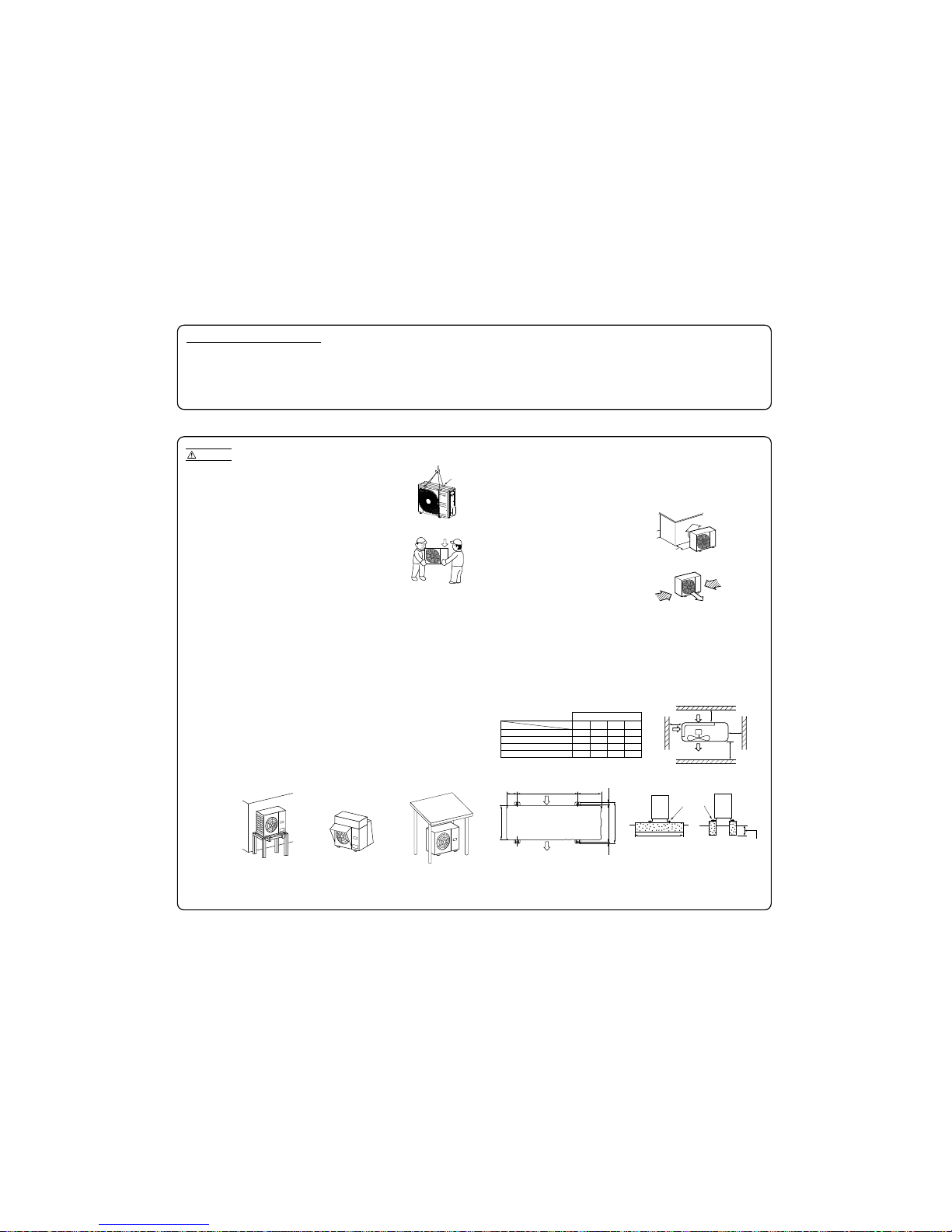
-
27
-
Notabilia as a unit designed for R410A
●
Do not use any refrigerant other than R410A. R410A will rise to pressure about 1.6 times higher than that of a conventional refrigerant.
A cylinder containing R410A has a pink indication mark on the top.
●
A unit designed for R410A has adopted a different size indoor unit operation valve charge port and a different size check joint provided in the unit to prevent the charging of a wrong refrigerant by mistake.
The processed dimension of the flared part of a refrigerant pipe and a flare nut's parallel side measurement have also been altered to raise strength against pressure.
Accordingly, you are required to arrange dedicated R410A tools listed in the table on the right before installing or servicing this unit.
●
Do not use a charge cylinder. The use of a charge cylinder will cause the refrigerant composition to change, which results in performance degradation.
●
In charging refrigerant, always take it out from a cylinder in the liquid phase.
●
All indoor units must be models designed exclusively for R410A. Check connectable indoor unit models in a catalog, etc. (A wrong indoor unit, if connected into the system, will impair proper system operation)
1. HAULAGE AND INSTALLATION
(Take particular care in carrying in or moving the unit, and always perform such an operation with two or more persons.)
②
Notabilia for installation
Intake
The height of a wall is 1200mm or less.
(
service
space
)
Intake
Outlet
Fasten with bolts
(M10-12)
Use a thicker block to anchor deeper.
Use a long block to
extend the width.
CAUTION
When a unit is hoisted with slings for haulage, take into consideration the offset of its gravity
center position. If not properly balanced, the unit can be thrown off-balance and fall.
1) Delivery
●
Deliver the unit as close as possible to the installation site before removing it from
the packaging.
●
When you have to unpack the unit for a compelling reason before you haul it to the
installation point, hoist the unit with nylon slings or ropes and protection pads so that
you may not damage the unit.
2) Portage
●
The right hand side of the unit as viewed from the front (diffuser side) is heavier.
A person carrying the right hand side must take heed of this fact. A person carrying
the left hand side must hold with his right hand the handle provided on the front panel
of the unit and with his left hand the corner column section
.
3) Selection of installation location for the outdoor unit
Be sure to select a suitable installation place in consideration of following conditions.
〇 A place where it is horizontal, stable and can endure the unit weight and will not allow vibration transmittance
of the unit.
〇 A place where it can be free from possibility of bothering neighbors due to noise or exhaust air from the unit.
〇 A place where the unit is not exposed to oil splashes.
〇 A place where it can be free from danger of flammable gas leakage.
〇 A place where drain water can be disposed without any trouble.
〇 A place where the unit will not be affected by heat radiation from other heat source.
〇 A place where snow will not accumulate.
〇 A place where the unit can be kept away 5m or more from TV set and/or radio receiver in order to avoid any
radio or TV interference.
〇 A place where good air circulation can be secured, and enough service space can be secured for maintenance
and service of the unit safely.
〇 A place where the unit will not be affected by electromagnetic waves and/or high-harmonic waves generated by
other equipment.
〇 A place where chemical substances like sulfuric gas, chloric gas, acid and alkali (including ammonia), which can
harm the unit, will not be generated and not remain.
〇 If a operation is conducted when the outdoor air temperature is -5 lower, the outdoor unit should be installed
at a place where it is not influenced by natural wind.
〇 A place where strong wind will not blow against the outlet air blow of the unit.
5) Installation space
●
Walls surrounding the unit in the four sides are not acceptable.
●
There must be a 1-meter or larger space in the above.
●
When more than one unit are installed side by side, provide a 250mm or wider interval between them as a service
space. In order to facilitate servicing of controllers, please provide a sufficient space between units so that their
top plates can be removed easily.
●
Where a danger of short-circuiting exists, install guide louvers.
●
When more than one unit are installed, provide sufficient intake space consciously so that short-circuiting may not occur
.
●
Where piling snow can bury the outdoor unit, provide proper snow guards.
L3
L2
L4
L1
Model 40, 50, 60
Example installation
Size
L1
L2
L3
L4
Ⅰ
Open
100
100
250
Ⅱ
280
75
80
Open
Ⅲ
280
Open
80
250
Ⅳ
180
Open
80
Open
(mm)
①
Anchor bolt fixed position
●
In installing the unit, fix the unit’s legs with bolts specified on the left.
●
The protrusion of an anchor bolt on the front side must be kept within 15 mm.
●
Securely install the unit so that it does not fall over during earthquakes or strong winds, etc.
●
Refer to the above illustrations for information regarding concrete foundations.
●
Install the unit in a level area. (With a gradient of 5 mm or less.)
Improper installation can result in a compressor failure, broken piping within the unit and abnormal noise generation.
Heavy
6) Installation
Pad
Intake
Outlet
312.5
24.314.8
288.7
88.4
510 200
351.6
4) Caution about selection of installation location
(1) If the unit is installed in the area where the snow will accumulate, following measures are required.
The bottom plate of unit and intake, outlet may be blocked by snow.
Install the unit on the base so
that the bottom is higher than
snow cover surface.
Provide a snow hood to
the outdoor unit on site.
Install the unit under eaves
or provide the roof on site.
(2) If the unit can be affected by strong wind, following measures are required.
Strong wind can cause damage of fan (fan motor), or can cause performance degradation, or can trigger
anomalous stop of the unit due to rising of high pressure.
Since drain water generated by defrost control may freeze, following measures are required.
●
Don’t execute drain piping work by using a drain elbow and drain grommets (optional parts). [Refer to Drain
piping work.]
●
Recommend setting Defrost Control (SW3-1) and Snow Guard Fan Control (SW3-2). [Refer to Setting SW3-1,
SW3-2.]
1.Install the outlet air blow side of the unit to face a
wall of building, or provide a fence or a windbreak screen.
Wind direction
Wind direction
2.Install the outlet air blow side of the unit in a position
perpendicular to the direction of wind.
Over 500mm
Regarding outline of a snow
hood, refer to our technical
manual.
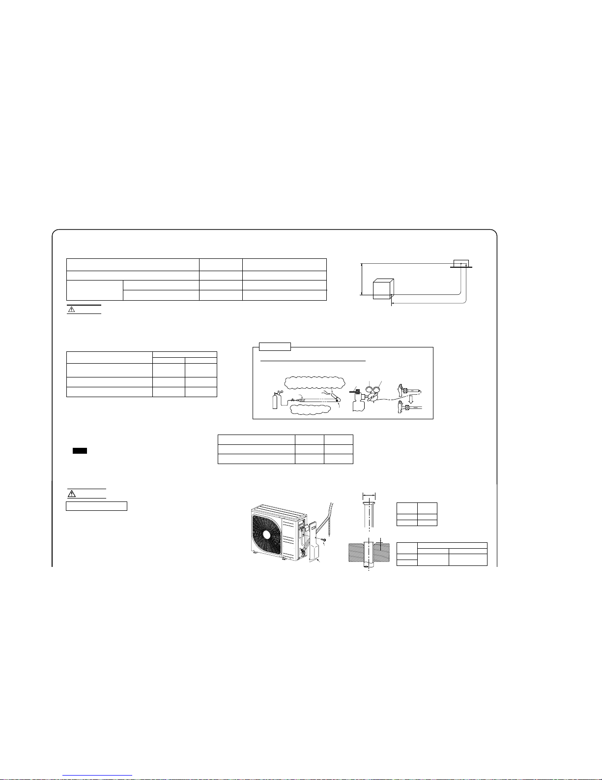
-
28
-
2. REFRIGERANT PIPING WORK
1) Restrictions on unit installation and use
●Check the following points in light of the indoor unit specifications and the installation site.
●Observe the following restrictions on unit installation and use. Improper installation can result in a compressor failure or performance degradation
.
2) Determination of pipe size
●Determine refrigerant pipe size pursuant to the following guidelines based on the
indoor unit specifications.
30m or less
20m or less
20m or less
L
H
H
Gas pipe
Liquid pipe
φ12.7 φ6.35
Flare Flare
φ12.7 φ6.35
φ12.7 φ6.35
Notabilia as a unit designed for R410A
●
Do not use any refrigerant other than R410A. R410A will rise to pressure about 1.6 times higher than that of a conventional refrigerant.
A cylinder containing R410A has a pink indication mark on the top.
●
A unit designed for R410A has adopted a different size indoor unit operation valve charge port and a different size check joint provided in the unit to prevent the charging of a wrong refrigerant by mistake.
The processed dimension of the flared part of a refrigerant pipe and a flare nut's parallel side measurement have also been altered to raise strength against pressure.
Accordingly, you are required to arrange dedicated R410A tools listed in the table on the right before installing or servicing this unit.
●
Do not use a charge cylinder. The use of a charge cylinder will cause the refrigerant composition to change, which results in performance degradation.
●
In charging refrigerant, always take it out from a cylinder in the liquid phase.
●
All indoor units must be models designed exclusively for R410A. Check connectable indoor unit models in a catalog, etc. (A wrong indoor unit, if connected into the system, will impair proper system operation)
1. HAULAGE AND INSTALLATION
(Take particular care in carrying in or moving the unit, and always perform such an operation with two or more persons.)
②
Notabilia for installation
Intake
The height of a wall is 1200mm or less.
(
service
space
)
Intake
Outlet
Fasten with bolts
(M10-12)
Use a thicker block toanchor deeper.
Use a long block to
extend the width.
CAUTION
When a unit is hoisted with slings for haulage, take into consideration the offset of its gravity center position.
If not properly balanced, the unit can be thrown off-balance and fall.
1) Delivery
●
Deliver the unit as close as possible to the installation site before removing it from
the packaging.
●
When you have to unpack the unit for a compelling reason before you haul it to the
installation point, hoist the unit with nylon slings or ropes and protection pads so that
you may not damage the unit.
2) Portage
●
The right hand side of the unit as viewed from the front (diffuser side) is heavier.
A person carrying the right hand side must take heed of this fact. A person carrying
the left hand side must hold with his right hand the handle provided on the front panel
of the unit and with his left hand the corner column section
.
3) Selecting the installation location
Be careful of the following conditions and choose an installation place.
〇
Where air is not trapped.
〇
Where the installation fittings can be firmly installed.
〇
Where wind does not hinder the intake and outlet pipes.
〇
Out of the heat range of other heat sources.
〇
A place where stringent regulation of electric noises is applicable.
〇
Where it is safe for the drain water to be discharged.
〇 Where noise and hot air will not bother neighboring residents.
〇
Where snow will not accumulate.
〇
Where strong winds will not blow against the outlet pipe.
〇 A place where no TV set or radio receiver is placed within 5m.
(If electrical interference is caused, seek a place less likely to cause the problem)
〇 If a operation is conducted when the outdoor air temperature is -5℃lower, the outdoor unit should be installed
at a place where it is not influenced by natural wind.
〇
Where it is likely that the unit is subjected to strong winds, provide wind guards according to the following guidelines
.
Strong winds can cause performance degradation, an accidental stop due to a rise of high pressure and a broken fan
.
4) Installation space
●
Walls surrounding the unit in the four sides are not acceptable.
●
There must be a 1-meter or larger space in the above.
●
When more than one unit are installed side by side, provide a 250mm or wider interval between them as a
service space. In order to facilitate servicing of controllers, please provide a sufficient space between units
so that their top plates can be removed easily.
●
Where a danger of short-circuiting exists, install guide louvers.
●
When more than one unit are installed, provide sufficient intake space consciously so that short-circuiting may not occur
.
●
Where piling snow can bury the outdoor unit, provide proper snow guards.
1.Place the unit outlet pipe perpendicular to the wind direction.
L
3
L2
L4
L1
Model 40, 50, 60
Example installation
Size
L1
L2
L3
L4
Ⅰ
Open
100
100
250
Ⅱ
280
75
80
Open
Ⅲ
280
Open
80
250
Ⅳ
180
Open
80
Open
(mm)
①
Anchor bolt fixed position
●
In installing the unit, fix the unit’s legs with bolts specified on the left.
●
The protrusion of an anchor bolt on the front side must be kept within 15 mm.
●
Securely install the unit so that it does not fall over during earthquakes or strong winds, etc.
●
Refer to the above illustrations for information regarding concrete foundations.
●
Install the unit in a level area. (With a gradient of 5 mm or less.)
Improper installation can result in a compressor failure, broken piping within the unit and abnormal noise generation.
Heavy
Wind direction
Wind direction
2.Install so the direction of the air from the blowing outlet will be
perpendicular to the direction of the wind.
5) Installation
L
H
Outdoor unit
Indoor unit
CAUTION
●
The use restrictions appearing in the table above are applicable to the standard pipe size combinations shown in the table below.
Where an existing pipe system is utilized, different one-way pipe length restrictions should apply depending on its pipe size.
For more information, please see “
5. UTILIZATION OF EXISTING PIPING.
”
Restrictions
Dimensional restrictions
Marks appearing in the drawing on the right
Main pipe length
When the outdoor unit is positioned higher,
When the outdoor unit is positioned lower,
Elevation difference between
indoor and outdoor units
Outdoor unit connected
Refrigerant piping (branch pipeL)
Indoor unit connected
Plug the end of the pipe with tape, or other
material, and fill the pipe with nitrogen gas.
Only use nitrogen gas (N2)
Taping
<N2>
Nitrogen
Brazing
Station valve
Primary side Secondary side
0.5MPa
Hand
Relief valve
Nitrogen
gas
Brazing must be performed under a nitrogen gas flow.
Without nitrogen gas, a large quantity of foreign matters (oxidized film) are created,
causing a critical failure from capillary tube or expansion valve clogging.
About brazing
When pipe is brazing.
3) Refrigerant pipe wall thickness and material
●
Select refrigerant pipes of the table shown on the right wall thickness and
material as specified for each pipe size.
Pipe diameter [mm]
Minimum pipe wall thickness [mm]
Pipe material*
6.35
0.8
O-type pipe
12.7
0.8
O-type pipe
NOTE
*Phosphorus deoxidized seamless copper pipe ICS 23.040.15, ICS 77.150.30
●
Select pipes having a wall thickness larger than the specified
minimum pipe thickness.
Pad
Over 500mm
Model 40, 50, 60
Intake
Outlet
312.5
24.314.8
288.7
88.4
510 200
351.6
4. ELECTRICAL WIRING WORK For details of electrical cabling, refer to the indoor unit installation manual.
Electrical installation work must be performed by an electrical installation service provider qualified by a power provider of the country.
Electrical installation work must be executed according to the technical standards and other regulations applicable to electrical installations in the country.
●
Do not use any supply cord lighter than one specified in parentheses for each type below.
- braided cord (code designation 60245 IEC 51),
- ordinary tough rubber sheathed cord (code designation 60245 IEC 53)
- flat twin tinsel cord (code designation 60227 IEC 41);
Use polychloroprene sheathed flexible cord (code designation 60245 IEC57) for supply cords of parts of appliances for outdoor use.
●
Ground the unit. Do not connect the grounding wire to a gas pipe, water pipe, lightning rod or telephone grounding wire
If impropery grounded, an electric shock or malfunction may result.
●
A grounding wire must be connected before connecting the power cable. Provide a grounding wire longer than the power cable.
●
The installation of an impulse withstanding type earth leakage breaker is necessary. A failure to install an earth leakage breaker can result in an
acccident such as an electric shock or a fire.
●
Do not turn on the power until the electrical work is completeted .
●
Do not use a condensive capacitor for power factor improvement under any circumstances. (It dose not improve power factor, while it can cause
Take care so that installed pipes may not touch
components within a unit.
If touching with an internal component
, it will generate abnormal sounds and/or vibrations.
4) On-site piping work
IMPORTANT
How to remove the side cover
●
Carry out the on site piping work with the operation valve fully closed.
●
Give sufficient protection to a pipe end (compressed and blazed, or with an adhesive tape) so
that water or foreign matters may not enter the piping.
●
Bend a pipe to a radius as large as practical.(R100〜R150) Do not bend a pipe repeatedly to correct
its form.
●
Flare connection is used between the unit and refrigerant pipe. Flare a pipe after engaging a
flare nut onto it. Flare dimensions for R410A are different from those for conventional R407C.
Although we recommend the use of flaring tools designed specifically for R410A, conventional
flaring tools can also be used by adjusting the measurement of protrusion B with a protrusion
control gauge.
●
Tighten a flare joint securely with a double spanner.
Please remove the screw of a side cover and remove to the front.
A
B
Flared pipe end : A (mm)
φ6.35
φ12.7
Copper
pipe outer
diameter
0
ー0.4
A
9.1
16.6
Copper pipe protrusion for flaring : B
(mm)
φ6.35
φ12.7
Copper
pipe outer
diameter
In the case of a rigid (clutch) type
With an R410A tool With a conventional tool
0〜0.5 1.0〜1.5
Screw
Side cover
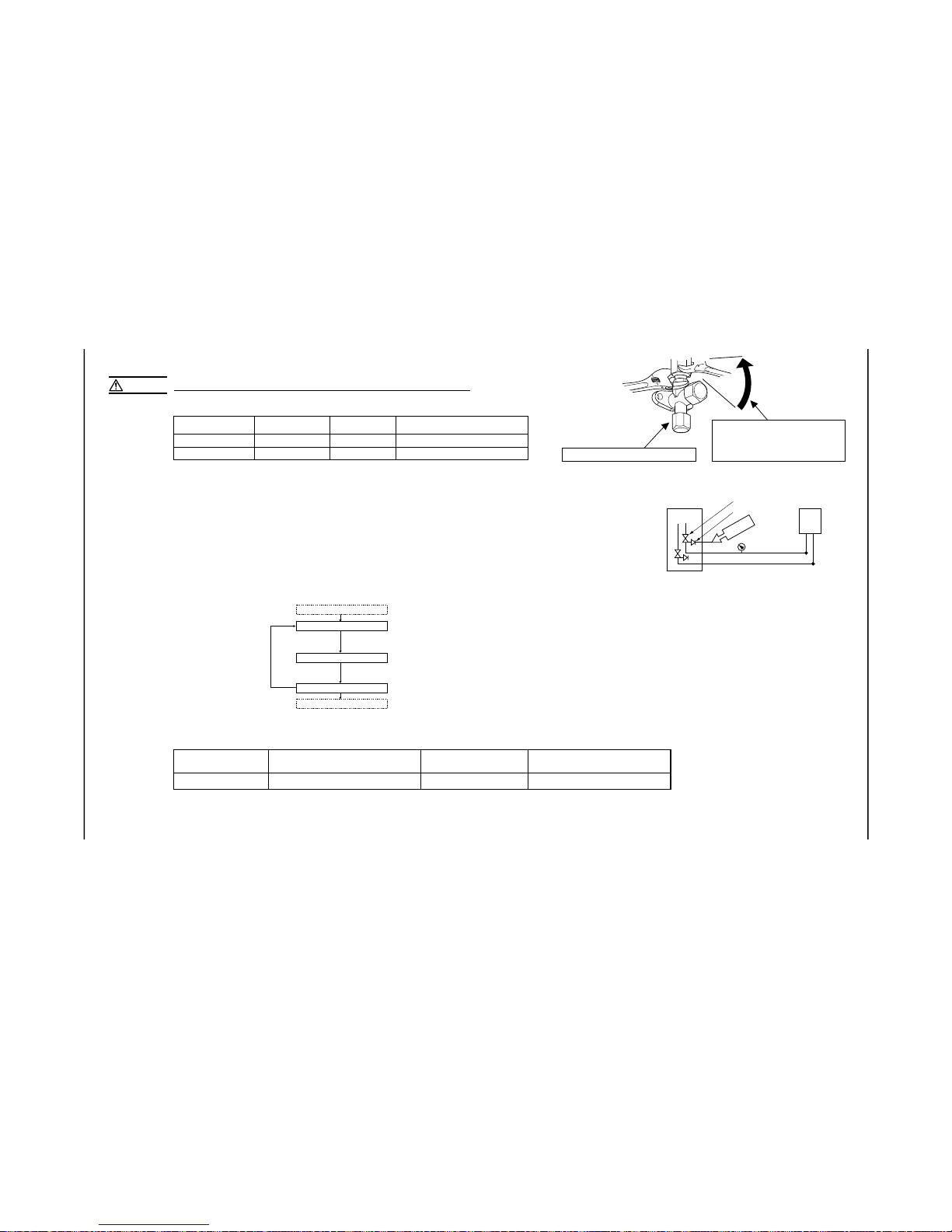
-
29
-
4. ELECTRICAL WIRING WORK For details of electrical cabling, refer to the indoor unit installation manual.
7) Additional refrigerant charge
0.02 1.40 15
Model 40, 50, 60
Additional charge volume (kg)
per meter of refrigerant piping (liquid pipe φ6.35)
Refrigerant volume charged
for shipment at the factory (kg)
Installation’s pipe length (m)
covered without additional refrigerant charge
●
This unit contains factory charged refrigerant covering 15m of refrigerant piping and additional refrigerant charge on the installation site is not required for
an installation with up to 15m refrigerant piping.
When refrigerant piping exceeds 15m, additionally charge an amount calculated from the pipe length and the above table for the portion in excess of 15m.
●
If a n existing pipe syste m is u sed, a required refri gerant charge volume will vary depending o n the liquid pipe size. For fur ther informatio n, please see
“5. UTILIZATION OF EXISTING PIPING.”
Are the existing units our products?
YES
START
YES YES
Are an outdoor unit and an indoor unit connected to the
existing pipe system to reuse?
Does the existing pipe system to reuse satisfy all of the following?
(1) The pipe length is 30m or less.
5. UTILIZATION OF EXISTING PIPING.
Check whether an existing pipe system is reusable or not by using the following flow chart.
Electrical installation work must be performed by an electrical installation service provider qualified by a power provider of the country.
Electrical installation work must be executed according to the technical standards and other regulations applicable to electrical installations in the country.
●
Do not use any supply cord lighter than one specified in parentheses for each type below.
- braided cord (code designation 60245 IEC 51),
- ordinary tough rubber sheathed cord (code designation 60245 IEC 53)
- flat twin tinsel cord (code designation 60227 IEC 41);
Use polychloroprene sheathed flexible cord (code designation 60245 IEC57) for supply cords of parts of appliances for outdoor use.
●
Ground the unit. Do not connect the grounding wire to a gas pipe, water pipe, lightning rod or telephone grounding wire
If impropery grounded, an electric shock or malfunction may result.
●
A grounding wire must be connected before connecting the power cable. Provide a grounding wire longer than the power cable.
●
The installation of an impulse withstanding type earth leakage breaker is necessary. A failure to install an earth leakage breaker can result in an
acccident such as an electric shock or a fire.
●
Do not turn on the power until the electrical work is completeted .
●
Do not use a condensive capacitor for power factor improvement under any circumstances. (It dose not improve power factor, while it can cause
an abnormal overheat accident)
●
For power supply cables, use conduits.
●
Do not lay electronic control cables (remote control and signaling wires) and other cables together outside the unit. Laying them together can result
in the malfunctioning or a failure of the unit due to electric noises.
●
Fasten cables so that may not touch the piping, etc.
●
When cables are connected, make sure that all electrical components within the electrical component box are free of loose connector coupling or
terminal connection and then attach the cover securely. (Improper cover attachment can result in malfunctioning or a failure of the unit, if water
penetrates into the box.)
●
Always use a three-core cable for an indoor-outdoor connecting cable. Never use a shield cable.
Take care so that installed pipes may not touch
components within a unit.
If touching with an internal component
, it will generate abnormal sounds and/or vibrations.
4) On-site piping work
IMPORTANT
How to remove the side cover
●
Carry out the on site piping work with the operation valve fully closed.
●
Give sufficient protection to a pipe end (compressed and blazed, or with an adhesive tape) so
that water or foreign matters may not enter the piping.
●
Bend a pipe to a radius as large as practical.(R100〜R150) Do not bend a pipe repeatedly to correct
its form.
●
Flare connection is used between the unit and refrigerant pipe. Flare a pipe after engaging a
flare nut onto it. Flare dimensions for R410A are different from those for conventional R407C.
Although we recommend the use of flaring tools designed specifically for R410A, conventional
flaring tools can also be used by adjusting the measurement of protrusion B with a protrusion
control gauge.
●
Tighten a flare joint securely with a double spanner.
Please remove the screw of a side cover and remove to the front.
A
B
Flared pipe end : A (mm)
φ6.35
φ12.7
Copper
pipe outer
diameter
0
ー0.4
A
9.1
16.6
Copper pipe protrusion for flaring : B
(mm)
φ6.35
φ12.7
Copper
pipe outer
diameter
In the case of a rigid (clutch) type
With an R410A tool With a conventional tool
0〜0.5 1.0〜1.5
CAUTION
Do not apply force beyond proper fastening torque in tightening the flare nut.
Fix both liquid and gas service valves at the valve main bodies as illustrated on the right, and then fasten them,
applying appropriate fastening torque.
Tightening angle (° )
Tightening torque (N-m)
φ6.35 (1/4")
φ12.7 (1/2")
14〜18
49〜61
45〜60
30〜45
150
250
Use a torque wrench. If a torque wrench is
not available, fasten the flare nut manually
first and then tighten it further, using the
left table as a guide.
Recommended length of a tool handle (mm)Operation valve size (mm)
Do not hold the valve cap area with a spanner.
5) Air tightness test
① Although outdoor and indoor units themselves have been tested for air tightness at the factory, check the connecting pipes after the installation work for air tightness
from the operation valve’s check joint equipped on the outdoor unit side. While conducting a test, keep the operation valve shut all the time.
a) Raise the pressure to 0.5 MPa, and then stop. Leave it for five minutes to see if the pressure drops.
b) Then raise the pressure to 1.5 MPa, and stop. Leave it for five more minutes to see if the pressure drops.
c) Then raise the pressure to the specified level (4.15 MPa), and record the ambient temperature and the pressure.
d) If no pressure drop is observed with an installation pressurized to the specified level and left for about one day, it is acceptable. When the ambient Temperature fall
1℃, the pressure also fall approximately 0.01 MPa. The pressure, if changed, should be compensated for.
e) If a pressure drop is observed in checking e) and a) – d), a leak exists somewhere. Find a leak by applying bubble test liquid to welded parts and flare joints and
repair it. After repair, conduct an air-tightness test again.
② In conducting an air-tightness test, use nitrogen gas and pressurize the system with nitrogen gas from the gas side. Do not use a medium other than nitrogen gas
under any circumstances.
Gas side
operation valve
Check joint
Pressur
ize
Close
Outdoor unit
Indoor unit
<Work flow>
6) Evacuation
Pay attention to the following points in addition to the above for the R410A and
compatible machines.
○
To prevent a different oil from entering, assign dedicated tools, etc. to each refrigerant
type. Under no circumstances must a gauge manifold and a charge hose in particular
be shared with other refrigerant types (R22, R407C, etc.).
○ Use a counterflow prevention adapter to prevent vacuum pump oil from entering the
refrigerant system.
Airtighteness test completed
Fill refrigerant
Vacuum gauge check
Vacuuming completed
Vacuuming begins
Run the vacuum pump for at least one hour after the vacuum
gauge shows -101kPa or lower. (-755mmHg or lower)
Confirm that the vacuum gauge indicator does not rise even if
the system is left for one hour or more.
When the system has remaining moisture
inside or a leaky point, the vacuum gauge
indicator will rise.
Check the system for a leaky point and
then draw air to create a vacuum again.
Screw
Side cover
(1) Calculate a required refrigerant charge volume from the following table.
 Loading...