

Mitsubishi Heavy Industries SRK20HG-S, SRK28HG-S, SRK40HG-S Technical Manual

-
3
-
WALL MOUNTED TYPE
ROOM AIR-CONDITIONER
TECHNICAL MANUAL
Collection data
Manual No. ’07
.
SRK-T
.
068
(Split system, air to air heat pump type)
SRK20HG-S
SRK28HG-S
SRK40HG-S

-
1
-
CONTENTS
1. GENERAL INFORMATION.............................................................................. 1
1.1 Specific features ....................................................................................... 1
1.2 How to read the model name ................................................................... 1
2. SELECTION DATA .......................................................................................... 2
2.1 Specifications ........................................................................................... 2
2.2 Range of usage & limitations .................................................................. 5
2.3 Exterior dimensions ................................................................................. 5
2.4 Piping system ........................................................................................... 7
2.5 Selection chart .......................................................................................... 8
3. ELECTRICAL DATA ........................................................................................ 9
3.1 Electrical wiring ........................................................................................ 9
4. OUTLINE OF OPERATION CONTROL BY MICROCOMPUTER ................... 10
4.1 Operation control function by remote control switch ........................... 10
4.2 Unit ON/OFF button .................................................................................. 11
4.3 Power blackout auto restart function ..................................................... 11
4.4 Custom cord switching procedure ......................................................... 12
4.5 Flap control ............................................................................................... 12
4.6 Timer operation ......................................................................................... 13
4.7 Outline of heating operation .................................................................... 14
4.8 Outline of cooling operation .................................................................... 17
4.9 Outline of dehumidifying operation ........................................................ 18
4.10 Outline of automatic operation................................................................ 19
4.11 Outline of clean operation ....................................................................... 19
4.12 Protective control function ...................................................................... 20
5. APPLICATION DATA ....................................................................................... 22
5.1 Selection of location for installation ....................................................... 23
5.2 Installation of indoor unit......................................................................... 24
5.3 Installation of outdoor unit ...................................................................... 27
5.4 Connection of refrigerant piping ............................................................. 27
5.5 Test run ...................................................................................................... 29
5.6 Precautions for wireless remote control installation and
operation ................................................................................................... 29
6. MAINTENANCE DATA .................................................................................... 30
6.1 Trouble shooting....................................................................................... 30
6.2 Servicing.................................................................................................... 35
7. REFRIGERANT PIPING INSTALLATION/SERVICING MANUAL
FOR AIR CONDITIONERS USING R410A...................................................... 36
-
1
-
1.2 How to read the model name
Example : SR K 20 H G - S
1 GENERAL INFORMATION
1.1 Specific features
The “MITSUBISHI HEAVY INDUSTRIES, LTD.” room air-conditioner: SRK series are of split and wall mounted type and the unit
consists of indoor unit and outdoor unit with refrigerant precharged in factory. The indoor unit is composed of room air cooling or
heating equipment with operation control switch and the outdoor unit is composed of condensing unit with compressor.
(1) Remote control flap
The flap can be automatically controlled by operating wireless remote control.
¡ Swing: This will swing the flap up and down.
¡ Memory flap: Once the flap position is set, the unit memorizes the position and continues to operate at the same position from
the next time.
(2) Automatic Operation
When the remote control switch is set on “auto(
) ”, it will either automatically decide operation mode such as cooling, heating
and thermal dry, or operate in the operation mode before it has been turned to automatic control.
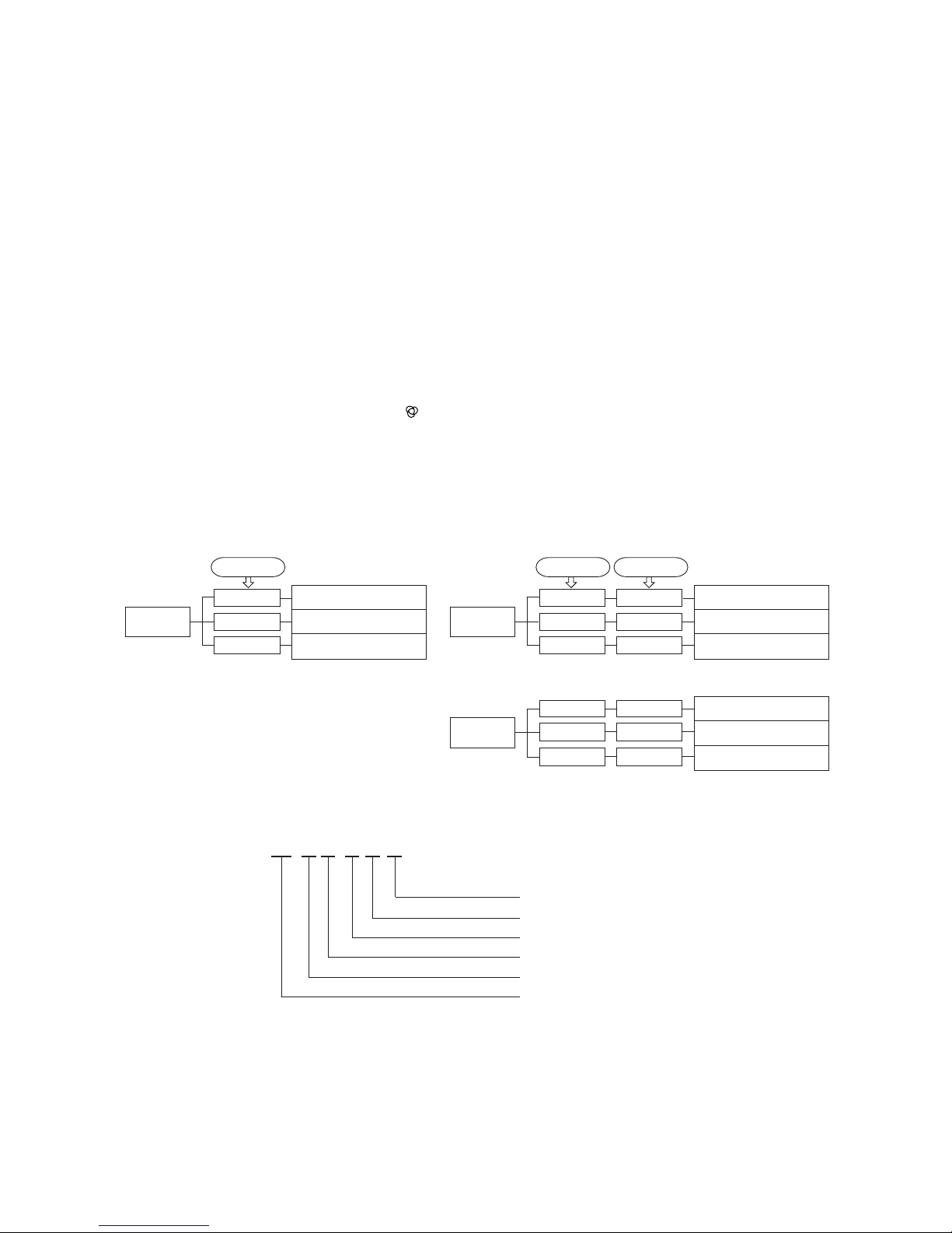
(3) Self diagnosis function
¡ We are constantly trying to do better service to our customers by installing such judges that show abnormality of operation as
follows.
R410A models
Series No.
Heat pump type
Product capacity
Wall mounted type
Split type room air-conditioner
Room temperature sensor error
Indoor fan motor error
Heat exchanger sensor error
2 time flash
6 time flash
TIMER light
ON
1 time flash
RUN light
Outdoor unit heat exchanger
sensor error
Discharge pipe sensor error
Outdoor temperature sensor error
2 time flash
4 time flash
RUN light
keeps flashing
1 time flash
OFF
OFF
OFF
TIMER light Outdoor (LED)
Error of signal transmission
Trouble of outdoor unit
Over heat of compressor
2 time flash
5 time flash
RUN light
ON
2 time flash
5 time flash
6 time flash 6 time flash
-
2
-
Item
Model
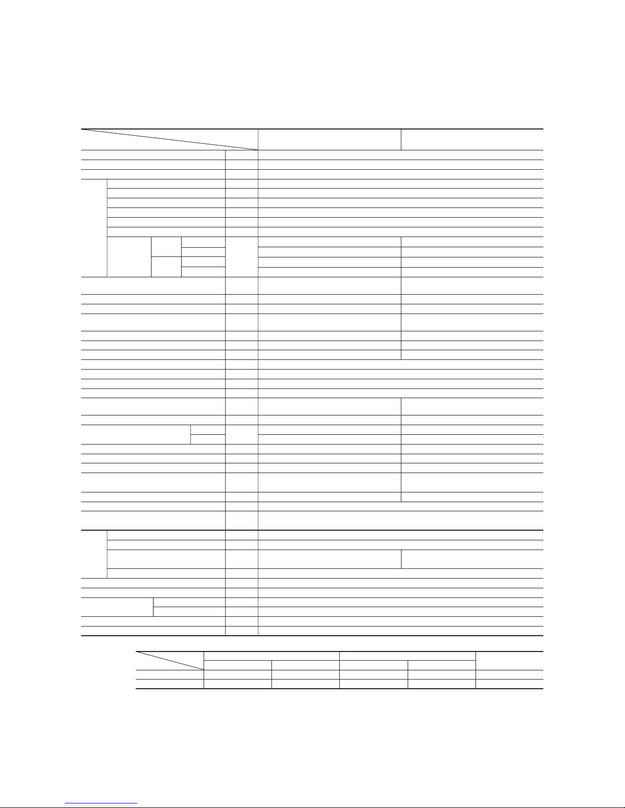
SRK20HG-S SRC20HG-S
Cooling capacity
(1)
W 2070
Heating capacity
(1)
W 2220
Power source 1 Phase, 220/230/240V, 50Hz
Cooling input kW 0.64
Running current (Cooling) A 3.1/3.0/2.9
Heating input kW 0.61
Running current (Heating) A 3.0/2.9/2.8
Inrush current A 18.9
COP Cooling: 3.23 Heating: 3.64
Cooling
Sound level Hi: 34 , Me: 30 , Lo: 27 46
Noise level
Power level
dB
52 60
Heating
Sound level Hi: 34 , Me: 31 , Lo: 27 46
Power level 52 60
Exterior dimensions
Height × Width × Depth
mm
268 × 790 × 199 540 × 780 × 290
Color Fine snow Stucco white
Net weight kg 8.5 29
Refrigerant equipment
Compressor type & Q’ty
– RM-B5077MNE4 (Rotary type) × 1
Motor kW – 0.65
Starting method – Line starting
Heat exchanger Louver fins & inner grooved tubing Straight fin & inner grooved tubing
Refrigerant control Capillary tubes + Electronic expansion valve
Refrigerant
(3)
kg R410A 0.95 (Pre-Charged up to the piping length of 15m)
Refrigerant oil R 0.35 (MA68)
Deice control Microcomputer control
Air handling equipment
Fan type & Q’ty
Tangential fan × 1 Propeller fan × 1
Motor W 14 14
(Cooling) 7.5 27
Air flow (at High)
(Heating)
CMM
7.5 27
Air filter, Q’ty Polypropylene net (washable) × 2–
Shock & vibration absorber – Cushion rubber (for compressor)
Electric heater ––
Operation control
Operation switch
Wireless-Remote control –
Room temperature control Microcomputer thermostat –
Pilot lamp RUN (Green), TIMER (Yellow), HI POWER (Green), ECONO (Orange)
Safety equipment
O.D mm (in) Liquid line: φ6.35 (1/4″) Gas line: φ9.52 (3/8″)
Connecting method Flare connecting
Attached length of piping Liquid line: 0.4 m
Gas line : 0.33 m
–
Insulation Necessary (Both sides)
Drain hose Connectable
Power source cord 2 m (3 cores with Earth)
Size × Core number 1.5 mm2 × 4 cores (Including earth cable)
Connection wiring
Connecting method Terminal block (Screw fixing type)
Accessories (included)
Mounting kit, Clean filter (Natural enzyme filter × 1, Photocatalytic washable deodorizing filter × 1)
Optional parts –
Notes (1) The data are measured at the following conditions.
2 SELECTION DATA
2.1 Specifications
Model SRK20HG-S (Indoor unit)
SRC20HG-S (Outdoor unit)
Item Indoor air temperature Outdoor air temperature
Standards
Operation DB WB DB WB
Cooling 27ºC 19ºC 35ºC 24ºC ISO-T1, JIS C9612
Heating 20ºC – 7ºC 6ºC ISO-T1, JIS C9612
(2) The operation data are applied to the 220/230/240V districts respectively.
(3) The refrigerant quantity to be charged includes the refrigerant in 15 m connecting piping.
(Purging is not required even for the short piping.)
Operation data
(1)
Refrigerant
piping
Frost protection, Serial signal error protection, Compressor overheat protection,
High pressure control, Indoor fan motor error protection
The piping length is 7.5 m.
(220/230/240V)
-
3
-
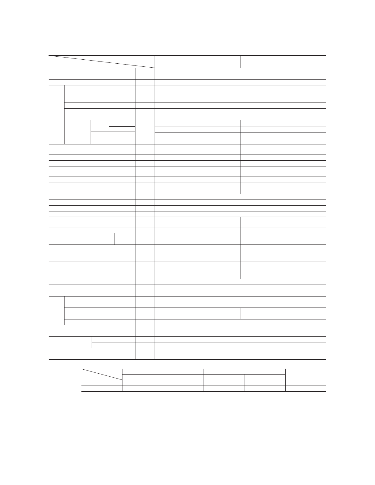
Model SRK28HG-S (Indoor unit)
SRC28HG-S (Outdoor unit)
Item
Model
SRK28HG-S SRC28HG-S
Cooling capacity
(1)
W 2600
Heating capacity
(1)
W 2800
Power source 1 Phase, 220/230/240V, 50Hz
Cooling input kW 0.81
Running current (Cooling) A 3.8/3.7/3.6
Heating input kW 0.77
Running current (Heating) A 3.7/3.5/3.3
Inrush current A 17.2
COP Cooling: 3.21 Heating: 3.64
Cooling
Sound level Hi: 39, Me: 33, Lo: 30 46
Noise level
Power level
dB
55 60
Heating
Sound level Hi: 40, Me: 33, Lo: 29 46
Power level 56 60
Exterior dimensions
Height × Width × Depth
mm
268 × 790 × 199 540 × 780 × 290
Color Fine snow Stucco white
Net weight kg 8.5 31
Refrigerant equipment
Compressor type & Q’ty
– 5PS102DAB (Rotary type) × 1
Motor kW – 0.7
Starting method – Line starting
Heat exchanger Louver fins & inner grooved tubing Straight fin & inner grooved tubing
Refrigerant control Capillary tubes + Electronic expansion valve
Refrigerant
(3)
kg R410A 0.85 (Pre-Charged up to the piping length of 15m)
Refrigerant oil R 0.35 (RB68A)
Deice control Microcomputer control
Air handling equipment
Fan type & Q’ty
Tangential fan × 1 Propeller fan × 1
Motor W 14 15
(Cooling) 8.5 29
Air flow (at High)
(Heating)
CMM
10.0 29
Air filter, Q’ty Polypropylene net (washable) × 2–
Shock & vibration absorber – Cushion rubber (for compressor)
Electric heater ––
Operation control
Operation switch
Wireless-Remote control –
Room temperature control Microcomputer thermostat –
Pilot lamp RUN (Green), TIMER (Yellow), HI POWER (Green), ECONO (Orange)
Safety equipment
O.D mm (in) Liquid line: φ6.35 (1/4″) Gas line: φ9.52 (3/8″)
Connecting method Flare connecting
Attached length of piping Liquid line: 0.4 m
Gas line : 0.33 m
–
Insulation Necessary (Both sides)
Drain hose Connectable
Power source cord 2 m (3 cores with Earth)
Size × Core number 1.5 mm2 × 4 cores (Including earth cable)
Connection wiring
Connecting method Terminal block (Screw fixing type)
Accessories (included)
Mounting kit, Clean filter (Natural enzyme filter × 1, Photocatalytic washable deodorizing filter × 1)
Optional parts –
Notes (1) The data are measured at the following conditions.
Item Indoor air temperature Outdoor air temperature
Standards
Operation DB WB DB WB
Cooling 27ºC 19ºC 35ºC 24ºC ISO-T1, JIS C9612
Heating 20ºC – 7ºC 6ºC ISO-T1, JIS C9612
(2) The operation data are applied to the 220/230/240V districts respectively.
(3) The refrigerant quantity to be charged includes the refrigerant in 15 m connecting piping.
(Purging is not required even for the short piping.)
Operation data
(1)
Refrigerant
piping
The piping length is 7.5 m.
(220/230/240V)
Frost protection, Serial signal error protection, Compressor overheat protection,
High pressure control, Indoor fan motor error protection
-
4
-
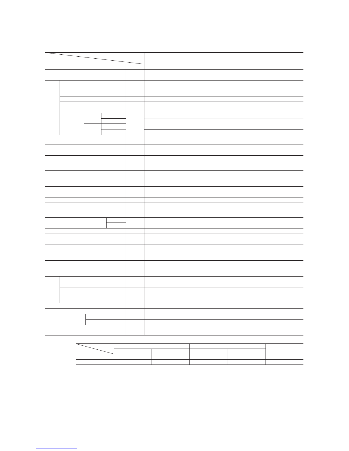
Model SRK40HG-S (Indoor unit)
SRC40HG-S (Outdoor unit)
Item
Model
SRK40HG-S SRC40HG-S
Cooling capacity
(1)
W 3600
Heating capacity
(1)
W 3920
Power source 1 Phase, 220/230/240V, 50Hz
Cooling input kW 1.12
Running current (Cooling) A 5.3/5.2/5.1
Heating input kW 1.15
Running current (Heating) A 5.4/5.3/5.2
Inrush current A 25.2
COP Cooling: 3.21 Heating: 3.41
Cooling
Sound level Hi: 40, Me: 38, Lo: 34 49
Noise level
Power level
dB
56 63
Heating
Sound level Hi: 40, Me: 38, Lo: 34 52
Power level 57 66
Exterior dimensions
Height × Width × Depth
mm
268 × 790 × 199 540 × 780 × 290
Color Fine snow Stucco white
Net weight kg 8.5 38
Refrigerant equipment
Compressor type & Q’ty
– 5KS150DBQ01 (Rotary type) × 1
Motor kW – 1.1
Starting method – Line starting
Heat exchanger Louver fins & inner grooved tubing Straight fin & inner grooved tubing
Refrigerant control Capillary tubes + Electronic expansion valve
Refrigerant
(3)
kg R410A 1.15 (Pre-Charged up to the piping length of 15m)
Refrigerant oil R 0.43 (RB68A or Freol Alpha 68M)
Deice control Microcomputer control
Air handling equipment
Fan type & Q’ty
Tangential fan × 1 Propeller fan × 1
Motor W 14 22
(Cooling) 9.0 32
Air flow (at High)
(Heating)
CMM
10.0 32
Air filter, Q’ty
Polypropylene net (washable) × 2
–
Shock & vibration absorber – Cushion rubber (for compressor)
Electric heater ––
Operation control
Operation switch
Wireless-Remote control –
Room temperature control Microcomputer thermostat –
Pilot lamp RUN (Green), TIMER (Yellow), HI POWER (Green), ECONO (Orange)
Safety equipment
O.D mm (in) Liquid line: φ6.35 (1/4″) Gas line: φ12.7 (1/2″)
Connecting method Flare connecting
Attached length of piping Liquid line: 0.4 m
Gas line : 0.33 m
–
Insulation Necessary (Both sides)
Drain hose Connectable
Power source cord 2 m (3 cores with Earth)
Size × Core number 1.5 mm2 × 4 cores (Including earth cable)
Connection wiring
Connecting method Terminal block (Screw fixing type)
Accessories (included)
Mounting kit, Clean filter (Natural enzyme filter × 1, Photocatalytic washable deodorizing filter × 1)
Optional parts –
Notes (1) The data are measured at the following conditions.
Item Indoor air temperature Outdoor air temperature
Standards
Operation DB WB DB WB
Cooling 27ºC 19ºC 35ºC 24ºC ISO-T1, JIS C9612
Heating 20ºC – 7ºC 6ºC ISO-T1, JIS C9612
(2) The operation data are applied to the 220/230/240V districts respectively.
(3) The refrigerant quantity to be charged includes the refrigerant in 15 m connecting piping.
(Purging is not required even for the short piping.)
Operation data
(1)
Refrigerant
piping
The piping length is 7.5 m.
(220/230/240V)
Frost protection, Serial signal error protection, Compressor overheat protection,
High pressure control, Indoor fan motor error protection

-
5
-
2.2 Range of usage & limitations
Indoor return air temperature
(Upper, lower limits)
Refrigerant line (one way) length Max. 15m
All models
Power source voltage Rating ± 10%
Voltage at starting Min. 85% of rating
Frequency of ON-OFF cycle
ON and OFF interval Max. 3 minutes
Outdoor air temperature
(Upper, lower limits)
Vertical height difference between
outdoor unit and indoor unit
Max. 10m (Outdoor unit is higher)
Max. 10m (Outdoor unit is lower)
Item
Models
Max. 10 times/h
(Inching prevention 3 minutes)
Cooling operation : Approximately 21 to 32˚C
Heating operation : Approximately 15 to 30˚C
Cooling operation : Approximately 21 to 43˚C
Heating operation : Approximately -5 to 21˚C
2.3 Exterior dimensions
(1) Indoor unit
Models All models
Piping hole (ø65)
( )
Piping hole (ø65)
53.5
380.6
Pipng for Liquid 448.6 (ø6.35)
20, 28 : ø9.52
40 : ø12.7
Pipng for Gas
Drain hose 520 (ø16)
53.5
44.5
252.2
7.5
8.3
102.5
585
102.5
133.5450206.5
202450138
44.5
43.2
39.3
200
45
45
60
17.5
60
27
788
60
9
45
199
3
Terminal block
Piping hole right(left)
268
790
A
VIEW A
→
Unit: mm
-
6
-
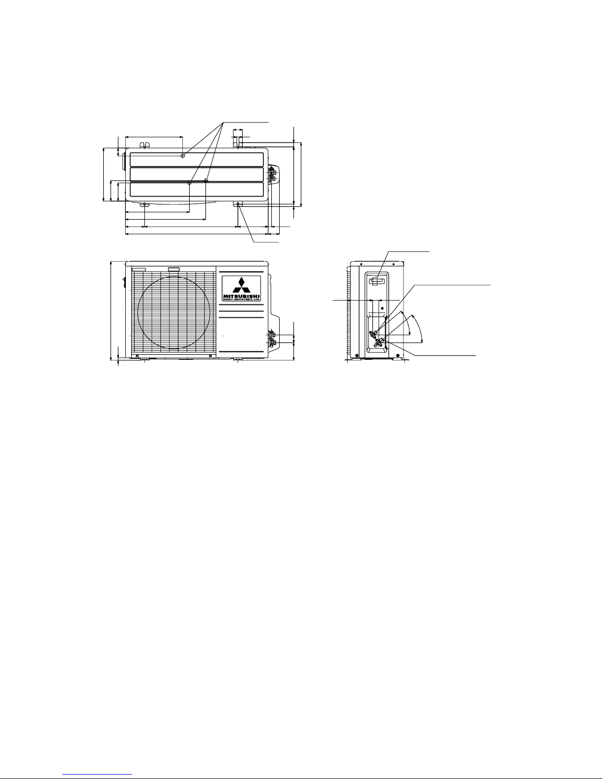
(2) Outdoor unit
Models All models
2-16×12
Drain holes (ø20)
138.4
40
˚
61.9
18.9165.1510104.9
439.1
111.4
99.4
349.5
313.1
43.1
290
12
50
350
23.5312.5
14
33.5
40
˚
42.595.9
14
540
780
Service valve (Liquid)
Flare connection ø6.35 (1/4'')
Service valve (Gas)
Flare connection
20, 28: ø9.52 (3/8'')
40: ø12.7 (1/2'')
Terminal block
-
7
-
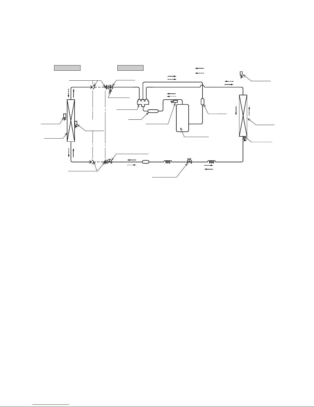
2.4 Piping system
Outdoor unitIndoor unit
Flare connecting
Room temp.
sensor
Heat
exchanger
Flare connecting
Electronic
expansion valve
Piping
(Liquid)
ø6.35
Heat
exchanger
sensor
Piping
(Gas)
ø9.52
Service valve
(Gas)
Check joint
4 way valve
Service valve (Liquid)
Strainer
Capillary tube Capillary tube
Compressor
Accumulator
Discharge temp.
sensor
Muffler
Heat exchanger
sensor
Heat
exchanger
Outdoor air
temp. sensor
Cooling cycle
Heating cycle
Models SRK20HG-S, 28HG-S, 40HG-S
-
8
-
Length 15m
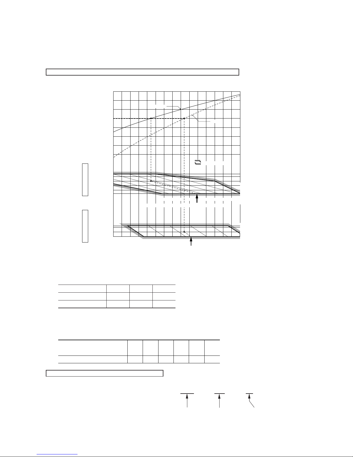
2.5 Selection chart
Correct the cooling and heating capacity in accordance with the conditions as follows. The net cooling and heating capacity can be
obtained in the following way.
Net capacity = Capacity shown on specification ✕ Correction factors as follows.
(1) Coefficient of cooling and heating capacity in relation to temperatures
(2) Correction of cooling and heating capacity in relation to one way length of refrigerant piping
It is necessary to correct the cooling and heating capacity in relation to the one way piping length between the indoor and outdoor
units.
(3) Correction relative to frosting on outdoor heat exchanger during heating
In additions to the foregoing corrections (1), (2) the heating capacity needs to be adjusted also with respect to the frosting on the
outdoor heat exchanger.
How to obtain the cooling and heating capacity
Example : The net cooling capacity of the model SRK20HG-S with the piping length of 15m, indoor wet-bulb temperature at 19.0˚C
and outdoor dry-bulb temperature 35˚C is Net cooling capacity = 2070 ✕ 0.975 ✕ 1.0 = 2018 W
SRK20HG-S
Factor by air
temperatures
15
ISO-T1 Standard ConditionOutdoor air W.B. temperature ˚C W.B.
1005-5
16 18 20 22 24
20
ISO-T1 Standard ConditionIndoor air W.B. temperature ˚C W.B.
Heating
Applicable range
27
25
20
15
21
25
30
35
40
0.6
0.7
0.8
0.9
1.0
1.1
1.2
1.3
43
Cooling
Heating operation
Indoor air D.B.
temperature
˚C D.B.
Cooling operation
Outdoor air D.B.
temperature
˚C D.B.
Coefficient of cooling &
Heating capacity in
relation to temperature
Piping length [m]
Cooling
Heating
7
1.0
1.0
10
0.99
1.0
15
0.975
1.0
Air inlet temperature of
outdoor unit in ˚C WB
Adjustment coefficient
-5
0.91-30.88-10.8610.8730.9251.00
-
9
-
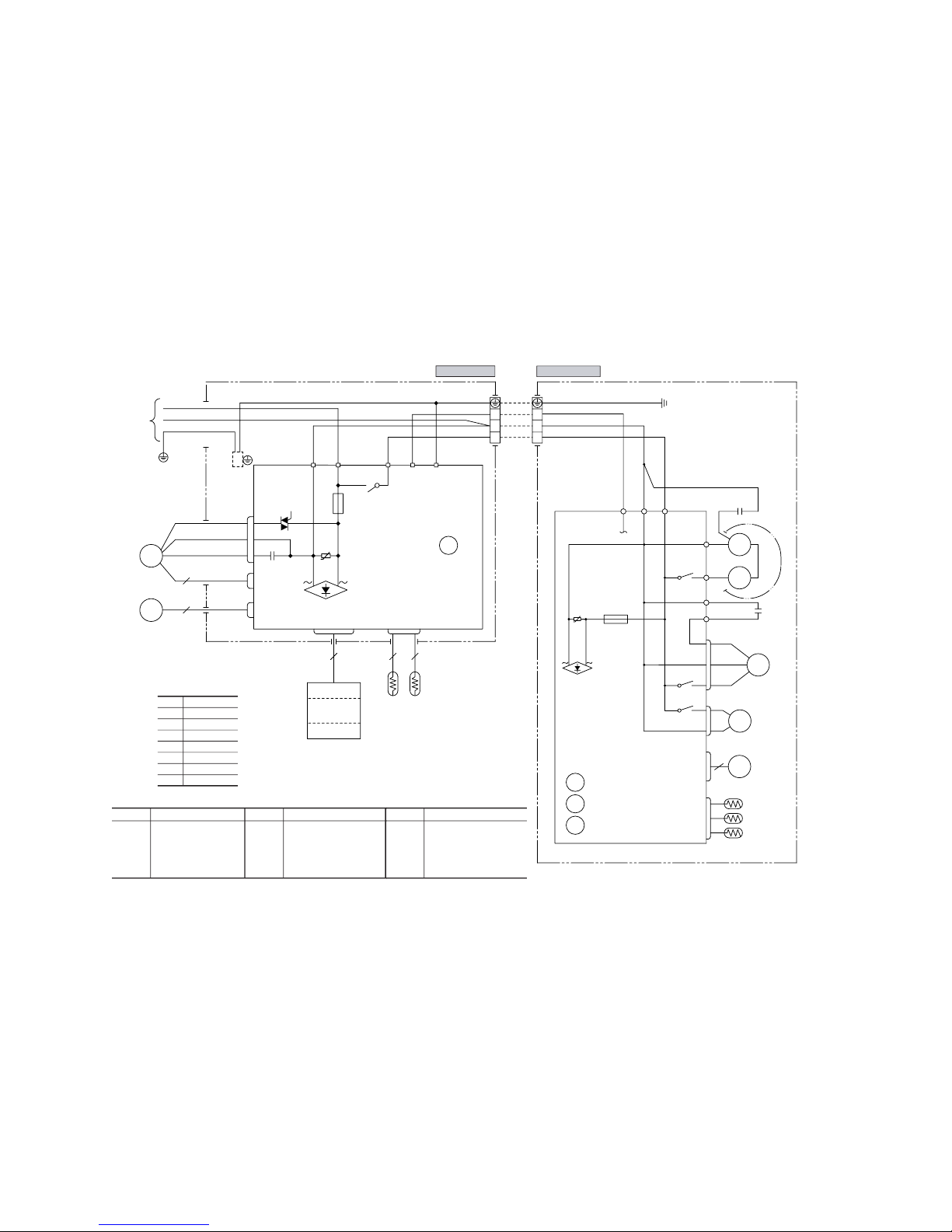
3 ELECTRICAL DATA
3.1 Electrical wiring
Models SRK20HG-S, 28HG-S, 40HG-S
BR
BR
LB
G
Y/G
Y/G Y/G
Y/G
Th1 Th2
R-AMP
WIRELESS
DISPLAY
WH
WH
WH
3
ZNR
N
CNGCNE
250V 3.15A
F
CNM
BK
BK BK
52C
52C-3
1
5
52C-4
BACK UP SW
822
5
U
FM
I
SM
J
RD
RD RD
TB TB
3
2/N
1
3
2/N
1
EXCHANGER
HEAT
CNW
CFI
IC15
CNU
WH
RD
BR
3
52C
Printed circuit
board
BK
BL
BR
Y
WH
LB
Y/G
RD
Color symbol
Black
Blue
Brown
Yellow
White
Light blue
Yellow/Green
Red
Meaning of marks
Symbol
Parts name
Symbol
Parts name
Symbol
Parts name
CM
F
FM
I
FM
O
SM
Th
1
Compressor motor
Fuse
Fan motor (Indoor)
Fan motor (Outdoor)
CFI
CFO
Capacitor for FM
I
Capacitor for FM
O
Motor Protector for CM
Magnetic contactor
Auxiliary relay
Flap motor
Room temp.sensor
Th
2
Heat exch.sensor (Indoor unit)
Th
4
Th
5
Th
6
ZNR
20S
DS
52X
1-3
Heat exch.sensor (Outdoor unit)
TB Terminal block
52C
51C
Outdoor air temp.sensor
Discharge pipe temp.sensor
Varistor
4 way valve (coil)
Diode stack
Power source
1 Phase
220/230/240V 50Hz
Outdoor unit
Indoor unit
D.S
CFO
Y
RD
CM2
RD
J
WH
N
BK
L
WH
CM1
52X1
BK
Y
WH
CC
CM
52X2
3
5
CNU
1
1
CNE
FMo
EEV
Th6
Th4
CNG
Th5
250V 3.15A
F
CNB
20S
BK
51C
52X3
3
6
PRINTED CIRCUIT
BOARD
ZNR
U
52X1
52X2
52X3
-
10
-
4 OUTLINE OF OPERATION CONTROL BY MICROCOMPUTER
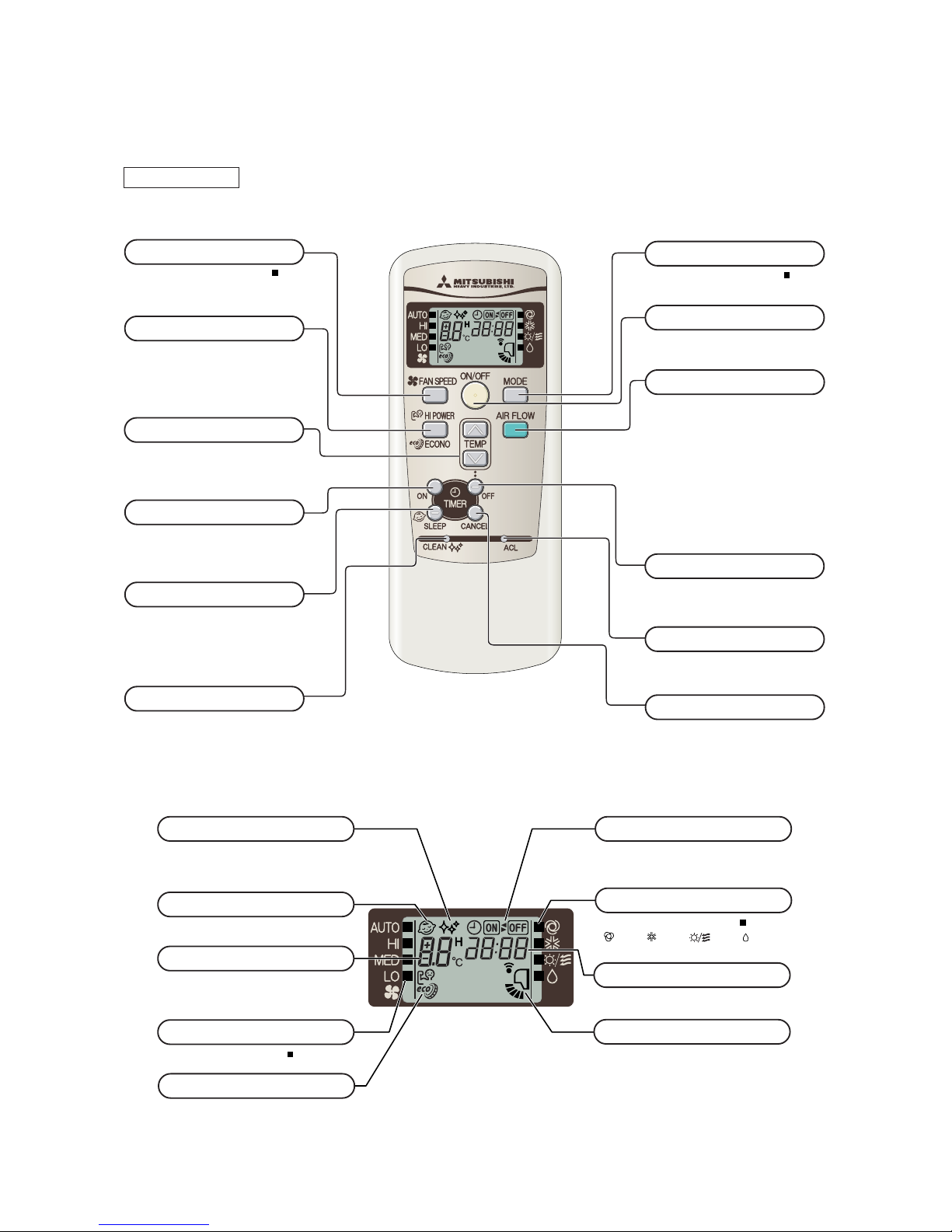
4.1 Operation control function by remote control switch
Remote control
Models All models
◆ Operation selection
◆ Indication selection
FAN SPEED button
Each time the button is pushed, the
indicator is switched over in turn.
•
The above illustration shows all controls, but in practice
only the relevant parts are shown.
OPERATION MODE select button
Each time the button pushed, the
indicator is switched over in turn.
ON/OFF (luminous) button
Press for starting operation, press again
for stopping.
HI POWER/ECONO button
This button changes the HIGH POWER/
ECONOMY mode.
AIR FLOW (UP/DOWN) button
This button changes the air flow (up/down) mode.
SLEEP button
This button selects SLEEP operation.
CLEAN switch
This switch changes the CLEAN mode.
ON TIMER button
This button selects ON TIMER operation.
This button cancels the ON timer, OFF
timer, and SLEEP operation.
CANCEL button
RESET switch
Switch for resetting microcomputer and
setting time.
SLEEP indicator
Indicates during SLEEP operation.
TEMPERATURE indicator
Indicates set temperature.
(Does not indicate temperature when operation
mode is on AUTO)
FAN SPEED indicator
Indicates set air flow rate with lamp.
CLEAN indicator
Indicates during CLEAN operation.
ON/OFF TIMER indicator
Indicates during ON/OFF TIMER operation.
AIR FLOW indicator
Shows selected flap mode.
HI POWER/ECONO MODE indicator
Indicates during HIGH POWER/ECONOMY
mode operation.
[
OPERATION MODE indicator
Indicates selected operation with lamp.
(Auto)•(Cool)• (Heat) •(Dry)]
OFF TIMER button
This button selects OFF TIMER operation.
TEMPERATURE button
This button sets the room temperature.
(This button changes the present time and
TIMER time.)
TIME indicator
Indicates present time or timer setting time.
-
11
-
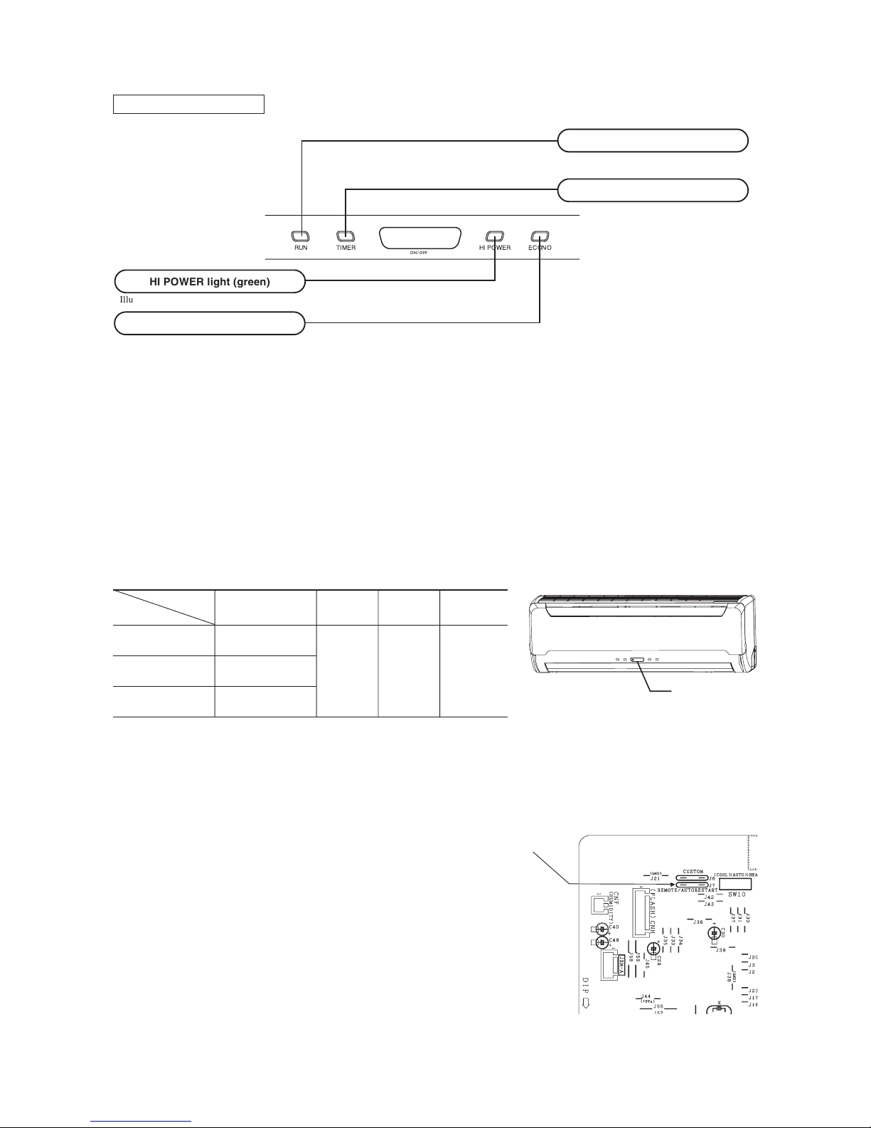
Unit indication selection
Models All models
ECONO light (orange)
Illuminates during ECONOMY operation.
RUN light (green)
Illuminates during operation
and CLEAN operation.
TIMER light (yellow)
Illuminates during TIMER operation.
HI POWER light (green)
Illuminates during HIGH POWER operation.
Unit ON/OFF button
4.2 Unit ON/OFF button
When the remote control batteries become weak, or if the remote control is lost or malfunctioning, this button may be used to turn the
unit on and off.
(1) Operation
Push the button once to place the unit in the automatic mode. Push it once more to turn the unit off.
(2) Details of operation
The unit will go into the automatic mode in which it automatically determines, from room temperature (as detected by sensor),
whether to go into the cooling, thermal dry or heating modes.
Function
Room temperature
Operation mode
setting
Fan speed Flap
Timer switch
Cooling About 24ºC
Thermal dry About 24ºC Auto Auto Continuous
Heating About 26ºC
4.3 Power blackout auto restart function
(1) Power blackout auto restart function is a function that records the operational status of the air-conditioner immediately prior to it
being switched off by a power cut, and then automatically resumes operations at that point after the power has been restored.
(2) The following settings will be cancelled:
(a) Timer settings
(b) High-power operations
Notes (1) The power blackout auto restart function is set at on when the air-conditioner is shipped from the
factory. Consult with your dealer if this function needs to be switched off.
(2) When power failure ocurrs, the timer setting is cancelled. Once power is resumed, reset the timer.
(3)
If the jumper wire (J7) “AUTO RESTART” is cut, auto restart is disabled. (See the diagram at right)
Jumper wire (J7)
-
12
-
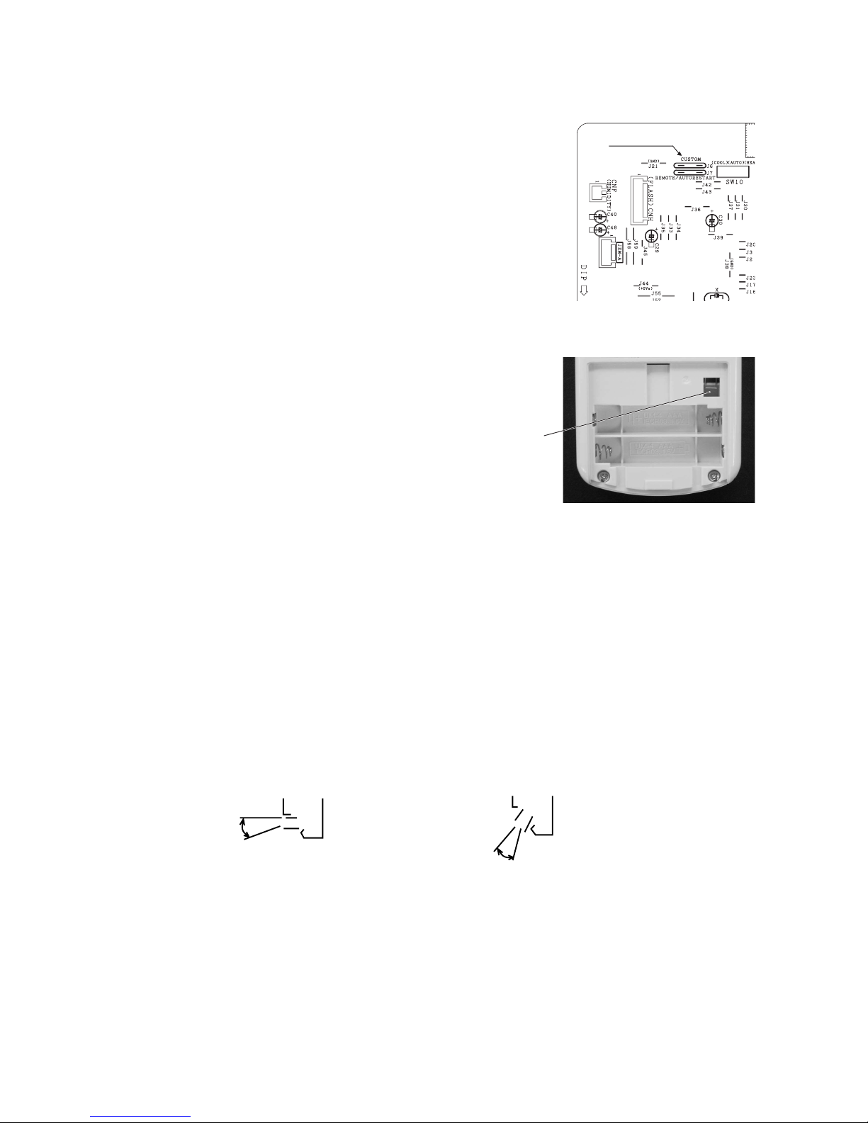
4.4 Custom cord switching procedure
If two wireless remote controls are installed in one room, in order to prevent wrong operation
due to mixed signals, please modify the printed circuit board in the indoor unit’s control box
and the remote control using the following procedure. Be sure to modify both boards. If only
one board is modified, receiving (and operation) cannot be done.
(1) Modifying the indoor unit’s printed circuit board
Take out the printed circuit board from the control box and cut off jumper wire (J6)
using wire cutters.
After cutting of the jumper wire, take measures to prevent contact with the other the lead
wires, etc.
(2) Modifying the wireless remote control
(a) Remove the battery.
(b) Cut the jumper wire shown in the figure at right.
Jumper wire (J6)
Cut
4.5 Flap control
Control the flap by AIRFLOW button on the wireless remote control.
(1) Swing flap
Flap moves in upward and downward directions continuously.
(2) When not operating
The flap returns to the position of air flow directly below, when operation has stopped.
(3) Memory flap (Flap stopped)
When you press the AIRFLOW button once while the flap is operating, it stops swinging at an angle. Since this angle is memorized
in the microcomputer, the flap will automatically be set at this angle when the next operation is started.
¡ Recommendable stopping angle of the flap
Horizontal
blowing
COOL•DRY
Slant forward
blowing
HEAT
-
13
-
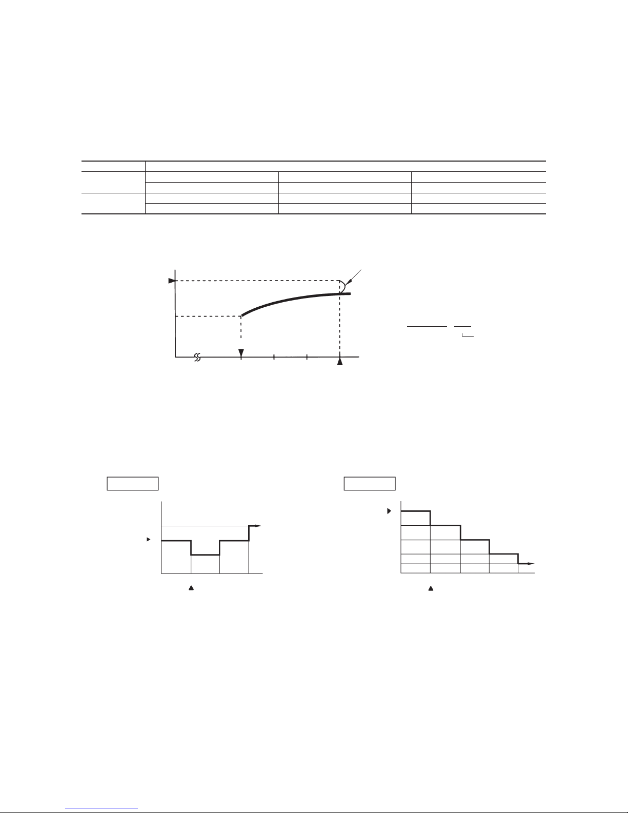
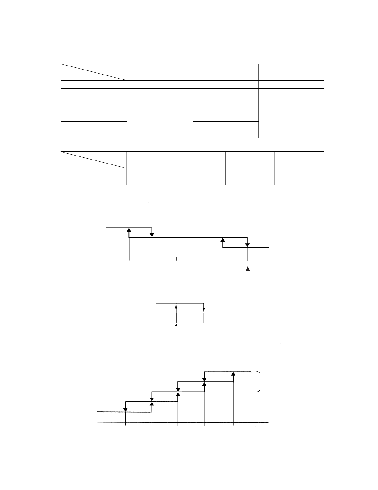
Timer operation
(time)
Temperature
setting (˚C)
Start
Heating
0
-1.0
-2.0
-3.0
-6.0
0 0.5 1.0 2.0
Start
Timer operation
(time)
Temperature
setting (˚C)
Cooling
+
1.0
0
-1.0
0 1.0 2.0
(2) Sleep timer operation
Pressing the SLEEP button causes the temperature to be controlled as shown in the following chart with respect to the set
temperature.
4.6 Timer operation
(1) Comfortable timer setting (ON timer)
(3) OFF timer operation
The Off timer can be set at a specific time (in 10-minute units) within a 24-hour period.
Corrects the starting time of next operation by
calculating the temperature difference.
(Example) Heating
Setting temperature
Room temperature
Operation starting time
Time
Setting time
15 min. 10 min. 5 min.
earlier earlier earlier
¡ If the difference (= Setting temperature – Room tempera-
ture) is 4ºC, the correction value is found to be +5 minutes from the table shown above so that the starting time
of next operation is determined as follows:
15 min. earlier + 5 min. = 20 min. earlier
↑↑
Current operation Correction value
start time
If the timer is set at ON when the operation select switch is set at the cooling or heating, or the cooling or heating in auto mode
operation is selected, the comfortable timer starts and determines the starting time of next operation based on the initial value of 15
minutes and the relationship between the room temperature at the setting time (temperature of room temperature sensor) and the
setting temperature. (Max. 60 minutes)
Operation mode Operation start time correction value (Min.)
3 < Room temp. – Setting temp. 1 < Room temp. – Setting temp. 3 Room temp. – Setting temp. 1
At cooling
+5 No change –5
3 < Setting temp. – Room temp. 2 < Setting temp. – Room temp. 3 Setting temp. – Room temp. 2
At heating
+5 No change –5
Notes (1) At 5 minutes before the timer ON time, operation starts regardless of the temperature of the room temperature sensor (Th1).
(2) This function does not operate when in the Dry or Auto Dry mode.
However, the operation in item (1) does operate in the Auto Dry mode.
(3) During the comfortable timer operation, both the RUN light and TIMER light illuminate and the TIMER light goes off after expiration of the timer, ON setting
time.
=
<
=
<
=
<
=
<
-
14
-
4.7 Outline of heating operation
(1) Operation of major functional components
(2) Fan speed switching
(a) Auto fan control
The indoor fan is automatically controlled in accordance with the difference between the room temperature (detected by the
room temperature sensor) and the thermostat setting as shown below.
(3) Thermostat operation
The compressor and outdoor fan and turned on and off as shown below according to the temperature setting.
(4) Hot keep
This function controls the indoor unit fan speed as shown below in accordance with the temperature sensed by the indoor heat
exchanger sensor.
(a) When the compressor and outdoor unit fan are operating
Indoor fan motor
Flaps
Display
52C
Outdoor fan motor
ON
ON or OFF
Lights up
ON
ON
ON or OFF
Lights up
ON
ON
OFF
Stop position control
Lights up or flashes
4-way valve
Depending on the stop mode
ON
Depending on the stop mode
When the compressor
command is OFF
When the compressor
command is ON
When the compressor goes
OFF due to an anomalous stop.
Functional
components
Item
Swing flap
Swing stop
Auto fan control
Speed 7
Speed 7
Speed 5
Speed 5
AUTO HIGH MED
Speed 3
Speed 3
LOW
Flow control
Fan speed switching
Speed 7
Speed 5
Speed 3
Thermostat setting point
-5 -4 -3 -2 -1 0
Speed 9
Speed 7
Speed 5
Speed 3
OFF
3430252015<SRK20HG-S>
4034302515<SRK28HG-S>
4337302318<SRK40HG-S>
Auto fan control,
or the set fan speed
Indoor heat exchanger temp. (˚C)
Set temp.
+1
Room temp.
OFF
ON
Compressor
Outdoor fan
 Loading...