

Mitsubishi Heavy Industries SRK18YL-S, SRK13YL-S, SRK10YL-S User Manual
Thank you for purchasing a MITSUBISHI HEAVY INDUSTRIES, LTD. Air Conditioner.
To get the best long-lasting performance, read and follow this User’s Manual carefully before using your air-
conditioner.
After reading, please store the Manual in a safe place and refer to it for operational questions or in the
event of any irregularities.
This air-conditioner is intended for domestic use.
Terima kasih Anda telah membeli MITSUBISHI HEAVY INDUSTRIES, LTD. Air Conditioner.
Untuk mendapatkan kinerja unit yang terbaik dan tahan lama, silakan Anda membaca dan mengikuti
Buku Pedoman Pengguna ini secara seksama sebelum menggunakan air-conditioner ini.
Selesai membaca, simpan kembali Buku Pedoman ini di tempat yang aman dan jadikan buku ini
sebagai bahan acuan jika ada yang belum jelas mengenai pengoperasian unit atau jika ada kelainan
pada unit.
Air-conditioner ini hanya diperuntukkan di dalam ruangan.
Terima kasih kerana membeli alat penghawa dingin hasil keluaran daripada Industi Berat Mitsubishi,
Ltd (MITSUBISHI HEAVY INDUSTRIES, LTD).
Bagi mencapai prestasi penghawa dingin yang terbaik dan penggunaan yang berpanjangan, sila baca
dan fahami buku panduan pengguna ini dengan sepenuhnya sebelum menggunakan alat penghawa
dingin ini.
Selepas membaca buku panduan ini, sila letakkan buku panduan ini di tempat yang selamat. Sila
rujuk kepada buku panduan ini jika anda mempunyai apa-apa soalan tentang pengendalian alat ini
ataupun semasa keadaan yang luar biasa.
Alat penghawa dingin ini adalah untuk penggunaan di dalam negara sahaja.
USER’S MANUAL
BUKU PANDUAN PENGGUNA
SRK10YL-S
SRK13YL-S
SRK18YL-S
INSTALLATION DIRECTIONS
PETUNJUK PEMASANGAN
BUKU PEDOMAN
ARAHAN-ARAHAN PEMASANGAN
USER’S MANUAL
&
INSTALLATION DIRECTIONS
AIR-CONDITIONER
RMA012A031A
AIR-CONDITIONING & REFRIGERATION SYSTEMS
3-1, Asahi, Nishibiwajima-cho, Kiyosu, Aichi, 452-8561, Japan
http://www.mhi.co.jp
MITSUBISHI HEAVY INDUSTRIES - MAHAJAK AIR CONDITIONERS CO., LTD.
220 Lad Krabang Industrial Estate Free Zone 3, Soi Chalongkrung 31,
Kwang Lamplatiew, Khet Lad Krabang, Bangkok 10520, Thailand
Tel: +66-2-326-0401
Fax : +66-2-326-0419
http ://www.maco.co.th/
MITSUBISHI HEAVY INDUSTRIES AIR-CONDITIONERS AUSTRALIA, PTY. LTD.
9C Commercial Road Kingsgrove NSW 2208 PO BOX 318 Kingsgrove NSW 1480
Tel: +61-2-8571-7977
Fax : +61-2-8571-7992
http://www.mhiaa.com.au
–1–
contents
Safety precautions ....................................................................................................................... 2
Choice of operations and features ...............................................................................................4
Name of each part and its function ............................................................................................. 5
Operation and indication section for remote control .................................................................. 7
AUTO mode operation procedure .............................................................................................. 8
Temperature adjustment during AUTO ...................................................................................... 8
About FAN SPEED ..................................................................................................................... 8
COOL/DRY/FAN mode operation procedure ............................................................................ 9
Air-conditioner operating conditions .......................................................................................... 9
Air flow direction adjustment procedure .................................................................................. 10
3D AUTO operation procedure ................................................................................................ 10
SLEEP operation procedure ...................................................................................................... 11
OFF-TIMER operation procedure ............................................................................................ 11
ON-TIMER operation procedure .............................................................................................. 12
SLEEP operation + ON-TIMER operation procedure ............................................................. 12
PROGRAM TIMER operation procedure ................................................................................ 13
Present time setting procedure ..................................................................................................13
HIGH POWER/ECONOMY operation procedure ................................................................... 14
Concerning CLEAN operation ................................................................................................. 15
Emergency run operation .......................................................................................................... 15
Power blackout auto restart function ........................................................................................ 15
Installation location setting ....................................................................................................... 16
Remote control handling procedure .......................................................................................... 17
When the operation fails with the remote control .................................................................... 17
Operating hints .......................................................................................................................... 18
Maintenance .............................................................................................................................. 18
Has the unit been installed correctly? ....................................................................................... 20
Troubleshooting ........................................................................................................................ 20
Please remember! ...................................................................................................................... 21
When to contact your distributor without delay ....................................................................... 22
Self diagnosis function .............................................................................................................. 23
USER’S MANUAL
USER’S MANUAL

–2–
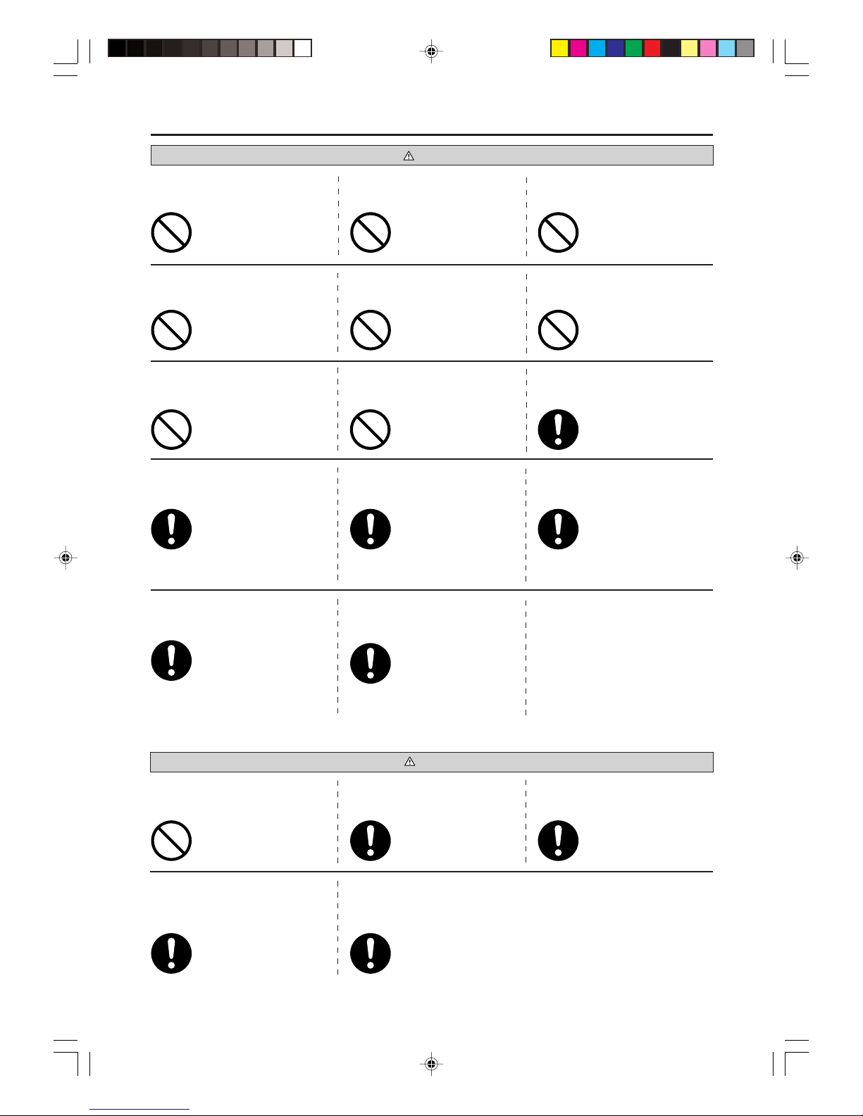
Safety precautions
• Before starting to use the system, please read these “Safety precautions” carefully to ensure proper operation of the system.
• The safety precautions are classified as “ DANGER” and “ CAUTION”. Precautions as shown in the column “ DANGER” indicate
that improper handling could lead to drastic result like death, serious injury, etc. Even precautions as shown in the column “ CAUTION”
might pose a serious problem, depending on the circumstances. Please observe these precautions with great care, since they are essential to your
safety.
• Symbols which appear frequently in the text have the following meaning:
• When you have read this instruction manual, please keep it without missing. If someone else takes over as operator, make certain that the manual
is also passed on to the new operator.
Strictly prohibited Provide proper earthing
Observe instructions with
great care
❚ INSTALLATION PRECAUTIONS
Make sure that the system has been
properly earthed.
Depending on the place of installation, an earth leakage breaker may
be necessary.
Do not install it where flammable gas
may leak.
Make sure to install the drain hose
properly so that all the water is
drained out.
The system is for domestic, residential
etc. use.
The system must be installed by your
dealer or a qualified professional.
If used in severer environments,
such as an engineering workplace,
the equipment may function poorly.
It is not advisable to install the system by yourself, as faulty handling
may cause leakage of water, electric
shock or fire.
Gas leaks may cause fire. If you do not install an earth leak-
age breaker, you may get an electric shock.
Improper installation may lead to
water drop in the room resulting
in wet furniture.
Earth cables should never be
connected to a gas pipe, water
pipe, lightning conductor or telephone earth cable. Incorrect installation of the earth cable may
produce an electric shock.
CAUTIONDANGER
❚ OPERATION PRECAUTIONS
Do not expose yourself to the cooling
air for a long period.
Do not insert anything into the air inlet.
DANGER
The appliance is not intended for use by
persons (including children) with reduced
physical,sensory or mental capabilities,
or lack of experience and knowledge, unless they have been given supervision or
instruction concerning use of the appliance by a person responsible for their
safety.
Store the remote control out of reach of
infants.
This could affect your physical
condition and cause health problems.
Do not place a flammable insecticide
or paint spray near the blower, nor
spray it directly on the system.
Do not handle the switches with wet
hands.
Only use approved fuses.
Do not swing from the indoor unit.
This may cause injury, as the internal fan rotates at high speed.
Use of steel or copper wire instead of an approved fuse is
strictly prohibited, as it may
cause a breakdown or fire.
This may cause an electric
shock.
If the indoor unit falls down,
you may get injured.
This may result in a fire.
CAUTION
Do not wash the air-conditioner with
water.
You should not expose any combustion appliance directly to the air
stream of the air-conditioner.
Children should be supervised to
ensure that they do not play with
the appliance.
The appliance may then work
inadequately.
This could cause an electric
shock.
Do not place anything containing water, like vases, on top of the unit.
The system should only be used for its original purpose and not for anything else like,
for instance, preservation of food, plants or
animals, precision devices or works of art.
Failure to observe this may result in the batteries being swallowed or other accidents.
The system is only intended
for use in ordinary domestic
rooms. Any other use of the
system may damage the quality of food, etc.
Water entering the unit could
damage the insulation and therefore cause an electric shock.
–3–
❚ Safety precautions
CAUTION
❚ PRECAUTIONS FOR RELOCATION OR REPAIRS
DANGER
Do not operate the system without
the air filter.
When you clean the system, stop the
unit and turn off the power supply.
Do not install the system where the airflow direction is aimed directly at
plants or animals.
Do not sit on the outdoor unit nor put
anything on it.
After a long period of use, check the
unit's support structure from time to
time.
Do not place household electrical appliances or household items under
neath the indoor or outdoor units.
Stand firmly on a stepladder or other
stable object when removing the inlet
panel and filters.
Do not touch the aluminum fins on the
air heat exchanger.
Do not place objects near the outdoor unit or allow leaves to gather
around the unit.
Contact your dealer to clean inside the
indoor unit, do not attempt to do by
yourself.
This will damage their health. If the unit falls down or things
drop off it, people could get hurt.
If you do not repair any damage
right away, the unit may fall
down and cause personal injury.
It may result in injury. Condensation falling from the
unit may stain objects and cause
accidents or electrical shock.
It can cause malfunction of the
system due to clogging of the
heat exchanger.
Failure to observe this may result
in injury through insecure objects
toppling over.
Never open the panel while the
internal fan is rotating.
If there are objects or leaves
around the outdoor unit, small
animals may enter unit and contact electrical parts and may
cause a break-down, smoke or
fire.
The use of a non-approved detergent or improper washing method
may damage the unit’s plastic components and cause leaks. Damage,
smoke, or fire may also happen if
the detergent comes in contact with
electrical parts or the unit’s motor.
Consult your dealer for repairs.
If you notice anything abnormal (smell of
burning, etc.), stop the system, turn off
the power supply and consult your
dealer.
In case the air-conditioner is relocated elsewhere, contact your dealer
or a professional fitter.
If the air-conditioner fails to cool or warm the room, it may have a refrigerant
leakage. Contact your dealer.
If refrigerant needs to be added, check with your dealer for proper instructions.
Wrong repairs could cause an
electric shock, fire, etc.
Faulty installation may cause water leakage, electric shock, fire,
etc.
Continued use of the system in abnormal circumstances may result
in malfunctioning, electric shock,
fire, etc.
If the refrigerant comes in contact with the bare skin, it may cause cold injury.
If the refrigerant gas is inhaled excessively, it may cause deterioration of nerve function
like dizziness and headache, or deterioration of heart function like irregular heartbeat and
heart palpitation temporarily. If refrigerant unexpectedly leaks from the unit onto a fan
heater, stove, hotplate or other heat source, harmful gases could be generated.
If you operate the system together
with a combustion appliance, you
must regularly ventilate the indoor air.
Do not control the system with main
power switch.
It can cause fire or water leakage.
In addition, the fan can start unexpectedly, which can cause personal injury.
Insufficient ventilation may
cause accidents due to oxygen
deficiency.
Do not shut off the power supply immediately after stopping the operation.
Wait at least 5 minutes, otherwise
there is a risk of water leakage or
breakdown.
Do not perform any repairs or modifications by yourself. Consult the dealer if
the unit requires repair.
If you repair or modify the unit, it
can cause water leaks, electric
shocks or fire.
Stop the unit and turn off the power
if you hear thunder or there is a
danger of lightning.
It may damage the unit.

–4–
Choice of operations
Features
Page 9
Drying by extracting damp from the room.
Page 9
Cooling by extracting heat from the room.
COOL
DRY
Functioning of microcomputer depends on setting and room temperatures. It dehumidifies while keeping room temperature almost
constant.
Page 8
Automatic selection of operating mode.
Page 9
Fanning by circulating room air.
The Auto mode automatically
selects the operation mode
(COOL or DRY), depending
on the room temperature
when switched on.
AUTOFAN
Page 10
Page 11, 12
There are three timers, for SLEEP, ON and
OFF. They can be set as desired.
Page 13
When using the timer to switch on, the system should become operational shortly before the set time, depending on the room
temperature so that the desired temperature
should be reached at the set time.
Amenity facility
TIMER procedure
• SWING FLAP
Flap moves up and down continuously.
• SWING LOUVER
Louver moves left and right continuously.
• MEMORY FLAP (FLAP OR LOUVER STOPPED)
Once the flap or louver position has been set, the
unit will memorise it and continue in the same position the next time.
Adjustment of
airflow
Page 14
Turning up the power operates the air-conditioner in the power cooling mode.
HIGH POWER mode
Page 14
This is an economic level of operation.
ECONOMY mode
Choice of operations and features
–5–
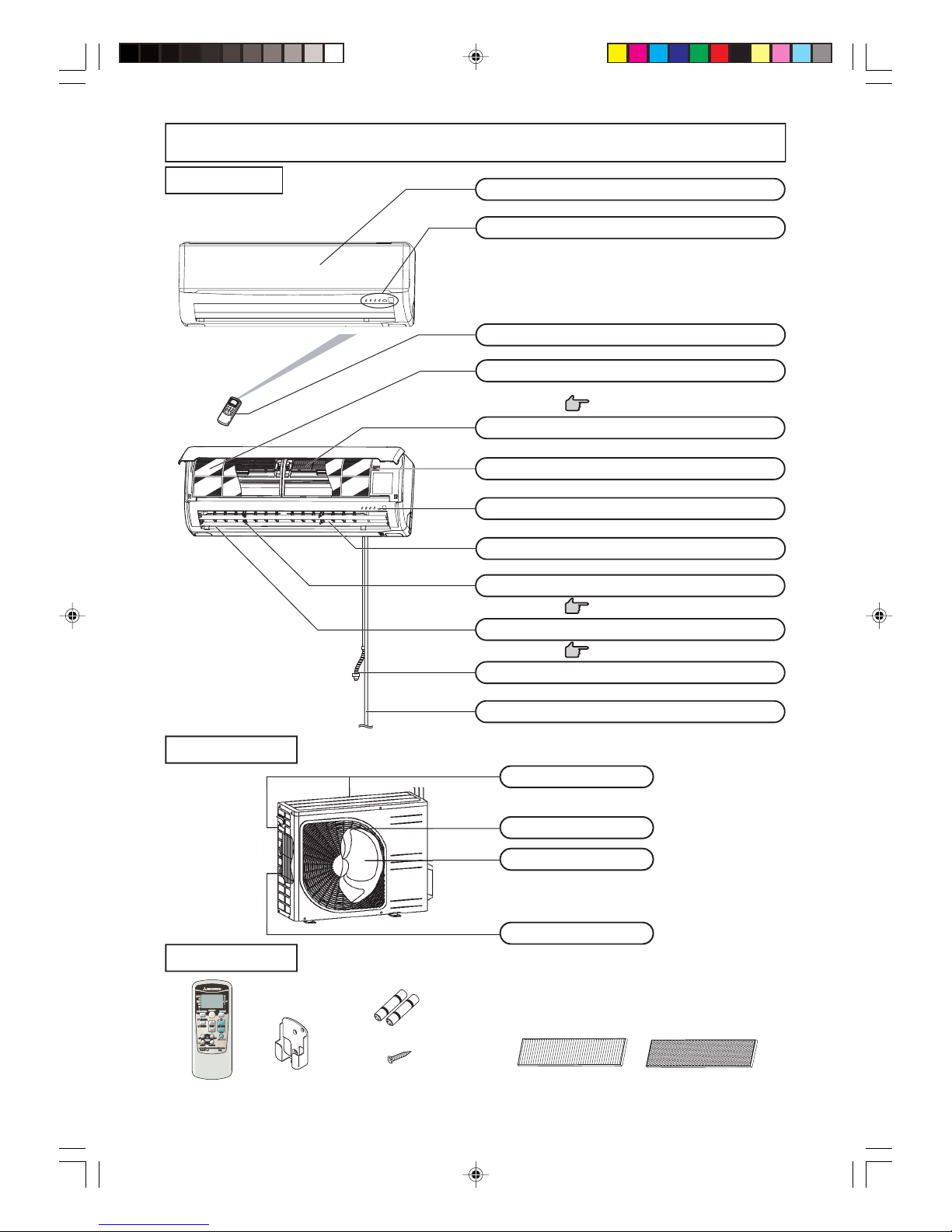
Name of each part and its function
INDOOR UNIT
Draws in the indoor air.
Removes dust or dirt from the inlet air.
Page 18
Drains water from the dehumidified air.
Page 10
Page 10
Air blows out of here.
Accessories
Wireless remote control
Battery (R03
×2)
Wood
screw (Quantity:2)
(for remote control holder mounting)
Wireless remote
control holder
OUTDOOR UNIT
Air inlet panel
Unit indication section and remote control signal receiver
Air-cleaning filter
Air filter
Wireless remote control
Drain hose
Left/right air flow adjustment louver
Up/down air flow direction adjustment flap
Air outlet
Unit operation switch
Room temperature detector
Refrigerant piping connection electric flex
Air outlet
Outdoor unit fan
Heat exchanger
Air inlet
(On side & rear surface)
Photocatalytic washable
deodorizing filter (Orange)
Natural enzyme filter
(Green)
–6–
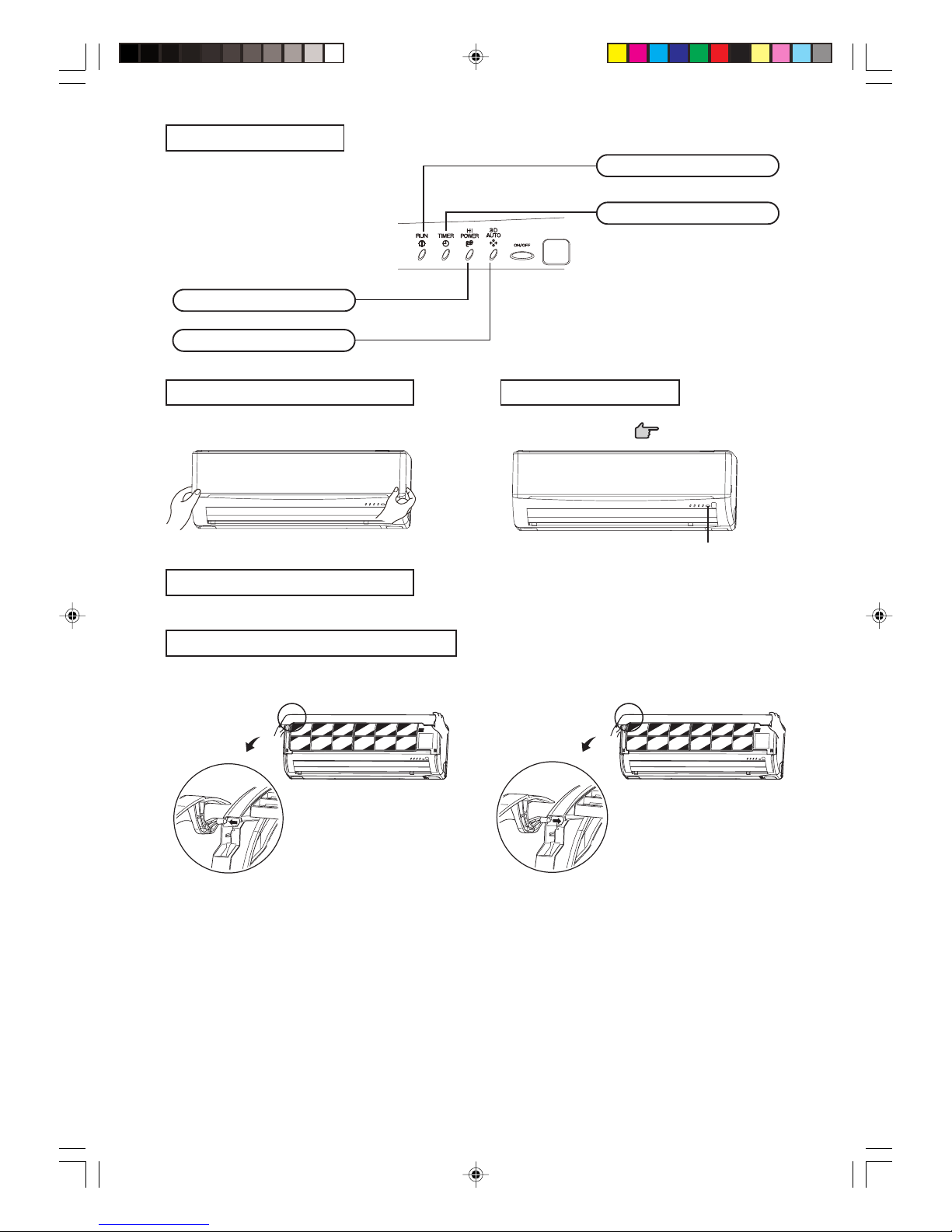
Unit indication section
How to open the air inlet panel
Push both sides evenly and press further lightly at the center.
Place fingers at the recesses on both sides of the panel and pull up the panel
to this side so that it will be opened by about 60 degrees.
Unit ON/OFF button
Secure either the upper or lower edge of the air inlet panel by lightly pushing it
in, and then close the panel.
When removing the air inlet panel for internal cleaning or others, open the
panel by 80 degrees and then pull it to this side.
In emergencies, this button can be used for turning on/off the unit when
remote control is not available.
Page 15
Removal, installation of air inlet panel
3D AUTO light (green)
Illuminates during 3D AUTO operation.
HI POWER light (green)
Illuminates during HIGH POWER operation.
RUN light (green)
Illuminates during operation
and CLEAN operation.
TIMER light (yellow)
Illuminates during TIMER operation.
Unit ON/OFF button
How to close the air inlet panel
–7–
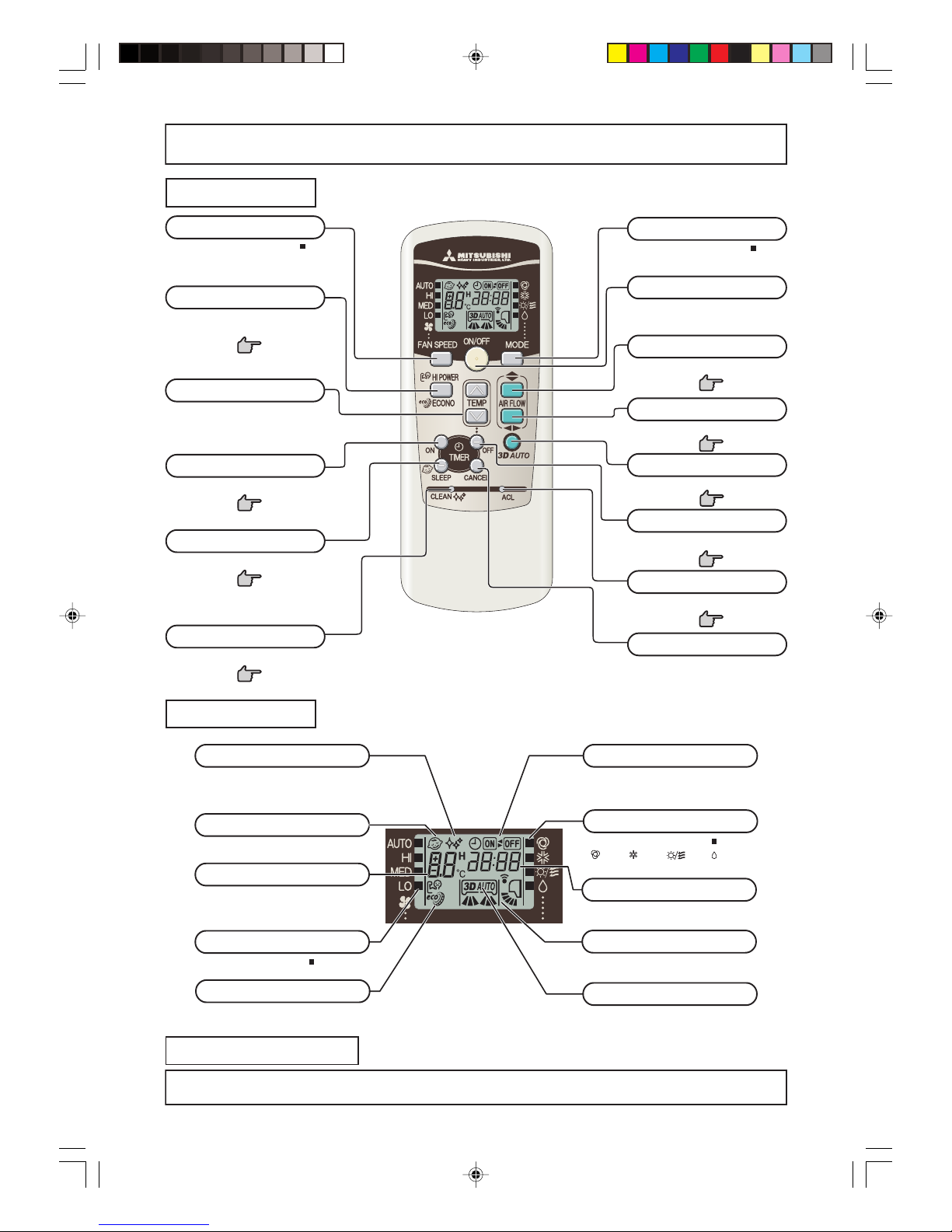
Operation and indication section for remote control
Operation section
FAN SPEED button
Each time the button is pushed, the
indicator is switched over in turn.
•
The above illustration shows all controls, but in practice
only the relevant parts are shown.
OPERATION MODE select button
Each time the button pushed, the
indicator is switched over in turn.
ON/OFF (luminous) button
Press for starting operation, press again
for stopping.
HI POWER/ECONO button
This button changes the HIGH POWER/
ECONOMY mode.
Page 14
AIR FLOW (UP/DOWN) button
This button changes the air flow (up/down) mode.
This button changes the air flow (left/right) mode.
Page 10
SLEEP button
This button changes to SLEEP operation.
Page 11
CLEAN switch
This switch changes the CLEAN mode.
Page 15
ON TIMER button
This button selects ON TIMER operation.
Page 12
AIR FLOW (LEFT/RIGHT) button
Page 10
3D AUTO button
This button sets 3D AUTO operation.
This button cancels the ON timer, OFF
timer, and SLEEP operation.
CANCEL button
RESET switch
Switch for resetting microcomputer and
setting time.
Page 13, 17
Indication section
SLEEP indicator
Indicates during SLEEP operation.
TEMPERATURE indicator
Indicates set temperature.
(Does not indicate temperature when operation
mode is on AUTO)
FAN SPEED indicator
Indicates set air flow rate with lamp.
CLEAN indicator
Indicates during CLEAN operation.
ON/OFF TIMER indicator
Indicates during ON/OFF TIMER operation.
AIR FLOW indicator
Shows selected flap and louver mode.
3D AUTO indicator
Indicates during 3D AUTO operation.
HI POWER/ECONO MODE indicator
Indicates during HIGH POWER/ECONOMY
mode operation.
Transmission procedure
When each button on the remote control is pressed with the remote control pointing towards the air-conditioner unit a signal is transmitted.
When the air-conditioner receives the signal correctly, it will beep.
[
OPERATION MODE indicator
Indicates selected operation with lamp.
(Auto)•(Cool)• (Fan) •(Dry)]
OFF TIMER button
This button selects OFF TIMER operation.
Page 11
TEMPERATURE button
This button sets the room temperature.
(This button changes the present time and
TIMER time.)
TIME indicator
Indicates present time or timer setting time.
Page 10

–8–
■ Each time the button is pressed, the switch over occurs in the following order
–6 → –5 → ............ –1 → ±0 → +1 ............ +6.
When +6 is indicated, even if the button is pressed, the indicator does not change.
■ Each time the button is pressed, the switch over occurs in the following order
+6 → +5 → ............ +1 → ±0 → –1 ............ –6.
When –6 is indicated, even if the button is pressed, the indicator does not change.
About FAN SPEED
■ You can choose the capacity of your air-conditioner when cooling or fan.
Temperature adjustment during AUTO
■
Air temperature adjustment is possible even during automatic operation. There are 6 levels of adjustment possible with the button or the button.
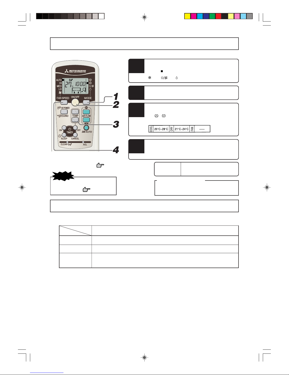
AUTO mode operation procedure
■ Automatically selects the operation mode (COOL, DRY) depending on the room temperature when switched on.
Air flow direction adjustment proce-
dure. Page 10
1
When a change in temperature is desired.
Press the or button.
• Air is not blown out during the opera-
tion.
Page 21
• If you don’t want the AUTO mode program, change
to COOL, DRY or FAN instead of AUTO.
Page 9
AUTO mode can be operated by simply pressing
the ON/OFF button.
To stop: Press the ON/OFF button.
When the unit is not in AUTO mode:
Press MODE button.
Move the [ mark] to the (Auto) position.
Aim the remote control at the air-conditioner.
Press the ON/OFF button.
1
2
When it is a little cold
Press the button.
When it is a little hot
Press the button.
Press the FAN SPEED button.
Move the [ mark] to the desirable fan speed position.
Operation capacity by your choice FAN SPEED
Set automatically by microcomputer AUTO
Powerful operation with high capacity HI
Standard operation MED
Energy-saving operation LO
AUTO HI MED LO
NOTE
–9–
COOL/DRY/FAN mode operation procedure
Air flow direction adjustment procedure.
Page 10
Program changing procedure
Set the new program.
• The operation program can also be set or changed when
the air-conditioner is not in operation.
Aim the remote control at the air-conditioner.
Press the MODE select button.
Move the [ mark] to the desirable operation position.
(Cool), (Fan), (Dry)
Press the ON/OFF button.
Press the TEMP button.
Press or button for the desired temperature.
Standard
4
3
To stop: Press the ON/OFF button.
• Air is not blown out during the operation.
Page 21
NOTE
2
1
Air-conditioner operating conditions
■ Use within the following operational range. Operating outside of this range may result in the protection devices being activated, preventing
the unit from working.
Cooling operation
Outside temperature Approximately 21 to 43 °C
Inside temperature Approximately 21 to 32 °C
Below approximately 80%
The long-term use of the unit with a humidity level exceeding 80% may result in condensation forming on the
surface of the indoor unit, leading to water drips.
Press the FAN SPEED button
Set the fan speed as desired.
Inside humidity
–10–
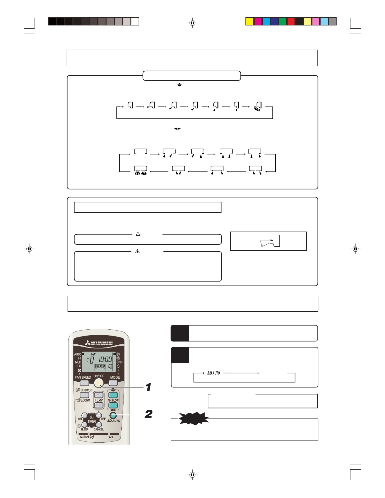
Air flow direction adjustment procedure
Adjusting air flow direction
■ Up/down direction can be adjusted with the AIRFLOW
(UP/DOWN) button on the remote control. Each time when you press this
button the mode changes as follows:
Change to AIRFLOW (UP/DOWN) mode.
(Swing)
(Flap stopped)
■ Left/right direction can be adjusted with the AIRFLOW (LEFT/RIGHT) button on the remote control. Each time when you press this
button the mode changes as follows:
Change to AIRFLOW (LEFT/RIGHT) mode.
(Louver stopped)
(Swing)
MEMORY FLAP (FLAP OR LOUVER STOPPED)
When you press the AIRFLOW (UP/DOWN or LEFT/RIGHT) button once while the flap or
louver is operating, it stops swinging at an angle.Since this angle is memorized in the microcomputer, the flap or louver will automatically be set at this angle when the next operation is started.
DANGER
• Avoid constant airflow to the body for hours on end.
CAUTION
• When in COOL or DRY operation, do not operate for hours on end with the
air flow blowing straight down. Otherwise, condensation may appear on the
outlet grill and drip down.
• Do not try to adjust the flaps and louvers by hand, as the control angle may
change or the flap or louver may not close properly.
(Horizontal
blowing)
COOL, DRY
• Recommended angle of the flap when stopping
3D AUTO operation procedure
2
Press the 3D AUTO button.
Each time the 3D AUTO button is pressed, the indicator is switched
in the order of:
No indication
Fan speed and air flow direction are automatically controlled, allowing the entire room to be efficiently conditioned.
(3D AUTO) (Normal operation)
• 3D AUTO operation is cancelled when you switch the operation program.
• The 3D AUTO light illuminates during 3D AUTO operation.
NOTE
Press the ON/OFF button.
1
Releasing procedure
Press the 3D AUTO button to turn off the 3D AUTO indicator.
 Loading...