

Mitsubishi Heavy Industries SRK05CM, SRK05CM-3, SRK09CM-3, SRK09CM-4, SRK09CM-5 Technical Manual
...
RESIDENTIAL AIR-CONDITIONING
TECHNICAL MANUAL & PARTS LIST
WALL MOUNTED TYPE
RESIDENTIAL AIR-CONDITIONERS
(Split system, air cooled cooling only type)
SRK05CM, 05CM-3
SRK05CMP-3
SRK09CM-3, 09CM-4, 09CM-5
SRK09CMP-3, 09CMP-4
SRK12CM-3, 12CM-4, 12CM-5
Manual No.'13•SRK-T-141
-
1
-
'13•SRK-T-141
TECHNICAL MANUAL

-
2
-
'13•SRK-T-141
'10 • SRK-T-099
CONTENTS
1. SPECIFICATIONS .................................................................................... 4
(2) Outdoor units ...................................................................................... 17
(3) Wireless remote control
...................................................................... 19
........................................................................ 15
(1) Indoor units ......................................................................................... 15
2. EXTERIOR DIMENSIONS
3. ELECTRICAL WIRING ............................................................................. 20
(1) Indoor units ......................................................................................... 20
(2) Outdoor units ...................................................................................... 21
....................................................... 24
5. RANGE OF USAGE & LIMITATIONS
4. PIPING SYSTEM ..................................................................................... 23
............................................................................... 26
6. APPLICATION DATA
7. OUTLINE OF OPERATION CONTROL BY MICROCOMPUTER ........... 40
(6) Timer operation
................................................................................. 43
(5) Flap control ....................................................................................... 43
...................................................... 42(4) Custom cord switching procedure
........................................................................ 42(3) Auto restart function
(2) Unit ON/OFF button
.......................................................................... 42
(1) Operation control function by remote control
..................................... 40
(8) Outline of automatic operation .......................................................... 44
(7) Outline of cooling operation .............................................................. 44
(9) Protective control function
.................................................................. 45
.............................................................................. 46
.................... 47
(4) Troubleshooting procedure (If the air conditioner runs)
(3) Troubleshooting procedure
(If the air conditioner does not run at all)
....... 46
(1) Cautions
............................................................................................ 46
(2) Items to check before troubleshooting ................................................ 46
(5) Self-diagnosis table ............................................................................ 47
(6) Inspection procedures corresponding to detail of trouble ................... 48
8. MAINTENANCE DATA

-
3
-
'13•SRK-T-141
'10 • SRK-T-099
(7)
Phenomenon observed after shortcircuit, wire breakage on sensor
........ 49
■How to read the model name
Example: SRK 05 C
Series code
Cooling only type
Product capacity
Model name SRK : Wall mounted type
SRC : Outdoor unit
MP
(8) How to make sure of wireless remote control ..................................... 50
-
4
-
'13•SRK-T-141
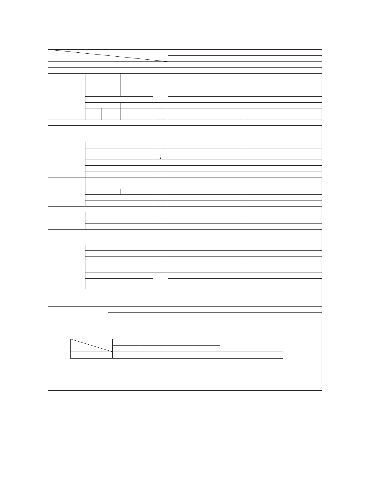
1. SPECIFICATIONS
Model
Item
SRK05CM
Indoor unit SRK05CM Outdoor unit SRC05CM
Cooling capacity (1) W 1500
Power supply 1 Phase, 220V, 50Hz
Operation
data (1)
Power
consumption
Cooling kW 0.42
Running
current
Cooling
A
2.0
Inrush current 9.5
COP Cooling 3.57
Noise
level
Cooling Sound level dB(A) 42 47
Exterior dimensions (Height x Width x Depth) mm 262 x 615 x 210 435 x 645 (+50) x 275
Exterior appearance
(Munsell color)
Fine snow
(8.0Y 9.3/0.1) near equivalent
Stucco white
(4.2Y 7.5/1.1) near equivalent
Net weight kg 6 19
Refrigerant
equipment
Compressor type & Q'ty — RMC201A009 (Rotary type) x 1
Motor (Starting method) kW — 0.35 (PSC)
Refrigerant oil 0.29 (SUNISO 4GSI or ATMOS NM56M)
Refrigerant (3) kg R22 0.40 (Pre-Charged up to the piping length of 7.5m)
Heat exchanger Louver fins & inner grooved tubing Louver fins & inner grooved tubing
Refrigerant control Capillary tubes
Air handling
equipment
Fan type & Q'ty Cross flow fan x 1 Propeller fan x 1
Motor W 17 22
Air flow Cooling m3/min 8.5 23.0
Fresh air intake Not possible —
Air filter, Quality / Quantity Polypropylene net (washable) x 1 —
Shock & vibration absorber — Cushion rubber (for compressor)
Operation
control
Operation switch Wireless-Remote control —
Room temperature control Microcomputer thermostat —
Operation Display RUN : Green, TIMER : Yellow
Safety devices
Compressor overheat protection, Overcurrent protection,
Frost protection, Serial signal error protection, Indoor fan motor error protection,
Cooling overload protection
Installation
data
Refrigerant piping size (O.D) mm Liquid line: φ6.35 (1/4") Gas line: φ9.52 (3/8")
Connecting method Flare connecting
Attached length of piping m
Liquid line : 0.46
Gas line : 0.40
—
Insulation for piping Necessary (Both sides), independent
Refrigerant line (one way) length
m
Max. 15
Vertical height difference between
outdoor unit and indoor unit
Max.5 (Outdoor unit is higher)
Max.5 (Outdoor unit is lower)
Drain hose Connectable (VP 16) —
Power cable —
Recommended breaker size A 10
Connection wiring
Size x Core number 1.5mm2 x 3 cores (Including earth cable)
Connecting method Terminal block (Screw fixing type)
Accessories (included) Mounting kit
Option parts —
Note (1) The data are measured at the following conditions.
Item
Operation
Indoor air temperature Outdoor air temperature
Standards
DB WB DB WB
Cooling 27˚C 19˚C 35˚C 24˚C JIS C 9612, TISI 1155, 2134, 812
(2) This air-conditioner is manufactured and tested in conformity with the TISI.
(3) The operation data are applied to the 220V districts.
(4) The refrigerant quantity to be charged includes the refrigerant in 7.5m connecting piping.
(Purging is not required even for the short piping.)
If the piping length is 7.5m to 15m, additional refrigerant is 10g per each 1m longer than 7.5m.
The pipe length is 7.5m.

-
5
-
'13•SRK-T-141
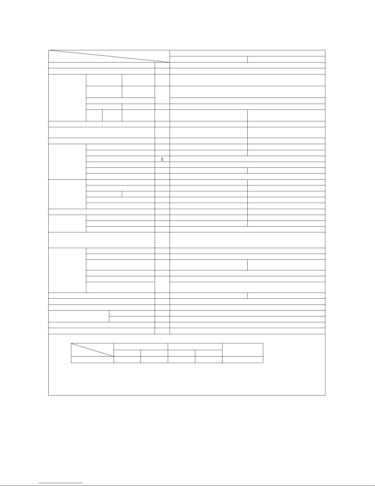
Model
Item
SRK05CM-3
Indoor unit SRK05CM-3 Outdoor unit SRC05CM-3
Cooling capacity (1) W 1465
Power supply 1 Phase, 220 - 240V, 50Hz
Operation
data (1)
Power
consumption
Cooling kW 0.375
Running
current
Cooling
A
1.8
Inrush current 9.5
COP Cooling 3.91
Noise
level
Cooling Sound level dB(A) 42 48
Exterior dimensions (Height x Width x Depth) mm 262 x 615 x 210 435 x 645 (+50) x 275
Exterior appearance
(Munsell color)
Fine snow
(8.0Y 9.3/0.1) near equivalent
Stucco white
(4.2Y 7.5/1.1) near equivalent
Net weight kg 6 20
Refrigerant
equipment
Compressor type & Q'ty — RMC201A055 (Rotary type) x 1
Motor (Starting method) kW — 0.35 (PSC)
Refrigerant oil 0.23 (SUNISO 4GSI or ATMOS NM56M)
Refrigerant (3) kg R22 0.45 (Pre-Charged up to the piping length of 5.0m)
Heat exchanger Louver fins & inner grooved tubing Louver fins & inner grooved tubing
Refrigerant control Capillary tubes
Air handling
equipment
Fan type & Q'ty Cross flow fan x 1 Propeller fan x 1
Motor W 17 22
Air flow Cooling m3/min 8.5 23.0
Fresh air intake Not possible —
Air filter, Quality / Quantity Polypropylene net (washable) x 1 —
Shock & vibration absorber — Cushion rubber (for compressor)
Operation
control
Operation switch Wireless-Remote control —
Room temperature control Microcomputer thermostat —
Operation Display RUN : Green, TIMER : Yellow
Safety devices
Compressor overheat protection, Overcurrent protection,
Frost protection, Serial signal error protection, Indoor fan motor error protection,
Cooling overload protection
Installation
data
Refrigerant piping size (O.D) mm Liquid line: φ6.35 (1/4") Gas line: φ9.52 (3/8")
Connecting method Flare connecting
Attached length of piping m
Liquid line : 0.46
Gas line : 0.40
—
Insulation for piping Necessary (Both sides), independent
Refrigerant line (one way) length
m
Max. 15
Vertical height difference between
outdoor unit and indoor unit
Max.5 (Outdoor unit is higher)
Max.5 (Outdoor unit is lower)
Drain hose Connectable (VP 16) —
Power cable —
Recommended breaker size A 10
Connection wiring
Size x Core number 1.5mm2 x 3 cores (Including earth cable)
Connecting method Terminal block (Screw fixing type)
Accessories (included) Mounting kit
Option parts —
Note (1) The data are measured at the following conditions.
Item
Operation
Indoor air temperature Outdoor air temperature
Standards
DB WB DB WB
Cooling 27˚C 19˚C 35˚C 24˚C ISO-T1, JIS C 9612
(2) This air-conditioner is manufactured and tested in conformity with the ISO.
(3) The operation data are applied to the 220V districts.
(4) The refrigerant quantity to be charged includes the refrigerant in 5.0m connecting piping.
(Purging is not required even for the short piping.)
If the piping length is 5m to 15m, additional refrigerant is 10g per each 1m longer than 5m.
The pipe length is 5.0m.

-
6
-
'13•SRK-T-141
Model
Item
SRK05CMP-3
Indoor unit SRK05CMP-3 Outdoor unit SRC05CMP-3
Cooling capacity (1) W 1465
Power supply 1 Phase, 220 - 240V, 50Hz
Operation
data (1)
Power
consumption
Cooling kW 0.49
Running
current
Cooling
A
2.3 / 2.2
Inrush current 9.5
COP Cooling 2.99
Noise
level
Cooling Sound level dB(A) 42 47
Exterior dimensions (Height x Width x Depth) mm 262 x 615 x 210 435 x 645 (+50) x 275
Exterior appearance
(Munsell color)
Fine snow
(8.0Y 9.3/0.1) near equivalent
Stucco white
(4.2Y 7.5/1.1) near equivalent
Net weight kg 6 19
Refrigerant
equipment
Compressor type & Q'ty — RMC201A009 (Rotary type) x 1
Motor (Starting method) kW — 0.35 (PSC)
Refrigerant oil 0.29 (SUNISO 4GSI or ATMOS NM56M)
Refrigerant (3) kg R22 0.34 (Pre-Charged up to the piping length of 5.0m)
Heat exchanger Louver fins & inner grooved tubing Louver fins & inner grooved tubing
Refrigerant control Capillary tubes
Air handling
equipment
Fan type & Q'ty Cross flow fan x 1 Propeller fan x 1
Motor W 17 22
Air flow Cooling m3/min 8.5 20.0
Fresh air intake Not possible —
Air filter, Quality / Quantity Polypropylene net (washable) x 1 —
Shock & vibration absorber — Cushion rubber (for compressor)
Operation
control
Operation switch Wireless-Remote control —
Room temperature control Microcomputer thermostat —
Operation Display RUN : Green, TIMER : Yellow
Safety devices
Compressor overheat protection, Overcurrent protection,
Frost protection, Serial signal error protection, Indoor fan motor error protection,
Cooling overload protection
Installation
data
Refrigerant piping size (O.D) mm Liquid line: φ6.35 (1/4") Gas line: φ9.52 (3/8")
Connecting method Flare connecting
Attached length of piping m
Liquid line : 0.46
Gas line : 0.40
—
Insulation for piping Necessary (Both sides), independent
Refrigerant line (one way) length
m
Max. 15
Vertical height difference between
outdoor unit and indoor unit
Max.5 (Outdoor unit is higher)
Max.5 (Outdoor unit is lower)
Drain hose Connectable (VP 16) —
Power cable —
Recommended breaker size A 10
Connection wiring
Size x Core number 1.5mm2 x 3 cores (Including earth cable)
Connecting method Terminal block (Screw fixing type)
Accessories (included) Mounting kit
Option parts —
Note (1) The data are measured at the following conditions.
Item
Operation
Indoor air temperature Outdoor air temperature
Standards
DB WB DB WB
Cooling 27˚C 19˚C 35˚C 24˚C ISO-T1, JIS C 9612
(2) This air-conditioner is manufactured and tested in conformity with the ISO.
(3) The operation data are applied to the 220 / 230V districts respectively.
(4) The refrigerant quantity to be charged includes the refrigerant in 5.0m connecting piping.
(Purging is not required even for the short piping.)
If the piping length is 5m to 15m, additional refrigerant is 10g per each 1m longer than 5m.
The pipe length is 5.0m.
-
7
-
'13•SRK-T-141
Model
Item
SRK09CM-3
Indoor unit SRK09CM-3 Outdoor unit SRC09CM-3
Cooling capacity (1) W 2638
Power supply 1 Phase, 220 - 240V, 50Hz
Operation
data (1)
Power
consumption
Cooling kW 0.90
Running
current
Cooling
A
4.2 / 4.0
Inrush current 21.0
COP Cooling 2.93
Noise
level
Cooling Sound level dB(A) 43 50
Exterior dimensions (Height x Width x Depth) mm 262 x 615 x 210 435 x 645 (+50) x 275
Exterior appearance
(Munsell color)
Fine snow
(8.0Y 9.3/0.1) near equivalent
Stucco white
(4.2Y 7.5/1.1) near equivalent
Net weight kg 6 22.5
Refrigerant
equipment
Compressor type & Q'ty — RMC201A054 (Rotary type) x 1
Motor (Starting method) kW — 0.7 (PSC)
Refrigerant oil 0.28 (SUNISO 4GSI or ATMOS NM56M)
Refrigerant (3) kg R22 0.45 (Pre-Charged up to the piping length of 5.0m)
Heat exchanger Louver fins & inner grooved tubing Louver fins & inner grooved tubing
Refrigerant control Capillary tubes
Air handling
equipment
Fan type & Q'ty Cross flow fan x 1 Propeller fan x 1
Motor W 17 22
Air flow Cooling m3/min 9.0 23.0
Fresh air intake Not possible —
Air filter, Quality / Quantity Polypropylene net (washable) x 1 —
Shock & vibration absorber — Cushion rubber (for compressor)
Operation
control
Operation switch Wireless-Remote control —
Room temperature control Microcomputer thermostat —
Operation Display RUN : Green, TIMER : Yellow
Safety devices
Compressor overheat protection, Overcurrent protection,
Frost protection, Serial signal error protection, Indoor fan motor error protection,
Cooling overload protection
Installation
data
Refrigerant piping size (O.D) mm Liquid line: φ6.35 (1/4") Gas line: φ9.52 (3/8")
Connecting method Flare connecting
Attached length of piping m
Liquid line : 0.46
Gas line : 0.40
—
Insulation for piping Necessary (Both sides), independent
Refrigerant line (one way) length
m
Max. 15
Vertical height difference between
outdoor unit and indoor unit
Max.5 (Outdoor unit is higher)
Max.5 (Outdoor unit is lower)
Drain hose Connectable (VP 16) —
Power cable —
Recommended breaker size A 10
Connection wiring
Size x Core number 1.5mm2 x 3 cores (Including earth cable)
Connecting method Terminal block (Screw fixing type)
Accessories (included) Mounting kit
Option parts —
Note (1) The data are measured at the following conditions.
Item
Operation
Indoor air temperature Outdoor air temperature
Standards
DB WB DB WB
Cooling 27˚C 19˚C 35˚C 24˚C ISO-T1, JIS C 9612
(2) This air-conditioner is manufactured and tested in conformity with the ISO.
(3) The operation data are applied to the 220 / 230V districts respectively.
(4) The refrigerant quantity to be charged includes the refrigerant in 5.0m connecting piping.
(Purging is not required even for the short piping.)
If the piping length is 5m to 15m, additional refrigerant is 10g per each 1m longer than 5m.
The pipe length is 5.0m.

-
8
-
'13•SRK-T-141
Model
Item
SRK09CM-4
Indoor unit SRK09CM-4 Outdoor unit SRC09CM-4
Cooling capacity (1) W 2638
Power supply 1 Phase, 220 - 240V, 50Hz
Operation
data (1)
Power
consumption
Cooling kW 0.90
Running
current
Cooling
A
4.2 / 4.0
Inrush current 21.0
COP Cooling 2.93
Noise
level
Cooling Sound level dB(A) 43 50
Exterior dimensions (Height x Width x Depth) mm 262 x 615 x 210 435 x 645 (+50) x 275
Exterior appearance
(Munsell color)
Fine snow
(8.0Y 9.3/0.1) near equivalent
Stucco white
(4.2Y 7.5/1.1) near equivalent
Net weight kg 6 22.5
Refrigerant
equipment
Compressor type & Q'ty — RMC201A054 (Rotary type) x 1
Motor (Starting method) kW — 0.7 (PSC)
Refrigerant oil 0.28 (SUNISO 4GSI or ATMOS NM56M)
Refrigerant (3) kg R22 0.45 (Pre-Charged up to the piping length of 5.0m)
Heat exchanger Louver fins & inner grooved tubing Louver fins & inner grooved tubing
Refrigerant control Capillary tubes
Air handling
equipment
Fan type & Q'ty Cross flow fan x 1 Propeller fan x 1
Motor W 17 22
Air flow Cooling m3/min 9.0 23.0
Fresh air intake Not possible —
Air filter, Quality / Quantity Polypropylene net (washable) x 1 —
Shock & vibration absorber — Cushion rubber (for compressor)
Operation
control
Operation switch Wireless-Remote control —
Room temperature control Microcomputer thermostat —
Operation Display RUN : Green, TIMER : Yellow
Safety devices
Compressor overheat protection, Overcurrent protection,
Frost protection, Serial signal error protection, Indoor fan motor error protection,
Cooling overload protection
Installation
data
Refrigerant piping size (O.D) mm Liquid line: φ6.35 (1/4") Gas line: φ9.52 (3/8")
Connecting method Flare connecting
Attached length of piping m
Liquid line : 0.46
Gas line : 0.40
—
Insulation for piping Necessary (Both sides), independent
Refrigerant line (one way) length
m
Max. 15
Vertical height difference between
outdoor unit and indoor unit
Max.5 (Outdoor unit is higher)
Max.5 (Outdoor unit is lower)
Drain hose Connectable (VP 16) —
Power cable —
Recommended breaker size A 10
Connection wiring
Size x Core number 1.5mm2 x 3 cores (Including earth cable)
Connecting method Terminal block (Screw fixing type)
Accessories (included) Mounting kit
Option parts —
Note (1) The data are measured at the following conditions.
Item
Operation
Indoor air temperature Outdoor air temperature
Standards
DB WB DB WB
Cooling 27˚C 19˚C 35˚C 24˚C ISO-T1, JIS C 9612
(2) This air-conditioner is manufactured and tested in conformity with the ISO.
(3) The operation data are applied to the 220 / 230V districts respectively.
(4) The refrigerant quantity to be charged includes the refrigerant in 5.0m connecting piping.
(Purging is not required even for the short piping.)
If the piping length is 5m to 15m, additional refrigerant is 10g per each 1m longer than 5m.
The pipe length is 5.0m.

-
9
-
'13•SRK-T-141
Model
Item
SRK09CM-5
Indoor unit SRK09CM-5 Outdoor unit SRC09CM-5
Cooling capacity (1) W 2638
Power supply 1 Phase, 220 - 240V, 50Hz
Operation
data (1)
Power
consumption
Cooling kW 0.90
Running
current
Cooling
A
4.2 / 4.0
Inrush current 21.0
COP Cooling 2.93
Noise
level
Cooling Sound level dB(A) 43 50
Exterior dimensions (Height x Width x Depth) mm 262 x 615 x 210 435 x 645 (+50) x 275
Exterior appearance
(Munsell color)
Fine snow
(8.0Y 9.3/0.1) near equivalent
Stucco white
(4.2Y 7.5/1.1) near equivalent
Net weight kg 6 22.5
Refrigerant
equipment
Compressor type & Q'ty — RMC201A054 (Rotary type) x 1
Motor (Starting method) kW — 0.7 (PSC)
Refrigerant oil 0.28 (SUNISO 4GSI or ATMOS NM56M)
Refrigerant (3) kg R22 0.45 (Pre-Charged up to the piping length of 5.0m)
Heat exchanger Louver fins & inner grooved tubing Louver fins & inner grooved tubing
Refrigerant control Capillary tubes
Air handling
equipment
Fan type & Q'ty Cross flow fan x 1 Propeller fan x 1
Motor W 17 22
Air flow Cooling m3/min 9.0 23.0
Fresh air intake Not possible —
Air filter, Quality / Quantity Polypropylene net (washable) x 1 —
Shock & vibration absorber — Cushion rubber (for compressor)
Operation
control
Operation switch Wireless-Remote control —
Room temperature control Microcomputer thermostat —
Operation Display RUN : Green, TIMER : Yellow
Safety devices
Compressor overheat protection, Overcurrent protection,
Frost protection, Serial signal error protection, Indoor fan motor error protection,
Cooling overload protection
Installation
data
Refrigerant piping size (O.D) mm Liquid line: φ6.35 (1/4") Gas line: φ9.52 (3/8")
Connecting method Flare connecting
Attached length of piping m
Liquid line : 0.46
Gas line : 0.40
—
Insulation for piping Necessary (Both sides), independent
Refrigerant line (one way) length
m
Max. 15
Vertical height difference between
outdoor unit and indoor unit
Max.5 (Outdoor unit is higher)
Max.5 (Outdoor unit is lower)
Drain hose Connectable (VP 16) —
Power cable —
Recommended breaker size A 10
Connection wiring
Size x Core number 1.5mm2 x 3 cores (Including earth cable)
Connecting method Terminal block (Screw fixing type)
Accessories (included) Mounting kit
Option parts —
Note (1) The data are measured at the following conditions.
Item
Operation
Indoor air temperature Outdoor air temperature
Standards
DB WB DB WB
Cooling 27˚C 19˚C 35˚C 24˚C ISO-T1, JIS C 9612
(2) This air-conditioner is manufactured and tested in conformity with the ISO.
(3) The operation data are applied to the 220 / 230V districts respectively.
(4) The refrigerant quantity to be charged includes the refrigerant in 5.0m connecting piping.
(Purging is not required even for the short piping.)
If the piping length is 5m to 15m, additional refrigerant is 10g per each 1m longer than 5m.
The pipe length is 5.0m.

-
10
-
'13•SRK-T-141
Model
Item
SRK09CMP-3
Indoor unit SRK09CMP-3 Outdoor unit SRC09CMP-3
Cooling capacity (1) W 2500
Power supply 1 Phase, 220 - 240V, 50Hz
Operation
data (1)
Power
consumption
Cooling kW 0.925
Running
current
Cooling
A
4.7 / 4.6
Inrush current 21.0
COP Cooling 2.70
Noise
level
Cooling Sound level dB(A) 43 50
Exterior dimensions (Height x Width x Depth) mm 262 x 615 x 210 435 x 645 (+50) x 275
Exterior appearance
(Munsell color)
Fine snow
(8.0Y 9.3/0.1) near equivalent
Stucco white
(4.2Y 7.5/1.1) near equivalent
Net weight kg 6 22
Refrigerant
equipment
Compressor type & Q'ty — RMC201A054 (Rotary type) x 1
Motor (Starting method) kW — 0.7 (PSC)
Refrigerant oil 0.28 (SUNISO 4GSI or ATMOS NM56M)
Refrigerant (3) kg R22 0.41 (Pre-Charged up to the piping length of 5.0m)
Heat exchanger Louver fins & inner grooved tubing Louver fins & inner grooved tubing
Refrigerant control Capillary tubes
Air handling
equipment
Fan type & Q'ty Cross flow fan x 1 Propeller fan x 1
Motor W 17 22
Air flow Cooling m3/min 9.0 23.0
Fresh air intake Not possible —
Air filter, Quality / Quantity Polypropylene net (washable) x 1 —
Shock & vibration absorber — Cushion rubber (for compressor)
Operation
control
Operation switch Wireless-Remote control —
Room temperature control Microcomputer thermostat —
Operation Display RUN : Green, TIMER : Yellow
Safety devices
Compressor overheat protection, Overcurrent protection,
Frost protection, Serial signal error protection, Indoor fan motor error protection,
Cooling overload protection
Installation
data
Refrigerant piping size (O.D) mm Liquid line: φ6.35 (1/4") Gas line: φ9.52 (3/8")
Connecting method Flare connecting
Attached length of piping m
Liquid line : 0.46
Gas line : 0.40
—
Insulation for piping Necessary (Both sides), independent
Refrigerant line (one way) length
m
Max. 15
Vertical height difference between
outdoor unit and indoor unit
Max.5 (Outdoor unit is higher)
Max.5 (Outdoor unit is lower)
Drain hose Connectable (VP 16) —
Power cable —
Recommended breaker size A 10
Connection wiring
Size x Core number 1.5mm2 x 3 cores (Including earth cable)
Connecting method Terminal block (Screw fixing type)
Accessories (included) Mounting kit
Option parts —
Note (1) The data are measured at the following conditions.
Item
Operation
Indoor air temperature Outdoor air temperature
Standards
DB WB DB WB
Cooling 27˚C 19˚C 35˚C 24˚C ISO-T1, JIS C 9612
(2) This air-conditioner is manufactured and tested in conformity with the ISO.
(3) The operation data are applied to the 220 / 230V districts respectively.
(4) The refrigerant quantity to be charged includes the refrigerant in 5.0m connecting piping.
(Purging is not required even for the short piping.)
If the piping length is 5m to 15m, additional refrigerant is 10g per each 1m longer than 5m.
The pipe length is 5.0m.

-
11
-
'13•SRK-T-141
Model
Item
SRK09CMP-4
Indoor unit SRK09CMP-4 Outdoor unit SRC09CMP-4
Cooling capacity (1) W 2500
Power supply 1 Phase, 220 - 240V, 50Hz
Operation
data (1)
Power
consumption
Cooling kW 0.925
Running
current
Cooling
A
4.7 / 4.6
Inrush current 21.0
COP Cooling 2.70
Noise
level
Cooling Sound level dB(A) 43 50
Exterior dimensions (Height x Width x Depth) mm 262 x 615 x 210 435 x 645 (+50) x 275
Exterior appearance
(Munsell color)
Fine snow
(8.0Y 9.3/0.1) near equivalent
Stucco white
(4.2Y 7.5/1.1) near equivalent
Net weight kg 6 22
Refrigerant
equipment
Compressor type & Q'ty — RMC201A054 (Rotary type) x 1
Motor (Starting method) kW — 0.7 (PSC)
Refrigerant oil 0.28 (SUNISO 4GSI or ATMOS NM56M)
Refrigerant (3) kg R22 0.41 (Pre-Charged up to the piping length of 5.0m)
Heat exchanger Louver fins & inner grooved tubing Louver fins & inner grooved tubing
Refrigerant control Capillary tubes
Air handling
equipment
Fan type & Q'ty Cross flow fan x 1 Propeller fan x 1
Motor W 17 22
Air flow Cooling m3/min 9.0 23.0
Fresh air intake Not possible —
Air filter, Quality / Quantity Polypropylene net (washable) x 1 —
Shock & vibration absorber — Cushion rubber (for compressor)
Operation
control
Operation switch Wireless-Remote control —
Room temperature control Microcomputer thermostat —
Operation Display RUN : Green, TIMER : Yellow
Safety devices
Compressor overheat protection, Overcurrent protection,
Frost protection, Serial signal error protection, Indoor fan motor error protection,
Cooling overload protection
Installation
data
Refrigerant piping size (O.D) mm Liquid line: φ6.35 (1/4") Gas line: φ9.52 (3/8")
Connecting method Flare connecting
Attached length of piping m
Liquid line : 0.46
Gas line : 0.40
—
Insulation for piping Necessary (Both sides), independent
Refrigerant line (one way) length
m
Max. 15
Vertical height difference between
outdoor unit and indoor unit
Max.5 (Outdoor unit is higher)
Max.5 (Outdoor unit is lower)
Drain hose Connectable (VP 16) —
Power cable —
Recommended breaker size A 10
Connection wiring
Size x Core number 1.5mm2 x 3 cores (Including earth cable)
Connecting method Terminal block (Screw fixing type)
Accessories (included) Mounting kit
Option parts —
Note (1) The data are measured at the following conditions.
Item
Operation
Indoor air temperature Outdoor air temperature
Standards
DB WB DB WB
Cooling 27˚C 19˚C 35˚C 24˚C ISO-T1, JIS C 9612
(2) This air-conditioner is manufactured and tested in conformity with the ISO.
(3) The operation data are applied to the 220 / 230V districts respectively.
(4) The refrigerant quantity to be charged includes the refrigerant in 5.0m connecting piping.
(Purging is not required even for the short piping.)
If the piping length is 5m to 15m, additional refrigerant is 10g per each 1m longer than 5m.
The pipe length is 5.0m.

-
12
-
'13•SRK-T-141
Model
Item
SRK12CM-3
Indoor unit SRK12CM-3 Outdoor unit SRC12CM-3
Cooling capacity (1) W 3517
Power supply 1 Phase, 220 - 240V, 50Hz
Operation
data (1)
Power
consumption
Cooling kW 1.09
Running
current
Cooling
A
5.1
Inrush current 25.0
COP Cooling 3.23
Noise
level
Cooling Sound level dB(A) 43 50
Exterior dimensions (Height x Width x Depth) mm 262 x 769 x 210 540 x 780 (+62) x 290
Exterior appearance
(Munsell color)
Fine snow
(8.0Y 9.3/0.1) near equivalent
Stucco white
(4.2Y 7.5/1.1) near equivalent
Net weight kg 7 29
Refrigerant
equipment
Compressor type & Q'ty — RMC201A056 (Rotary type) x 1
Motor (Starting method) kW — 0.92 (PSC)
Refrigerant oil 0.38 (SUNISO 4GSI or ATMOS NM56)
Refrigerant (3) kg R22 0.58 (Pre-Charged up to the piping length of 5.0m)
Heat exchanger Louver fins & inner grooved tubing Louver fins & inner grooved tubing
Refrigerant control Capillary tubes
Air handling
equipment
Fan type & Q'ty Cross flow fan x 1 Propeller fan x 1
Motor W 17 25
Air flow Cooling m3/min 10.0 32.0
Fresh air intake Not possible —
Air filter, Quality / Quantity Polypropylene net (washable) x 1 —
Shock & vibration absorber — Cushion rubber (for compressor)
Operation
control
Operation switch Wireless-Remote control —
Room temperature control Microcomputer thermostat —
Operation Display RUN : Green, TIMER : Yellow
Safety devices
Compressor overheat protection, Overcurrent protection,
Frost protection, Serial signal error protection, Indoor fan motor error protection,
Cooling overload protection
Installation
data
Refrigerant piping size (O.D) mm Liquid line :φ6.35 (1/4") Gas line :φ12.7 (1/2")
Connecting method Flare connecting
Attached length of piping m
Liquid line : 0.45
Gas line : 0.41
—
Insulation for piping Necessary (Both sides), independent
Refrigerant line (one way) length
m
Max. 15
Vertical height difference between
outdoor unit and indoor unit
Max.5 (Outdoor unit is higher)
Max.5 (Outdoor unit is lower)
Drain hose Connectable (VP 16) —
Power cable —
Recommended breaker size A 15
Connection wiring
Size x Core number 1.5mm2 x 3 cores (Including earth cable)
Connecting method Terminal block (Screw fixing type)
Accessories (included) Mounting kit
Option parts —
Note (1) The data are measured at the following conditions.
Item
Operation
Indoor air temperature Outdoor air temperature
Standards
DB WB DB WB
Cooling 27˚C 19˚C 35˚C 24˚C ISO-T1, JIS C 9612
(2) This air-conditioner is manufactured and tested in conformity with the ISO.
(3) The operation data are applied to the 220V districts.
(4) The refrigerant quantity to be charged includes the refrigerant in 5.0m connecting piping.
(Purging is not required even for the short piping.)
If the piping length is 5m to 15m, additional refrigerant is 10g per each 1m longer than 5m.
The pipe length is 5.0m.

-
13
-
'13•SRK-T-141
Model
Item
SRK12CM-4
Indoor unit SRK12CM-4 Outdoor unit SRC12CM-4
Cooling capacity (1) W 3517
Power supply 1 Phase, 220 - 240V, 50Hz
Operation
data (1)
Power
consumption
Cooling kW 1.09 / 1.11
Running
current
Cooling
A
5.1 / 5.0
Inrush current 25.0
COP Cooling 3.23 / 3.17
Noise
level
Cooling Sound level dB(A) 43 50 / 51
Exterior dimensions (Height x Width x Depth) mm 262 x 769 x 210 540 x 780 (+62) x 290
Exterior appearance
(Munsell color)
Fine snow
(8.0Y 9.3/0.1) near equivalent
Stucco white
(4.2Y 7.5/1.1) near equivalent
Net weight kg 7 29
Refrigerant
equipment
Compressor type & Q'ty — RMC201A056 (Rotary type) x 1
Motor (Starting method) kW — 0.92 (PSC)
Refrigerant oil 0.38 (SUNISO 4GSI or ATMOS NM56)
Refrigerant (3) kg R22 0.58 (Pre-Charged up to the piping length of 5.0m)
Heat exchanger Louver fins & inner grooved tubing Louver fins & inner grooved tubing
Refrigerant control Capillary tubes
Air handling
equipment
Fan type & Q'ty Cross flow fan x 1 Propeller fan x 1
Motor W 17 25
Air flow Cooling m3/min 10.0 32.0
Fresh air intake Not possible —
Air filter, Quality / Quantity Polypropylene net (washable) x 1 —
Shock & vibration absorber — Cushion rubber (for compressor)
Operation
control
Operation switch Wireless-Remote control —
Room temperature control Microcomputer thermostat —
Operation Display RUN : Green, TIMER : Yellow
Safety devices
Compressor overheat protection, Overcurrent protection,
Frost protection, Serial signal error protection, Indoor fan motor error protection,
Cooling overload protection
Installation
data
Refrigerant piping size (O.D) mm Liquid line :φ6.35 (1/4") Gas line :φ12.7 (1/2")
Connecting method Flare connecting
Attached length of piping m
Liquid line : 0.45
Gas line : 0.41
—
Insulation for piping Necessary (Both sides), independent
Refrigerant line (one way) length
m
Max. 15
Vertical height difference between
outdoor unit and indoor unit
Max.5 (Outdoor unit is higher)
Max.5 (Outdoor unit is lower)
Drain hose Connectable (VP 16) —
Power cable —
Recommended breaker size A 15
Connection wiring
Size x Core number 1.5mm2 x 3 cores (Including earth cable)
Connecting method Terminal block (Screw fixing type)
Accessories (included) Mounting kit
Option parts —
Note (1) The data are measured at the following conditions.
Item
Operation
Indoor air temperature Outdoor air temperature
Standards
DB WB DB WB
Cooling 27˚C 19˚C 35˚C 24˚C ISO-T1, JIS C 9612
(2) This air-conditioner is manufactured and tested in conformity with the ISO.
(3) The operation data are applied to the 220 / 230V districts respectively.
(4) The refrigerant quantity to be charged includes the refrigerant in 5.0m connecting piping.
(Purging is not required even for the short piping.)
If the piping length is 5m to 15m, additional refrigerant is 10g per each 1m longer than 5m.
The pipe length is 5.0m.
-
14
-
'13•SRK-T-141
Model
Item
SRK12CM-5
Indoor unit SRK12CM-5 Outdoor unit SRC12CM-5
Cooling capacity (1) W 3517
Power supply 1 Phase, 220 - 240V, 50Hz
Operation
data (1)
Power
consumption
Cooling kW 1.09
Running
current
Cooling
A
5.1
Inrush current 25.0
COP Cooling 3.23
Noise
level
Cooling Sound level dB(A) 43 50
Exterior dimensions (Height x Width x Depth) mm 262 x 769 x 210 540 x 780 (+62) x 290
Exterior appearance
(Munsell color)
Fine snow
(8.0Y 9.3/0.1) near equivalent
Stucco white
(4.2Y 7.5/1.1) near equivalent
Net weight kg 7 29
Refrigerant
equipment
Compressor type & Q'ty — RMC201A056 (Rotary type) x 1
Motor (Starting method) kW — 0.92 (PSC)
Refrigerant oil 0.38 (SUNISO 4GSI or ATMOS NM56)
Refrigerant (3) kg R22 0.58 (Pre-Charged up to the piping length of 5.0m)
Heat exchanger Louver fins & inner grooved tubing Louver fins & inner grooved tubing
Refrigerant control Capillary tubes
Air handling
equipment
Fan type & Q'ty Cross flow fan x 1 Propeller fan x 1
Motor W 17 25
Air flow Cooling m3/min 10.0 32.0
Fresh air intake Not possible —
Air filter, Quality / Quantity Polypropylene net (washable) x 1 —
Shock & vibration absorber — Cushion rubber (for compressor)
Operation
control
Operation switch Wireless-Remote control —
Room temperature control Microcomputer thermostat —
Operation Display RUN : Green, TIMER : Yellow
Safety devices
Compressor overheat protection, Overcurrent protection,
Frost protection, Serial signal error protection, Indoor fan motor error protection,
Cooling overload protection
Installation
data
Refrigerant piping size (O.D) mm Liquid line :φ6.35 (1/4") Gas line :φ12.7 (1/2")
Connecting method Flare connecting
Attached length of piping m
Liquid line : 0.45
Gas line : 0.41
—
Insulation for piping Necessary (Both sides), independent
Refrigerant line (one way) length
m
Max. 15
Vertical height difference between
outdoor unit and indoor unit
Max.5 (Outdoor unit is higher)
Max.5 (Outdoor unit is lower)
Drain hose Connectable (VP 16) —
Power cable —
Recommended breaker size A 15
Connection wiring
Size x Core number 1.5mm2 x 3 cores (Including earth cable)
Connecting method Terminal block (Screw fixing type)
Accessories (included) Mounting kit
Option parts —
Note (1) The data are measured at the following conditions.
Item
Operation
Indoor air temperature Outdoor air temperature
Standards
DB WB DB WB
Cooling 27˚C 19˚C 35˚C 24˚C ISO-T1, JIS C 9612
(2) This air-conditioner is manufactured and tested in conformity with the ISO.
(3) The operation data are applied to the 220V districts.
(4) The refrigerant quantity to be charged includes the refrigerant in 5.0m connecting piping.
(Purging is not required even for the short piping.)
If the piping length is 5m to 15m, additional refrigerant is 10g per each 1m longer than 5m.
The pipe length is 5.0m.
-
15
-
'13•SRK-T-141
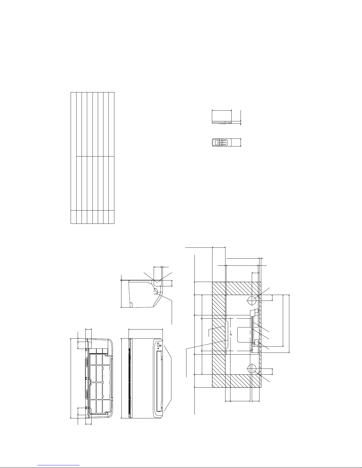
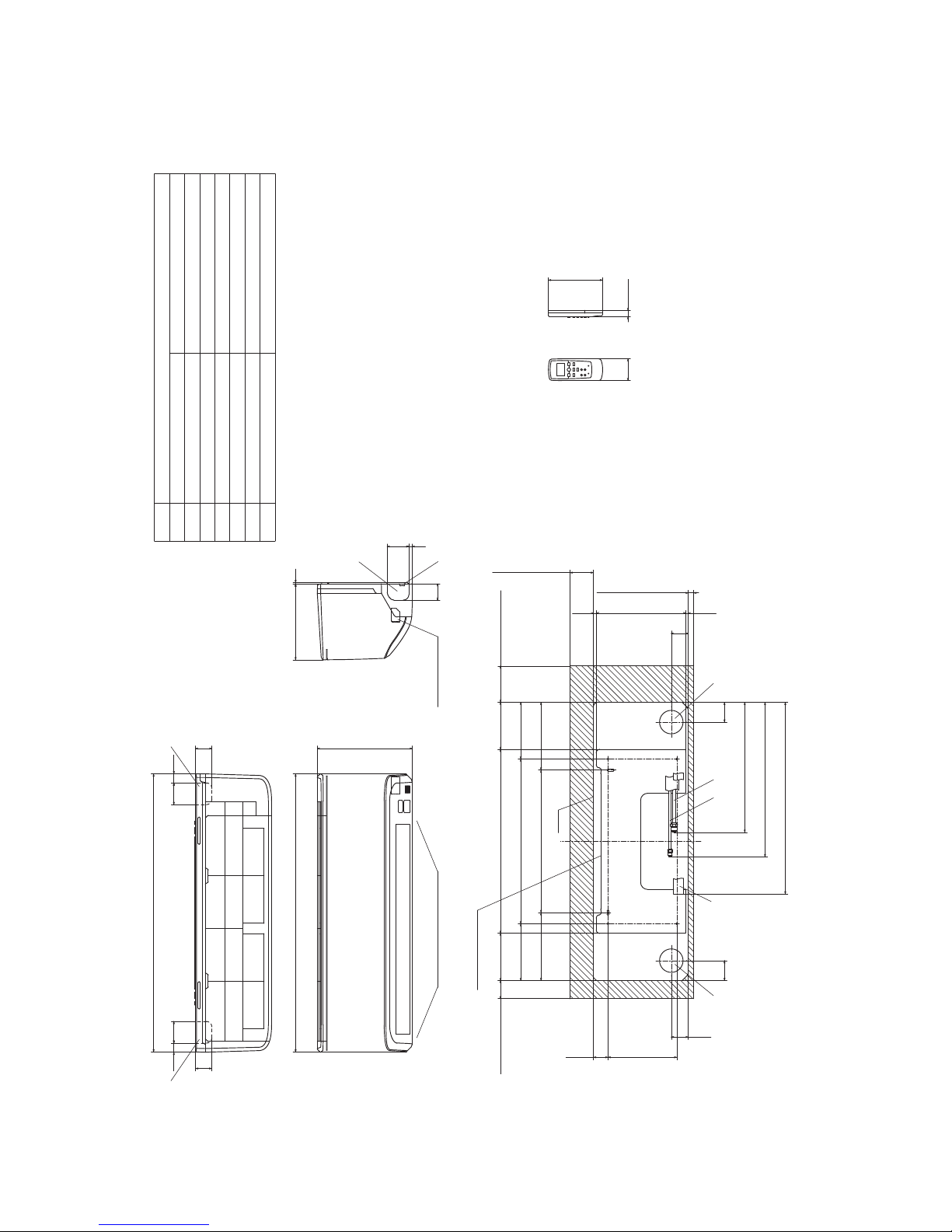
2. EXTERIOR DIMENSIONS
(1) Indoor units
Models SRK05CM, 05CM-3
SRK05CMP-3
SRK09CM-3, 09CM-4, 09CM-5
SRK09CMP-3, 09CMP-4
Note(1)Themodelnamelabelisattached
ontheundersideofthepanel.
60
150
17.3
2555
45
55
45
25
615
615
262
3210
45
609
44
56
247.1
(Servicespace)
15
7.2 7.7
44
56 40152.1
100
(Servicespace)
155.4
181.9 250 181.9
100
(Servicespace)
303 155.4
Unit
100
(Servicespace)
445.9
398.2
Installationplate
Unit:mm
Wirelessremotecontrol
Spaceforinstallationandservicewhenviewingfromthefront
Holeonwallforrightrearpiping
Holeonwallforleftrearpiping
Outletforwiring
Drainhose
Liquidpiping
F
ECD
B
Symbol
(φ65)
VP16
φ6.35(1/4")(Flare)
Content
(φ65)
Outletforpiping(onbothside)
G
Outletfordownpiping
(Refertotheaboveview)
D E AB C
Gaspiping
A
φ9.52(3/8")(Flare)
G
F
Terminalblock
-
16
-
'13•SRK-T-141
G
Terminal block
F
GG
Unit:mm
Wireless remote control
Outlet for down piping
(Refer to the above view)
Space for installation and service when viewing from the front
D E C
Hole on wall for right rear piping
Hole on wall for left rear piping
Gas piping
Outlet for wiring
Drain hose
Liquid piping
F
ECD
B
Symbol
A
(φ65)
VP16
φ6.35(1/4")(Flare)
Content
(φ65)
Outlet for piping(on both side)
G
φ12.7(1/2")(Flare)
AB
Note(1)The model name label is attached
on the underside of the indoor unit.
60
150
17.3
190 40.1
47
130.5 508 130.5
157 455 157
187.5 394 187.5
47
7.6247.5
6.9
(Service space)
65
(Service space)
15
50
(Service space)
100
(Service space)
55
409
449
530
55
Installation plate
Unit
6025 60 25
768.1
45
45
769
262
45
609
210 3
Models SRK12CM-3, 12CM-4, 12CM-5

-
17
-
'13•SRK-T-141
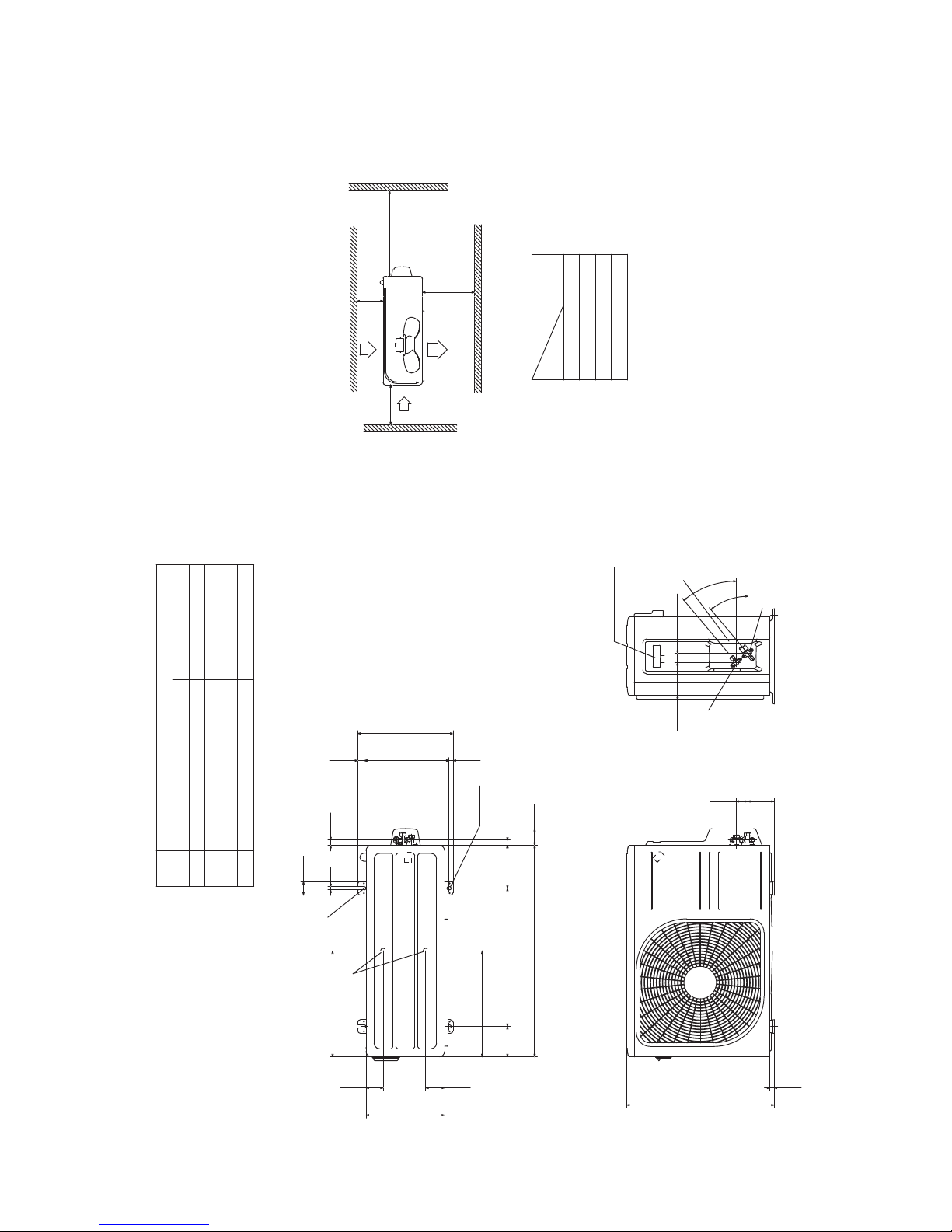
(2) Outdoor units
Models SRC05CM, 05CM-3
SRC05CMP-3
SRC09CM-3, 09CM-4, 09CM-5
SRC09CMP-3, 09CMP-4
)eralF()"8/3(25.9φ
Content
C Pipe/cable draw-out hole
D
E Anchor bolt hole
Drain discharge hole
Symbol
B
A Service valve connection(gas side)
M10×4places
φ20×2places
Service valve connection(liquid side)
)eralF()"4/1
(
53.6φ
Minimum installation space
Notes
.sedisruofllanosllawybdednuorrusebtontsumtI)1(
(2)The unit must be fixed with anchor bolts. An anchor bolt must not
protrude more than 15mm.
(3)Where the unit is subject to strong winds, lay it in such
a direction that the blower outlet faces perpendicular ly
to the dominant wind direction.
(4)Leave 1m or more space above the unit.
(5)A wall in front of the blower outlet must not exceed the unit height.
(6)The model name label is attached on the right side of the unit.
L2
L3
L4
L1 600
100
100
Examples of
Dimensions
Unit:mm
mm
installation
Outlet
Intake
L3
L1
L2
Intake
Service
space
( )
L4
Open
322
50
40
12
135
275
120.5
74.5 480 91 19.7
694.2
16.8304.414.8
336
2-16x12
Terminal block
147.2
2
0
°
2
0
°
86.3 43.2
16.5
437
E
D
BCA
-
18
-
'13•SRK-T-141
Models SRC12CM-3, 12CM-4, 12CM-5
)eralF()"4/1(53.6φ
Content
C Pipe/cable draw-out hole
D
E Anchor bolt hole
Drain discharge hole
Symbol
B
A Service valve connection(gas side)
M10×4places
φ20×2places
Service valve connection(liquid side)
)eralF()"2/1(7.21φ
L2
Intake
Outlet
Intake
L3
L1
Minimum installation space
Service
space
( )
Notes
.sedisruofllanosllawybdednuorrusebtontsumtI)1(
(2) The unit must be fixed with anchor bolts. An anchor bolt must not
protrude more than 15mm.
(3) Where the unit is subject to strong winds, lay it in such
a direction that the blower outlet faces perpendicularly
to the dominant wind direction.
(4) Leave 1m or more space above the unit.
(5) A wall in front of the blower outlet must not exceed the unit height.
(6) The model name label is attached on the right side of the unit.
L4
L2
L3
L4
L1
100
100
600
Open
Examples of
Dimensions
installation
15.8
543.8
390.6
390.6
63.469.4
290
111.6 510 158.4
780 61.9
18.9
14.8
351.6
2-16x12
312.5 24.3
50.6
12
97.7 42.5
Terminal block
40
°
4
0
°
138.4 33.5
19.9
D
E
A
C
B
Unit:mm
mm

-
19
-
'13•SRK-T-141
(3) Wireless remote control
Unit: mm
60
17.3
150
Models All model
Unit: mm
17.3
150
-
20
-
'13•SRK-T-141
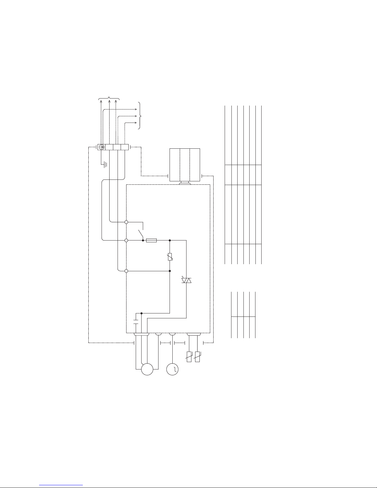
3. ELECTRICAL WIRING
(1) Indoor units
Models All model
Printed circuit board
Wireless
R-Amp
Display
CNE
WHRDBK
M
CNW
IC15
ZNR
153
CNU
CF
I
L 52C-3
52C
F
250V 3.15A
CONTROL BOX
Back up Sw
CNG
CNM
N
1〜
FM
I
T1
t°
t°
Th1
Th2
2/N
L
1
Symbol
Meaning of Marks
Parts name Symbol Parts name
Capacitor forCF
IFMI
FM
ZNR
FM
I
Fuse
Fan motor
Flap motor
Varistor
F
Th2
T1
Room temp. thermistor
Heat exchanger thermistor
Terminal block
Th1
BK
Color symbol
BL
Black
Blue
RD
WH
Red
White
BL
WH
BK
Power source
220/230/240V 50Hz
TO
OUTDOOR
UNIT
U
MFM
-
21
-
'13•SRK-T-141
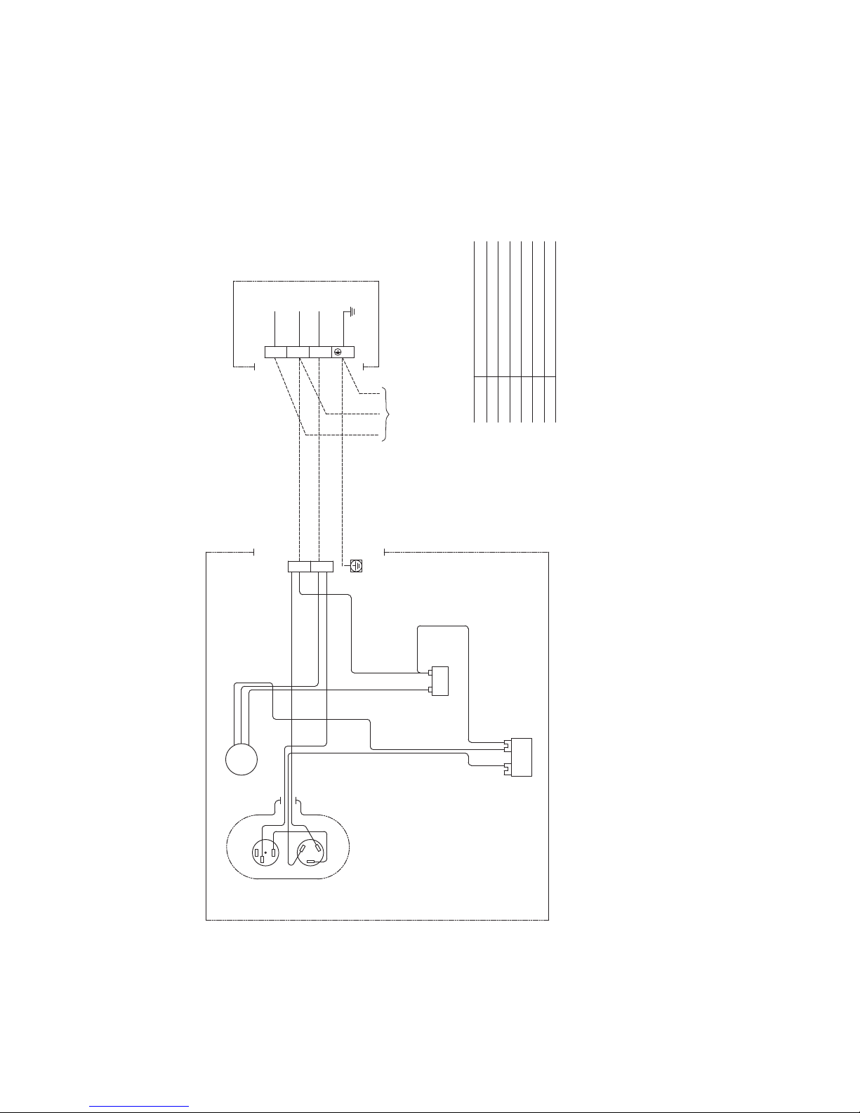
(2) Outdoor units
Models SRC05CM, 05CM-3
SRC05CMP-3
SRC09CM-3, 09CM-4, 09CM-5
SRC09CMP-3, 09CMP-4
Power source
220-240V 50Hz
INDOOR UNIT
FMo
BLACK
ORANGE
WHITE
RED
Cc
ORANGE
CFo
ORANGE
WHITE
WHITE
BLACK
BLACK
WHITE
1 2
T1
WHITE
CM
BLACK
BLACK
51C
2
3
1
RED
C
S
R
T2
WHITE
CAPACITOR
L
1
2/N
ORANGE
Symbol
Meaning of Marks
Parts name
Capacitor for CMCc
Capacitor for FMoCFo
Compressor motorCM
Fan motorFMo
Motor protector for CM51C
Terminal blockT1,T2
OUTDOOR UNIT
-
22
-
'13•SRK-T-141
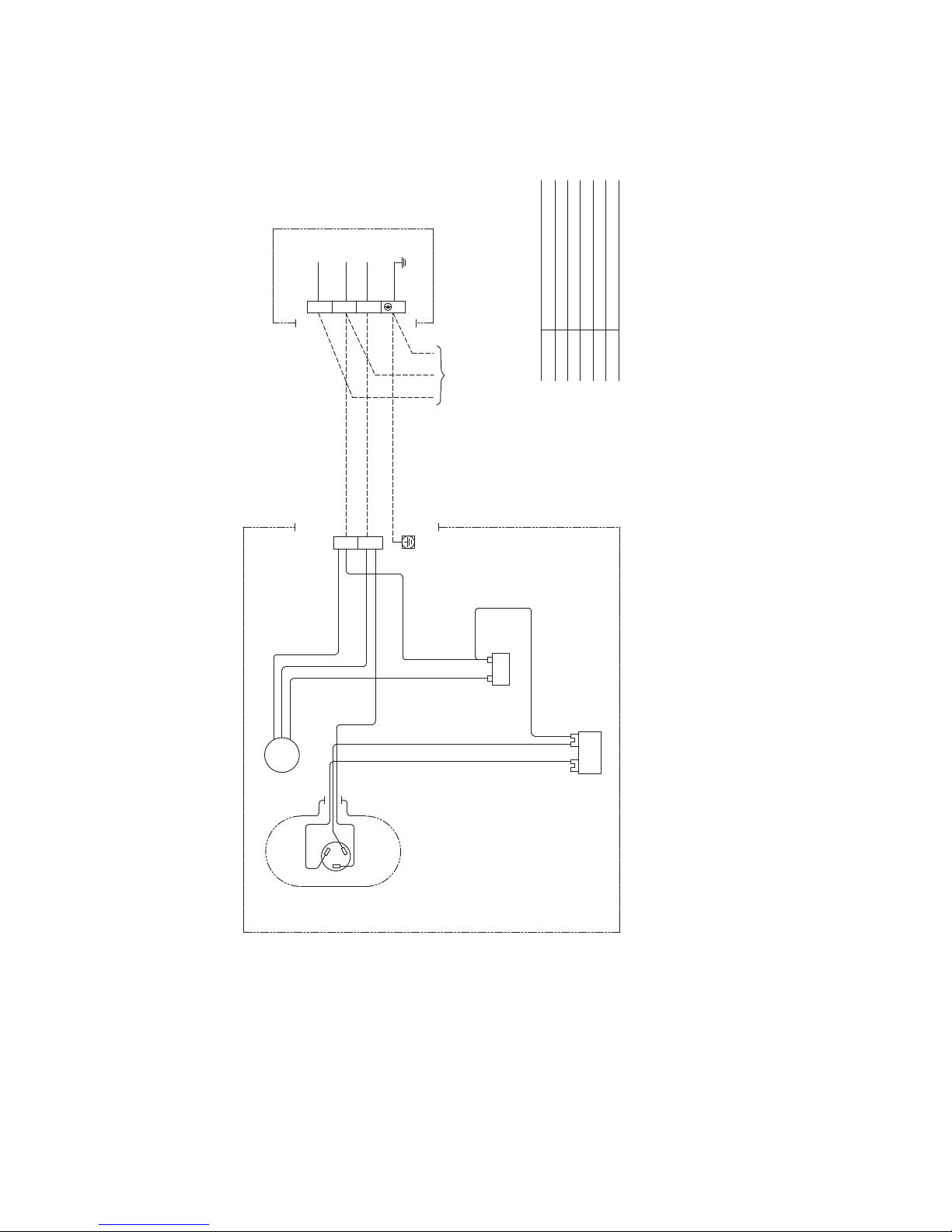
Models SRC12CM-3, 12CM-4, 12CM-5
Symbol
Meaning of Marks
Parts name
Capacitor for CMCc
Capacitor for FMoCFo
Compressor motorCM
Fan motorFMo
Terminal blockT1,T2
Powersource
220-240V50Hz
INDOORUNIT
BLACK
ORANGE
WHITE
RED
Cc
ORANGE
CFo
ORANGE
WHITE
WHITE
BLACK
BLACK
WHITE
1 2
T1
WHITE
CM
BLACK
RED
C
S
R
T2
WHITE
CAPACITOR
L
1
2/N
ORANGE
OUTDOORUNIT
BLACK
FMo
-
23
-
'13•SRK-T-141
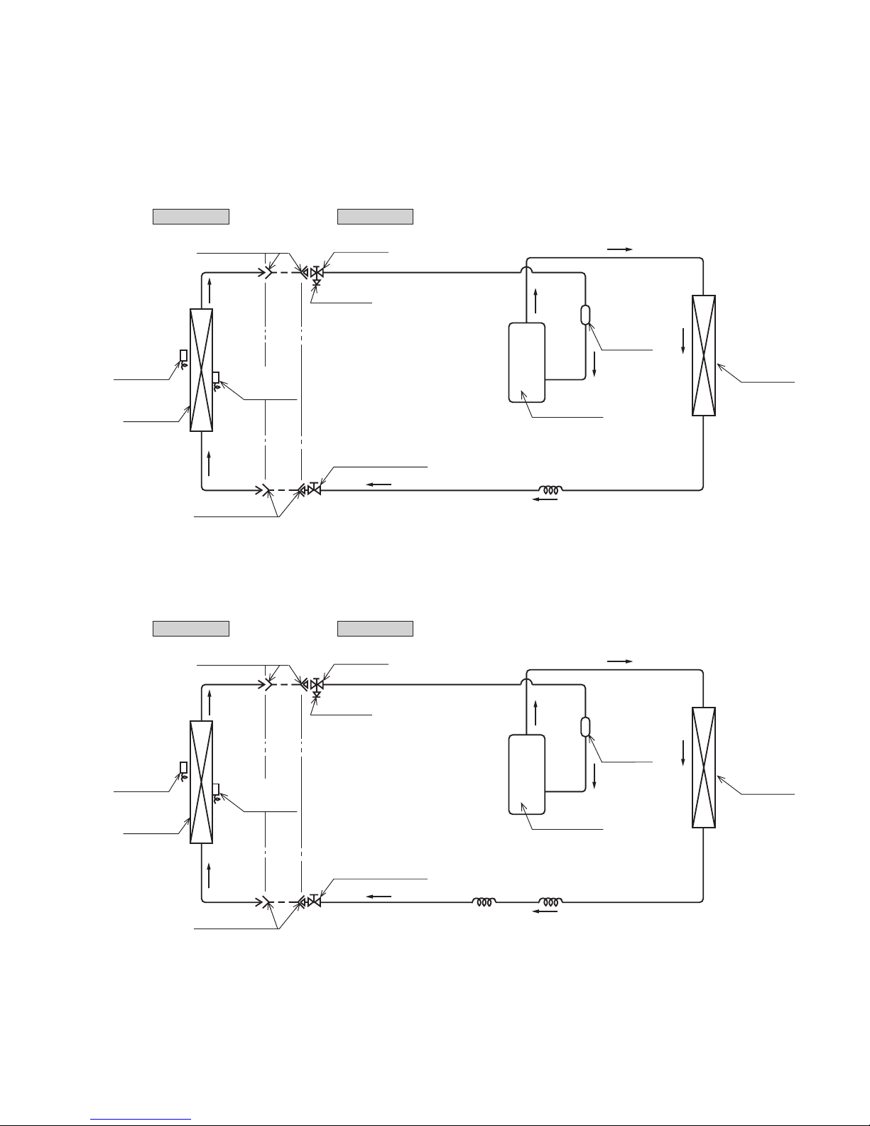
4. PIPING SYSTEM
Outdoor unitIndoor unit
Room temp.
sensor
Heat
exchanger
Flare connecting
Heat
exchanger
sensor
Piping
(Liquid)
ø6.35
Check joint
Service valve (Liquid)
Flare connecting
Heat
exchanger
Compressor
Accumulator
Service valve
(Gas)
Capillary tube
ø9.52
Piping
(Gas)
Outdoor unitIndoor unit
Room temp.
sensor
Heat
exchanger
Flare connecting
Heat
exchanger
sensor
Piping
(Liquid)
ø6.35
Check joint
Service valve (Liquid)
Flare connecting
Heat
exchanger
Compressor
Capillary tube
Accumulator
Service valve
(Gas)
Capillary tube
Piping
(Gas)
ø12.7
Models SRK05CM, 05CM-3
SRK05CMP-3
SRK09CM-3, 09CM-4, 09CM-5
SRK09CMP-3, 09CMP-4
Models SRK12CM-3, 12CM-4, 12CM-5

-
24
-
'13•SRK-T-141
5. RANGE OF USAGE & LIMITATIONS
Net capacity = Capacity shown on specification Correction factors as follows.
(1) Coefficient of cooling capacity in relation to temperatures
All model
Models
Item
Indoor return air temperature
(
Upper, lower limits
)
Outdoor air temperature
(
Upper, lower limits
)
Refer to the selection chart
Refrigerant line (one way) length
Max. 15m
Max. 5m (Outdoor unit is higher
)
Max. 5m (Outdoor unit is lower
)
Min. 3 minutes
Max. 10 times/h
Min. 85% of rating
Vertical height difference between
outdoor unit and indoor unit
Power source voltage
Voltage at starting
Frequency of ON−OFF cycle
ON and OFF interval
Rating 10%
14 16 18 20 22
15
20
25
30
35
40
0.6
0.7
0.8
0.9
1.0
1.1
1.2
1.3
43
24
ISO-T1 Standard ConditionIndoor air W.B. temperature °C W.B.
Cooling
Applicable range
Coefficient of cooling
capacity in relation
to temperature
Cooling operation
Outdoor air D.B.
temperature
°C D.B.
-
25
-
'13•SRK-T-141
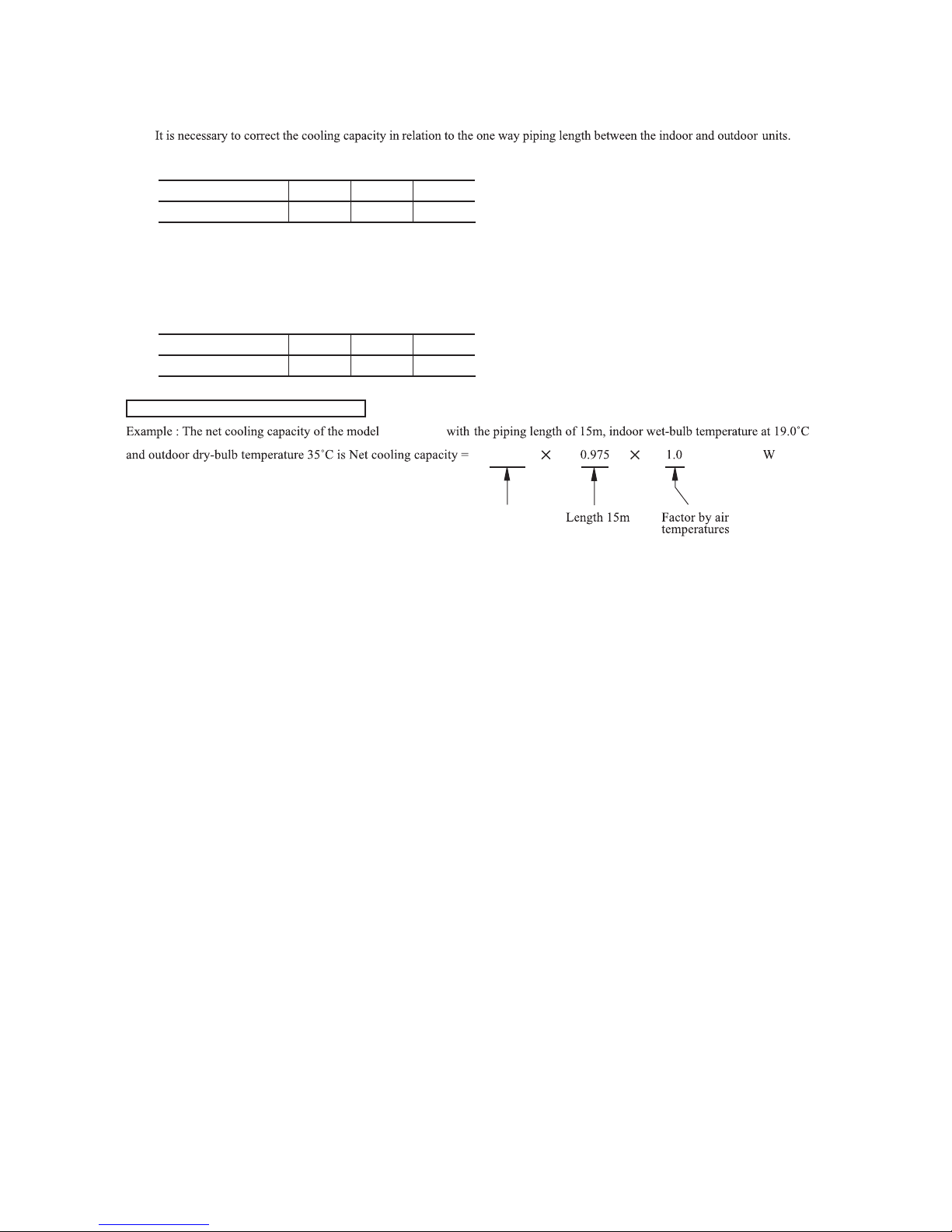
(2) Correction of cooling capacity in relation to one way length of refrigerant piping
How to obtain the cooling capacity
Model SRK05CM
=
Piping length [m]
Cooling
7.5
1.0
10
0.99 0.975
15
Models SRK05CM-3
SRK05CMP-3
SRK09CM-3, 09CM-4, 09CM-5
SRK09CMP-3, 09CMP-4
SRK12CM-3, 12CM-4, 12CM-5
Piping length [m]
Cooling
5
1.0
10
0.985 0.97
15
1500
SRK05CM
SRK05CM
1463
-
26
-
'13•SRK-T-141
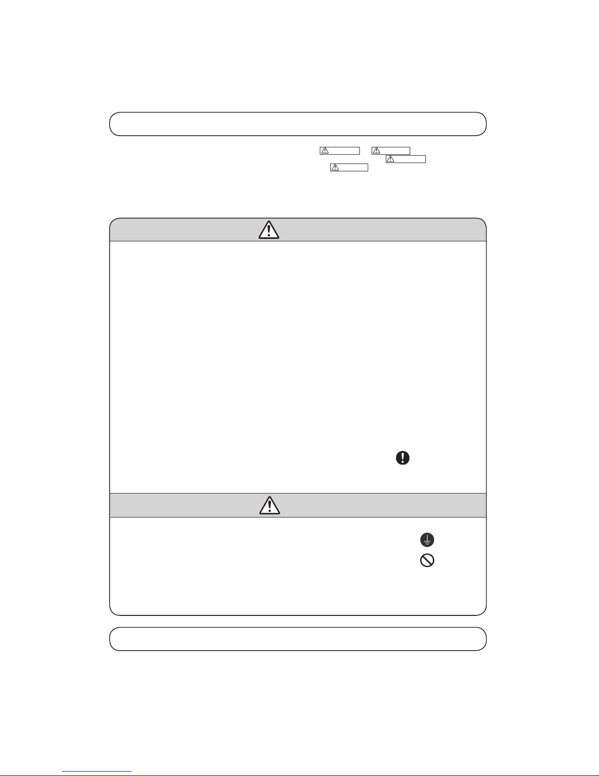
Safety precautions
• Please read these “Safety Precautions” first then accurately execute the installation work.
• Though the precautionary points indicated herein are divided under two headings,
WARNING
and
CAUTION
, those points which are related
to the strong possibility of an installation done in error resulting in death or serious injury are listed in the
WARNING
section. However, there
is also a possibility of serious consequences in relationship to the points listed in the
CAUTION
section as well. In either case, important safety
related information is indicated, so by all means, properly observe all that is mentioned.
• After completing the installation, along with confirming that no abnormalities were seen from the operation tests, please explain operating methods as
well as maintenance methods to the user (customer) of this equipment, based on the owner’s manual.
Moreover, ask the customer to keep this sheet together with the owner’s manual.
WARNING
• To disconnect the appliance from the mains supply this appliance must be connected to the mains by means of a circuit breaker or a switch (use a
recognized 10A) with a contact separation of at least 3mm.
• The appliance shall be installed in accordance with national wiring regulations.
• This systemshould be applied to placesas households, residences and thelike. Application to inferiorenvironment such as engineering shopcould
cause equipment malfunction.
• Please entrust installation to either the company which sold you the equipment or to a professional contractor. Defects from improper installations
can be the cause of water leakage, electric shocks and fires.
• Execute the installation accurately, based on following the installation manual. Again, improper installations can result in water leakage, electric
shocks and fires.
• For installation, confi rm that the installation site can suf ficiently support heavy weight. When strength is insuf fi
cient, injury can result from a
falling of the unit.
• For electrical work, please see that a licensed electrician executes the work while following the safety standards related to electrical equipment,
and local regulations as well as the installation instructions, and that only exclusive use circuits are used.
Insufficient power source circuit capacity and defective installment execution can be the cause of electric shocks and fires.
• This equipmentmust be installed with earth leakage circuit breaker (ELCB). Otherwise, it may causeelectrical shock and fire incase of equipment
breakdown.
• Accurately connect wiring using the proper cable, and insure that the external force of the cable is not conducted to the terminal connection part,
through properly securing it improper connection or securing can result in heat generation or fire.
• Take care that wiring does not rise upward, and accurately install the lid/service panel. It’s improper installation can also result heat generation or
fire.
• When setting up or moving the location of the air conditioner, do not mix air etc. or anything other than the designated refrigerant (R22) within
the refrigeration cycle.
Rupture and injury caused by abnormal high pressure can result from such mixing.
• Always use accessory parts and authorized parts for installation construction. Using parts not authorized by this company can result in water
leakage, electric shock, fire and refrigerant leakage.
• Ventilate the work area when refrigerant leaks during the operation.
Coming in contact with fire, refrigerant could generate toxic gas.
• Confirm after the foundation construction work that refrigerant does not leak.
If coming in contact with fire of a fan heater, a stove or movable cooking stove, etc., refrigerant leaking in the room could generate toxic gas.
CAUTION
• Execute proper grounding. Do not connect the ground wire to a gas pipe, water pipe, lightning rod or a telephone ground wire.
Improper placement of ground wires can result in electric shock.
• The installation of an earth leakage breaker is necessary depending on the established location of the unit.
No installing an earth leakage breaker may result in electric shock.
• Do not install the unit where there is a concern about leakage of combustible gas.
The rare even of leaked gas collecting around the unit could result in an outbreak of fire.
• For the drain pipe, follow the installation manual to insure that it allows proper drainage and thermally insulate it to prevent condensation.
Inadequate plumbing can result in water leakage and water damage to interior items.
• Install the outdoor unit so that the aluminum fins on the air heat exchanger cannot be touched. Failure to observe this may result in injury.
• Do not place objects near the outdoor unit or allow leaves to gather around the unit. If there are objects or leaves around the outdoor unit, small
animals may enter unit and contact electrical parts resulting in break down, emission of smoke or flame.
Cautions for installation
① The system should be applied to places as households, residences and the like.
② The equipment shall be installed in accordance with national wiring regulations.
③ The connection to the fixed wiring of the mains supply must be made via a double pole isolating switch with a contact gap of at least
3mm in each pole.
④ When the outdoor unit has a possibility of being overturned or being displaced and fall from its original installation position, the outdoor
unit should be fixed in its position by use of anchor bolts or wires.
6. APPLICATION DATA
Models SRK05CM, 05CM-3 SRK09CM-3, 09CM-4, 09CM-5
SRK05CMP-3 SRK09CMP-3, 09CMP-4
-
27
-
'13•SRK-T-141
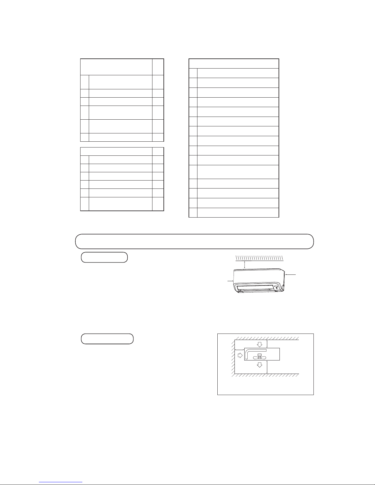
① A place where good air circulation can be obtained and where rain,
snow or sunshine will not directly strike the unit.
② A place where discharged hot air or unit’s operating sound will not be a
nuisance to the neighborhood.
③ A place where servicing space can be secured.
④ A place where vibration will not be enlarged.
*Avoid installing in the following places.
•A place near the bedroom and the like, so that the operation noise will
cause no trouble.
•A place where there is possibility of flammable gas leakage.
•A place exposed to strong wind.
•In a salt-laden atmosphere or a place where the generation of oil mist, vapor or fume is expected.
⑤ Blowing out port and suction port on the back side of the unit can be installed at a distance of 10cm from walls.
(In case the barrier is 1.2m or above in height, or is overhead, the sufficient space between the unit and wall shall be secured.)
⑥ When the unit is installed, the space of the following dimension and above shall be secured.
OUTDOOR UNIT
Selection of installation location
① Where there is no obstructions to the air flow and where the cooled
air can be evenly distributed.
② A solid place where the unit or the wall will not vibrate.
③ A place where there will be enough space for servicing. (Where
space mentioned right can be secured)
④ Where wiring and the piping work will be easy to conduct.
⑤ The place where receiving part is not exposed to the direct rays of
the sun or the strong rays of the street lighting.
⑥ A place where it can be easily drained.
⑦ A place separated at least 1m away from the television or the
radio.
(To prevent interfence to images and sounds.)
INDOOR UNIT
Standard accessories
(Installation kit)
Accessories for indoor unit
Q’ty
①
Installation board
(Attached to the rear of the indoor unit)
1
②
Wireless remote control 1
③
Remote control holder 1
④
Tapping screws
(for installation board 4dia. by 25mm)
5
⑤
Wood screw
(for remote control switch holder 3.5dia. by 16mm)
2
⑥
Battery [R03 (AAA, Micro) 1.5V]
2
Option parts Q’ty
ⓐ
Sealing plate 1
ⓑ
Sleeve 1
ⓒ
Inclination plate 1
ⓓ
Putty 1
ⓔ
Drain hose (extention hose) 1
ⓕ
Piping cover
(for insulation of connection piping)
1
Necessary tools for the installation work
1 Plus headed driver (Phillips screwdriver)
2 Knife
3 Saw
4 Tape measure
5 Hammer
6 Spanner wrench
7
Torque wrench
( )
14.0 ~ 61.0N · m
(1.4 ~ 6.1kgf · m)
8 Hole core drill (65mm in diameter)
9 Wrench key (Hexagon) [4m/m]
10 Vacuum pump
11
Vacuum pump adapter
(Anti-reverse flow type)
( )
Designed specifically
for R22
12
Gauge manifold
( )
Designed specifically
for R22
13
Charge hose
( )
Designed specifically
for R22
14
Flaring tool set
( )
Designed specifically
for R22
15
Gas leak detector
( )
Designed specifically
for R22
Note (1) If the wall is higher than 1.2 m or a ceiling is present,
distances larger thanindicated in the above table must
be provided.
Air intake
Air outlet
No obstacles
(Service space
for electrical
parts)
Air
intake
10 cm
MIN
60 cm MIN
10 cm MIN
Left
side
10 cm
10 cm
Right
side
10 cm
-
28
-
'13•SRK-T-141
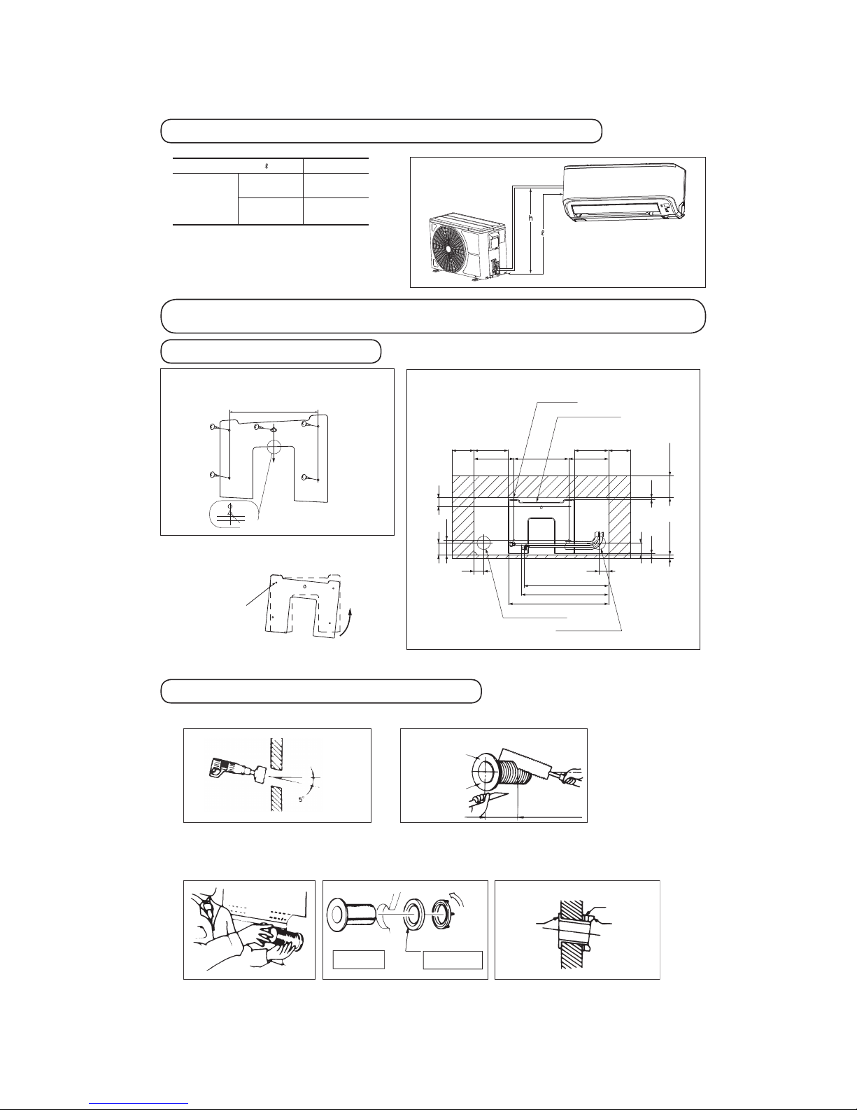
Installation of indoor unit
Installation of installation board
• Adjustment of the installation board inthe horizontal
direction is to be conducted with five screws in a
temporary tightened state.
• Adjust so that board will be level byturning the
board with the standard hole as the center.
Standard hole
Limitations for one way piping length and vertical height difference
One way piping length ( )
15 m
Vertical height
difference (h)
Outdoor
unit is lower
5 m
Outdoor
unit is higher
5 m
Look f or the inside wall structu res (Int ersediate support or
pillar and firaly install the uni t after l evel surface has be en
checked.)
Mating mark fo r level surface
250
* Leave extra space on the right side to enable removal of the lid screw.
INSTALLATION SPACE (INDOOR UNIT) (FRONT VIEW)
Unit : mm
Drilling of holes and fixture sleeve (Option parts)
Drill a hole with Ø65 whole core drill
Install the sleeve
Adjusting sleeve length
Note (1) Drill a hole with incline of 5 degree from
indoor side to outdoor side.
Wall thickness
+ 1.5 cm
Cut off the sleeve
collar that can be
seen from beneath
the unit.
Cut off the sleeve
collar in case of
drawing piping out
to rear.
Indoor side
Indoor side
Indoor side
View of sleeve when installed
Outdoor side
Outdoor side
Outdoor side
(Inserting sleeve) (*Sleeve + *Inclined + *Sealing plate)
Paste
Sleeve
Turn to
tighten
In cli ne d
flange
Seali ng
plate
Space for
service
Space for
service
Space for
service
Space for
service*
Indoor unit
181.9181.9
44
44
40
56
69.9
15
56
100
7.2 7.7
250
Installation board
Piping for Gas 398.2
Piping for Liquid 445.9
Drain hose 386.3 (
Ø16)
Piping hole (
Ø65)
Piping hole (Ø65)
100
100
155.4
155.4

-
29
-
'13•SRK-T-141
Preparation of indoor unit
① Mounting of connecting wires
ⓐ Remove the lid.
ⓑRemove the wiring clamp.
ⓒConnect the connecting wire securely to the terminal block.
Use cable for interconnection wiring to avoid loosening of the wires.
CENELEC code for cables Required field cables.
75CEI542ro)elpmaxE(5.1G4RNR50H
H Harmonized cable type
05 300/500 volts
R Natural-and/or synth. rubber wire insulation
N Polychloroprene rubber conductors insulation
R Standed core
srotcudnocforebmuN5ro4
G
One conductor of the cables is the earth conductor (yellow/green)
1.5 Section of copper wire (mm2)
• Connect the connection wire securely to the terminal block. If
the wire is not affixed completely, contact will be poor, and it
is dangerous as the terminal block may heat up and catch fire.
• Take care not to confuse the t erminal numbers for p ower
source indoor and outdoor connections.
•
Earthlead wireshall be longerthan theother lead wiresfor theelectrical
safety in case of the slipping out of the cord from the anchorage.
• The earth line of power cord must be properly earthed.
L
N
Connecting diagram.
Power supply
source
Terminal on the indoor unit
L 2/N
2
N
L
1
1
Terminal on the outdoor unit
• Affix the connection wire using the wiring clamp.
ⓓFix the connecting wire by wiring clamp.
ⓔAttach the lid.
② Shaping the pipe
③ Taping of the exterior
• Hold the bottom of the pipe and change its direction
before stretching it and shaping it.
• Tape only the portion that runs through the wall.
Always tape the crossover wires with the pipe.
④ Cautions when piping from the left and the rear center of the unit
[ Top View ]
• R emov e th e sc rew an d
pull th e drain hose, w hile
twisting.
• Re move i t wi th ha nd o r
pliers.
• I nser t th e d rai n c ap w hic h
was removed at procedure “2”
se cure ly us ing a hex ago nal
wrench etc.
Note: Be careful that if it is not
inserted securely, water leakage
may occur.
• Insert the drain hose securely,
pus h t he dr ain h ose wh ile
twisting. Install the screw.
Note: Be careful that if it is
not ins erted secure ly, water
leakage may occur.
Piping is possible in the rear,
left, left rear, l eft dow nward,
right or downward direction.
• Do not place the power supply cords above the gutter, because the
air conditioner is structuredin a way where condensation on theback
side is collected in to the drain pan before drainage.
• Do not make traps in the drain hose line.
Declining slope
Inverted slipe
Trap
* Leave space to allow
removal of this screw
after installation.
[ Drain hose changing procedures ]
Pipe
Drain hose
Terminal block
Screw*
Clamp
Lid
Left Side Piping Right Side Piping
Left rear piping
Left side piping
Right rear piping
Right side piping
Right
Left
Left rear
Rear
Downward
Left downward
1. Remove the drain hose. 2. Remove the drain cap. 3. Insert the drain cap. 4. Connect the drain hose.
Gutter
Pipes storage area
Wall
 Loading...