

Mitsubishi Heavy Industries SRK10CMV, SRK-13CMS-2, SRK13CMV, SRK19CMS, SRK25CMS Technical Manual
...
RESIDENTIAL AIR-CONDITIONING
TECHNICAL MANUAL & PARTS LIST
WALL MOUNTED TYPE
RESIDENTIAL AIR-CONDITIONER
(Split system, air cooled cooling only type)
SRK10CMV, 13CMV
SRK10CMS, 13CMS
SRK10CMS-2, 13CMS-2
SRK19CMS, 25CMS
Manual No.'12•SRK-T-137
-
1
-
'12•SRK-T-137
TECHNICAL MANUAL
1. SRK10CMV, 13CMV
SRK10CMS, 13CMS
SRK10CMS-2, 13CMS-2 ............................................. 2
2. SRK19CMS, 25CMS................................................... 38

-
2
-
'12•SRK-T-137
( )
1. SRK10CMV, 13CMV
SRK10CMS, 13CMS
SRK10CMS-2, 13CMS-2
WALL MOUNTED TYPE
RESIDENTIAL AIR-CONDITIONER
Split system, air cooled
cooling only type
'10 • SRK-T-099
CONTENTS
1.1 SPECIFICATIONS .................................................................................... 5
(2) Outdoor units .................................................................................... 10
(3) Wireless remote control
.................................................................... 11
........................................................................ 9
(1) Indoor units ......................................................................................... 9
1.2 EXTERIOR DIMENSIONS
1.3 ELECTRICAL WIRING ............................................................................. 12
(1) Indoor units ......................................................................................... 12
(2) Outdoor units ...................................................................................... 14
....................................................... 16
1.5 RANGE OF USAGE & LIMITATIONS
1.4 PIPING SYSTEM ..................................................................................... 15
............................................................................... 18
1.6 APPLICATION DATA
1.7 OUTLINE OF OPERATION CONTROL BY MICROCOMPUTER ........... 25
(6) 3D auto operation
............................................................................. 29
(7) Timer operation
................................................................................. 30
(5) Flap and louver control ..................................................................... 28
...................................................... 27(4) Custom cord switching procedure
........................................................................ 27(3) Auto restart function
(2) Unit ON/OFF button
.......................................................................... 27
(1) Operation control function by remote control
..................................... 25
(8) Installation location setting ................................................................. 30
(10) Outline of automatic operation .......................................................... 31
(9) Outline of cooling operation .............................................................. 31
(11) Protective control function
.................................................................. 32
.............................................................................. 33
.................... 34
(4) Troubleshooting procedure (If the air conditioner runs)
(3) Troubleshooting procedure
(If the air conditioner does not run at all)
....... 33
(1) Cautions
............................................................................................ 33
(2) Items to check before troubleshooting ................................................ 33
(5) Self-diagnosis table ............................................................................ 34
(6) Inspection procedures corresponding to detail of trouble ................... 35
1.8 MAINTENANCE DATA

-
3
-
'12•SRK-T-137
'10 • SRK-T-099
CONTENTS
1.1 SPECIFICATIONS .................................................................................... 5
(2) Outdoor units .................................................................................... 10
(3) Wireless remote control
.................................................................... 11
........................................................................ 9
(1) Indoor units ......................................................................................... 9
1.2 EXTERIOR DIMENSIONS
1.3 ELECTRICAL WIRING ............................................................................. 12
(1) Indoor units ......................................................................................... 12
(2) Outdoor units ...................................................................................... 14
....................................................... 16
1.5 RANGE OF USAGE & LIMITATIONS
1.4 PIPING SYSTEM ..................................................................................... 15
............................................................................... 18
1.6 APPLICATION DATA
1.7 OUTLINE OF OPERATION CONTROL BY MICROCOMPUTER ........... 25
(6) 3D auto operation
............................................................................. 29
(7) Timer operation
................................................................................. 30
(5) Flap and louver control ..................................................................... 28
...................................................... 27(4) Custom cord switching procedure
........................................................................ 27(3) Auto restart function
(2) Unit ON/OFF button
.......................................................................... 27
(1) Operation control function by remote control
..................................... 25
(8) Installation location setting ................................................................. 30
(10) Outline of automatic operation .......................................................... 31
(9) Outline of cooling operation .............................................................. 31
(11) Protective control function
.................................................................. 32
.............................................................................. 33
.................... 34
(4) Troubleshooting procedure (If the air conditioner runs)
(3) Troubleshooting procedure
(If the air conditioner does not run at all)
....... 33
(1) Cautions
............................................................................................ 33
(2) Items to check before troubleshooting ................................................ 33
(5) Self-diagnosis table ............................................................................ 34
(6) Inspection procedures corresponding to detail of trouble ................... 35
1.8 MAINTENANCE DATA

-
4
-
'12•SRK-T-137
'10 • SRK-T-099
(9) How to make sure of wireless remote control ..................................... 37
(7)
Phenomenon observed after shortcircuit, wire breakage on sensor
........ 36
(8) Checking the indoor electrical equipment
.......................................... 36
■How to read the model name
Example: SRK 10 C
Series code
Cooling only type
Product capacity
Model name SRK : Wall mounted type
SRC : Outdoor unit
MV

-
5
-
'12•SRK-T-137
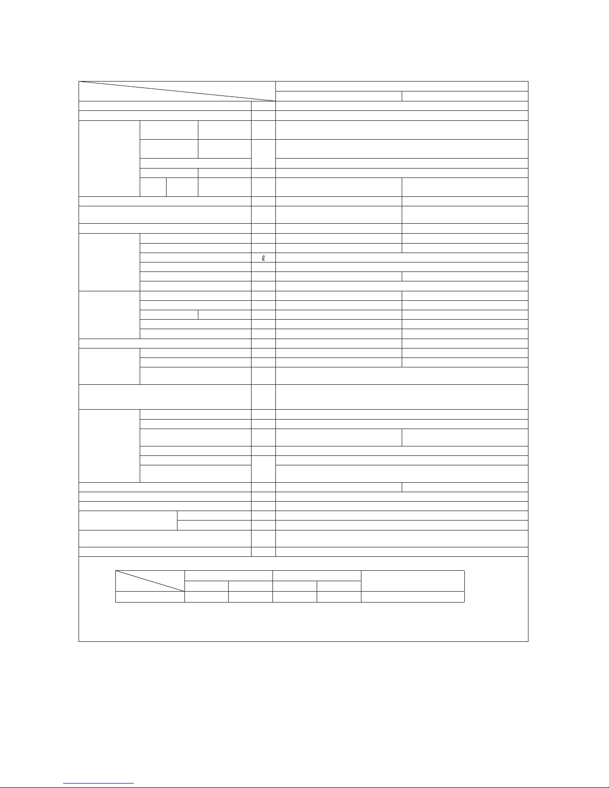
1.1 SPECIFICATIONS
Model
Item
SRK10CMV
Indoor unit SRK10CMV Outdoor unit SRC10CMV
Cooling capacity (1) W 2800
Power supply 1 Phase, 220 V, 50Hz
Operation
data (1)
Power
consumption
Cooling kW 0.77
Running
current
Cooling
A
3.5
Inrush current 18
COP Cooling 3.57
Noise
level
Cooling Sound level dB(A) 40 45
Exterior dimensions (Height x Width x Depth) mm 268 x 790 x 213 540 x 780 (+62) x 290
Exterior appearance
(Munsell color)
Fine snow
(8.0Y 9.3/0.1) near equivalent
Stucco white
(4.2Y 7.5/1.1) near equivalent
Net weight kg 8.5 28
Refrigerant
equipment
Compressor type & Q'ty — RMC201A011 (Rotary type) x 1
Motor (Starting method) kW — 0.69 (Line starting)
Refrigerant oil 0.35 (SUNISO 4GSI or ATMOS NM56)
Refrigerant (3) kg R22 0.58 (Pre-Charged up to the piping length of 7.5m)
Heat exchanger Louver fins & inner grooved tubing Louver fins & inner grooved tubing
Refrigerant control Capillary tubes
Air handling
equipment
Fan type & Q'ty Tangential fan x 1 Propeller fan x 1
Motor W 16 14.5
Air flow Cooling m3/min 10.0 26.5
Fresh air intake Not possible —
Air filter, Quality / Quantity Polypropylene net (washable) x 2 —
Shock & vibration absorber — Cushion rubber (for compressor)
Operation
control
Operation switch Wireless-Remote control —
Room temperature control Microcomputer thermostat —
Operation Display
RUN : Green, TIMER : Yellow, HI POWER : Green,
ECONO : Orange
Safety devices
Frost protection, Fan motor error protection,
Internal thermostat (for Compressor)
Installation
data
Refrigerant piping size (O.D) mm Liquid line: φ6.35 (1/4") Gas line: φ9.52 (3/8")
connecting method Flare connecting
Attached length of piping m
Liquid line : 0.4
Gas line : 0.33
—
Insulation for piping Necessary (Both sides), independent
Refrigerant line (one way) length
m
Max. 15
Vertical height difference between
outdoor unit and indoor unit
Max.5 (Outdoor unit is higher)
Max.5 (Outdoor unit is lower)
Drain hose Connectable (VP 16) —
Power cable 2.5m (3 Cores wih Earth)
Recommended breaker size A 20
Connection wiring
Size x Core number 1.5mm2 x 3 cores (Including earth cable)
Connecting method Terminal block (Screw fixing type)
Accessories (included)
Mounting kit
,
Clean filter (Natural enzyme filterx1, Photocatalytic washable deodorizing filterx1)
Option parts —
Note (1) The data are measured at the following conditions.
Item
Operation
Indoor air temperature Outdoor air temperature
Standards
DB WB DB WB
Cooling 27˚C 19˚C 35˚C 24˚C JIS C 9612, TISI 1155, 2134, 812
(2) This air-conditioner is manufactured and tested in conformity with the TISI.
(3) The operation data are applied to the 220V districts respectively.
(4) The refrigerant quantity to be charged includes the refrigerant in 7.5m connecting piping.
(Purging is not required even for the short piping.)
The pipe length is 7.5m.

-
6
-
'12•SRK-T-137
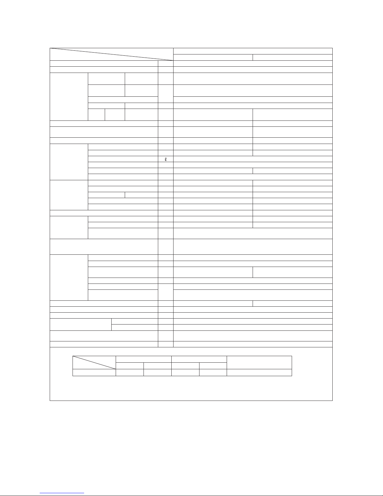
Model
Item
SRK13CMV
Indoor unit SRK13CMV Outdoor unit SRC13CMV
Cooling capacity (1) W 3600
Power supply 1 Phase, 220 V, 50Hz
Operation
data (1)
Power
consumption
Cooling kW 1.00
Running
current
Cooling
A
4.7
Inrush current 29
COP Cooling 3.60
Noise
level
Cooling Sound level dB(A) 40 49
Exterior dimensions (Height x Width x Depth) mm 268 x 790 x 213 540 x 780 (+62) x 290
Exterior appearance
(Munsell color)
Fine snow
(8.0Y 9.3/0.1) near equivalent
Stucco white
(4.2Y 7.5/1.1) near equivalent
Net weight kg 8.5 36
Refrigerant
equipment
Compressor type & Q'ty — RMC201A012 (Rotary type) x 1
Motor (Starting method) kW — 1.10(Line starting)
Refrigerant oil 0.45 (BARREL FREEZE 32SAM)
Refrigerant (3) kg R22 0.86 (Pre-Charged up to the piping length of 7.5m)
Heat exchanger Louver fins & inner grooved tubing Louver fins & inner grooved tubing
Refrigerant control Capillary tubes
Air handling
equipment
Fan type & Q'ty Tangential fan x 1 Propeller fan x 1
Motor W 16 25
Air flow Cooling m3/min 10.0 29.5
Fresh air intake Not possible —
Air filter, Quality / Quantity Polypropylene net (washable) x 2 —
Shock & vibration absorber — Cushion rubber (for compressor)
Operation
control
Operation switch Wireless-Remote control —
Room temperature control Microcomputer thermostat —
Operation Display
RUN : Green, TIMER : Yellow, HI POWER : Green,
ECONO : Orange
Safety devices
Frost protection, Fan motor error protection,
Internal thermostat (for Compressor)
Installation
data
Refrigerant piping size (O.D) mm Liquid line :φ6.35 (1/4") Gas line :φ12.7 (1/2")
connecting method Flare connecting
Attached length of piping m
Liquid line : 0.40
Gas line : 0.33
—
Insulation for piping Necessary (Both sides), independent
Refrigerant line (one way) length
m
Max. 15
Vertical height difference between
outdoor unit and indoor unit
Max.5 (Outdoor unit is higher)
Max.5 (Outdoor unit is lower)
Drain hose Connectable (VP 16) —
Power cable 2.5m (3 Cores wih Earth)
Recommended breaker size A 20
Connection wiring
Size x Core number 1.5mm2 x 3 cores (Including earth cable)
Connecting method Terminal block (Screw fixing type)
Accessories (included)
Mounting kit
,
Clean filter (Natural enzyme filterx1, Photocatalytic washable deodorizing filterx1)
Option parts —
Note (1) The data are measured at the following conditions.
Item
Operation
Indoor air temperature Outdoor air temperature
Standards
DB WB DB WB
Cooling 27˚C 19˚C 35˚C 24˚C JIS C 9612, TISI 1155, 2134, 812
(2) This air-conditioner is manufactured and tested in conformity with the TISI.
(3) The operation data are applied to the 220V districts respectively.
(4) The refrigerant quantity to be charged includes the refrigerant in 7.5m connecting piping.
(Purging is not required even for the short piping.)
The pipe length is 7.5m.
-
7
-
'12•SRK-T-137
Model
Item
SRK10CMS(-2)
Indoor unit SRK10CMS(-2) Outdoor unit SRC13CMS(-2)
Cooling capacity (1) W 2800
Power supply 1 Phase, 220 V, 50Hz
Operation
data (1)
Power
consumption
Cooling kW 0.77
Running
current
Cooling
A
3.5
Inrush current 18
COP Cooling 3.57
Noise
level
Cooling Sound level dB(A) 40 45
Exterior dimensions (Height x Width x Depth) mm 268 x 790 x 213 540 x 780 (+62) x 290
Exterior appearance
(Munsell color)
Fine snow
(8.0Y 9.3/0.1) near equivalent
Stucco white
(4.2Y 7.5/1.1) near equivalent
Net weight kg 8.5 28
Refrigerant
equipment
Compressor type & Q'ty — RMC201A011 (Rotary type) x 1
Motor (Starting method) kW — 0.69 (Line starting)
Refrigerant oil 0.35 (SUNISO 4GSI or ATMOS NM56)
Refrigerant (3) kg R22 0.58 (Pre-Charged up to the piping length of 7.5m)
Heat exchanger Louver fins & inner grooved tubing Louver fins & inner grooved tubing
Refrigerant control Capillary tubes
Air handling
equipment
Fan type & Q'ty Tangential fan x 1 Propeller fan x 1
Motor W 16 15
Air flow Cooling m3/min 10.0 26.5
Fresh air intake Not possible —
Air filter, Quality / Quantity Polypropylene net (washable) x 2 —
Shock & vibration absorber — Cushion rubber (for compressor)
Operation
control
Operation switch Wireless-Remote control —
Room temperature control Microcomputer thermostat —
Operation Display
RUN : Green, TIMER : Yellow, HI POWER : Green,
3D AUTO : Green
Safety devices
Frost protection, Fan motor error protection,
Internal thermostat (for Compressor)
Installation
data
Refrigerant piping size (O.D) mm Liquid line: φ6.35 (1/4") Gas line: φ9.52 (3/8")
connecting method Flare connecting
Attached length of piping m
Liquid line : 0.4
Gas line : 0.33
—
Insulation for piping Necessary (Both sides), independent
Refrigerant line (one way) length
m
Max. 15
Vertical height difference between
outdoor unit and indoor unit
Max.5 (Outdoor unit is higher)
Max.5 (Outdoor unit is lower)
Drain hose Connectable (VP 16) —
Power cable 2.5m (3 Cores wih Earth)
Recommended breaker size A 20
Connection wiring
Size x Core number 1.5mm2 x 3 cores (Including earth cable)
Connecting method Terminal block (Screw fixing type)
Accessories (included)
Mounting kit
,
Clean filter (Natural enzyme filterx1, Photocatalytic washable deodorizing filterx1)
Option parts —
Note (1) The data are measured at the following conditions.
Item
Operation
Indoor air temperature Outdoor air temperature
Standards
DB WB DB WB
Cooling 27˚C 19˚C 35˚C 24˚C JIS C 9612, TISI 1155, 2134, 812
(2) This air-conditioner is manufactured and tested in conformity with the TISI.
(3) The operation data are applied to the 220V districts respectively.
(4) The refrigerant quantity to be charged includes the refrigerant in 7.5m connecting piping.
(Purging is not required even for the short piping.)
The pipe length is 7.5m.
-
8
-
'12•SRK-T-137
Model
Item
SRK13CMS(-2)
Indoor unit SRK13CMS(-2) Outdoor unit SRC13CMS(-2)
Cooling capacity (1) W 3600
Power supply 1 Phase, 220 V, 50Hz
Operation
data (1)
Power
consumption
Cooling kW 1.00
Running
current
Cooling
A
4.7
Inrush current 29
COP Cooling 3.60
Noise
level
Cooling Sound level dB(A) 40 49
Exterior dimensions (Height x Width x Depth) mm 268 x 790 x 213 540 x 780 (+62) x 290
Exterior appearance
(Munsell color)
Fine snow
(8.0Y 9.3/0.1) near equivalent
Stucco white
(4.2Y 7.5/1.1) near equivalent
Net weight kg 8.5 36
Refrigerant
equipment
Compressor type & Q'ty — RMC201A012 (Rotary type) x 1
Motor (Starting method) kW — 1.10(Line starting)
Refrigerant oil 0.45 (BARREL FREEZE 32SAM)
Refrigerant (3) kg R22 0.86 (Pre-Charged up to the piping length of 7.5m)
Heat exchanger Louver fins & inner grooved tubing Louver fins & inner grooved tubing
Refrigerant control Capillary tubes
Air handling
equipment
Fan type & Q'ty Tangential fan x 1 Propeller fan x 1
Motor W 16 25
Air flow Cooling m3/min 10.0 29.5
Fresh air intake Not possible —
Air filter, Quality / Quantity Polypropylene net (washable) x 2 —
Shock & vibration absorber — Cushion rubber (for compressor)
Operation
control
Operation switch Wireless-Remote control —
Room temperature control Microcomputer thermostat —
Operation Display
RUN : Green, TIMER : Yellow, HI POWER : Green,
3D AUTO : Green
Safety devices
Frost protection, Fan motor error protection,
Internal thermostat (for Compressor)
Installation
data
Refrigerant piping size (O.D) mm Liquid line :φ6.35 (1/4") Gas line :φ12.7 (1/2")
connecting method Flare connecting
Attached length of piping m
Liquid line : 0.40
Gas line : 0.33
—
Insulation for piping Necessary (Both sides), independent
Refrigerant line (one way) length
m
Max. 15
Vertical height difference between
outdoor unit and indoor unit
Max.5 (Outdoor unit is higher)
Max.5 (Outdoor unit is lower)
Drain hose Connectable (VP 16) —
Power cable 2.5m (3 Cores wih Earth)
Recommended breaker size A 20
Connection wiring
Size x Core number 1.5mm2 x 3 cores (Including earth cable)
Connecting method Terminal block (Screw fixing type)
Accessories (included)
Mounting kit
,
Clean filter (Natural enzyme filterx1, Photocatalytic washable deodorizing filterx1)
Option parts —
Note (1) The data are measured at the following conditions.
Item
Operation
Indoor air temperature Outdoor air temperature
Standards
DB WB DB WB
Cooling 27˚C 19˚C 35˚C 24˚C JIS C 9612, TISI 1155, 2134, 812
(2) This air-conditioner is manufactured and tested in conformity with the TISI.
(3) The operation data are applied to the 220V districts respectively.
(4) The refrigerant quantity to be charged includes the refrigerant in 7.5m connecting piping.
(Purging is not required even for the short piping.)
The pipe length is 7.5m.
-
9
-
'12•SRK-T-137
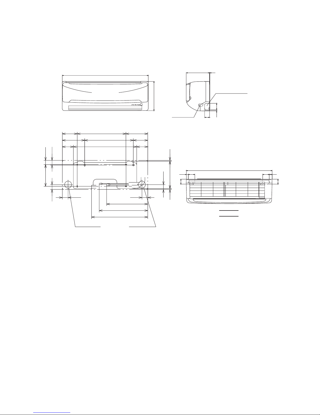
1.2 EXTERIOR DIMENSIONS
(1) Indoor units
Models All model
Piping hole (ø65)
( )
Piping hole (ø65)
53.5
380.6
Piping for Liquid 448.6 (ø6.35)
10 :ø9.52
13 :ø12.7
Piping for Gas
Drain hose 520 (ø16)
53.5
44.5
252.2
7.5
8.3
102.5
585
102.5
133.5450206.5
202450138
44.5
43.2
39.3
200
45
45
60
17.5
60
27
788
Terminal block
Piping hole right (left)
9
213 3
45
60
268
790
→
A
VIEW A
Unit:mm
-
10
-
'12•SRK-T-137
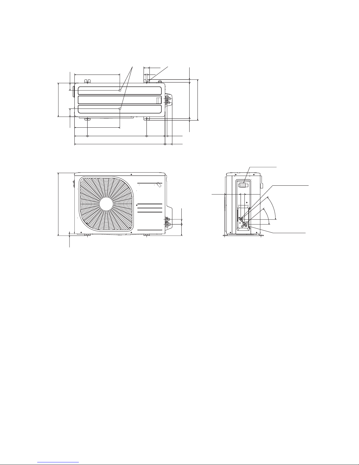
(2) Outdoor units
Models All model
63.4
390.6
390.6
69.4
111.6 510 158.4
780 61.9
17.9
14.8 312.5 24.3
351.6
50.6
12
290
15.8
540
97.7 42.5
40°
40°
138.4 33.5
Anchor bolt holeDrain discharge holes
Terminal block
Service valve (Liquid)
Flare connection
ø6.35(1/4")
Service valve (Gas)
Flare connection
10: ø9.52(3/8")
13: ø12.7(1/2")
Unit:mm

-
11
-
'12•SRK-T-137
(3) Wireless remote control
Unit: mm
60
17.3
150
Unit: mm
60
17.3
150
Models SRK10CMS, 13CMS
SRK10CMS-2, 13CMS-2
Models SRK10CMV, 13CMV
Unit: mm
17.3
150
Unit: mm
17.3
150

-
12
-
'12•SRK-T-137
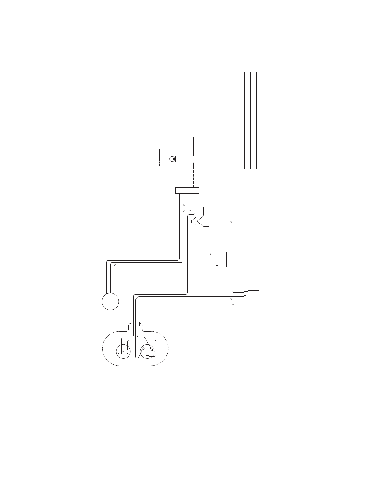
1.3 ELECTRICAL WIRING
U
MFM
BK
Color symbol
BL
BR
LB
YE
RD
YG
WH
Red
Yellow/Green
White
Black
Blue
Brown
Light blue
Yellow
Symbol
Meaning of Marks
Parts name Symbol Parts name
Capacitor forCF
I
FMIFM
ZNR
FM
I
Fuse
Fan motor
Flap motor
Varistor
Th2
T
Room temp. thermistor
Heat exchanger thermistor
Terminal block
F
Th1
Power source
220/230/240V 50Hz
YG
LB
BR
Printed circuit board
T
YG
BL
BR
WH
BK
TO
OUTDOOR
UNIT
Th1
Th2
Wireless
R-Amp
Display
CNE
CNG
YEWHRD
M
CNW
IC15
ZNR
153
CNU
CF
I
52C-4 52C-3
52C
F
250V 3.15A
CONTROL BOX
1
2
Back up Sw
CNM
N
t°
1~
FM
I
t°
(1) Indoor units
Models SRK10CMV, 13CMV
-
13
-
'12•SRK-T-137
Models SRK10CMS, 13CMS
SRK10CMS-2, 13CMS-2
U
M
M
M
LM
LM
FM
BK
Color symbol
BL
BR
LB
YE
RD
YG
WH
Red
Yellow/Green
White
Black
Blue
Brown
Light blue
Yellow
Symbol
Meaning of Marks
Parts name Symbol Parts name
Capacitor forCF
I
FMIFM
ZNR
FM
I
Fuse
Fan motor
Flap motor
Varistor
Louver motor(RIGHT)LM
Th2
T
Room temp. thermistor
Heat exchanger thermistor
Terminal block
F Th1
Power source
220/230/240V 50Hz
YG
LB
BR
Printed circuit board
T
YG
BL
BR
WH
BK
TO
OUTDOOR
UNIT
Th1
Th2
Wireless
R-Amp
Display
CNE
CNG
YEWHRD
M
CNW
CNY
IC15
ZNR
153
CNU
CF
I
52C-4 52C-3
52C
F
250V 3.15A
CONTROL BOX
1
2
Back up Sw
CNX
CNM
N
R
Louver motor(LEFT)LM
L
t°
1~
R
L
FM
I
t°
-
14
-
'12•SRK-T-137
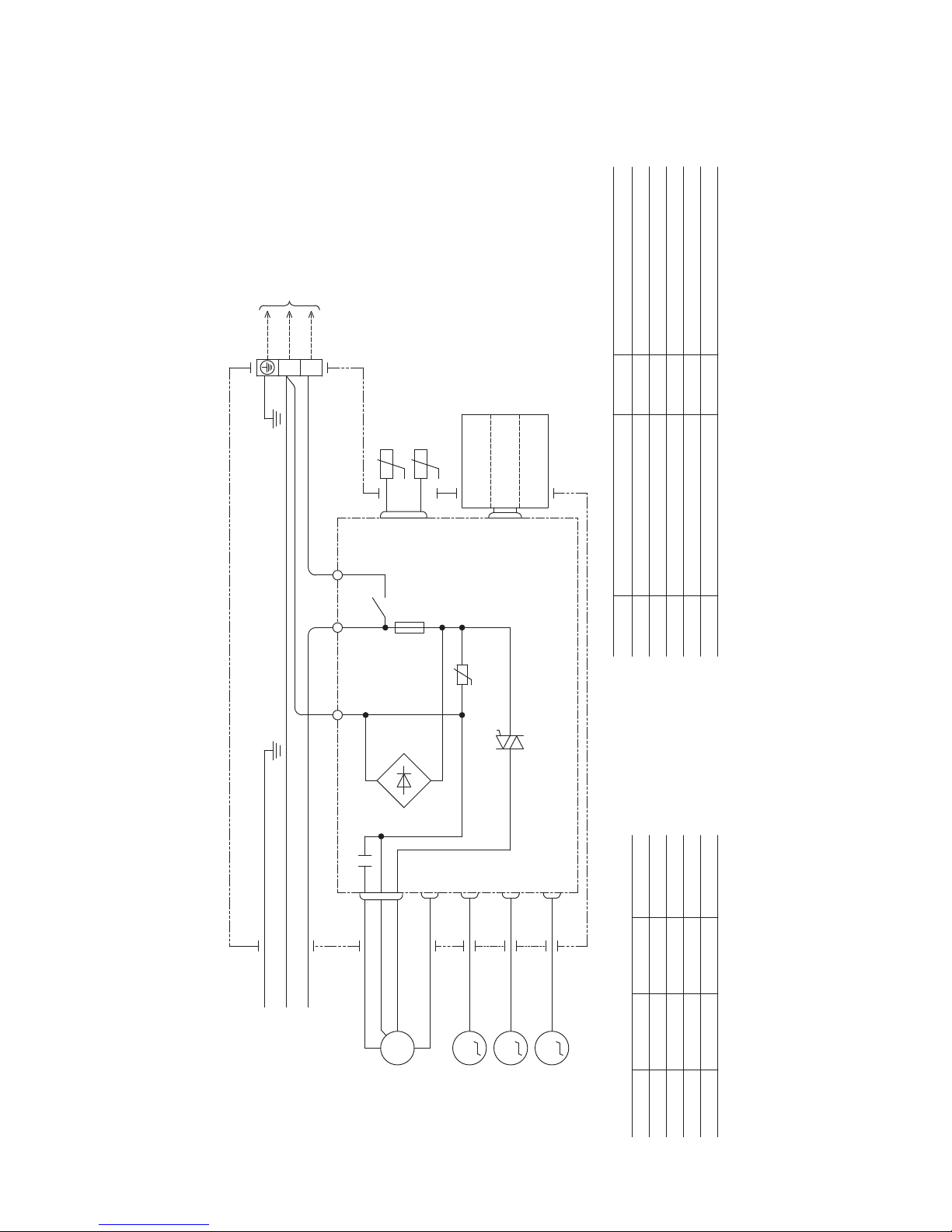
(2) Outdoor units
Models All model
Symbol
Meaning of Marks
Parts name
Capacitor for CMCc
Capacitor for FMoCFo
Compressor motorCM
Fan motorFMo
Motor protector for CM51C
Terminal blockT
ConnectorSh
1
Power source
220-240V 50Hz
INDOOR
UNIT
FMo
BLACK
ORANGE
WHITE
RED
WHITE
Cc
ORANGE
CFo
WHITE
ORANGE
WHITE
WHITE
BLACK
BLACK
WHITE
1 2
T
WHITE
CM
BLACK
BLACK
51C
2
3
1
RED
C
S
R
Sh
1
T
WHITE
1 2
CAPACITOR
-
15
-
'12•SRK-T-137
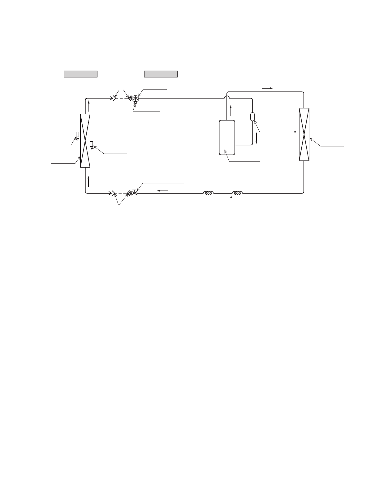
1.4 PIPING SYSTEM
Outdoor unitIndoor unit
Room temp.
sensor
Heat
exchanger
Flare connecting
Heat
exchanger
sensor
Piping
(Liquid)
ø6.35
Check joint
Service valve (Liquid)
Flare connecting
Heat
exchanger
Compressor
Capillary tube
Accumulator
Service valve
(Gas)
Capillary tube
10 : ø9.52
Piping
(Gas)
13 : ø12.7
( )
Models All model
-
16
-
'12•SRK-T-137
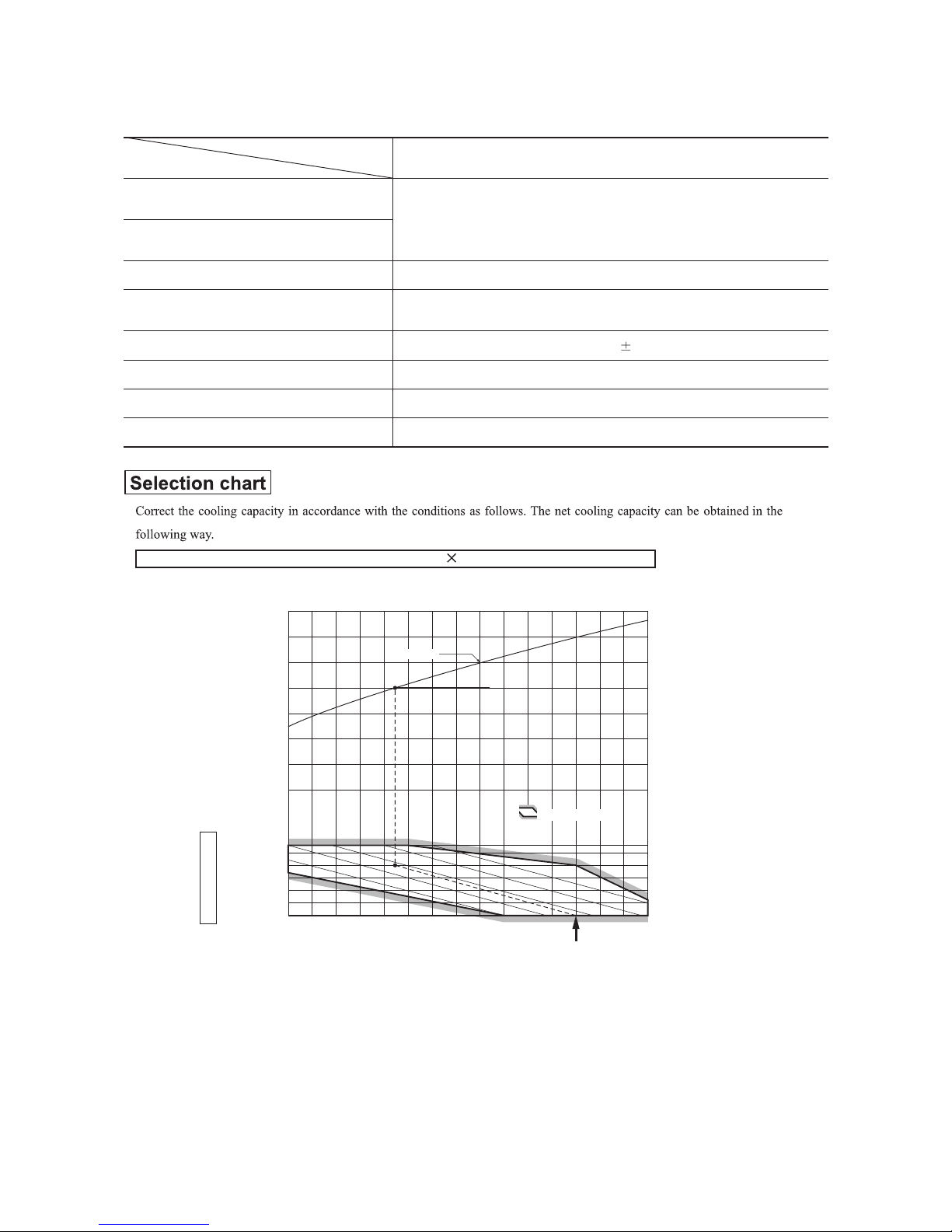
1.5 RANGE OF USAGE & LIMITATIONS
Net capacity = Capacity shown on specification Correction factors as follows.
(1) Coefficient of cooling capacity in relation to temperatures
All model
Models
Item
Indoor return air temperature
(
Upper, lower limits
)
Outdoor air temperature
(
Upper, lower limits
)
Refer to the selection chart
Refrigerant line (one way) length
Max. 15m
Max. 5m (Outdoor unit is higher
)
Max. 5m (Outdoor unit is lower
)
Min. 3 minutes
Max. 10 times/h
Min. 85% of rating
Vertical height difference between
outdoor unit and indoor unit
Power source voltage
Voltage at starting
Frequency of ON−OFF cycle
ON and OFF interval
Rating 10%
14 16 18 20 22
15
20
25
30
35
40
0.6
0.7
0.8
0.9
1.0
1.1
1.2
1.3
43
24
ISO-T1 Standard ConditionIndoor air W.B. temperature °C W.B.
Cooling
Applicable range
Coefficient of cooling
capacity in relation
to temperature
Cooling operation
Outdoor air D.B.
temperature
°C D.B.
-
17
-
'12•SRK-T-137
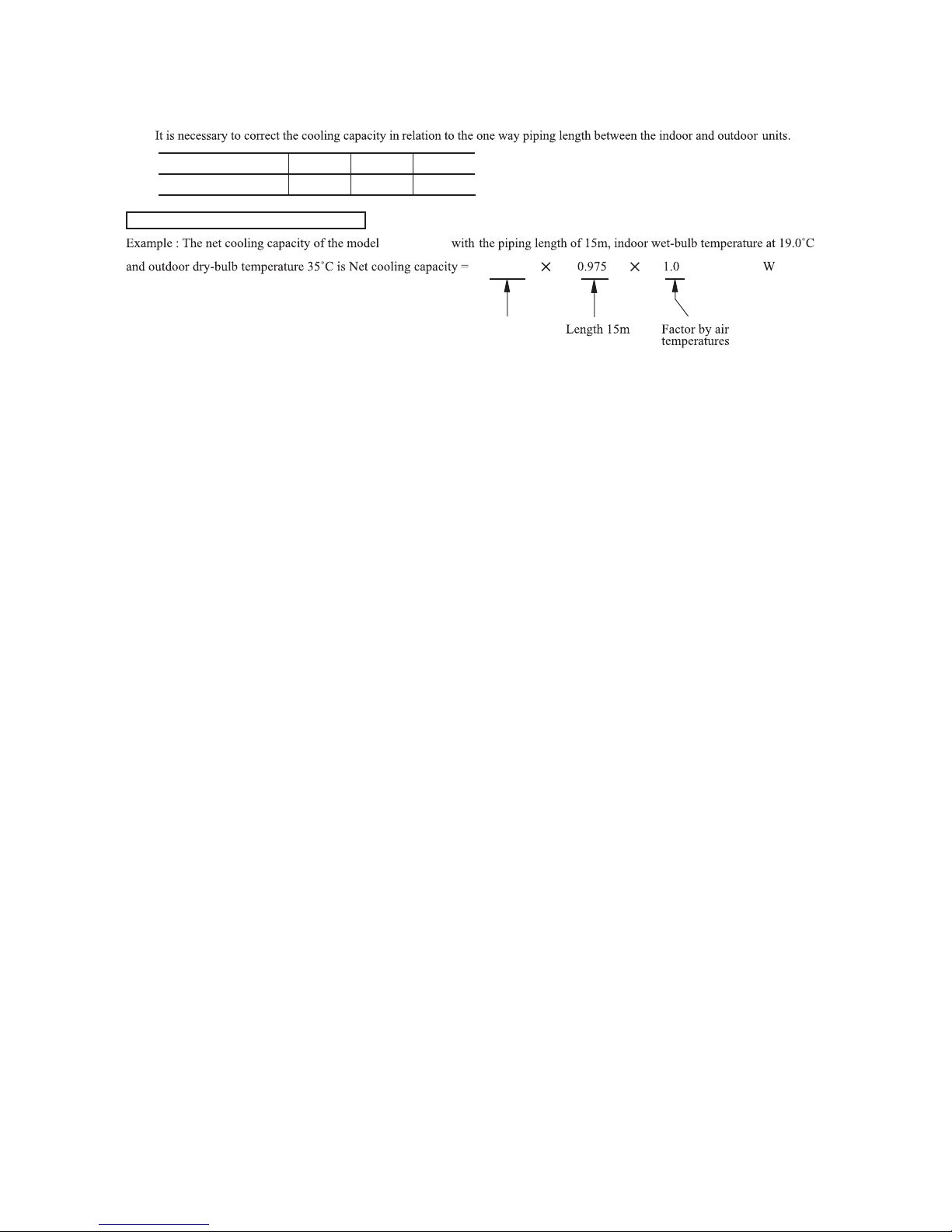
(2) Correction of cooling capacity in relation to one way length of refrigerant piping
How to obtain the cooling capacity
=
Piping length [m]
Cooling
7
1.0
10
0.99 0.975
15
3600
SRK13CMV
SRK13CMV
3510
-
18
-
'12•SRK-T-137
1.6 APPLICATION DATA
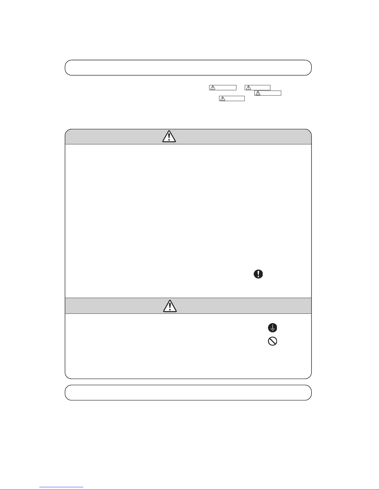
Safety precautions
• Please read these “Safety Precautions” first then accurately execute the installation work.
• Though the precautionary points indicated herein are divided under two headings, WARNING and CAUTION , those points which are
related to the strong possibility of an installation done in error resulting in death or serious injury are listed in the WARNING section. However,
there is also a possibility of serious consequences in relationship to the points listed in the CAUTION section as well. In either case, important
safety related information is indicated, so by all means, properly observe all that is mentioned.
• After completing the installation, along with confirming that no abnormalities were seen from the operation tests, please expla in operating methods
as well as maintenance methods to the user (customer) of this equipment, based on the owner’s manual.
Moreover, ask the customer to keep this sheet together with the owner’s manual.
WARNING
• To disconnect the appliance from the mains supply this appliance must be connected to the mains by means of a circuit breaker or a switch (use
a recognized 20A) with a contact separation of at least 3mm.
• The appliance shall be installed in accordance with national wiring regulations.
• This system should be applied to places as households, residences and the like. Application to inferior environment such as engineering shop
could cause equipment malfunction.
• Please entrust installation to either the company which sold you the equipment or to a professional contractor. Defects from improper installations can be the cause of water leakage, electric shocks and fires.
• Execute the installation accurately, based on following the installation manual. Again, improper installations can result in water leakage,
electric shocks and fires.
• For installation, confirm that the installation site can sufficiently support heavy weight. When strength is insufficient, injury can result from a
falling of the unit.
• For electrical work, please see that a licensed electrician executes the work while following the safety standards related to electrical equipment,
and local regulations as well as the installation instructions, and that only exclusive use circuits are used.
Insufficient power source circuit capacity and defective installment execution can be the cause of electric shocks and fires.
• Accurately connect wiring using the proper cable, and insure that the external force of the cable is not conducted to the terminal connection
part, through properly securing it improper connection or securing can result in heat generation or fire.
• Take care that wiring does not rise upward, and accurately install the lid/service panel. It’s improper installation can also result heat generation
or fire.
• When setting up or moving the location of the air conditioner, do not mix air etc. or anything other than the designated refrigerant (R22) within
the refrigeration cycle.
Rupture and injury caused by abnormal high pressure can result from such mixing.
• Always use accessory parts and authorized parts for installation construction. Using parts not authorized by this company can result in water
leakage, electric shock, fire and refrigerant leakage.
• Ventilate the work area when refrigerant leaks during the operation.
Coming in contact with fire, refrigerant could generate toxic gas.
• Confirm after the foundation construction work that refrigerant does not leak.
If coming in contact with fire of a fan heater, a stove or movable cooking stove, etc., refrigerant leaking in the room could generate toxic gas.
CAUTION
• Execute proper grounding. Do not connect the ground wire to a gas pipe, water pipe, lightning rod or a telephone ground wire.
Improper placement of ground wires can result in electric shock.
• The installation of an earth leakage breaker is necessary depending on the established location of the unit.
No installing an earth leakage breaker may result in electric shock.
• Do not install the unit where there is a concern about leakage of combustible gas.
The rare even of leaked gas collecting around the unit could result in an outbreak of fire.
• For the drain pipe, follow the installation manual to insure that it allows proper drainage and thermally insulate it to prevent condensation.
Inadequate plumbing can result in water leakage and water damage to interior items.
• Install the outdoor unit so that the aluminum fins on the air heat exchanger cannot be touched. Failure to observe this may result in injury.
• Do not place objects near the outdoor unit or allow leaves to gather around the unit. If there are objects or leaves around the outdoor unit, small
animals may enter unit and contact electrical parts resulting in break down, emission of smoke or flame.
Cautions for installation
① The system should be applied to places as households, residences and the like.
② The equipment shall be installed in accordance with national wiring regulations.
③ The connection to the fixed wiring of the mains supply must be made via a double pole isolating switch with a contact gap of at least
3mm in each pole.
④ When the outdoor unit has a possibility of being overturned or being displaced and fall from its original installation position , the
outdoor unit should be fixed in its position by use of anchor bolts or wires.
-
19
-
'12•SRK-T-137
Necessary tools for the installation work
1 Plus headed driver (Phillips screwdriver)
2 Knife
3 Saw
4 Tape measure
5 Hammer
6 Spanner wrench
7 Torque wrench
8 Hole core drill (65mm in diameter)
9 Wrench key (Hexagon)
[4m/m]
10 Vacuum pump
11
Vacuum pump adapter
(Anti-reverse flow type)
12 Gauge manifold
13 Charge hose
14 Flaring tool set
15 Gas leak detector
( )
Standard accessories
(Installation kit) Q’ty
Accessories for indoor unit
①
Installation board
1
(Attached to the rear of the indoor unit)
② Wireless remote control 1
③ Remote contorol holder 1
④
Tapping screws
5
(for installation board 4dia. by 25mm)
⑤
Wood screw
2
(for remote contorol switch holder 3.5dia. by 16mm)
⑥
Baterry [R03 (AAA, Micro) 1.5V]
2
⑦ Air-cleaning filters 2
⑧
Filter holders
2
(Attached to the front panel of the indoor unit)
Option parts Q’ty
ⓐ 1etalp gnilaeS
ⓑ 1eveelS
ⓒ Inclination plate 1
ⓓ 1yttuP
ⓔ Drain hose (extention hose) 1
ⓕ
Piping cover (for insulation of
1
connection piping)
① A place where good air circulation can be obtained and where rain,
snow or sunshine will not directly strike the unit.
② A place where discharged hot air or unit’s operating sound will not
be a nuisance to the neighborhood.
③ A place where servicing space can be secured.
④ A place where vibration will not be enlarged.
*Avoid installing in the following places.
•A place near the bedroom and the like, so that the operation noise
will cause no trouble.
•A place where there is possibility of flammable gas leakage.
•A place exposed to strong wind.
•In a salt-laden atmosphere or a place where the generation of oil mist, vapor or fume is expected.
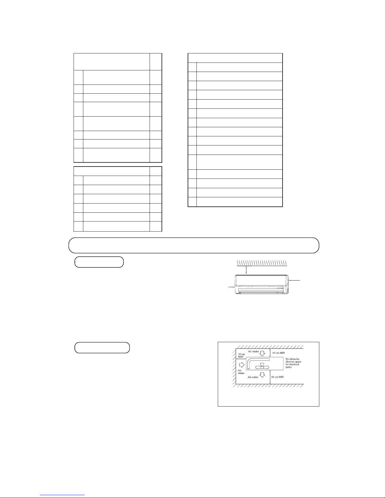
⑤ Blowing out port and suction port on the back side of the unit can be installed at a distance of 10cm from walls.
(In case the barrier is 1.2m or above in height, or is overhead, the sufficient space between the unit and wall shall be secured.)
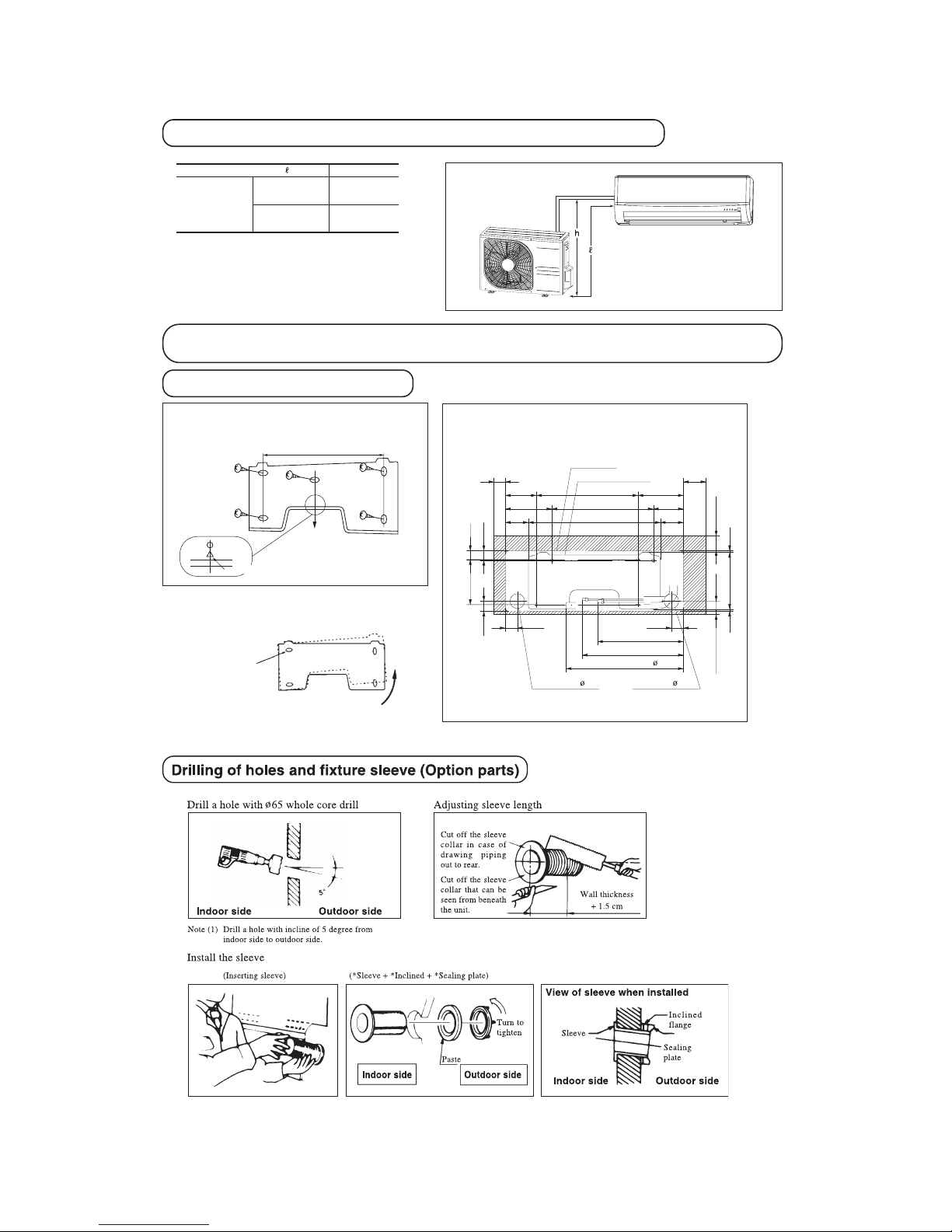
⑥ When the unit is installed, the space of the following dimension and above shall be secured.
OUTDOOR UNIT
Note (1) If the wall is h igher than 1.2 m or a ceiling is
present, distances larger than indicated in the above
table must be provided.
Selection of installation location
① Where there is no obstructions to the air flow and where the
cooled air can be evenly distributed.
② A solid place where the unit or the wall will not vibrate.
③ A place where there will be enough space for servicing. (Where
space mentioned right can be secured)
④ Where wiring and the piping work will be easy to conduct.
⑤ The place where receiving part is not exposed to the direct rays of
the sun or the strong rays of the street lighting.
⑥ A place where it can be easily drained.
⑦ A place separated at least 1m away from the television or the ra-
dio.
(To prevent interfence to images and sounds.)
INDOOR UNIT
Left
side
Right
side
14.0 ~ 61. 0N · m
(1.4 ~ 6.1 kgf · m)
( )
Designed s pecifically
for R22
( )
Designed s pecifically
for R22
( )
Designed s pecifically
for R22
( )
Designed s pecifically
for R22
( )
Designed s pecifically
for R22
10 cm
5 cm
10 cm
-
20
-
'12•SRK-T-137
Installation of indoor unit
Installation of installation board
• Adjustment of the installation board in the horizontal
direction is to be conducted with five screws in a
temporary tightened state.
• Adjust so that board will be level by turning
the board with the standard hole as the center.
Standard hole
Look for the inside wall structures (Intersediate support or
pillar and firaly install the unit after level surface has been
checked.)
Mating mark for level surface
450
INSTALLATION SPACE (INDOOR UNIT) (FRONT VIEW)
Unit : mm
Piping hole( 65) Piping hole( 65)
Installation board
Indoor unit
53.5
Piping for Gas 380.6
Piping for Liquid 448.6
Drain hose 520( 16)
53.5
Space
for service*
Space
for service
44.5
252.2
7.5
8.3
Space for
service
50
Space for
service
100
102.5
585
102.5
133.5
450206.5
202450138
44.5
43.2
39.3
200
100
15
Limitations for one way piping length and vertical height difference
One way piping length ( ) 15 m
Outdoor
unit is lower
5 m
Outdoor unit
is higher
5 m
Vertical height
difference (h)
* Leave extra space on the right side to enable removal of the lid screw.
-
21
-
'12•SRK-T-137
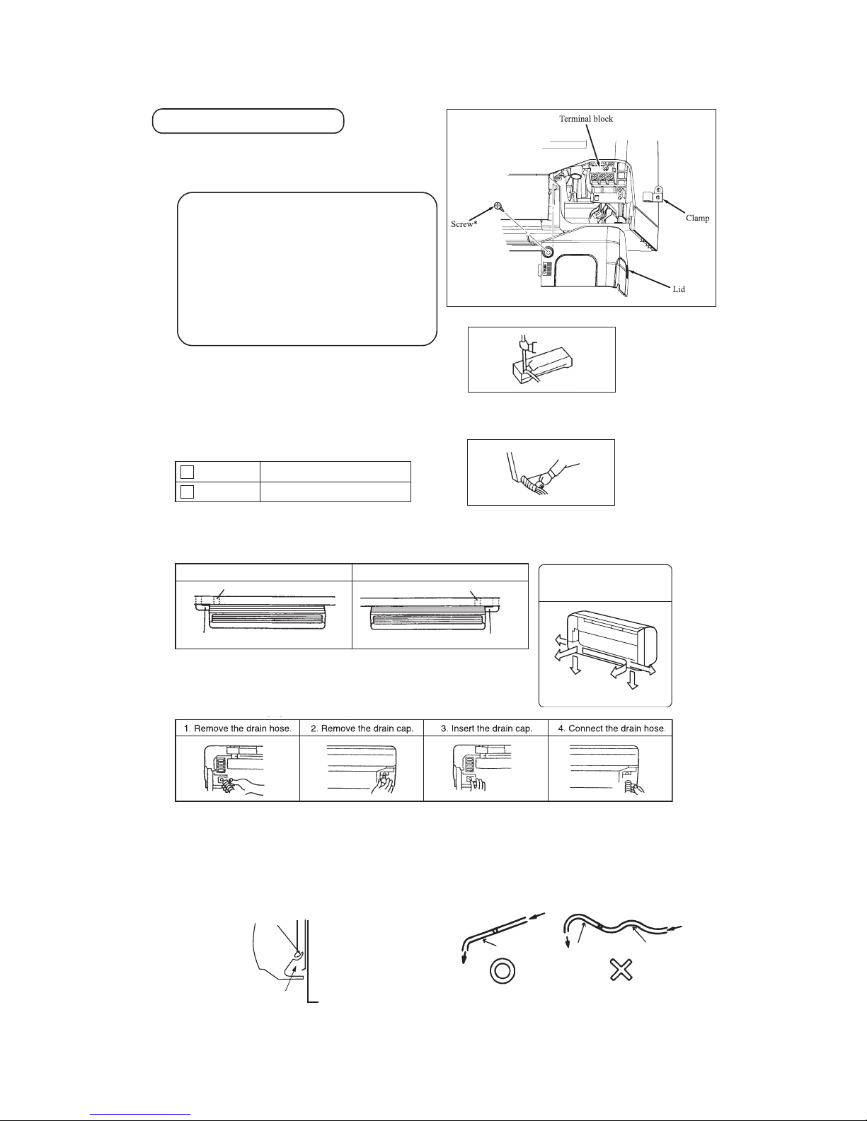
Preparation of indoor unit
Pipe
Drain hose
① Mounting of connecting wires
ⓐ Remove the lid.
ⓑ Remove the wiring clamp.
ⓒ Connect the connecting wire securely to the terminal block.
Use cable for interconnection wiring to avoid loosening of the
wires.
CENELEC code for cables Required field cables.
H05RNR3G1.5 (Example) or 245IEC57
H Harmonized cable type
05 300/500 volts
R Natural-and/or synth. rubber wire insulation
N Polychloroprene rubber conductors insulation
R Standed core
4or5 Number of conductors
G One conductor of the cables is the earth conductor (yel-
low/green)
1.5 Section of copper wire (mm
2
)
• Connect the connection wire securely to the terminal block.
If the wire is not affixed completely, contact will be poor,
and it is dangerous as the terminal block may heat up and
catch fire.
• Take care not to confuse the terminal numbers for indoor and
outdoor connections.
• Affix the connection wire using the wiring clamp.
ⓓ Fix the connecting wire by wiring clamp.
ⓔ Attach the lid.
ⓕ Close the air inlet panel.
For power supply, indoor outdoor
For power supply, indoor outdoor
1 Brown
2 Blue
② Shaping the pipe
③ Taping of the exterior
• Hol d the bottom of the pipe and change its direction befor e stretching it and shap ing it.
• Tap e only the p ortion that runs throug h the wall .
Always ta pe the cros sover wires with the p ipe.
④ Cautions when piping from the left and the rear center of the unit
[ Top View ]
• L oose n and r emov e the
spring-typ e clamp.
• Rem ove with your hand or
a pair of pliers.
• Use a hexagonal wrench to
correctly insert the drain cap
which was removed in 2.
Caution: Be careful because
if th e cap i s not i nse rted
pro perty , water l eak may
occur.
• Lo osen the spring-type clamp
and sec urely inse rt the drai n
hose.
Caution: Be care ful because if
the drai n hos e is not i nsert ed
properly, wa ter leak ma y occur.
gnipiP ediS thgiRgnipiP ediS tfeL
Right rear pipingLeft rear piping
gnipip edis thgiRgnipip edis tfeL
Left downward
Right
Rear
Downward
Left rear
Left
Piping is possible in the rear,
left, left rear, left downward,
right or downward direction.
• Do not place t he power su pply cords above the gutter, bec ause the
air conditioner is structur ed i n a way wh ere condensati on o n th e
back side is collect ed in to th e drain pan before dra inage.
• Do not make tr aps in the drain hose line.
Declining slope
Inverted s lipe
Trap
* Leave space to allow
removal of this screw
after installation.
[ Procedure for exchanging the drain hose ]
Wall
Gutter
Pipes storage area
-
22
-
'12•SRK-T-137
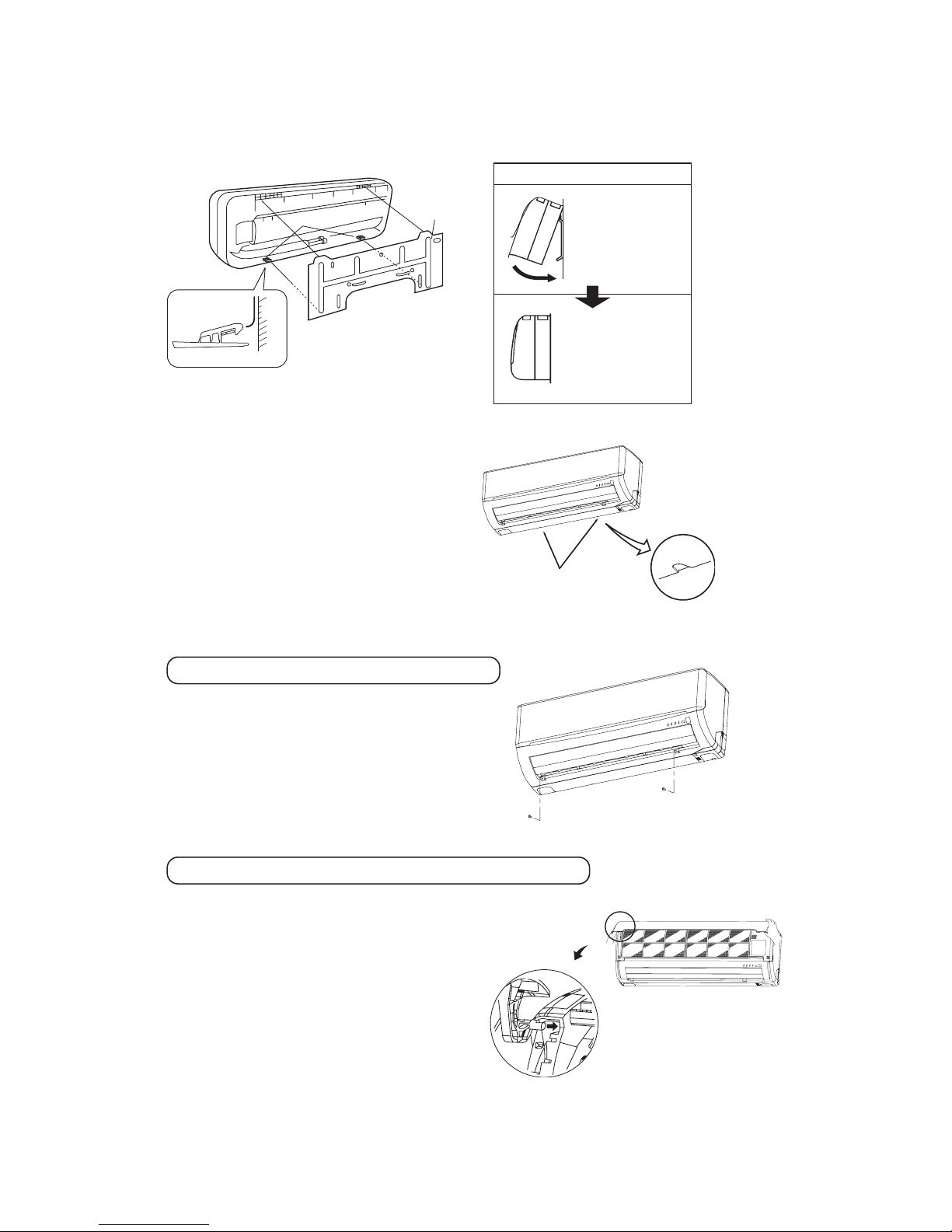
Installing steps
1.Hook the upper part
of the indoor unit to
the installation board.
2.The unit can be installed
simply by gently pushing in the lower part.
⑤ Securing the indoor unit to the installation board
Wall
Indoor un it base low er latch
Installati on board
Latch (2 l ocations)
Installati on
board
Indoor uni t
•
How to remove the indoor unit from the installation board
① Push up at the marked portion of the indoor unit base
lower latch, and slightly pull it toward you.
(both right and left hand sides)
(The indoor unit base lower latch can be removed
from the installation board)
② Push up the indoor unit upward. So the indoor unit
will be removed from the installation board.
Removal and installation of the front panel
Open/close and detachment/attachment of air inlet panel
Set screw s
① Removing
• Remove the 2 set screws.
• Mov e the lower part of the panel forward and push
upwards to remove. (Remove the 3 latches in the upper
section.)
② Fitting
• Do remove the air filter.
• Cover the body with the front panel.
• Push the circled portion at the front.
• Tighten the 2 set screws.
• Fit the air filter. Carry out in the above order.
① To open, pull the panel at both ends of lower part and
rel ease lat ches, then pull up th e panel unt il you feel
resistance. (The air inlet panel stops at approx. 60˚ open
position.)
② To close, hold the panel at both ends of lower part to lower
downward and push it slightly until the latch works, then
push the center portion slightly.
③ To remove, pull up the panel to the position shown in right
illustration and pull it toward you.
④ To install, insert the air inlet panel arm into the slot on the
front panel from the position shown in right illustration,
hold the panel at both ends of lower part, lower it downward
slow ly, then push it slightly until the latch works and
further push the center portion slightly.
The marke d portion o f the
indoor un it base low er latch
-
23
-
'12•SRK-T-137
1 2
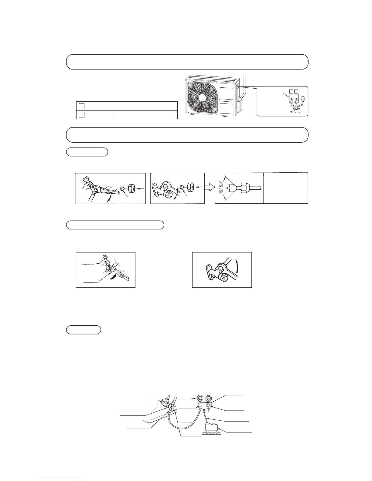
Installation of outdoor unit
For power supply, indoor outdoor
For power supply, indoor outdoor
1 Brown
2 Blue
① Make sure that the unit is stable in installation. Fix the unit
to stable base.
② Perfrom wiring, making wire terminal numbers conform to
terminal numbers of indoor unit terminal block.
Terminal block
Interconne cting wi re
Connection of refrigerant pipings
Preparation
Connection of refrigerant piping
Air purge
Keep the openings of the pipes covered with tapes etc. to prevent dust, sand, etc. from entering them.
• Specified torquing value:
Liquid side (ø6.35) : 14~18N·m (1.4~1.8kgf·m)
Gas side (ø9.52) : 34~42N·m (3.4~4.2kgf·m)
Gas side (ø12.7) : 49~61N·m (4.9~6.1kgf·m)
• Use one more spanner to fix the valve.
① Tighten all flare nuts in the pipings both indoor and outside wall so as not to cause leak.
② Connect service valve, charge hose, manifold valve and vacuum pump as is illustrated below.
③ Open manifold valve handle Lo to its full width, and perform vacuum or evacuation.
Continue the vacuum or evacuation operation for 15 minutes or more and check to see that the vacuum gauge reads – 0.1 MPa
(– 76 cmHg).
④ After completing vacuum operation, fully open service valve (Both gas and liquid sides) with hexagon headed wrench.
⑤ Detach the charge hoses.
⑥ Check for possible leakage of gas in the connection parts of both indoor and outdoor.
• Remo ve the flar ed nuts.
(on both liquid and gas sides)
• Rem ove the fla red nuts.
(on both l iquid and ga s sides)
• Inst all the remov ed flared nuts t o the pipes to be connected, th en flare t he pipes.
Dimension A
Liquid si de
(ø6.35): 9.0 dia
Gas side
(ø9.52): 13.0 di a
(ø12.7): 16.2 d ia
Press
Remove
Remove
(Do not
turn)
Spanner
for fixing
the piping )
Torque
wrench
• Specified torquing value:
Liquid side (ø6.35) : 14~18N·m (1.4~1.8kgf·m)
Gas side (ø9.52) : 34~42N·m (3.4~4.2kgf·m)
Gas side (ø12.7) : 49~61N·m (4.9~6.1kgf·m)
① Indoor unit side
② Outdoor unit side
① Indoor unit side ② Outdoor unit side
• Connect firmly gas and liquid side
pipings by Torque wrench.
• Connect firmly gas and liquid side
pipings by Torque wrench.
• Always use a Torque wrench and back up spanner to tighten the flare nut.
Manifol d
Valve
-76 cm Hg
Handle Lo
(pressure )
Charge ho se
Stop valv e
(Two-way valve)
Service p ort
Stop value
(Three- way
value)
Compound
(Gauge)
Pressure
gauge
Handle Hi
(pressure)
Charge ho se
Vacuum pu mp
-
24
-
'12•SRK-T-137
When refrigerant piping exceeds 7.5m conduct additional refrigerant charge after refrigerant sweeping.
7.5m over 15m:Additional charge amount per meter = 10g/m
[Example]
How much amount of additional charge for 15m piping?
(15 – 7.5)m × 10g/m=75g 75g for additional charge
♦ Additional refrigerant charge
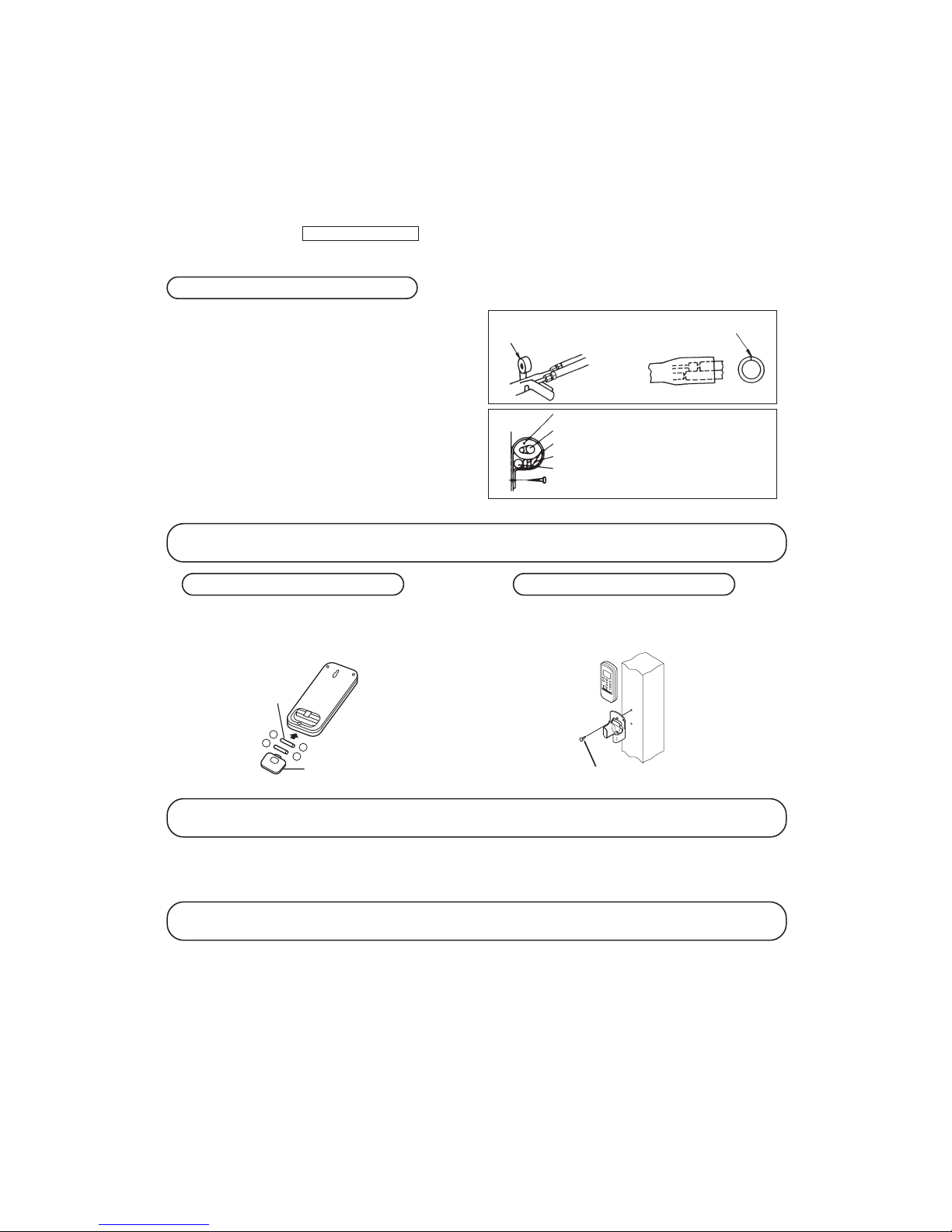
Installation of wireless remote control
Insulation of connecting portion
Mounting method of battery
Earthing work
① Cover the connection portion of the refrigerant piping with the
pipe cover and seal them.
If neglecting to do so, moisture occurs on the piping and water
will drip out.
② Finishing and fixing
ⓐ Tie up the piping with wrapping tape, and shape it so that it con-
forms to which the pipe is attached.
ⓑ Fix them with clamps as right figure.
Vinyl tap e
To c over the c onnecting portion with insulation mate rials, cut upper porti on and then seal
it with i nsulation m aterials.
Cover th e exterior portion with cov ering ta pe and sh ape the piping so it
will m atch the contou rs of the route
that the piping to take . Al so fi x th e
wiring and pipi ngs to the wall with
clamps.
Insulation
Refrigeran t piping
Electrica l wiring
Covering tape
Drain hos e
Tapping s crew
-
-
+
+
• Uncover the wireless remote control, and mount the batteries [R03(AAA, Micro)×2 pieces] in the body regularly.
(Fit the poles with the indication marks, ⊕ & ⊖without
fail)
• Earth work shall be carried out without fail in order to prevent electric shock and noise generation.
• The connection of the earth cable to the following substances causes dangerous failures, therefore it shall never be done.
City water pipe, Town gas pipe, TV antenna, lightning conductor, telephone line, etc.
Trial run and operation
① Conduct trial run after confirming that there is no gas leaks.
② When conducting trial run set the remote control thermostat to continuous operation position. However when the power source is cut
off or when the unit’s operation switch is turned off or was turned to fan operation position, the unit will not go into opera tion in
order to protect the compressor.
③ Explain to the customer on the correct usage of the air-conditioner in simple layman’s terms.
④ Make sure that drain flows properly.
Battery
Cover
Fixing to pillar or wall
• Conventionally, operate the wireless remote control by
holding in your hand.
• Avoid installing it on a clay wall etc.
Screws
-
25
-
'12•SRK-T-137
Remote control
1.7
OUTLINE OF OPERATION CONTROL BY MICROCOMPUTER
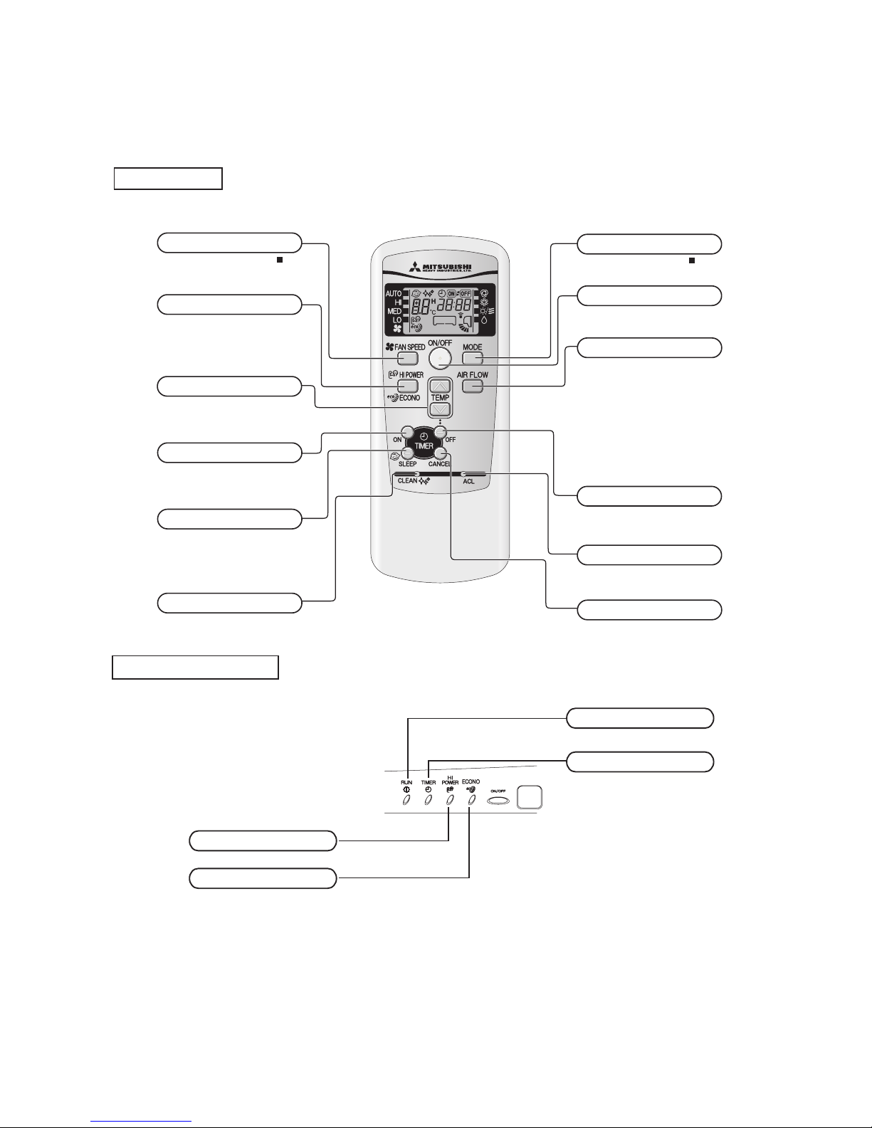
(1) Operation control function by remote control
◆
Operation section
Models SRK10CMV, 13CMV
ECONO light (orange)
Illuminate s during ECO NOMY operati on.
HI POWER light (green)
Illuminate s during H IGH POWER opera tion.
RUN light (green)
Illuminate s during o peration
and CLEAN operation.
TIMER light (yellow)
Illuminate s during TIM ER operatio n.
FAN SPEED button
Each time the button i s pushed, th e
indicator is switche d over in t urn.
HI POWER/ECONO button
This butt on changes the HIGH PO WER/
ECONOMY mo de.
TEMPERATURE Button
This butt on sets the room tempe rature.
(This but ton changes the presen t time and
TIMER time .)
ON TIMER button
This butt on selects ON TIMER op eration.
SLEEP button
This butt on changes to SLEEP op eration.
CLEAN switch
This swic h changes t he CLEAN mo de.
OPERATION MODE select button
Each time the button pushed, th e
indicator is switched over in turn .
ON/OFF (luminous) button
Press for starting o peration, p ress agian
for stoppi ng.
AIR FLOW (UP/DOWN) button
This butto n changes th e air flow ( up/
down) mode .
• The above illustration shows all controls, but in practi ce
only the r elevant parts a re shown.
OFF TIMER button
This butto n selects OFF TIMER o peration.
CANCEL button
This butt on cancels the ON time r, OFF
timer, and SLEEP opera tion.
RESET switch
Switch fo r resetting microcompu ter and
setting t ime.
Unit display section
-
26
-
'12•SRK-T-137
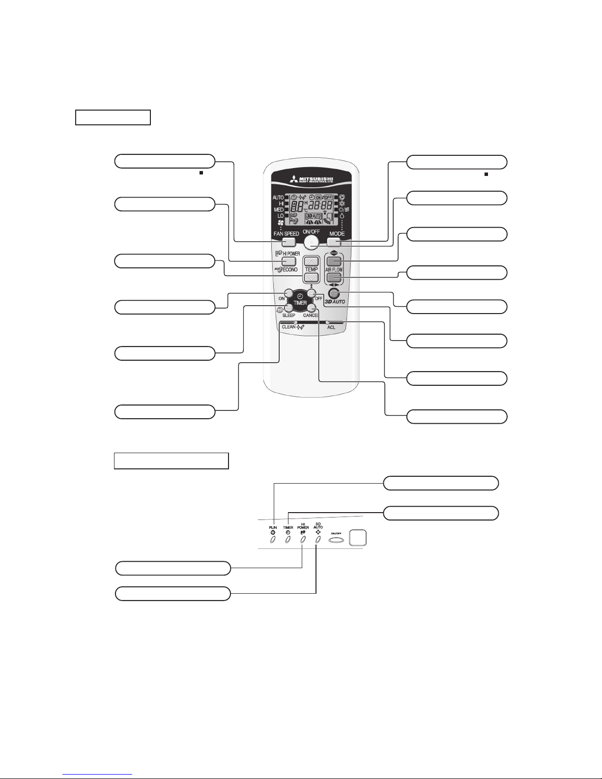
◆
Operation section
Unit display section
Models SRK10CMS, 13CMS
SRK10CMS-2, 13CMS-2
3D AUTO light (green)
Illuminate s during 3D AUTO operation.
HI POWER light (green)
Illuminate s during HI GH POWER opera tion.
RUN light (green)
Illuminate s during op eration
and CLEAN operation.
TIMER light (yellow)
Illuminate s during TIM ER operatio n.
Operation and indication section for remote control
Operation section
SRK10YJV-S
SRK13YJV-S
FAN SPEED button
Each time the button is pushed, the
indicator is switched ov er in turn.
v
The above illustratio n shows all controls, but in practice
only the r elevant par ts are show n.
OPERATION MODE select button
Each time the button push ed, the
indicator is switched ove r in turn.
ON/OFF (luminous) button
Press for sta rting operat ion, press again
for stoppi ng.
HI POWER/ECONO button
This butt on ch anges th e HIG H POW ER/
ECONOMY mo de.
AIR FLOW (UP/DOWN) button
This butto n changes t he air flow (up/down) mode .
This butto n changes t he air flow (left/righ t) mode.
SLEEP button
This butto n changes t o SLEEP ope ration.
CLEAN switch
This switc h changes t he CLEAN mo de.
ON TIMER button
This butto n selects O N TIMER ope ration.
AIR FLOW (LEFT/RIGHT) button
3D AUTO button
Thi s b utto n set s 3D AUTO ope ratio n.
Thi s b utto n can cels the ON t imer, OFF
timer, and SLE EP operatio n.
CANCEL button
RESET switch
Switch for resetting microcomput er and
setting ti me.
OFF TIMER button
This butto n selects O FF TIMER op eration.
TEMPERATURE button
This butto n sets the room temper ature.
(This butt on changes the pre sent time a nd
TIMER time .)
Remote control
-
27
-
'12•SRK-T-137
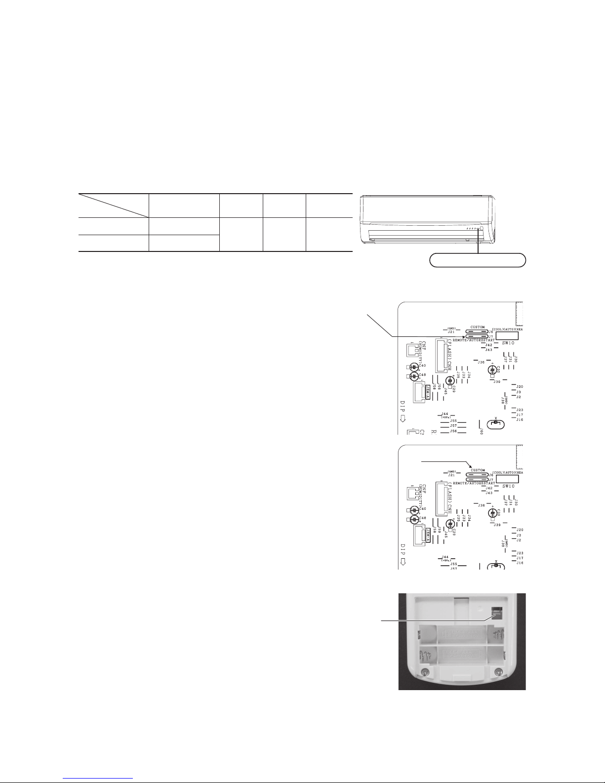
(2) Unit ON/OFF button
When the remote control batteries become weak, or if the remote control is lost or malfunctioning, this button may be used to turn the
unit on and off.
(a) Operation
Push the button once to place the unit in the automatic mode. Push it once more to turn the unit off.
(b) Details of operation
The unit will go into the automatic mode in which it automatically determines, from room temperature (as detected by sensor),
whether to go into the cooling or thermal dry modes.
(3) Auto restart function
(a) Auto restart function records the operational status of the air-conditioner immediately prior to be switched off by a power cut,
and then automatically resumes operations after the power has been restored.
(b) The following settings will be cancelled:
(i) Timer settings
(ii) HIGH POWER operations
Notes (1) Auto restart function is set at on when the air-conditioner is shipped from the factory. Consult
with your dealer if this function needs to be switched off.
(2) When power failure ocurrs, the timer setting is cancelled. Once power is resumed, reset the timer.
(3)
If the jumper wire (J7) “AUTO RESTART” is cut, auto restart is disabled. (See the diagram at right)
(4) Custom cord switching procedure
If two wireless remote control are installed in one room, in order to prevent wrong operation
due to mixed signals, please modify the printed circuit board in the indoor unit’s control box
and the remote control using the following procedure. Be sure to modify both boards. If
only one board is modied, receiving (and operation) cannot be done.
(a) Modifying the indoor unit’s printed circuit board
Take out the printed circuit board from the control box and cut off jumper wire (J6)
using wire cutters.
After cutting of the jumper wire, take measures to prevent contact with the other the lead
wires, etc.
(b) Modifying the wireless remote control
(i) Remove the battery.
(ii) Cut the jumper wire shown in the gure at right.
Cut
Function
Operation mode
Room temperature
setting
Fan speed
Flap
Timer switch
COOL
About 23ºC
Auto Auto Continuous
DRY
About 24ºC
Jumper wire (J7)
Jumper wire (J6)
Unit ON/OFF button
In emergen cies, this button c an be used for turni ng on/off the unit when
remote con trol is not availab le.
Page 15
RUN light (green)
Illuminate s during operation
and CLEAN operation.
TIMER light (yellow)
Illuminate s during TIMER oper ation.
Unit ON/OFF button
-
28
-
'12•SRK-T-137
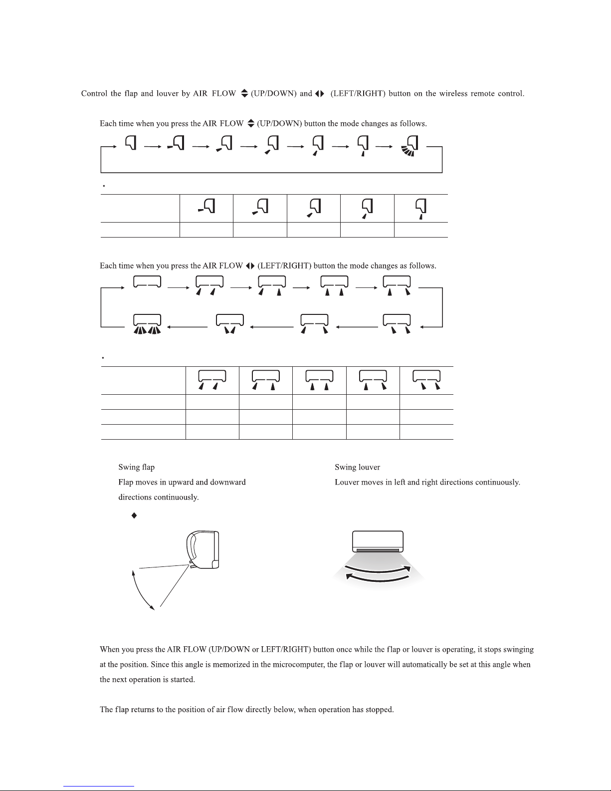
(5) Flap and louver control (Louver control function only CMS and CMS-2 models)
(a) Flap
(b) Louver
(c) Swing
(i)
(d) Memory flap (Flap or Louver stopped)
(e) When not operating
COOL , DRY, FAN
Remote control
display
Approx. 10° Approx. 20° Approx. 30°
(Swing)
(Flap stopped)
Approx. 45° Approx. 60°
Angle of Flap from Horizontal
Center installation
Remote control
display
Right end installation
Left end installation
Angle of Louver
Left Approx. 45°
Left Approx. 45°
Left Approx. 20°
Left Approx. 30°
Center
Left Approx. 20°
Right Approx. 20°
Center
Right Approx. 45°
Right Approx. 20°
Left Approx. 20°
Center
Right Approx. 20° Right Approx. 30° Right Approx. 45°
(Louver stopped)
(Swing) (Spot) (Wide)
In COOL, DRY, FAN operation
Approx.
10°
Approx. 60°
(ii)
-
29
-
'12•SRK-T-137
(6) 3D auto operation (only CMS and CMS-2 models)
Operation step
Flap
Louver
Conditions for
jumping to next STEP
Fan speed Setting fan speed
_
20 cycle 60 cycle 60 cycle
Auto : HIGH POWER
Other than Auto: Setting fan speed
Setting fan speed
STEP1 STEP2 STEP3 STEP4
Left louver
The left louver and right louver
operate in the same direction
left and right.
The left louver and right louver
operate in opposite directions to
each other on the left and right sides.
The left louver and right louver operate in opposite directions to
each other on the left and right sides.
Right louver
Left louver Right louver
Left louver Right louver
1.4.6 3D auto operation
(only SRK10CJV-2, 13CJV-2)
Control the flap and louver by 3D AUTO button on the wireless remote control.
Fan speed and air flow direction are automatically controlled, allowing the entire room to efficiently conditioned.
(a) Detail of operation
(i) Perform STEP1 → STEP2 → STEP3 → STEP4 one time.
(ii) After performing STEP4 in (i) above, the next steps to be carried out are determined by the difference between the room
temperature and the setting temperature.
1) Room temperature – Setting temperature > 5ºC: STEP2 STEP3 →→ STEP4 are performed.
2) Room temperature – Setting temperature
<
5ºC: STEP3
=
→
STEP4 are performed.

-
30
-
'12•SRK-T-137
(b) Sleep timer operation
(7) Timer operation
(a) Comfortable timer setting (ON timer)
(c) OFF timer operation
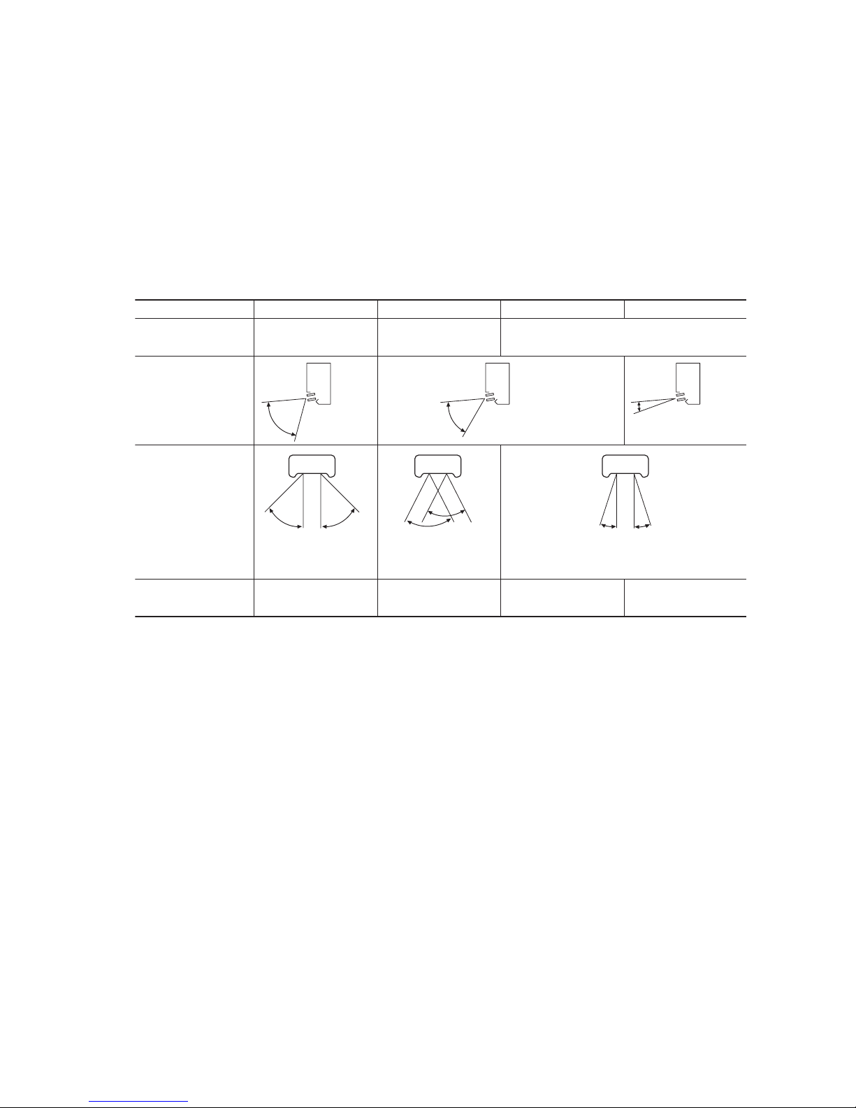
(8) Installation location setting (only CMS and CMS-2 models)
(a) Setting
(i)
If the air conditioning unit is running, press the ON/OFF button to stop.
(ii) Press the AIR FLOW (UP/DOWN) button and the
AIR FLOW
(LEFT/RIGHT) button together for 5 seconds
or more.
(iii) Setting the air-conditioning installation location.
(iv) Press the ON/OFF button.
Airf low range Airf low rangeAirf low range
(Left End Installation) (Center Installation) (Right End Installation)
(Center Installation) (Right End Installation) (Left End Installation)
(i), (iv)
(ii)
(iii)

-
31
-
'12•SRK-T-137
27.5
25.5
19.5
18
30
(9) Outline of cooling operation
(a) Operation of major functional components in Cooling mode
(b) Fan speed switching
ON OFF OFF
ON
OFF OFF
ON ON ON
Thermostat ON Thermostat OFF Failure
Cooling
Compressor
Indoor fan motor
Outdoor fan motor
Auto fan control
Speed 5
Speed 3
Speed 2
Model
Fan speed
All model
Auto
MED
HI
LO
(10) Outline of automatic operation
(a) Determination of operation mode
The unit checks the indoor air temperature and the outdoor air temperature, determines the operation mode, and then begins in
the automatic operation.
Dehumidifying
Cooling
Indoor air temperature (˚C)
Outdoor air temperature (˚C)
(b)
The unit checks the temperature every 30 minutes after the start of operation and, if the result of check is not same as the previ
-
ous operation mode, changes the operation mode.
(c)
When the unit is started again within one hour after the stop of automatic operation or when the automatic operation is selected
during cooling or dehumidifying operation, the unit is operated in the previous operation mode.
(d)
Setting temperature can be adjusted within the following range. There is the relationship as shown below between the signals of
the wireless remote control and the setting temperature.
Signals of wireless remote control (Display)
–6 –5 –4 –3 –2 –1
±
0 +1 +2 +3 +4 +5 +6
Setting
Cooling
17 18 19 20 21 22 23 24 25 26 27 28 29
temperature
Dehumidifying
18 19 20 21 22 23 24 25 26 27 28 29 30

-
32
-
'12•SRK-T-137
(11) Protective control function
(a) Frost prevention for indoor heat exchanger (During cooling or dehumidifying)
(i) Operating conditions
1) Indoor heat exchanger temperature (Th2) is lower than 2.5ºC.
2) 3 minutes elapsed after the start of operation.
(ii) Detail of frost prevention operation
Compressor OFF
Indoor fan Protects the fan tap just before frost prevention control.
Outdoor fan Depending on the stop mode
(iii) Reset condition: Indoor heat exchanger temperature (Th2) is higher than 8ºC.
(b) Indoor fan motor protection
When the airconditioner is operating and the indoor fan motor is turned ON, if the indoor fan motor has operated at 300 rpm or
under for more than 30 seconds, the unit enters first in the stop mode and then stops the entire system.
TIMER light illuminates simultaneously and the RUN light flashing 6-time at each 8-second.
(c) 3 minutes forced operation
When the compressor begins operating the thermal operation is not effective for 3 minutes, so operation continues as is in the
operation mode. (After 3 minutes has passed the thermal operation is effective.)
However, stopping the compressor via a stop signal or protection control has priority.
(d) Abnormality of outdoor unit
When the indoor heat exchanger temperature does not fall to 25°C or below for 40 minutes after 5 minutes have elapsed since
the compressor operation start, the abnormality stop occurs. (RUN light : ON, TIMER light : 2-time flash)
(e) Sensor disconnection (room temperature, indoor heat exchanger
)
(i) Room temperature sensor
If the temperature detected by the room temperature sensor is – 20ºC or lower continuously for 15 seconds or longer while
operation is stopped, an error indication is displayed. (RUN light: 2-time flash, TIMER light: ON)
(ii) Indoor heat exchanger temperature sensor
If the temperature detected by the indoor heat exchanger temperature sensor is –20ºC or lower continuously for 15 seconds
or longer while operation is stopped, an error indication is displayed.
(RUN light : 1-time flash, TIMER light : ON)

-
33
-
'12•SRK-T-137
1.8 MAINTENANCE DATA
(1) Cautions
(a) If you are disassembling and checking an air conditioner, be sure to turn off the power before beginning. When working on
indoor units, let the unit sit for about 1 minute after turning off the power before you begin work. When working on an outdoor
unit, there may be an electrical charge applied to the main circuit (electrolytic condenser), so begin work only after discharg-
ing this electrical charge (to DC 10 V or lower).
(b) When taking out printed circuit boards, be sure to do so without exerting force on the circuit boards or package components.
(c) When disconnecting and connecting connectors, take hold of the connector housing and do not pull on the lead wires.
(2) Items to check before troubleshooting
(a) Have you thoroughly investigated the details of the trouble which the customer is complaining about?
(b) Is the air conditioner running? Is it displaying any self-diagnosis information?
(c) Is a power supply with the correct voltage connected?
(d) Are the control lines connecting the indoor and outdoor units wired correctly and connected securely?
(e) Is the outdoor unit’s service valve open?
(3) Troubleshooting procedure (If the air conditioner does not run at all)
If the air conditioner does not run at all, diagnose the trouble using the following troubleshooting procedure. If the air condi-
tioner is running but breaks down, proceed to troubleshooting step (4).
Important
When all the following conditions are met, we say that the air conditioner will not run at all.
(a) The RUN light does not light up.
(b) The aps do not open.
(c) The indoor unit fan motors do not run.
(d) The self-diagnosis display does not function.
YES
YES
YES
NO
NO
NO
NO
YES
Troubleshooting procedure (If the air conditioner does not run at all)
Is the cor rec t v olt age
connected for the power
supply?
With the power off, do
the aps open manually,
then close again when
the power is turned on?
Is the r e a re c e pt i o n
sound emitted from the
unit when it is operated
by the remote control?
Replace the indoor PCB and
perform an operation check.
Make sure the correct voltage is connected, then perform an operation check.
Is the current fuse on the indoor unit PCB blown?
Proceed to the indoor PCB
check.
Proceed to the wireless remote
control troubleshooting procedure.
If the package components
are not damaged, replace
the fuse and perform an operation check again.
* If the voltage is correct, it will be
within the following voltage range.
AC 198 ~ 264 V

-
34
-
'12•SRK-T-137
(4) Troubleshooting procedure (If the air conditioner runs)
NO
NO
NO
NO
YES
YES
YES
YES
Note (1) Even in cases where only intermittent stop data are generated, the air conditioning system is normal. However, if the same protective operation recurs
repeatedly (3 or more times), it will lead to customer complaints. Judge the conditions in comparison with the contents of the complaints.
Conrm the contents of the customer complaint.
Check the self-diagnosis display.
Eliminate the cause of the trouble and perform an
operation check.
Replace the faulty component, then perform an
operation check.
Identify the faulty component by using the check
procedure corresponding to the content of the trouble.
The cause of the trouble can
be specically identied.
See below.
NO
YES
(5) Self-diagnosis table
When this air conditioner performs an emergency stop, the reason why the emergency stop occurred is displayed by the ashing of
display lights. If the air conditioner is operated using the remote control 3 minutes or more after the emergency stop, the trouble
display stops and the air conditioner resumes operation.
(1)
Notes (1) The air conditioner cannot be restarted using the remote control for 3 minutes after operation stops.
When a heat exchanger sensor wire disconnection is detected while operation is
stopped. (If a temperature of –20ºC or lower is detected for 15 seconds, it is
judged that the wire is disconnected.)
(Not displayed during operation.)
When a room temperature sensor wire disconnection is detected while operation
is stopped. (If a temperature of –20ºC or lower is detected for 15 seconds, it is
judged that the wire is disconnected.)
(Not displayed during operation.)
• Broken heat exchanger sensor
wire, poor connector
connection
• Indoor PCB is faulty
• Broken room temperature
sensor wire, poor connector
connection
• Indoor PCB is faulty
When conditions for turning the indoor unit’s fan motor on exist during air
conditioner operation, an indoor unit fan motor speed of 300 rpm or lower is
measured for 30 seconds or longer. (The air conditioner stops.)
• Defective fan motor, poor
connector connection
ON
1-time
flash
ON
2-time
flash
ON
6-time
flash
When there is an emergency stop caused by trouble in the outdoor unit, or the
input current value is found to be lower than the set value.
(The air conditioner stops.)
• Broken compressor wire
• Compressor blockage
•
52C relay in indoor PCB is faulty
• Improper wire connection
between indoor and outdoor
2-time
flash
ON
Indoor unit display panel
Cause Display (flashing) condition
RUN
light
TIMER
light
Heat exchanger
sensor error
Room
temperature
sensor error
Indoor fan
motor error
Trouble of
outdoor unit
Description
of trouble

-
35
-
'12•SRK-T-137
(6) Inspection procedures corresponding to detail of trouble
Sensor error
[Broken sensor wire,
connector poor connection]
Is connector connection good?
YES
YES
NO
NO
Replace PCB.
Correct connection.
Replace sensor.
Is sensor resistance value good?
(Short circuit)
(Broken wire)
◆
S ensor tempe r ature char a cteri s tics
(Room temp., indoor heat exchanger temp.)
Temperature (˚C)
Resistance (k
Ω
)
30
25
20
15
10
5
30
20
10
40 50 60
70
0
-
10
Indoor fan motor error
[Defective fan motor, connector poor
connection, defective indoor PCB]
Is connector connection good?
YES
NO
Is the output of the indoor unit
PCB normal?
Power supply reset
Correct connector connection
Is normal state restored?
Malfunction by temporary
noise
NO
Replace fan motor (If anomaly
persiste after replacing fan motor,
replace indoor PCB)
YES
Replace indoor PCB
NO

-
36
-
'12•SRK-T-137
Trouble of outdoor unit
[Compressor malfunction of
insufficient gas (refrigerant)]
Does compressor operation?
Is capacitor for compressor normal?
Replace compressor.
Replace heat exchanger sensor
Insufficient gas
Is refrigerant amount normal?
Is heat exchanger sensor resistance
value good?
Is connector for compressor connection
good?
Does trouble persist after charging gas?
Clogged capillary tube or strainer,
defective EEV, etc.
Replace capacitor for compressor.
Correct connection
Check if there are any places where
gas is leaking
YES
YES
NO NO
NO
NO
NO
NO
YES
YES
YES
YES
(8) Checking the indoor electrical equipment
(a) Indoor PCB check procedure
Is there voltage at power source?
(AC 220/230/240V)
Replace PCB
Inspect power source.
If the packag e co mponents
are not damaged, replace the
fuse and perform an operation
check again.
Is the fuse burnt out? (3.15 A)
NO
YES
NO
YES
(7) Phenomenon observed after shortcircuit, wire breakage on sensor
(a) Indoor unit
Phenomenon
Sensor
Shortcircuit
Broken wire
Cooling
Release of continuous compressor operation command
Cooling
System can be operated normally.
Operation
mode
Continuous compressor operation command is not released.
Continuous compressor operation command is not released.
(Anti-frosting)
Heat exchanger
sensor
Room temperature
sensor

-
37
-
'12•SRK-T-137
(9) How to make sure of wireless remote control
(1)
Is remote
contro l norm al?
YES
Again pushing
operating switch
Operating the unit?
NO
Does ON/OFF button
of indoor unit operates?
Operating the unit.
NO
NO
YES
YES
Remote control
defects
Abnormality is not
found.
Replace the display
of indoor unit.
Control problem on
main unit
Is the unit
operable with remote
control?
Defective remote
control
NO
YES
Normal
Note (1) Check method of remote control
(a) Press the reset switch of the remote control.
(b) If all LCD are displayed after one (1) display, it is basically normal.

-
38
-
'12•SRK-T-137
( )
2. SRK19CMS, 25CMS
WALL MOUNTED TYPE
RESIDENTIAL AIR-CONDITIONER
Split system, air cooled
cooling only type
'10 • SRK-T-099
CONTENTS
2.1 SPECIFICATIONS .................................................................................. 41
(2) Outdoor units .................................................................................... 44
(3) Wireless remote control
.................................................................... 45
...................................................................... 43
(1) Indoor units ....................................................................................... 43
2.2 EXTERIOR DIMENSIONS
2.3 ELECTRICAL WIRING ........................................................................... 46
(1) Indoor units ....................................................................................... 46
(2) Outdoor units .................................................................................... 47
...................................................... 50
2.5 RANGE OF USAGE & LIMITATIONS
2.4 PIPING SYSTEM ...................................................................................... 49
.............................................................................. 52
2.6 APPLICATION DATA
2.7 OUTLINE OF OPERATION CONTROL BY MICROCOMPUTER ........... 61
(6) 3D auto operation
............................................................................. 64
(7) Timer operation
................................................................................. 65
...................................................... 62
(1) Operation control function by remote control
(5) Flap and louver control ..................................................................... 63
(4) Custom cord switching procedure
........................................................................ 62(3) Auto restart function
(2) Unit ON/OFF button
.......................................................................... 62
..................................... 61
(8) Installation location setting ................................................................. 65
(10) Outline of automatic operation .......................................................... 66
(9) Outline of cooling operation .............................................................. 66
(11) Protective control function
.................................................................. 67
..................... 70
............................................................................. 69
(4) Troubleshooting procedure (If the air conditioner runs)
(3) Troubleshooting procedure
(If the air conditioner does not run at all)
....... 69
(1) Cautions
............................................................................................ 69
(2) Items to check before troubleshooting ................................................ 69
(5) Self-diagnosis table ............................................................................ 71
(6) Inspection procedures corresponding to detail of trouble ................... 72
2.8 MAINTENANCE DATA

-
39
-
'12•SRK-T-137
'10 • SRK-T-099
CONTENTS
2.1 SPECIFICATIONS .................................................................................. 41
(2) Outdoor units .................................................................................... 44
(3) Wireless remote control
.................................................................... 45
...................................................................... 43
(1) Indoor units ....................................................................................... 43
2.2 EXTERIOR DIMENSIONS
2.3 ELECTRICAL WIRING ........................................................................... 46
(1) Indoor units ....................................................................................... 46
(2) Outdoor units .................................................................................... 47
...................................................... 50
2.5 RANGE OF USAGE & LIMITATIONS
2.4 PIPING SYSTEM ...................................................................................... 49
.............................................................................. 52
2.6 APPLICATION DATA
2.7 OUTLINE OF OPERATION CONTROL BY MICROCOMPUTER ........... 61
(6) 3D auto operation
............................................................................. 64
(7) Timer operation
................................................................................. 65
...................................................... 62
(1) Operation control function by remote control
(5) Flap and louver control ..................................................................... 63
(4) Custom cord switching procedure
........................................................................ 62(3) Auto restart function
(2) Unit ON/OFF button
.......................................................................... 62
..................................... 61
(8) Installation location setting ................................................................. 65
(10) Outline of automatic operation .......................................................... 66
(9) Outline of cooling operation .............................................................. 66
(11) Protective control function
.................................................................. 67
..................... 70
............................................................................. 69
(4) Troubleshooting procedure (If the air conditioner runs)
(3) Troubleshooting procedure
(If the air conditioner does not run at all)
....... 69
(1) Cautions
............................................................................................ 69
(2) Items to check before troubleshooting ................................................ 69
(5) Self-diagnosis table ............................................................................ 71
(6) Inspection procedures corresponding to detail of trouble ................... 72
2.8 MAINTENANCE DATA

-
40
-
'12•SRK-T-137
'10 • SRK-T-099
(9) How to make sure of wireless remote control ..................................... 77
(7)
Phenomenon observed after shortcircuit, wire breakage on sensor
........ 75
(8) Checking the indoor electrical equipment
.......................................... 76
■How to read the model name
Example: SRK 19 C
Series code
Cooling only type
Product capacity
Model name SRK : Wall mounted type
SRC : Outdoor unit
MS

-
41
-
'12•SRK-T-137
2.1 SPECIFICATIONS
Model
Item
SRK19CMS
Indoor unit SRK19CMS Outdoor unit SRC19CMS
Cooling capacity (1) W 5300
Power supply 1 Phase, 220V, 50Hz
Operation
data (1)
Power
consumption
Cooling kW 1.495
Running
current
Cooling
A
7.0
Inrush current 33
COP Cooling 3.55
Noise
level
Cooling
Sound level dB(A) Hi : 47 Me : 42 Lo : 39 50
Power level dB 60 65
Exterior dimensions (Height x Width x Depth) mm 318 x 1098 x 248 640 x 850 x 290
Exterior appearance
(Munsell color)
Fine snow
(8.0Y 9.3/0.1) near equivalent
Stucco white
(4.2Y 7.5/1.1) near equivalent
Net weight kg 17 46
Refrigerant
equipment
Compressor type & Q'ty — RH277VHST(Rotary type) x 1
Motor (Starting method) kW — 1.3 (Line starting)
Refrigerant oil 0.52 (DIAMOND MS56)
Refrigerant (3) kg R22 1.25 (Pre-Charged up to the piping length of 7m)
Heat exchanger Louver fins & inner grooved tubing M fins & inner grooved tubing
Refrigerant control Capillary tubes + Electronic expansion valve
Deice control Microcomputer control
Air handling
equipment
Fan type & Q'ty Tangential fan x 1 Propeller fan x 1
Motor W 56 41
Air flow Cooling m3/min Hi : 18.0 Me : 15.5 Lo : 13.0 38
Fresh air intake Not possible —
Air filter, Quality / Quantity Polypropylene net (washable) x 2 —
Shock & vibration absorber — Cushion rubber (for compressor)
Operation
control
Operation switch Wireless-Remote control —
Room temperature control Microcomputer thermostat —
Operation Display
RUN : Green, TIMER : Yellow, HI POWER : Green,
3D AUTO : Green
Safety devices
Compressor overheat protection,
Frost protection, Serial signal error protection, Fan motor error protection,
Installation
data
Refrigerant piping size (O.D) mm Liquid line: φ6.35 (1/4") Gas line: φ15.88 (5/8")
connecting method Flare connecting
Attached length of piping m
Liquid line : 0.70
Gas line : 0.63
—
Insulation for piping Necessary (Both sides), independent
Refrigerant line (one way) length
m
Max. 25
Vertical height difference between
outdoor unit and indoor unit
Max.15 (Outdoor unit is higher)
Max.15 (Outdoor unit is lower)
Drain hose Connectable (VP 16) —
Power cable 2m (3 Cores wih Earth)
Recommended breaker size A 20
Connection wiring
Size x Core number 1.5mm2 x 4 cores (Including earth cable)
Connecting method Terminal block (Screw fixing type)
Accessories (included)
Mounting kit
Option parts —
Note (1) The data are measured at the following conditions.
Item
Operation
Indoor air temperature Outdoor air temperature
Standards
DB WB DB WB
Cooling 27˚C 19˚C 35˚C 24˚C JIS C 9612, TISI 1155, 2134, 812
(2) This air-conditioner is manufactured and tested in conformity with the TISI.
(3) The operation data are applied to the 220V districts respectively.
(4) The refrigerant quantity to be charged includes the refrigerant in 7m connecting piping.
(Purging is not required even for the short piping.)
The pipe length is 7.5m.

-
42
-
'12•SRK-T-137
Model
Item
SRK25CMS
Indoor unit SRK25CMS Outdoor unit SRC25CMS
Cooling capacity (1) W 7200
Power supply 1 Phase, 220V, 50Hz
Operation
data (1)
Power
consumption
Cooling kW 2.12
Running
current
Cooling
A
9.8
Inrush current 45
COP Cooling 3.40
Noise
level
Cooling
Sound level dB(A) Hi : 50 Me : 46 Lo : 43 55
Power level dB 60 67
Exterior dimensions (Height x Width x Depth) mm 318 x 1098 x 248 750 x 880 x 340
Exterior appearance
(Munsell color)
Fine snow
(8.0Y 9.3/0.1) near equivalent
Stucco white
(4.2Y 7.5/1.1) near equivalent
Net weight kg 17 56
Refrigerant
equipment
Compressor type & Q'ty — 2JS386D5CA02 (Rotary type) x 1
Motor (Starting method) kW — 1.8 (Line starting)
Refrigerant oil 0.7 (ATMOS NM56M or SONISO 4GDID)
Refrigerant (3) kg R22 1.05 (Pre-Charged up to the piping length of 7m)
Heat exchanger Slit fins & inner grooved tubing Aluminium heat-exchanger
Refrigerant control Capillary tubes + Electronic expansion valve
Deice control Microcomputer control
Air handling
equipment
Fan type & Q'ty Tangential fan x 1 Propeller fan x 1
Motor W 40 75
Air flow Cooling m3/min Hi : 20.0 Me : 17.0 Lo : 14.0 60
Fresh air intake Not possible —
Air filter, Quality / Quantity Polypropylene net (washable) x 2 —
Shock & vibration absorber — Cushion rubber (for compressor)
Operation
control
Operation switch Wireless-Remote control —
Room temperature control Microcomputer thermostat —
Operation Display
RUN : Green, TIMER : Yellow, HI POWER : Green,
3D AUTO : Green
Safety devices
Compressor overheat protection,
Frost protection, Serial signal error protection, Fan motor error protection,
Installation
data
Refrigerant piping size (O.D) mm Liquid line :φ6.35 (1/4") Gas line :φ15.88 (5/8")
connecting method Flare connecting
Attached length of piping m
Liquid line : 0.70
Gas line : 0.63
—
Insulation for piping Necessary (Both sides), independent
Refrigerant line (one way) length
m
Max. 25
Vertical height difference between
outdoor unit and indoor unit
Max.15 (Outdoor unit is higher)
Max.15 (Outdoor unit is lower)
Drain hose Connectable (VP 16) —
Power cable 2m (3 Cores wih Earth)
Recommended breaker size A 20
Connection wiring
Size x Core number 1.5mm2 x 4 cores (Including earth cable)
Connecting method Terminal block (Screw fixing type)
Accessories (included) Mounting kit
Option parts —
Note (1) The data are measured at the following conditions.
Item
Operation
Indoor air temperature Outdoor air temperature
Standards
DB WB DB WB
Cooling 27˚C 19˚C 35˚C 24˚C ISO-T1 , JIS C 9612
(2) This air-conditioner is manufactured and tested in conformity with the ISO.
(3) The operation data are applied to the 220V districts respectively.
(4) The refrigerant quantity to be charged includes the refrigerant in 7m connecting piping.
(Purging is not required even for the short piping.)
The pipe length is 7.5m.

-
43
-
'12•SRK-T-137
2.2 EXTERIOR DIMENSIONS
(1) Indoor units
Models All model
Outlet for down piping
(Refer to the above view)
Hole on wall for right rear piping
Hole on wall for left rear piping
Gas piping
Outlet for piping(on both side)
Drain hose
Outlet for wiring
Liquid piping
F
G
E
CDB
Symbol
A
(ø65)
VP16
ø6.35(1/4")(Flare)
Content
ø15.88(5/8")(Flare)
(ø65)
D
C
B
A
E
Wireless remote control
G
F
Unit:mm
7753.5
633.5
703.5
792
15
7.7
44.5
44.5
301.8 8.5
5050
450349 299
106886106
65
100
50
49.5
221.5
25
25
(Service space)
(Service space)
(Service space)
Unit
Installation plate
Space for installation and service when viewing from the front
6-5X17.5(Slot hole)
43
4-12X18(Slot hole)
(Service space)
244 610 244
225
46
1098
318
3
248
410904
60
55
19
55
55
43.564
9
60
150
17.3

-
44
-
'12•SRK-T-137
Drain holes
286.4
12
50
290
49.6
43.5
850
203.1
510 136.9
476
Elogated hole
(2-12 x16)
314
12
328
Terminal block
Service valve (Liquid)
ø6.35 (1/4'')
Service valve (Gas)
ø15.88 (5/8'')
Ground
terminal
124
34.6
20
°
20
°
42.7
100.3
15
640
14
(2) Outdoor unit
Model SRC19CMS
Model SRC25CMS
Unit: mm
Terminal block
Service valve (Gas)
Flare fitting ø15.88 (5/8")
Service valve (Liquid)
Flare fitting ø6.35 (1/4")
25.1165.5
30°
30°
48.5103.3
750
24.1
Drain holes
2-ø15
25.8
29.8
87.9880
150580150
61
532
223
60
15
340
61 47.5
19 380 19
418
Unit: mm

-
45
-
'12•SRK-T-137
(3) Wireless remote control
Unit: mm
60
17.3
150
Unit: mm
17.3
150

-
46
-
'12•SRK-T-137
2.3 ELECTRICAL WIRING
(1) Indoor units
Models SRK19CMS, 25CMS
250V
FUSE
3.15A
S/N
VARISTOR
FAN MOTOR
CNU
CNS
INTERFACE KIT
SC-BIKN
J
M
1
3
4
5
6
5
TO OUTSIDE
T
TERMINAL
1
2/N
3
UNIT
BLOCK
L
HEAT
EXCHANGER
BOARD
CIRCUIT
PRINTED
FLAP
LOUVER
RIGHT
MOTOR
LEFT
CNX2
CNX1
M
M
M
5
5
5
LOUVER
MOTOR
MOTOR
RED
WHITE
RED
WHITE
BLACK
BLUE
YELLOW
BLACK
CNG
CNE
DISPLAY
WIRELESS RECEIVER
CNF
BACK-UP SW
2
8
HUMIDITY
SENSOR
HEAT EXCHANGER
SENSOR 1
ROOM TEMP.
SENSOR
t
t
U

-
47
-
'12•SRK-T-137
(2) Outdoor units
Model SRC19CMS
OUTDOOR AIR TEMP. SENSOR
RUNNING CAPACITOR FOR COMPRESSOR
RUNNING CAPACITOR FOR FAN MOTOR
DIODE STACK
DISCHARGE PIPE TEMP. SENSOR
D.S
CC
CFO
Th2
Th3
FAN MOTOR
ELECTRIC EXPANSION VALVE(COIL)
HEAT EXCHANGER SENSOR
COMPRESSOR MOTOR
FMo
EEV
Th1
CM MARK
/GREEN
RD RED
MARK
Y/GN
COLOR
ORANGE
BLACK
BLUE
BK
OR
BL
WH
YL YELLOW
WHITE
YELLOW
COLOR
Y/GN
3
N
2
1
Y/GN
N
L
WH
RD
BK
N
J
L
CM
CC
WH
CM2
S
RD
R
WH
D.S
VARISTOR
250V 3.15A
FUSE
+
-
52X4
52X3
OR
YL
CM1
52X1
BK
YL
11
C
CFO
CNU
BL
793
RD
YL
5
WH
FMo
CNG
Th2
EEV
CNE
Th1
Th3
PRINTED CIRCUIT
BOARD

-
48
-
'12•SRK-T-137
Model SRC25CMS
PRINTED CIRCUIT
BOARD
N
3
2
1
Y/GN
VARISTOR
D.S
CFO
YL
L
N
V
RD
CM2
Y/GN
RD J
WH N
BK L
250V 3.15A
FUSE
WH
CM1
52X1
BK
YL
WH
CC
U
CM
W
WH
BK
YL
OR
RD
52X5
1
52X3
11
9
52X4
3
CNU
7
5
CNE
FMo
BL
EEV
Th3
Th1
CNG
Th2
ELECTRIC EXPANSION VALVE(COIL)
HEAT EXCHANGER SENSOR
OUTDOOR AIR TEMP. SENSOR
DISCHARGE PIPE TEMP. SENSOR
RUNNING CAPACITOR FOR FAN MOTOR
RUNNING CAPACITOR FOR COMPRESSOR
COMPRESSOR MOTOR
DIODE STACK
FAN MOTOR
CFO
Th3
D.S
CC
EEV
Th2
Th1
FMo
CM
BL
RD
OR
MARK
BK
BLUE
ORANGE
RED
BLACK
COLOR COLOR
YELLOW
/GREEN
YELLOWYL
Y/GN
WH
MARK
WHITE
-
+
VARISTOR
YL
V
RD
CM2
RD J
WH N
BK L
250V 3.15A
FUSE
WH
CM1
52X1
BK
YL
WH
U
W
WHBK
YL
OR
RD
52X5
1
52X3
11
9
52X4
3
CNU
7
5
CNE
BL
Th3
Th1
CNG
Th2
Y/GN
T
PRINTED CIRCUIT
BOARD
-
D.S
+
CFO
CC
CM
FMo
EEV
N
3
2
L
1
INDOOR UNIT
POWER SOURCE
220-240V 50Hz
〜
〜

-
49
-
'12•SRK-T-137
2.4 PIPING SYSTEM
Model SRK19CMS
Model SRK25CMS
Outdoor unitIndoor unit
Room temp.
sensor
Humidity
sensor
Heat
exchanger
Flare connecting
Heat
exchanger
sensor
Piping
(Liquid)
ø
6.35
Piping
(Gas)
ø15.88
Check joint
Service valve (Liquid)
Flare connecting
Discharge pipe
temp. sensor
Outdoor air
temp. sensor
Heat
exchanger
Heat exchanger
sensor
Compressor
Capillary tube
Strainer
Accumulator
Service valve
(Gas)
Electronic
expansion valve
Outdoor unitIndoor unit
Room temp.
sensor
Humidity
sensor
Heat
exchanger
Flare connecting
Heat
exchanger
sensor
Piping
(Liquid)
ø
6.35
Piping
(Gas)
Check joint
Service valve (Liquid)
Flare connecting
Discharge pipe
temp. sensor
Outdoor air
temp. sensor
Heat
exchanger
Heat exchanger
sensor
Compressor
Capillary tube
Strainer
Strainer
Accumulator
Service valve
(Gas)
Electronic
expansion valve
ø
15.88

-
50
-
'12•SRK-T-137
2.5 RANGE OF USAGE & LIMITATIONS
Net capacity = Capacity shown on specification Correction factors as follows.
(1) Coefficient of cooling capacity in relation to temperatures
All model
Models
Item
Indoor return air temperature
(
Upper, lower limits
)
Outdoor air temperature
(
Upper, lower limits
)
Refer to the selection chart
Refrigerant line (one way) length
Max. 25m
Max. 15m (Outdoor unit is higher
)
Max. 15m (Outdoor unit is lower
)
Min. 3 minutes
Max. 10 times/h
Min. 85% of rating
Vertical height difference between
outdoor unit and indoor unit
Power source voltage
Voltage at starting
Frequency of ON−OFF cycle
ON and OFF interval
Rating 10%
14 16 18 20 22
15
20
25
30
35
40
0.6
0.7
0.8
0.9
1.0
1.1
1.2
1.3
43
24
ISO-T1 Standard ConditionIndoor air W.B. temperature °C W.B.
Cooling
Applicable range
Coefficient of cooling
capacity in relation
to temperature
Cooling operation
Outdoor air D.B.
temperature
°C D.B.

-
51
-
'12•SRK-T-137
(2) Correction of cooling capacity in relation to one way length of refrigerant piping
How to obtain the cooling capacity
=
Piping length [m]
Cooling
7
1.0
10
0.99
15
0.975
20
0.965
25
0.95
SRK19CMS
SRK19CMS
5150 5021

-
52
-
'12•SRK-T-137
2.6 APPLICATION DATA
Safety precautions
v When install the unit, be sure to check whether the s election of installa tion pla ce, powe r supply specifications, usage limitation (piping
length, h eight differences between indoor and o utdoor units, power supply voltage and etc .) and installation spaces.
v We recommend you to read this “SAFETY PRECAUTIONS” carefully before the installation work in order to gain full advantage of the func-
tions of the unit and to avoid malfunction due to mishandling.
v The precautions described below are divided into
WARNING and CAUTION . The matters with possibilities leading to serious conse-
quences such as death or serious personal injury due to erroneous handling are listed in the WARNING and the matters with possibilities
leading to personal injury or damage of the unit due to erroneous handling including probability leading to serious consequences in some cases
are listed in
CAUTION . These are very important precautions for safety. Be sure to observe all of them without fail.
v Be sure to confirm no anomaly on the equipment by commissioning after completed installation and explain the operating methods as well as the
maintenance methods of this equipment to the user according to the owner’s manual.
v Keep the installation manual together with owner’s manual at a place where any user can read at any time. Moreover if necessary, ask to hand
them to a new user.
v For installing qualified personnel, take precautions in respect to themselves by using suitable protective clothing, groves, etc., and then perform
the installation works.
v Please pay attention not to fall down the tools, etc. when installing the unit at the high position.
v If unusual noise can be heard during operation, consult the dealer.
v Symbols which appear frequently in the text have the following meaning:
Observe instructions
with great care
Strictly prohibited Provide proper earthing
WARNING
v Installat ion must b e carried out by the qualified installer .
If you install the sys tem by yourself, it ma y ca use ser ious tro uble su ch a s
water le aks, elec tric shoc ks, fire and p ersonal i njury, as a res ult of a sy stem
malfunct ion.
v Install t he system in full ac cordance w ith the in struction manual.
Incorrect ins tallation m ay cause bu rsts, perso nal injury, wat er leaks, el ectric
shocks an d fire.
v Be sure t o use only for house hold and r esidence.
If t his appl iance is installed in infe rior env ironment such as machine s hop
and etc., it can cause malfunction.
v
Use the origi nal accessor ies and the spec ified compon ents for insta llation.
If parts ot her than those presc ribed by us are u sed, It may caus e water lea ks,
electric shocks, fi re and per sonal inju ry.
v Install t he unit in a locatio n with goo d support.
Unsuitabl e installat ion location s can cause the u nit to fall and ca use material
damage an d personal in jury.
v Ensure the u nit is st able whe n installed, so t hat it can withstand e arth-
quakes an d strong winds.
Unsuitabl e installat ion location s can cause the u nit to fall and ca use material
damage an d personal in jury.
v Ventilate th e working ar ea well in the ev ent of re frigerant le akage dur -
ing insta llation.
If t he r efrigerant comes into contact with na ked flames, poisonous gas is
produced .
v When insta lling in sma ll rooms, t ake prevent ion measure s not to exc eed
the densi ty limit o f refrige rant in th e event of leakage.
Consult the expe rt about pr evention measures. I f the density o f ref rigerant
exceeds the limit in the event of leakage, lac k of oxygen ca n occu r, whi ch
can cause se rious acci dents.
v After completed installation , c heck th at no refrigera nt leak s f rom th e
system.
If re frigerant leaks into t he roo m and comes into cont act wi th an oven o r
other hot surface, poi sonous gas is produ ced.
v Tighten t he flare n ut by torq ue wrench with spec ified meth od.
If the f lare nut w ere tightened wi th exces s torque , this ma y cause b urst and
refrigera nt leakag e after a long perio d.
v Do not op en the op eration val ves for l iquid li ne and ga s line un til com-
pleted re frigerant piping wo rk, air ti ghtness te st and eva cuation.
If the c ompressor i s ope rated in sta te o f ope ning ope ration valves before
completed connection o f refrig erant pi ping wor k, air can b e sucked i nto refrigerant c ircuit, whic h can cause bust or p ersonal inju ry due to anomalo usly
high pres sure in th e refrige rant.
v Do not put the dra inage pipe dire ctly into d rainage ch annels whe re poi-
sonous ga ses such a s sulphid e gas can occu r.
Poisonous g ases will flo w into the room t hrough drain age pipe and ser iously
affect th e user’s health and safety.
v Ensure th at no a ir ente rs in t he refr igerant circui t when the unit is in-
stalled a nd removed .
If a ir ent ers i n the refrigerant circuit, t he pre ssure in the ref rigerant circuit
becomes t oo high, w hich can cause burs t and pers onal injur y.
v Do n ot pr ocessing, splice the power cord , or sh are a socket wi th ot her
power plu gs.
This may c ause fire o r electri c shock due to de fecting c ontact, defectin g insulation and over-c urrent etc.
v The ele ctrical i nstallatio n mu st be carried o ut by the q ualified electri-
cian i n ac cordance w ith “the norm f or elec trical work” a nd “nat ional
wiring re gulation”, and the s ystem must be connec ted to the dedic ated
circuit.
Power s upply wi th insuf ficient cap acity an d incorr ect func tion don e by i mproper wo rk can cau se electr ic shocks and fire.
v Be sure t o shut off the power before st arting ele ctrical work.
Failure t o shut off the pow er can caus e electric sho cks, unit fail ure or inc orrect func tion of eq uipment.
v Be sur e to use the ca bles co nforme d t o s afet y s tandar d a nd cabl e
ampacity for pow er distrib ution work .
Unconform able cables ca n cause electri c leak, anomalo us heat produc tion or
fire.
v This ap pliance mus t be con nected to ma in powe r suppl y by mean s of a
circuit bre aker or switch (fuse:20 A) with a conta ct separatio n of at least
3mm.
v Wh en p lugg ing t his a pp lia nce, a pl ug co nfo rmi ng t o the n orm
IEC60884- 1 must be use d.
v Use the p rescribed cables for electrical connection , tig hten the cabl es
securely in terminal block a nd re lieve the cab les correctly to pre vent
overloadi ng the ter minal bloc ks.
Loose conn ections or ca ble mounting s can cause an omalous heat prod uction
or fire.
v Arrange the wi ring i n t he co ntrol box so that it ca nnot b e push ed up
further i nto the bo x. Install th e service pane l correct ly.
Incorrect installa tion may r esult in o verheating and fire.
v Be sure t o fix up t he service pa nels.
Incorrect fixing can c ause ele ctric s hocks or fire due to in trusion of d ust or
water.
v Be sure to switch off the power suppl y in the event of installation , inspec-
tion or s ervicing.
If th e p ower s upply is not shut off, t here i s a risk of el ectric shocks, u nit
failure o r personal injury du e to the u nexpected start o f fan.
v Stop the co mpressor before disconnecti ng ref rigerant pipes in ca se of
pump down op eration.
If disconne cting refrig erant pipes in st ate of opening o peration val ves before
compresso r stop ping, air can be s ucked, whi ch can cause bu rst or personal
injury du e to anoma lously hig h pressure in the re frigerant circuit
v Only use prescribed option parts. The installation mus t be carried out by
the quali fied insta ller.
If yo u ins tall t he sys tem b y y ourself, it ca n caus e ser ious t rouble such as
water lea ks, electric shoc ks, fire.
v Do not b undling, wi nding o r proces sing for the power cord . Or, do n ot
deforming the power plug due to tread i t.
This may cau se fire or heating.
v Do not ve nt R410A into th e atmosph ere : R41 0A is a f luorinated gr een-
house g as, cove red by the K yoto Prot ocol wit h Global W arming Po tential (GWP )=1975.
v Do not ru n the unit wit h removed panels or protectio ns.
Touching r otating equ ipments, ho t surfa ces or h igh volt age par ts can c ause
personal injury due to entrap ment, burn or electric sho cks.
v
Do not perfor m any change of pro tective devi ce itself or its se tup conditio n.
The forced oper ation by short-c ircuiting pro tective devic e of pressure switc h
and temperature c ontrol or the use of non specified compon ent can cause fire
or burst.
v Carry out the elect rical work fo r ground l ead with c are.
Do not co nnect the gro und lead t o the gas line , water li ne, lightn ing conduc tor or telephone lin e’s ground lea d. Incorre ct grounding can cau se unit fa ults such
as electr ic shocks due to shor t-circuit ing.

-
53
-
'12•SRK-T-137
CAUTION
v Use the c ircuit bre aker with sufficien t breaking capacity.
If the breaker does not hav e sufficient brea king capacity , it can cause the unit
malfuncti on and fi re.
v Earth lea kage break er must be installed .
If the ea rth leakag e breaker is not in stalled, i t can caus e electri c shocks.
v Install isolator or disconnect switch o n the power supp ly wi ring in ac-
cordance wit h the loca l codes an d regulati ons.
v Be sure to instal l in door u nit pr operly accor ding to the instr uction
manual in order to run off the d rainage sm oothly.
Improper ins tallation of ind oor unit can ca use dropp ing water int o the room
and damag ing person al proper ty.
v Install the drain age pipe to run of f dra inage sec urely ac cording t o the
installat ion manual .
Incorrect in stallation of th e drainag e pipe can ca use dropp ing water int o the
room and dam aging pers onal prope rty.
v Be sur e to i nstall the dr ainage pipe wit h d escending slope of 1/1 00 or
more, and not to ma ke traps and air-bl eedings.
Check if the drai nage runs off secur ely during commi ssioning and en sure the
space for inspecti on and mai ntenance.
v After maintenan ce, all wiring , wirin g ti es a nd t he like , sh ould be re-
turned t o their o riginal st ate and w iring rou te, and t he necessa ry clearance from all metal parts sho uld be secured.
v Secure a s pace for ins tallation, inspe ction and m aintenance s pecified in
the manua l.
Insuffici ent space can resul t in accident such as pers onal injury due to fall ing
from the installat ion place.
v Take care whe n carryin g the unit by hand.
If th e unit weights m ore th an 20k g, it m ust be car ried b y two or more pe rsons. D o not carry b y the plastic st raps, alw ays u se th e carr y han dle w hen
carrying the un it by hand. Use gl oves t o m inimize the ris k o f c uts by the
aluminum fins.
v Dispose o f any pack ing materi als corre ctly.
Any remaining packing materials can cau se pe rsonal injury as it contains
nails and woo d. And to avoid dang er of suffocati on, be sure to keep t he plastic wrapp er away fr om children and t o dispose aft er tear it up.
v For installatio n wor k, be careful not to get injure d wi th t he h eat e x-
changer, piping fla re portio n or screw s etc.
v Be sure t o insulate the re frigerant pipe s so as no t to condense the amb i-
ent air m oisture on the m.
Insuffici ent i nsulation can cau se co ndensation , whi ch ca n lea d to moisture
damage on the ceili ng, floor, furniture an d any othe r valuable s.
v When per form t he air conditioner operation (cooling or drying op era-
tion) i n which v entilator i s instal led in th e room. I n this cas e, usin g the
air condition er in parallel with the venti lator, there is the possib ility that
drain w ater may backflow in acco rdance w ith the room l apse int o th e
negative pr essure status. Th erefore, se t up th e openin g port suc h as in corporate t he air into the ro om that may appr opriate to ven tilation (For
example; O pen the door a litt le). In addi tion, just as abov e, so set up th e
opening por t if the room lapse int o negative pres sure status due to r egister of th e wind for the high ris e apartmen t etc.
v Do not in stall the unit in the lo cations l isted belo w.
v Locations wh ere carbon fiber, me tal powde r or any po wder is floating.
v Locations where an y subs tances tha t can affect the unit suc h as s ulphide
gas, chlo ride gas, acid and alkaline c an occur.
v Vehicles and ships.
v Locations wh ere cosmet ic or spe cial spray s are ofte n used.
v Locations with direct exposure of oil mist and s team su ch as kit chen and
machine p lant.
v Locations w here any mac hines whi ch genera te high fre quency har monics
are used.
v Locations with sal ty atmosph eres such as coastlines.
v Locations w ith heavy snow (I f installed, b e sure to provide b ase flame and
snow hood mentione d in the m anual).
v Locations wh ere the un it is expo sed to ch imney smok e.
v Locations at high alti tude (more than 100 0m high).
v Locations wi th ammonic at mospheres.
v Locations where he at radiati on from ot her heat source can affect th e unit.
v Locations without good air c irculation .
v Locations w ith any o bstacles whi ch can pr event inl et and o utlet air of th e
unit.
v Locations where s hort ci rcuit of air can occur ( in c ase of multiple units
installa tion).
v Locations wh ere strong air blows ag ainst the air outlet of outdoor u nit.
It can cause rem arkable de crease in performance, corrosion and damage of
component s, malfunc tion and fire.
v Do not install the in door un it i n t he l ocations listed b elow (B e su re to
instal l the indoo r uni t a ccordin g to the install ation ma nual for each
model bec ause each indoor un it has eac h limitatio n).
v Locations w ith any o bstacles whi ch can pr event inl et and o utlet air of th e
unit.
v Locations whe re vibrati on can be am plified due to i nsufficien t strength o f
structure .
v Locations where the in frared receiver is exposed t o the direct sunlight or
the stron g light be am (in ca se of the infrared s pecificati on unit).
v Locations where an equ ipment a ffected by hi gh harm onics is p laced ( TV
set or ra dio receiver is p laced wit hin 1m).
v Locations wh ere draina ge cannot run off sa fely.
It can af fect perf ormance or function and etc.
v Do not in stall the outd oor unit i n the loc ations lis ted below.
v Locations whe re dischar ged hot air or o perating so und of the o utdoor unit
can bothe r neighbor hood.
v Locations wh ere outlet air of th e outdoor unit blows directly to plan ts.
v Locations w here vibratio n can be amplifie d and transmitt ed due to insuffi-
cient str ength of s tructure.
v Locations where vib ration and operation soun d gener ated by the outdoo r
unit can affect se riously (o n the wall or at the place nea r bed room ).
v Locations where an equ ipment a ffected by hi gh harm onics is p laced ( TV
set or ra dio receiver is p laced wit hin 1m).
v Locations wh ere draina ge cannot run off sa fely.
It can af fect surr ounding en vironment and cause a claim.
v Do n ot i nstall t he un it n ear t he l ocation where le akage of c ombustible
gases can occur.
If leaked ga ses accumu late arou nd the uni t, it can cause fire .
v Do no t install t he un it wh ere c orrosive gas (suc h as sulfurous a cid g as
etc.) or comb ustible gas (su ch as thinner and p etroleum gas es) can accumulate or co llect, or wher e volatile combustib le substance s are handled .
Corrosiv e gas can cause corrosion of h eat exchanger, breakage of plastic
parts and etc. And combustib le gas can cause fir e.
v Do not u se the in door unit at the pl ace where wa ter splas hes may o ccur
such as i n laundrie s.
Since the ind oor unit is not wat erproof, it can cau se electri c shocks an d fire.
v Do not install no r use th e syste m close to the equ ipment t hat gen erates
electroma gnetic fie lds or high frequ ency harmo nics.
Equipmen t su ch a s in verters, standby genera tors, medical high frequency
equipment s an d telecommu nication equipments can a ffect t he s ystem, and
cause malfunc tions and break downs. The system can also affect medical
equipment and t elecommuni cation equipment, and obst ruct i ts func tion or
cause jam ming.
v Do not pl ace any variable s which w ill be da maged by gett ing wet u nder
the indoo r unit.
When th e relativ e humidi ty is h igher tha n 80% or drai nage pip e is cl ogged,
condensat ion or drainage water can drop and it can cause the dam age of valuables.
v Do not in stall the remo te control at the direc t sunlight .
It can ca use malfun ction or defo rmation of the remot e control.
v Do n ot us e th e uni t for special purposes suc h as storing f oods, co oling
precision in struments and pre servation of a nimals, p lants or ar t.
It can ca use the da mage of the items .
v Do not instal l the outdoor unit i n a location wh ere insects a nd small ani-
mals can inha bit.
Insects and small animals ca n ente r the electric pa rts a nd cau se dam age o r
fire. Ins truct the user to ke ep the surroundin gs clean.
v Do no t use t he ba se fl ame fo r out door uni t whi ch is corroded o r dam -
aged due to long pe riods of o peration.
Using an old and d amage b ase fl ame can cause the un it falling down a nd
cause per sonal inju ry.
v Do not use a ny material s other than a fu se with the c orrect rati ng in the
location where fuse s are to be used.
Connectin g the circu it with copp er wire or o ther metal thre ad can caus e unit
failure a nd fire.
v Do not to uch any bu ttons with wet hands.
It can ca use elect ric shocks .
v Do not tou ch any re frigerant pi pes with y our hand s when the s ystem is
in operat ion.
During operation t he r efrigerant pipes b ecome ex tremely hot or extremely
cold depen ding the operating cond ition, and it ca n cause burn injury or f rost
injury.
v Do not to uch the su ction or a luminum fi n on the o utdoor uni t.
This may cause inj ury.
v Do not pu t anything on the ou tdoor unit and opera ting unit.
This may cause dama ge the objects or injury du e to falli ng to the object.

-
54
-
'12•SRK-T-137
Necessary tools for the installation work
1 Plus head ed driver (Phillips screwdriver)
2 Knife
3 Saw
4 Tape measure
5 Hammer
6 Spanner wrench
7 Torque wrench
8 Hole core drill (65mm in diameter)
9 Wrench key (Hexagon)
[4m/m]
10 Vacuum pump
11
Vacuum pump adapter
(Anti-reverse flow type)
12 Gauge manifold
13 Charge hose
14 Flaring tool set
15 Gas leak detector
16
Gauge for projection adjustment (Used when flare
is made by using conventional flare tool)
17 Pipe bender
( )
Standard accessories
(Installation kit) Q'ty
Accessories for indoor unit
①
Installation board
1
(Attached to the rear of the indoor unit)
②
Wireless remote control 1
③
Remote contorol holder 1
④
Tapping s crews
10
(for installation board 4dia. by 25mm)
⑤
Wood screw
2
(for remote contorol switch holder 3.5dia. by 16mm)
⑥
Baterry [R03 (AAA, Micro) 1.5V]
2
⑦
Air-cleaning filt ers
2
⑧
Filter holders
2
(Attached to the front panel o f the indoor unit)
Option parts Q'ty
ⓐ
1etalpgnilaeS
ⓑ
1eveelS
ⓒ
1etalpnoitanilcnI
ⓓ
1yttuP
ⓒ
Drain hose (extention hose) 1
ⓕ
Piping cover (for insulation of
1
connection piping)
① A place where good air circulation can be obtained and where rain,
snow or sunshine will not directly strike the unit.
② A place where discharged hot air or unit’s operating sound will not
be a nuisance to the neighborhood.
③ A place where servicing space can be secured.
④ A place where vibration will not be enlarged.
*Avoid installing in the following places.
sA place near the bedroom and the like, so that the operation
noise will cause no trouble.
s
A place where there is possibility of flammable gas leakage.
sA place exposed to strong wind.
sIn a salt-laden atmosphere or a place where the generation of oil
mist, vapor or fume is expected.
⑤ Blowing out port and suction port on the back side of the unit can
be installed at a distance of 10cm from
walls.
In case the barrier is 1.2m or above in height, or is overhead, the
sufficient space between the unit and wall shall be secured.
⑥ When the unit is installed, the space of the following dimension
and above shall be secured.
OUTDOOR UNIT
Note (1) If the wall is higher than 1.2 m or aceiling is
present, distances larger thanindicated in the
above table must be provided.
Selection of installation location
① Where there is no obstructions to the air flow and where the
cooled air can be evenly distributed.
② A solid place where the unit or the wall will not vibrate.
③ A place where there will be enough space for servicing. (Where
space mentioned right can be secured)
④ Where wiring and the piping work will be easy to conduct.
⑤ The place where receiving part is not exposed to the direct rays
of the sun or the strong rays of the street lighting.
⑥ A place where it can be easily drained.
⑦
A place separated at least 1m away from the television or the radio.
(To prevent interfence to images and sounds.)
⑧ A place that home appliance and household goods, etc. aren’t
below unit.
INDOOR UNIT
10 cm
5 cm
10 cm
Left
side
14.0 ~ 82 .0N · m
(1.4 ~ 8. 2kgf · m)
( )
Designed spe cifically
for R22
( )
Designed spe cifically
for R22
( )
Designed spe cifically
for R22
( )
Designed spe cifically
for R22
( )
Designed spe cifically
for R22
60 cm MIN
Air intake
10 cm MIN
10 cm
MIN
Air outlet
Air
intake
No obstacles
(Service space
for electrical
parts)
Right
side
)(

-
55
-
'12•SRK-T-137
Installation of indoor unit
Installation of installation board
• Adjustment of the installation board in the horizontal
direction is to be conducted with four screws in a
temporary tightened state.
• Adjust so thatboard will be level byturning the board
with the standard hole as the center.
Standard hole
Look for the inside wall structures (Intersediate support or
pillar and firaly install the unit after level surface has been
checked.)
Mating mark for level surface
450
610
INSTALLATOIN SPACE (INDOOR UNIT) (FRONT VIEW)
In door unit
Installation board
Speace
f
or service
Speace
for service
Piping for Gas 633.5
Piping for Liquid
703.5
Draim hose 772 ( 16)
Piping hole ( 65)
Piping hole ( 65)
Speace
for service
For bolt anchor
and nut anchor
Speace
for service
100
Limitations for one way piping length and vertical height difference
Total one way piping length ( ) Max. 25 m
Vertical height difference (h) Max. 15 m
h
Drilling of holes and fixture sleeve (Option parts)
(Inserting sleeve)
Note (1) Dril l a hole with incline of 5 degr ee from
indoor side to outdo or side.
Indoor side Outdoor side
Cut off the sleeve
col lar in c ase of
dr aw ing p ip in g
out to rear.
Cut off the sleeve
collar that can be
seen from ben eath
the unit.
Wall thickness
+ 1.5 cm
Indoor side Outdoor side
Turn t o
tighten
Paste
View of sleeve when installed
In cl ined
flange
Seal ing
plate
Sleeve
Indoor side Outdoor side
(*Sleeve + *Inclined + *Sealing plate)
Drill a hole with 65 whole core drill Adjusting sleeve length
Install the sleeve
h
INSTALLATION SPACE (INDOOR UNIT) (FRONT VIEW)
Indoor unit
Installation board
Space
for service
Space
for service
Piping for Gas 633.5
Piping for Liquid
703.5
Drain hose 792 ( 16)
Piping hole ( 65)
Piping hole ( 65)
Space
for service
For bolt anchor
and nut anchor
Space
for service

-
56
-
'12•SRK-T-137
1. Remove the drain hose. 2. Remove the drain cap. 3. Insert the drain cap. 4. Connect the drain hose.
gnipiPediSthgiRgnipiPediStfeL
Preparation of indoor unit
Pipe
Drain hose
① Mounting of connecting wires
ⓐ Open the air inlet panel.
ⓑ Remove the lid.
ⓒ Remove the wiring clamp.
ⓓ Connect the connecting wire securely to the terminal block.
Use cable for interconnection wir ing to avoid loosening o f the
wires.
CENELEC code for cables Required field cables.
H05RNR4G1.5 (Example) or 245IEC57
H Harmonized cable type
05 300/500 volts
R Natural-and/or synth. rubber wire insulation
N Polychloroprene rubber conductors insulation
R Standed core
4or5 Number of conductors
G One conductor of the cables is the earth conduct or (yel-
low/green)
1.5 Section of copper wire (mm
2
)
Connect the connection wire securely to the terminal block. If
the wire is not affixed completely, contact will be poor, and it
is dangerous as the terminal block may heat up and catch fire.
Take care not to confuse the terminal numbers for indoor
and outdo or connections.
Earth lead wire shall be longer than the other lead wires for
the electrical safety in case of the slipping out of the cord
from the anchorage.
The earth line of power cord must be properly earthed.
Affix the connection wire using the w iring clamp.
ⓔ Fix the connecting wire by wiring clamp.
ⓕ Attach the lid.
ⓖ Close the air inlet panel.
② Shaping the pipe
③ Taping of the exterior
Hold the b ottom of th e pipe a nd change i ts
direction bef ore stretchin g it and shaping it.
Tape only the port ion that r uns throug h the wall .
Always ta pe the crossover wir es with th e pipe.
④ Cautions when piping from the left and the rear center of the unit
[ Top Vie w ]
Remove the scr ew and
drain hose , mak ing i t
rotate.
Remove i t with ha nd
or pliers .
Insert the d rain cap which was rem oved
at procedure “2” s ecurely using a h exagonal w rench etc .
Note: Be ca reful that If it is not in serted
securely , water l eakage ma y occur.
In ser t the dra in h ose s ecurely , maki ng ro tate. And
install t he screw.
Note: Be c areful tha t If it i s
not ins erted se curely, w ater
leakage m ay occur.
Right rear piping
Left rear piping
Left side piping
Right side piping
[Drain ho se changing procedures]
Left downward
Right
Rear
Downward
Left rear
Left
Piping i s possible in the rear, lef t,
left rea r, left dow nward , right or
downward di rection.
Do n ot p lace the p ower supply cords ab ove t he gu tter,
because t he air conditioner i s stru ctured in a way where
condensat ion on th e back si de is coll ected in to t he drain
pan befor e drainag e.
Do not ma ke traps i n the drai n hose lin e.
Wall
Gutter
Pipes storage area
Declining sl ope
Inverted sli pe
Trap
Terminal block
1 3
2 N
Lid
Wiring Clam
p

-
57
-
'12•SRK-T-137
Installing steps
1.Hook the upper part
of the indoor unit to
the installation board.
2.The unit can be installed
simply by gently pushing in the lower part.
⑤ Securing the indoor unit to the installation board
Wall
Indoor un it base la tch
Installat ion board
Latch (2 loc ations)
Installat ion board
Indoor un it
How to remove the indoor unit from the installation board
① Push up at the marked portion of the indoor unit
base lower latch, and slightly pull it toward you.
(both right and left hand sides)
(The indoor unit base lower latch can be removed
from the installation board)
② Push up the indoor unit upward. So the indoor unit
will be removed from the installation board.
The marked portion of the
Indoor unit bese lower latch
Removal and installation of the front panel
Open/close and detachment/attachment of air inlet panel
① Removing
Remove the air inlet panel.
Remove the screw(A) 2pcs/screw(B) 3pcs fixing to
the front panel.
Remove the 3 latches in the upper section of the front
panel and then remove the front panel from the unit.
② Installing
Remove the air filter.
Cover the unit with the front panel.
Tighten the screw(A) 2pcs/screw(B) 3pcs to fix the
front panel.
Install the air filter.
Install the air inlet panel.
① To open, pull the panel at both ends of lower part and release
latches, then pull up the panel until you feel resistance. (The
air inlet panel stops at approx. 60˚ open position.)
② To close, hold the panel at both ends of lower part to lower
downward and push it slightly until the latch works, then
push the center portion slightly.
③ To remove, pull up the panel to the position shown in right
illustration and pull it toward you.
④ To install, insert the air inlet panel arm into the slot on the
front panel from the position shown in right illustration, hold
the panel at both ends of lower part, lower it downward
slowly, then push it slightly until the latch works and further
push the center portion slightly.
Air inlet pa nel
Air filte r
Screw (B) Screw ( B) S crew (B)
Screw (A)
Screw (A)
Front pan el
Latch
Approx. 8 0
To remove / To inst all

-
58
-
'12•SRK-T-137
Installation of outdoor unit
① Make sure that the unit is stable in installation. Fix the unit to stable base.
② When installing the unit at a higher place or where it could be toppled by strong winds, secure the unit firmly with founda-
tion bolts, wire, etc.
③ Perfrom wiring, making wire terminal numbers conform to terminal numbers of indoor unit terminal block.
④ Earth lead wire shall be longer than the other lead wires for the electrical safety in case of the slipping out of the cord from
the anchorage. Connect using ground screw located near mark.
Connection of refrigerant pipings
Preparation
Connection of refrigerant piping
Keep the openings of the pipes covered with tapes etc. to prevent dust, sand, etc. from entering them.
•
Specified torquing value:
Liquid side (ø6.35) : 14~18N·m (1.4~1.8kgf·m)
Gas side (ø9.52) : 34~42N·m (3.4~4.2kgf·m)
Gas side (ø12.7) : 49~62N·m (4.9~6.2kgf·m)
Gas side (ø15.88) : 68~82N·m (6.8~8.2kgf·m)
•
Use one more spanner to fix the valve.
f Remove the fl ared nuts.
(on both liquid and gas side s)
f Remove the flared nuts.
(on bo th liqu id and gas
sides)
f I nstall the rem oved flared nut s to the pipes to
be connec ted, then flare the pipes.
Dimension A
Liquid si de
(ø6.35): 9.0 (m m)
Gas side
(ø9.52): 13. 0 (mm)
(ø12.7): 16. 2 (mm)
(ø15.88) : 1 9.4 (mm)
Press
Remove
Remove
(Do not
turn)
Spanner
for fixin g
the pipin g)
Torque
wrench
•
Specified torquing value:
Liquid side (ø6.35) : 14~18N·m (1.4~1.8kgf·m)
Gas side (ø9.52) : 34~42N·m (3.4~4.2kgf·m)
Gas side (ø12.7) : 49~62N·m (4.9~6.2kgf·m)
Gas side (ø15.88) : 68~82N·m (6.8~8.2kgf·m)
① Indoor unit side
② Outdoor unit side
① Indoor unit side ② Outdoor unit side
•
Connect firmly gas and liquid side
pipings by Torque wrench.
•
Connect firmly gas and liquid side
pipings by Torque wrench.
•
Always use a Torque wrench and back up spanner to tighten the flare nut.
Do not apply refrigerating
machine oil to the flared
surface.
CAUTION
2/N
3
2/N
1/L
1/L
Outdoor unit
breaker
Safety
Earth
leakage
20A
circuit
breaker
Earth
Power supply
When wire length exceeds
For one piece
Terminal Block connection
30m, use 2.0-mm wires.
1
2/N
3
Indoor unit
Outdoor unit
breaker
Safety
Earth
leakage
20A
circuit
breaker
Earth
Power supply
When wire length exceeds
For two piece
Terminal Block connection
30m, use 2.0-mm wires.
1
2/N
L
N
3
123
Indoor unit
(POWER SUPPLY CODE)
CENELEC code for cables requiring fields cables.
H05RNR3G2.5

-
59
-
'12•SRK-T-137
Insulation of connecting portion
① Cover the connection portion of the refrigerant piping with the
pipe cover and seal them.
If neglecting to do so, moisture occurs on the piping and water
will drip out.
② Finishing and fixing
ⓐ Tie up the piping with wrapping tape, and shape it so that it conforms
to which the pipe is attached.
ⓑ Fix them with clamps as right figure.
Vinyl tap e
To cov er the c onnecting p ortion with insulation materia ls, cut upper porti on and then seal
it with i nsulation mat erials.
Cover the exter ior portion with co vering tape a nd shape the pi ping so it
will matc h the conto urs of the rou te
that t he pipi ng to ta ke. Als o fix th e
wiring an d pipin gs to th e wall with
clamps.
Insulatio n
Refrigera nt piping
Electrica l wiring
Covering tape
Drain hos e
Tapping s crew
Additional refrigerant charge
Air purge
① Tighten all flare nuts in the pipings both
indoor and outside wall so a s not to
cause leak.
② Conne ct se rvice va lve, charg e hose,
manifold valve and vacuum pump as is
illustrated below.
③ Open manifold valve handle Lo to its
fu ll wid th , an d pe rf orm va cuum or
evacuation.
Continue the vacuum or evacuation operation for 15 mi nu tes or mor e and
che ck to see that th e vacuum g auge
reads – 0.1 MPa (– 76 cmHg).
④ After co mplet ing v acuum o perat ion,
fully open service valve (Both gas and
li qu id sides ) w it h hexago n h eaded
wrench.
⑤ Fully open service valve (Both gas and
li gu id sides ) w it h hexago n h eaded
wrench.
⑥ Detach the charge hoses.
⑦ Check for possible leakage of gas in the
connection parts of both indoor and outdoor.
(three-way valve)
Charge hose (Designed specifically for R22)
Compound pressure gauge
Pressure gauge
Gauge manifold
(Designed specifically for R22
)
Handle Hi
Vacuum pump
Vacuum pump adapter
(Anti-reverse flow type)
(Designed specifically for R22
)
Charge hose
(Designed specifically for R22
)
Check joint
-0.1MPa
(-76cmHg)
Handle Lo
Operation valve
Operation valve
(two-way valve)
Operation valve
cap
Operation valve
cap
Operation valve cap
tightening torque (N•m)
Check joint blind nut
tightening torque (N•m)
ø6.35 (1/4")
ø9.52 (3/8")
10~12
ø12.7 (1/2") 25~35
ø15.88 (5/8") 30~40
20~30
Operation valve size
(mm)
Securely tighten the operation valve cap and the check joint blind nut after adjustment.
Please use an anti-reverse flow type vacuum pump adapter so as to prevent vacuum pump oil from running back into the system.
Oil running back into an air-conditioning system may cause the refrigerant cycle to break down.
Additional refrigerant
Less than 7m : Not required
More than 7m :10g/m
How to relocate or dispose of the unit
In order to protect the environment, be sure to pump down (recovery of
refrigerant).
Pump down is the method of recovering refrigerant from the indoor unit
to the outdoor unit when the pipes are removed from the unit.
<How to pump down>
① Connect charge hose to check joint.
② Liquid side : Close the liquid valve with hexagon wrench key.
Gas side : Fully open the gas valve.
Carry out cooli ng operation. ( If indoor tempe rature is low, operate
forced cooling operation.)
③ After low pressure gauge become 0.01MPa, close the gas valve then
stop cooling operation.
Forced cooling operation
Turn on a power supply again after a while after turn
off a power supply. Then press continually the ON/
OFF button 5 seconds or more.
Unit ON/OFF button

-
60
-
'12•SRK-T-137
Installation of wireless remote control
Mounting method of battery
Earthing work
-
-
+
+
Uncover the wireless remote control, and mount the batteries [R03(AAA, Micro ) 2 pieces] in the body regularly.
(Fit the poles with the indication marks, & without
fail)
Earth work shall be carried out without fail in ord er to prevent electric shock and noise generation.
The conne ction of the earth cable to the f ollowing substances causes dangerous failures, therefore it shall never be done.
City wate r pipe, Town gas pipe, TV antenna, lightning conductor, telephone line, etc.
Trial run and operation
① Conduct trial run after confirming that there is no gas leaks.
② When conducting trial run set the remote control thermostat to continuous operation position. However when the power source
is cut off or when the unit’s operation switch is turned off or was turned to fan operation position, the unit will not go into
operation in order to protect the compressor.
③ Explain to the customer on the correct usage of the air-conditioner in simple layman’s terms.
④ Make sure that drain flows properly.
Battery
Cover
Fixing to pillar or wall
Conventionally, operate the wireless remote control
by holding in your hand.
Avoid ins talling it on a clay wall etc.
Screws
CAUTION
Do not use new and
old batteries together.
Installations test check points
Check the following points again after completion of the installation, and before turning on the power. Conduct a test run again and
ensure that the unit operates properly.
At the same time, explain to the customer how to use the unit and how to take care of the unit following the instruction manual.
After installation
The power supply voltage is correct as the rating.
No gas leaks from the joints of the operation valve.
Operation valve is fully open.
The pipe joints for indoor and outdoor pipes have
been insulated.
Test run
Air conditioning operation is normal.
No abnormal noise.
Water drains smoothly.
Protective functions are not working.
The remote control is normal.
Operation of the unit has been explained to the customer.
(Three-minute restart preventive timer)
When the air conditioner is restarted or when changing the operation, the unit will not start operating for approximately 3 minutes.
This is to protect the unit and it is not a malfunction.

-
61
-
'12•SRK-T-137
Remote control
2.7
OUTLINE OF OPERATION CONTROL BY MICROCOMPUTER
(1) Operation control function by remote control
◆
Operation section
Unit display section
3D AUTO light (green)
Illuminate s during 3 D AUTO operation.
HI POWER light (green)
Illuminate s during H IGH POWER oper ation.
RUN light (green)
Illuminat es during operation.
Blinks at the ‘CLEA N operation ’.
TIMER light (yellow)
Illuminate s during TIM ER operatio n.
RUN TI MER H I POW ER
3D AUT O
ON/ OFF
3 sec.
1 sec.
OFF
ON
CLEAN oper ation

-
62
-
'12•SRK-T-137
(2) Unit ON/OFF button
(a) Operation
(b) Details of operation
(3) Auto restart function
(a)
(b)
(i)
(ii)
(J170)
(4) Custom cord switching procedure
(a) Modifying the indoor printed circuit board
(b) Modifying the wireless remote control
(i)
(ii)
Cut
Function
operation mode
Room temperature
setting
Fan speed
Flap/Louver
Timer Switch
COOL
DRY
(J171)
Unit ON/OFF button
Jumper wire (J170)
Jumper wire (J171)

-
63
-
'12•SRK-T-137
(5) Flap and louver control
(a) Flap
(b) Louver
(c) Swing
(i)
(ii)
(d) Memory flap (Flap or Louver stopped)
(e) When not operating
COOL , DRY, FAN
Remote control
display
Approx. 10° Approx. 20° Approx. 30°
(Swing)
(Flap stopped)
Approx. 45° Approx. 60°
Angle of Flap from Horizontal
Center installation
Remote control
display
Right end installation
Left end installation
Angle of Louver
Left Approx. 45°
Left Approx. 45°
Left Approx. 20°
Left Approx. 30°
Center
Left Approx. 20°
Right Approx. 20°
Center
Right Approx. 45°
Right Approx. 20°
Left Approx. 20°
Center
Right Approx. 20° Right Approx. 30° Right Approx. 45°
(Louver stopped)
(Swing) (Spot) (Wide)
In COOL, DRY, FAN operation
Approx.
10°
Approx. 60°

-
64
-
'12•SRK-T-137
(6) 3D auto operation
(a)
(i)
(ii)
(b)
Cooling
Air flow selection
Operation mode
AUTO HI MED LO
Indoor temp. – Setting temp. >5°C
Indoor temp. – Setting temp. 5°C
HIGH POWER AUTO
HI MED LO
<
=
Flap
Louver
Cooling
Up/down Swing
Wide (Fixed)
Flap
Louver
Cooling
Left/right Swing
Horizontal blowing (Fixed)
Flap
Louver
Cooling
Up/down Swing
Center (Fixed)
Wide (Fixed)
Flap
Louver
Cooling
Horizontal blowing (Fixed)
Operation mode
Indoor temp. – Setting temp. 2°C
Cooling
Air flow direction contorol
2°C <
Indoor
temp.
–
Setting temp. 5°C
Indoor temp. – Setting temp. > 5°C
The control in 4) continues. Control returns to the control in 2). Control returns to the control in 1).
<
=
<
=
Wide (Fixed)
Flap
Louver
Horizontal blowing (Fixed)
1)
2)
3)
4)
5)
3
4

-
65
-
'12•SRK-T-137
(b) Sleep timer operation
(7) Timer operation
(a) Comfortable timer setting (ON timer)
(c) OFF timer operation
(8) Installation location setting
(a) Setting
(i)
If the air conditioning unit is running, press the ON/OFF button to stop.
(ii) Press the AIR FLOW (UP/DOWN) button and the
AIR FLOW
(LEFT/RIGHT) button together for 5 seconds
or more.
(iii) Setting the air-conditioning installation location.
(iv) Press the ON/OFF button.
Airf low range Airf low rangeAirf low range
(Left End Installation) (Center Installation) (Right End Installation)
(Center Installation) (Right End Installation) (Left End Installation)
(i), (iv)
(ii)
(iii)

-
66
-
'12•SRK-T-137
27.5
25.5
19.5
18
30
(9) Outline of cooling operation
(a) Operation of major functional components in Cooling mode
(b) Fan speed switching
ON OFF OFF
ON
OFF
(few minutes ON)
OFF
(few minutes ON)
ON ON ON
Thermostat ON Thermostat OFF Failure
Cooling
Compressor
Indoor fan motor
Outdoor fan motor
Auto fan control
Speed 8
Auto fan control
Speed 8
Speed 6 Speed 6
Speed 4 Speed 4
Model
Fan speed
SRK19CMS SRK25CMS
Auto
MED
HI
LO
(10) Outline of automatic operation
(a) Determination of operation mode
The unit checks the indoor air temperature and the outdoor air temperature, determines the operation mode, and then begins in
the automatic operation.
Dehumidifying
Cooling
Indoor air temperature (˚C)
Outdoor air temperature (˚C)
(b)
The unit checks the temperature every 30 minutes after the start of operation and, if the result of check is not same as the previ
-
ous operation mode, changes the operation mode.
(c)
When the unit is started again within one hour after the stop of automatic operation or when the automatic operation is selected
during cooling or dehumidifying operation, the unit is operated in the previous operation mode.
(d)
Setting temperature can be adjusted within the following range. There is the relationship as shown below between the signals of
the wireless remote control and the setting temperature.
Signals of wireless remote control (Display)
–6 –5 –4 –3 –2 –1
±
0 +1 +2 +3 +4 +5 +6
Setting
Cooling
18 19 20 21 22 23 24 25 26 27 28 29 30
temperature
Dehumidifying
18 19 20 21 22 23 24 25 26 27 28 29 30

-
67
-
'12•SRK-T-137
(11) Protective control function
(a) Frost prevention for indoor heat exchanger (During cooling or dehumidifying)
(i) Operating conditions
1) Indoor heat exchanger temperature (Th2) is lower than 2.5ºC.
2) 3 minutes elapsed after the start of operation.
(ii) Detail of frost prevention operation
Compressor OFF
Indoor fan Protects the fan tap just before frost prevention control.
Outdoor fan Depending on the stop mode
(iii) Reset condition: Indoor heat exchanger temperature (Th2) is higher than 8ºC.
(b) Dew condensation prevention control [Cooling (including auto), cooling oriented dehumidifying operation]
(i) Operating condition: When the following conditions are met after 5 minutes or more of continuous operation after
operation starts.
• The humidity sensor value is 68% or higher
(ii) Operation contents
1) Command of the electronic expansion valve.
2) When such a command is continued for 30 minutes or more, air direction
controls will be as listed below:
Humidity (%)
63 68
Reset
Prevention control
(c) Indoor fan motor protection
When the airconditioner is operating and the indoor fan motor is turned ON, if the indoor fan motor has operated at 300 rpm or
under for more than 30 seconds, the unit enters first in the stop mode and then stops the entire system.
TIMER light illuminates simultaneously and the RUN light flashing 6-time at each 8-second.
(d) 3 minutes forced operation
When the compressor begins operating the thermal operation is not effective for 3 minutes, so operation continues as is in the
operation mode. (After 3 minutes has passed the thermal operation is effective.)
However, stopping the compressor via a stop signal or protection control has priority.
(e) Abnormality of outdoor unit
When an abnormal stop occurs 3-time with automatic recovery within 20 minutes after the outdoor unit’s power supply was
turned on.
(iii) Reset condition: When the following condition is satisfied.
• The humidity sensor value is less than 63%.
UP/ DOWN air flow
Flap swing Executes the command to the left.
Situations besides the ones described above Controls the level of the UP/DOWN flap.
LEFT/ RIGHT air flow
Louver swing Executes the command to the left.
Situations besides the ones described above
Controls the front of the LEFT/RIGHT louver .

-
68
-
'12•SRK-T-137
(g) Serial signal transmission error protection
(i) Purpose: Prevents malfunction resulting from error on the indoor outdoor signals.
(ii) Detail of operation: If the compressor is operating and a serial signal cannot be received from the indoor control with
outdoor control having serial signals continuously for 1 minute and 55 seconds, the compressor is
stopped.
After the compressor has been stopped, it will be restarted after the compressor start delay if a serial
signal can be received again from the indoor control.
(RUN light: ON, TIMER light: 6-time flash)
(h) Sensor disconnection (room temperature, indoor heat exchanger, outdoor heat exchanger, outdoor tempera-
ture, discharge pipe)
(i) Room temperature sensor
If the temperature detected by the room temperature sensor is – 45ºC or lower continuously for 15 seconds or longer while
operation is stopped, an error indication is displayed. (RUN light: 2-time flash, TIMER light: ON)
(ii) Indoor heat exchanger temperature sensor
If the temperature detected by the indoor heat exchanger temperature sensor is –28ºC or lower continuously for 15 seconds
or longer while operation is stopped, an error indication is displayed.
(RUN light : 1-time flash, TIMER light : ON)
(iii) Outdoor heat exchanger temperature sensor
–55ºC or lower is detected for 5 seconds continuously 3-time within 40 minutes after initial detection of this anomalous
temperature.
↔
Or –55ºC or higher is detected for within 20 seconds after power ON.
(RUN light : keep flashing, TIMER light : 2-time flash)
(iv) Outdoor air temperature sensor
(v) Discharge pipe temperature sensor
–25ºC or lower is detected for 5 seconds continuously 3-time within 40 minutes after initial detection of this anomalous
temperature.
–55ºC or lower is detected for 5 seconds continuously 3-time within 40 minutes after initial detection of this anomalous
temperature.
Or –55ºC or higher is detected for within 20 seconds after power ON.(RUN light : keep flashing, TIME Rlight : 1- time
flash)
(f) Compressor overheat protection
If the discharge pipe temperature (sensed by Th6) exceeds the set temperature value, the compressor stops. If the temperature is 95ºC
or lower after a 3-minute delay, it starts again, but if this function is reactivated again within 60 minutes, it results in an abnormal stop.
(RUN light : ON, TIMER light : 5-time flash)
Discharge pipe temperature (°C)
Operation possible
Abnormal stop
11019 type: 95
11525 type: 95

-
69
-
'12•SRK-T-137
2.8 MAINTENANCE DATA
(1) Cautions
(a) If you are disassembling and checking an air conditioner, be sure to turn off the power before beginning. When working on
indoor units, let the unit sit for about 1 minute after turning off the power before you begin work. When working on an outdoor
unit, there may be an electrical charge applied to the main circuit (electrolytic condenser), so begin work only after discharg-
ing this electrical charge (to DC 10 V or lower).
(b) When taking out printed circuit boards, be sure to do so without exerting force on the circuit boards or package components.
(c) When disconnecting and connecting connectors, take hold of the connector housing and do not pull on the lead wires.
(2) Items to check before troubleshooting
(a) Have you thoroughly investigated the details of the trouble which the customer is complaining about?
(b) Is the air conditioner running? Is it displaying any self-diagnosis information?
(c) Is a power supply with the correct voltage connected?
(d) Are the control lines connecting the indoor and outdoor units wired correctly and connected securely?
(e) Is the outdoor unit’s service valve open?
(3) Troubleshooting procedure (If the air conditioner does not run at all)
If the air conditioner does not run at all, diagnose the trouble using the following troubleshooting procedure. If the air condi-
tioner is running but breaks down, proceed to troubleshooting step (4).
Important
When all the following conditions are met, we say that the air conditioner will not run at all.
(a) The RUN light does not light up.
(b) The aps do not open.
(c) The indoor unit fan motors do not run.
(d) The self-diagnosis display does not function.
YES
YES
YES
NO
NO
NO
NO
YES
Troubleshooting procedure (If the air conditioner does not run at all)
Is the cor rec t v olt age
connected for the power
supply?
With the power off, do
the aps open manually,
then close again when
the power is turned on?
Is the r e a re c e pt i o n
sound emitted from the
unit when it is operated
by the remote control?
Replace the indoor PCB and
perform an operation check.
Make sure the correct voltage is connected, then perform an operation check.
Is the current fuse on the indoor unit PCB blown?
Proceed to the indoor PCB
check.
Proceed to the wireless remote
control troubleshooting procedure.
If the package components
are not damaged, replace
the fuse and perform an operation check again.
* If the voltage is correct, it will be
within the following voltage range.
AC 198 ~ 242 V

-
70
-
'12•SRK-T-137
(4) Troubleshooting procedure (If the air conditioner runs)
NO
YES
71.

-
71
-
'12•SRK-T-137
'09•SRK-DB-087D
Indoor unit display panel
TIMER
6-time
flash
ON
ON
ON
RUN
light
Keeps
flashing
Keeps
flashing
Keeps
flashing
(5) Self-diagnosis table
When a heat exchanger sensor 1 wire disconnection is detected while
operation is stopped. (If a temperature of –28ºC or lower is detected for
15 seconds, it is judged that the wire is disconnected.)
(Not displayed during operation.)
When a room temperature sensor wire disconnection is detected while
operation is stopped. (If a temperature of –45ºC or lower is detected for
15 seconds, it is judged that the wire is disconnected.)
(Not displayed during operation.)
• Broken heat exchanger sensor
1 wire, poor connector
connection
• Indoor PCB is faulty
• Broken room temperature
sensor wire, poor connector
connection
• Indoor PCB is faulty
Heat exchanger
sensor 1 error
Room
temperature
sensor error
When conditions for turning the indoor unit’s fan motor on exist during air
conditioner operation, an indoor unit fan motor speed of 300 rpm or lower is
• Defective fan motor, poor
connector connection
Indoor fan
motor error
–55ºC or lower is detected for 5 seconds continuously 3 times within
40 minutes after initial detection of this anomalous temperature.
Or –55ºC or higher is detected for within 20 seconds after power ON.
(The compressor is stopped.)
–55ºC or lower is detected for 5 seconds continuously 3 times within
40 minutes after initial detection of this anomalous temperature.
Or –55ºC or higher is detected for within 20 seconds after power ON.
(The compressor is stopped.)
• Broken heat exchanger sensor
wire, poor connector
connection
• Outdoor main PCB is faulty
Outdoor heat
exchanger
sensor error
–25ºC or lower is detected for 5 seconds continuously 3 times within 40
minutes after initial detection of this anomalous temperature.
(The compressor is stopped.)
• Broken discharge pipe sensor
wire, poor connector
connection
• Outdoor main PCB is faulty
Discharge pipe
sensor error
gency stop caused by trouble in the outdoor unit, When there is an emer
or the input current value is found to be lower than the set value.
(The air conditioner stops.)
• Broken compressor wire
• Compressor blockage
Trouble of
outdoor unit
When the value of the discharge pipe sensor exceeds the set value.
(The air conditioner stops.)
• Gas shortage, defective
discharge pipe sensor, service
valve is closed
Over heat of
compressor
When there is no signal between the indoor PCB and outdoor PCB for
10 seconds or longer (when the power is turned on), or when there is no
signal for 7 minute 35 seconds or longer (during operation)(the
compressor is stopped).
• Defective power supply,
Broken signal wire, defective
indoor/outdoor sub PCB
Error of signal
transmission
Description
of trouble
Cause Display (flashing) condition
• Broken outdoor air temp.
sensor wire, poor connector
connection
• Outdoor main PCB is faulty
Outdoor air
temperature
sensor error
measured for 30 seconds or longer. (The air conditioner stops.)
1-time
flash
2-time
flash
ON
ON
ON
5-time
flash
6-time
flash
light
2-time
flash
4-time
flash
2-time
flash
1-time
flash

-
72
-
'12•SRK-T-137
(6) Inspection procedures corresponding to detail of trouble
Sensor error
[Broken sensor wire,
connector poor connection]
Is connector connection good?
YES
YES
NO
NO
Replace PCB.
Correct connection.
Replace sensor.
Is sensor resistance value good?
Indoor fan motor error
[Defective fan motor, connector poor
connection, defective indoor PCB]
Is connector connection good?
YES
NO
NO
Is the output of the indoor unit
PCB normal?
Power supply reset
NO
YES
YES
Correct connector connection
Is DC fan motor resistance value good?
Replace indoor PCB
Replace indoor fan motor
Notes (1) See pages 76 for the DC fan motor and indoor PCB check
procedure.
(2) After making sure the DC fan motor and indoor PCB are
normal, connect the co nnectors and confirm that the fan
motor is turning.
(If power is turned on while one or the other is broken down,
it could cause the other to break down also.)
* Disc onne ct the fan mo to r
connec tor, then investigate
the DC fan motor and indoor
PCB separately.
(Short circuit)
(Broken wire)
◆
S ensor tempe r ature char a cteri s tics
(Room temp., indoor heat exchanger temp.,
outdoor heat exchanger temp., outdoor air
temp.)
Temperature (˚C)
Resistance (k
Ω
)
30
25
20
15
10
5
30
20
10
40 50 60
70
0
-
10
◆
Discharge pipe sensor temperature characteristics
0
0 20 40 60 80 100 120 135
20
40
60
80
100
120
140
160
180
(Short circuit)
(Broken wire)
Temperature (˚C)
Resistance (k
Ω
)
Is normal state restored?
Malfunction by temporary
noise
NO
Replace fan motor (If anomaly
persiste after replacing fan motor,
replace indoor PCB)
YES

-
73
-
'12•SRK-T-137
'09•SRK-DB-087D
Over heat of compressor
Gas shortage, defective discharge
pipe sensor
Error of signal transmission
Wiring error including power cable, defective indoor/
outdoor PCB
② ③
② ③
① ②
72)
main
indoor
indoor
outdoor sub

-
74
-
'12•SRK-T-137
Trouble of outdoor unit
Insufficient refrigerant amount, Faulty power transistor, Broken compressor wire
Service valve close, Defective EEV, Defective outdoor PCB
.
◆
(1)
(1)
main
AC
AC
AC
Does 52X1 relay operate properly?
'09•SRK-SM-087D
(b) Outdoor unit
Compressor stop.
Sensor
Operation
mode
Phenomenon
Shortcircuit Disconnected wire
Heat exchanger
sensor
Cooling
Ourdoor air
temperature sensor
Cooling
Discharge pipe
sensor
All modes

-
75
-
'12•SRK-T-137
'09•SRK-DB-087D
Outdoor fan motor error
Rotor lock
(7) Phenomenon observed after shortcircuit, wire breakage on sensor
(a) Indoor unit
Defective fan motor, connector poor
connection, defective outdoor PCB
Defective compressor, defective
outdoor PCB
Sensor
Operation
mode
Phenomenon
Shortcircuit Disconnected wire
Room temperature
sensor
Cooling
Heat exchanger
sensor
Cooling
Humidity sensor
Cooling
■
Humidity sensor operation
Failure mode Control input circuit resding
Air conditioning system operation
①
②
①②
① ②
See pages 53.
main
'09•SRK-SM-087D
(b) Outdoor unit
Compressor stop.
Sensor
Operation
mode
Phenomenon
Shortcircuit Disconnected wire
Heat exchanger
sensor
Cooling
Ourdoor air
temperature sensor
Cooling
Discharge pipe
sensor
All modes

-
76
-
'12•SRK-T-137
'09•SRK-SM-087D
(8) Checking the indoor electrical equipment
(a) Indoor PCB check procedure
(b) Outdoor unit
Is there voltage between terminal
blocks ① and ② ? (AC 220V)
Indoor electrical components
are normal.
Is the vo ltage between terminal
blocks ② and ③ oscillating between
DC 0 and 20V?
Inspect
If th e p ackag e com pon en ts
are not damaged, replace the
fuse and perform an operation
check again.
Compressor stop.
power source
for outdoor unit.
Replace indoor PCB.
Is the fuse burnt out? (3.15 A)
NO
YES
YES
NO
YES
NO
(b) Indoor unit fan motor check procedure
(i) Indoor PCB output check
① ④ ⑤
(ii) Fan motor resistance check
⑥ ⑤ ④ ③ ② ①
⑥ ⑤ ④ ③ ② ①
FM
I
DC15V
Indoor PCB
DC 308~336V
DC several V
(4~6 V)
CNU
(–)
GND
Blue
Yellow
White
Black
Red
Sensor
Operation
mode
Phenomenon
Shortcircuit Disconnected wire
Heat exchanger
sensor
Cooling
Ourdoor air
temperature sensor
Cooling
Discharge pipe
sensor
All modes
Measuring point Resistance when normal
①
−
③
−
④
−
③
−
Measuring
point
Resistance when
normal
①
−
③
④
−
③
⑤
−
③
⑥
−
③
k
1)
2)
3)

-
77
-
'12•SRK-T-137
ht43,%#%
(9) How to make sure of wireless remote control
(C) Power transistor inspection procedure
[Use a tester with a needle indicator for the inspection. (Do not use a digital tester. Check in the AC 300 volt range.)]
(1) If there is a self-diagnosis display, inspect the compressor system (burns, wiring mistakes, etc.) If no problems are found, check the
output of the power transistor.
(2) Output inspection procedure
Disconnect the terminals for the compresseor.
If an output such as the one shown in the figure on the below can be measured, the power transistor and the circuit board for the
outdoor unit are normal.
(Example)
RUN light : ON
TIMER light: 2 time flash
Measure in this sectionOperation SW ON
8~10 sec.
1 sec. 1 sec.
3 min. 3 min.
1 sec.
0
Output voltage
(ACV)
The figare below shows the SRK series.
of
indoor unit
Replace the display
of indoor unit.

-
78
-
'12•SRK-T-137

-
79
-
'12•SRK-T-137
PARTS LIST
INDOOR UNI
T
SRK10CMV , SRK13CM
V
SRK10CMS , SRK13CMS
SRK10CMS-2 , SRK13CMS-2
SRK19CMS, SRK25CMS
OUTDOOR UNIT
SRC10CMV , SRC13CM
V
SRC10CMS , SRC13CMS
SRC10CMS-2 , SRC13CMS-2
SRC19CMS, SRC25CMS

-
80
-
'12•SRK-T-137
CRAE0215
2
5
6
12
12
9
8
12
10
10
10
10
14
16
13
17
11
11
4
24
21
23
28
28
3
4
15
18
7
20
19
25
27
22
26
1
PANEL & FAN ASSY

-
81
-
'12•SRK-T-137
SRK10CMV
END ITEM NO. : RWA002F065AN
10 30 50 100 500 1000
1-6 RMA102A100 PANEL ASSY,FRONT 1 1 1 1 2
1 RKX122A300L PANEL,FRONT 1
2 RMA435A100 PANEL, AIR INLET 1 1 1 2 3
3 RKX437A300 FILTER,AIR 2 1 1 1 2
2PAC310A921XKR4
5 RKX129A014 HOLDER,FILTER 2 1 1 1 2
6 RKX133A300 PLATE,ORNAMENT 1 1 1 1 2
7-20 RKX435A302A GRILLE ASSY,AIR OUT 1 1 1 2 3
7 RKX435A303 GRILLE,AIR OUTLET 1
REPPU1)A(PALF100A634XKR8
REWOL1)B(PALF200A634XKR9
10-11 RKX436A006 LOUVER ASSY 2
6REVUOL500A634XKR01
11 RKX129A015 PLATE,CONNECTING 1
6RALLOC002C539WKR21
13 RKX129A010 BRACKET,MOTOR (A) 1 1 1 1 2
21111KNIL100A441XKR41
21111)A(KNARC200A441XKR51
21111)B(KNARC300A441XKR61
17 SSA512T096 MOTOR,STEPPING 1 1 1 1 2
18 RKS504A100G HARNESS ASSY 1 1 1 1 2
19 SSA423A102 HOSE,DRAIN 1
1GULP740A623ASS02
21 RKX111A001 BASE ASSY 1 1 1 1 2
22 SSA511J218A MOTOR,AC 1 1 1 1 2
42111RELLEPMI740G134ASS32
24 SSA923C114 BEARING,PLANE 1 1 1 1 2
25 RKX129A005 COVER, MOTOR 1 1 1 1 2
26 RKX032A001 PLATE,INSTALLATION 1 1 1 1 2
42111DILA100A231XKR72
28 SSA913A007A SCREW, TAP 4
NoteNo. Part No. Part Name
RE.Q
Recommendable Purchased Q'ty

-
82
-
'12•SRK-T-137
CRAE0214
17
18
20
21
23
22
24
25
14
15
16
9
10
11
12
13
1
8
5
7
6
3
19
4
2
HEAT EXCH. & CONTROL

-
83
-
'12•SRK-T-137
SRK10CMV
END ITEM NO. : RWA002F065AN
10 30 50 100 500 1000
1-4 RKX301A007K HEAT EXCH ASSY (AIR) 1 1 1 1 2
2 RKX315D005 HEADER ASSY 1
3 RKX129A016 BRACKET ASSY (L) 1
4 RKX315A004 DISTRIBUTOR ASSY 1
1YSSAEPIP100A123XKR7-5
SAGROF1)DLS(NOINU880F323ASS6
.QILROF1)DLS(NOINUA880F323ASS7
8 RKX129A001B PLATE ASSY, BAFFLE 1 1 1 1 2
9 RKX142A001 BOX, CONTROL 1
84221YSSABWPT100A505XKR01
Z21111ROTSIRAVC050B555ASS11
12 SSA564A132 FUSE (CURRENT) 1 1 1 2 4 F 3.15A
13 SSA551A163L SENSOR ASSY 1 1 1 2 4
14 RKV504A500 HARNESS ASSY (POWER) 1 1 1 1 2
15 SSA561B713 TERMINAL, BLOCK 1 1 1 2 2
16 RMA011G003 LABEL, WIRING 1
17 RKX503A301A DISPLAY ASSY 1 1 1 2 3
18 RKX505A007A PWB ASSY (DISPLAY ASSY) 1 2 2 4 8
19 RKJ941F001A SPRING, LEAF 1
20 RKX008A302Z PARTS, STANDARD 1
21 RKX502A001B CONTROL ASSY, REMOTE 1 2 3 5 10
22 RKT437A011 FILTER, CLEAN 1 2 2 4 8
23 RKT437A005 FILTER,LIGHT CLEAN 1 2 2 4 8
24 RMA012A061 MANUAL, INSTRUCTION 1
25 RKN032A002C HOLDER (REMO-CON) 1 1 1 1 2
(26) RKX011F301BL
LABEL MODEL NAME 1
NoteNo. Part No. Part Name
RE.Q
Recommendable Purchased Q'ty

-
84
-
'12•SRK-T-137
CRAE0215
2
5
6
12
12
9
8
12
10
10
10
10
14
16
13
17
11
11
4
24
21
23
28
28
3
4
15
18
7
20
19
25
27
22
26
1
PANEL & FAN ASSY

-
85
-
'12•SRK-T-137
SRK13CMV
END ITEM NO. : RWA002F065AP
10 30 50 100 500 1000
1-6 RMA102A100 PANEL ASSY,FRONT 1 1 1 1 2
1 RKX122A300L PANEL,FRONT 1
2 RMA435A100 PANEL, AIR INLET 1 1 1 2 3
3 RKX437A300 FILTER,AIR 2 1 1 1 2
2PAC310A921XKR4
5 RKX129A014 HOLDER,FILTER 2 1 1 1 2
6 RKX133A300 PLATE,ORNAMENT 1 1 1 1 2
7-20 RKX435A302D GRILLE ASSY,AIR OUT 1 1 1 2 3
7 RKX435A303 GRILLE,AIR OUTLET 1
REPPU1)A(PALF100A634XKR8
REWOL1)B(PALF200A634XKR9
10-11 RKX436A006 LOUVER ASSY 2
6REVUOL500A634XKR01
11 RKX129A015 PLATE,CONNECTING 1
6RALLOC002C539WKR21
13 RKX129A010 BRACKET,MOTOR (A) 1 1 1 1 2
21111KNIL100A441XKR41
21111)A(KNARC200A441XKR51
21111)B(KNARC300A441XKR61
17 SSA512T096 MOTOR,STEPPING 1 1 1 1 2
18 RKS504A100G HARNESS ASSY 1 1 1 1 2
19 SSA423A102 HOSE,DRAIN 1
1GULP740A623ASS02
21 RKX111A001 BASE ASSY 1 1 1 1 2
22 SSA511J218A MOTOR,AC 1 1 1 1 2
42111RELLEPMI740G134ASS32
24 SSA923C114 BEARING,PLANE 1 1 1 1 2
25 RKX129A005 COVER, MOTOR 1 1 1 1 2
26 RKX032A001 PLATE,INSTALLATION 1 1 1 1 2
42111DILA100A231XKR72
28 SSA913A007A SCREW, TAP 4
NoteNo. Part No. Part Name
RE.Q
Recommendable Purchased Q'ty

-
86
-
'12•SRK-T-137
CRAE0214
17
18
20
21
23
22
24
25
14
15
16
9
10
11
12
13
1
8
5
7
6
3
19
4
2
HEAT EXCH. & CONTROL

-
87
-
'12•SRK-T-137
SRK13CMV
END ITEM NO. : RWA002F065AP
10 30 50 100 500 1000
1-4 RKX301A007L HEAT EXCH ASSY (AIR) 1 1 1 1 2
2 RKX315D005 HEADER ASSY 1
3 RKX129A016 BRACKET ASSY (L) 1
4 RKX315A004 DISTRIBUTOR ASSY 1
1YSSAEPIPA100A123XKR7-5
SAGROF1)DLS(NOINUB880F323ASS6
.QILROF1)DLS(NOINUA880F323ASS7
8 RKX129A001B PLATE ASSY, BAFFLE 1 1 1 1 2
9 RKX142A001 BOX, CONTROL 1
84221YSSABWPV100A505XKR01
Z21111ROTSIRAVC050B555ASS11
12 SSA564A132 FUSE (CURRENT) 1 1 1 2 4 F 3.15A
13 SSA551A163L SENSOR ASSY 1 1 1 2 4
14 RKV504A500 HARNESS ASSY (POWER) 1 1 1 1 2
15 SSA561B713 TERMINAL, BLOCK 1 1 1 2 2
16 RMA011G003 LABEL, WIRING 1
17 RKX503A301A DISPLAY ASSY 1 1 1 2 3
18 RKX505A007A PWB ASSY (DISPLAY ASSY) 1 2 2 4 8
19 RKJ941F001A SPRING, LEAF 1
20 RKX008A302Z PARTS, STANDARD 1
21 RKX502A001B CONTROL ASSY, REMOTE 1 2 3 5 10
22 RKT437A011 FILTER, CLEAN 1 2 2 4 8
23 RKT437A005 FILTER,LIGHT CLEAN 1 2 2 4 8
24 RMA012A061 MANUAL, INSTRUCTION 1
25 RKN032A002C HOLDER (REMO-CON) 1 1 1 1 2
(26) RKX011F301BM
LABEL MODEL NAME 1
NoteNo. Part No. Part Name
RE.Q
Recommendable Purchased Q'ty

-
88
-
'12•SRK-T-137
CRAE0213
4
14
14
9
8
14
10
10
12
12
18
20
24
15
22
11
21
17
22
13
2
5
1
31
28
30
35
35
6
3
4
16
22
25
21
19
23
7
27
26
32
34
33
29
PANEL & FAN ASSY

-
89
-
'12•SRK-T-137
SRK10CMS
END ITEM NO. : RWA002F065AL
10 30 50 100 500 1000
1-6 RMA102A100B PANEL ASSY,FRONT 1 1 1 1 2
1 RKX122A300M PANEL,FRONT 1
2 RMA435A100A PANEL, AIR INLET 1 1 1 2 3
3 RKX437A300 FILTER,AIR 2 1 1 1 2
2PAC310A921XKR4
5 RKX129A014 HOLDER,FILTER 2 1 1 1 2
6 RKX133A300 PLATE,ORNAMENT 1 1 1 1 2
7-27 RKX435A302 GRILLE ASSY,AIR OUT 1 1 1 2 3
7 RKX435A303 GRILLE,AIR OUTLET 1
REPPU1)A(PALF100A634XKR8
REWOL1)B(PALF200A634XKR9
10-11 RKX436A003 LOUVER ASSY .(R) 1 1 1 2 2
6REVUOL500A634XKR01
11 RKX129A008 PLATE,CONNECTING(R) 1
12-13 RKX436A004 LOUVER ASSY .(L) 1
6REVUOL500A634XKR21
13 RKX129A009 PLATE,CONNECTING(L) 1
6RALLOC002C539WKR41
15 RKX129A010 BRACKET,MOTOR (A) 1 1 1 1 2
16 RKX129A011 BRACKET,MOTOR (B) 1
17 RKX129A012 BRACKET,MOTOR (C) 1
21111KNIL100A441XKR81
21111)A(KNARC200A441XKR91
21111)B(KNARC300A441XKR02
21112)C(KNARC402A441WKR12
22 SSA512T096 MOTOR,STEPPING 3 1 1 1 2
23 RKS504A100G HARNESS ASSY 1 1 1 1 2 FOR FLAP
24 RKS504A100 HARNESS ASSY 1 1 1 1 2 FOR LOUVER(R)
25 RKS504A100L HARNESS ASSY 1 1 1 1 2 FOR LOUVER(L)
26 SSA423A102 HOSE,DRAIN 1
1GULP740A623ASS72
28 RKX111A001 BASE ASSY 1 1 1 1 2
29 SSA511J218A MOTOR,AC 1 1 1 1 2
42111RELLEPMI740G134ASS03
31 SSA923C114 BEARING,PLANE 1 1 1 1 2
32 RKX129A005 COVER, MOTOR 1 1 1 1 2
33 RKX032A001 PLATE,INSTALLATION 1 1 1 1 2
42111DILA100A231XKR43
35 SSA913A007A SCREW, TAP 4
NoteNo. Part No. Part Name
RE.Q
Recommendable Purchased Q'ty

-
90
-
'12•SRK-T-137
CRAE0214
17
18
20
21
23
22
24
25
14
15
16
9
10
11
12
13
1
8
5
7
6
3
19
4
2
HEAT EXCH. & CONTROL

-
91
-
'12•SRK-T-137
SRK10CMS
END ITEM NO. : RWA002F065AL
10 30 50 100 500 1000
1-4 RKX301A007K HEAT EXCH ASSY (AIR) 1 1 1 1 2
2 RKX315D005 HEADER ASSY 1
3 RKX129A016 BRACKET ASSY (L) 1
4 RKX315A004 DISTRIBUTOR ASSY 1
1YSSAEPIP100A123XKR7-5
SAGROF1)DLS(NOINU880F323ASS6
.QILROF1)DLS(NOINUA880F323ASS7
8 RKX129A001B PLATE ASSY, BAFFLE 1 1 1 1 2
9 RKX142A001 BOX, CONTROL 1
84221YSSABWPW100A505XKR21-01
Z21111ROTSIRAVC050B555ASS11
12 SSA564A132 FUSE (CURRENT) 1 1 1 2 4 F 3.15A
13 SSA551A163L SENSOR ASSY 1 1 1 2 4
14 RKV504A500 HARNESS ASSY (POWER) 1 1 1 1 2
15 SSA561B713 TERMINAL, BLOCK 1 1 1 2 2
16 RMA011G004 LABEL, WIRING 1
17 RKX503A301 DISPLAY ASSY 1 1 1 2 3
18 RKX505A007 PWB ASSY (DISPLAY ASSY) 1 2 2 4 8
19 RKJ941F001A SPRING, LEAF 1
20 RKX008A302Z PARTS, STANDARD 1
21 RKX502A001 CONTROL ASSY, REMOTE 1 2 3 5 10
22 RKT437A011 FILTER, CLEAN 1 2 2 4 8
23 RKT437A005 FILTER,LIGHT CLEAN 1 2 2 4 8
24 RMA012A061 MANUAL, INSTRUCTION 1
25 RKN032A002C HOLDER (REMO-CON) 1 1 1 1 2
(26) RKX011F301BJ LABEL MODEL NAME 1
NoteNo. Part No. Part Name
RE.Q
Recommendable Purchased Q'ty

-
92
-
'12•SRK-T-137
CRAE0213
4
14
14
9
8
14
10
10
12
12
18
20
24
15
22
11
21
17
22
13
2
5
1
31
28
30
35
35
6
3
4
16
22
25
21
19
23
7
27
26
32
34
33
29
PANEL & FAN ASSY

-
93
-
'12•SRK-T-137
SRK13CMS
END ITEM NO. : RWA002F065AM
10 30 50 100 500 1000
1-6 RMA102A100B PANEL ASSY,FRONT 1 1 1 1 2
1 RKX122A300M PANEL,FRONT 1
2 RMA435A100A PANEL, AIR INLET 1 1 1 2 3
3 RKX437A300 FILTER,AIR 2 1 1 1 2
2PAC310A921XKR4
5 RKX129A014 HOLDER,FILTER 2 1 1 1 2
6 RKX133A300 PLATE,ORNAMENT 1 1 1 1 2
7-27 RKX435A302C GRILLE ASSY,AIR OUT 1 1 1 2 3
7 RKX435A303 GRILLE,AIR OUTLET 1
REPPU1)A(PALF100A634XKR8
REWOL1)B(PALF200A634XKR9
10-11 RKX436A003 LOUVER ASSY .(R) 1 1 1 2 2
6REVUOL500A634XKR01
11 RKX129A008 PLATE,CONNECTING(R) 1
12-13 RKX436A004 LOUVER ASSY .(L) 1
6REVUOL500A634XKR21
13 RKX129A009 PLATE,CONNECTING(L) 1
6RALLOC002C539WKR41
15 RKX129A010 BRACKET,MOTOR (A) 1 1 1 1 2
16 RKX129A011 BRACKET,MOTOR (B) 1
17 RKX129A012 BRACKET,MOTOR (C) 1
21111KNIL100A441XKR81
21111)A(KNARC200A441XKR91
21111)B(KNARC300A441XKR02
21112)C(KNARC402A441WKR12
22 SSA512T096 MOTOR,STEPPING 3 1 1 1 2
23 RKS504A100G HARNESS ASSY 1 1 1 1 2 FOR FLAP
24 RKS504A100 HARNESS ASSY 1 1 1 1 2 FOR LOUVER(R)
25 RKS504A100L HARNESS ASSY 1 1 1 1 2 FOR LOUVER(L)
26 SSA423A102 HOSE,DRAIN 1
1GULP740A623ASS72
28 RKX111A001 BASE ASSY 1 1 1 1 2
29 SSA511J218A MOTOR,AC 1 1 1 1 2
42111RELLEPMI740G134ASS03
31 SSA923C114 BEARING,PLANE 1 1 1 1 2
32 RKX129A005 COVER, MOTOR 1 1 1 1 2
33 RKX032A001 PLATE,INSTALLATION 1 1 1 1 2
42111DILA100A231XKR43
35 SSA913A007A SCREW, TAP 4
NoteNo. Part No. Part Name
RE.Q
Recommendable Purchased Q'ty

-
94
-
'12•SRK-T-137
CRAE0214
17
18
20
21
23
22
24
25
14
15
16
9
10
11
12
13
1
8
5
7
6
3
19
4
2
HEAT EXCH. & CONTROL

-
95
-
'12•SRK-T-137
SRK13CMS
END ITEM NO. : RWA002F065AM
10 30 50 100 500 1000
1-4 RKX301A007L HEAT EXCH ASSY (AIR) 1 1 1 1 2
2 RKX315D005 HEADER ASSY 1
3 RKX129A016 BRACKET ASSY (L) 1
4 RKX315A004 DISTRIBUTOR ASSY 1
1YSSAEPIPA100A123XKR7-5
SAGROF1)DLS(NOINUB880F323ASS6
.QILROF1)DLS(NOINUA880F323ASS7
8 RKX129A001B PLATE ASSY, BAFFLE 1 1 1 1 2
9 RKX142A001 BOX, CONTROL 1
84221YSSABWPY100A505XKR21-01
Z21111ROTSIRAVC050B555ASS11
12 SSA564A132 FUSE (CURRENT) 1 1 1 2 4 F 3.15A
13 SSA551A163L SENSOR ASSY 1 1 1 2 4
14 RKV504A500 HARNESS ASSY (POWER) 1 1 1 1 2
15 SSA561B713 TERMINAL, BLOCK 1 1 1 2 2
16 RMA011G004 LABEL, WIRING 1
17 RKX503A301 DISPLAY ASSY 1 1 1 2 3
18 RKX505A007 PWB ASSY (DISPLAY ASSY) 1 2 2 4 8
19 RKJ941F001A SPRING, LEAF 1
20 RKX008A302Z PARTS, STANDARD 1
21 RKX502A001 CONTROL ASSY, REMOTE 1 2 3 5 10
22 RKT437A011 FILTER,CLEAN 1 2 2 4 8
23 RKT437A005 FILTER,LIGHT CLEAN 1 2 2 4 8
24 RMA012A061 MANUAL, INSTRUCTION 1
25 RKN032A002C HOLDER (REMO-CON) 1 1 1 1 2
(26) RKX011F301BK LABEL MODEL NAME 1
NoteNo. Part No. Part Name
RE.Q
Recommendable Purchased Q'ty

-
96
-
'12•SRK-T-137
CRAE0213
4
14
14
9
8
14
10
10
12
12
18
20
24
15
22
11
21
17
22
13
2
5
1
31
28
30
35
35
6
3
4
16
22
25
21
19
23
7
27
26
32
34
33
29
PANEL & FAN ASSY

-
97
-
'12•SRK-T-137
SRK10CMS-2
END ITEM NO. : RWA002F065AR
Recommendable Purchased Q'ty
10 30 50 100 500 1000
1-6 RMA102A100D PANEL ASSY,FRONT 1 1 1 1 2
1 RKX122A300M PANEL,FRONT 1
2 RMA435A100B PANEL, AIR INLET 1 1 1 2 3
3 RKX437A300 FILTER,AIR 2 1 1 1 2
2PAC310A921XKR4
5 RKX129A014 HOLDER,FILTER 2 1 1 1 2
6 RKX133A300 PLATE,ORNAMENT 1 1 1 1 2
7-27 RKX435A302 GRILLE ASSY,AIR OUT 1 1 1 2 3
7 RKX435A303 GRILLE,AIR OUTLET 1
REPPU1)A(PALF100A634XKR8
REWOL1)B(PALF200A634XKR9
10-11 RKX436A003 LOUVER ASSY .(R) 1 1 1 2 2
6REVUOL500A634XKR01
11 RKX129A008 PLATE,CONNECTING(R) 1
12-13 RKX436A004 LOUVER ASSY .(L) 1
6REVUOL500A634XKR21
13 RKX129A009 PLATE,CONNECTING(L) 1
6RALLOC002C539WKR41
15 RKX129A010 BRACKET,MOTOR (A) 1 1 1 1 2
16 RKX129A011 BRACKET,MOTOR (B) 1
17 RKX129A012 BRACKET,MOTOR (C) 1
21111KNIL100A441XKR81
21111)A(KNARC200A441XKR91
21111)B(KNARC300A441XKR02
21112)C(KNARC402A441WKR12
22 SSA512T096 MOTOR,STEPPING 3 1 1 1 2
23 RKS504A100G HARNESS ASSY 1 1 1 1 2 FOR FLAP
24 RKS504A100 HARNESS ASSY 1 1 1 1 2 FOR LOUVER(R)
25 RKS504A100L HARNESS ASSY 1 1 1 1 2 FOR LOUVER(L)
26 SSA423A102 HOSE,DRAIN 1
1GULP740A623ASS72
28 RKX111A001 BASE ASSY 1 1 1 1 2
29 SSA511J218A MOTOR,AC 1 1 1 1 2
42111RELLEPMI740G134ASS03
31 SSA923C114 BEARING,PLANE 1 1 1 1 2
32 RKX129A005 COVER, MOTOR 1 1 1 1 2
33 RKX032A001 PLATE,INSTALLATION 1 1 1 1 2
42111DILA100A231XKR43
35 SSA913A007A SCREW, TAP 4
NoteNo. Part No. Part Name RE.Q

-
98
-
'12•SRK-T-137
CRAE0214
17
18
20
21
23
22
24
25
14
15
16
9
10
11
12
13
1
8
5
7
6
3
19
4
2
HEAT EXCH. & CONTROL

-
99
-
'12•SRK-T-137
SRK10CMS-2
END ITEM NO. : RWA002F065AR
Recommendable Purchased Q'ty
10 30 50 100 500 1000
1-4 RKX301A007K HEAT EXCH ASSY (AIR) 1 1 1 1 2
2 RKX315D005 HEADER ASSY 1
3 RKX129A016 BRACKET ASSY (L) 1
4 RKX315A004 DISTRIBUTOR ASSY 1
1YSSAEPIP100A123XKR7-5
SAGROF1)DLS(NOINU880F323ASS6
.QILROF1)DLS(NOINUA880F323ASS7
8 RKX129A001B PLATE ASSY, BAFFLE 1 1 1 1 2
9 RKX142A001 BOX, CONTROL 1
84221YSSABWPW100A505XKR21-01
Z21111ROTSIRAVC050B555ASS11
12 SSA564A132 FUSE (CURRENT) 1 1 1 2 4 F 3.15A
13 SSA551A163L SENSOR ASSY 1 1 1 2 4
14 RKV504A500 HARNESS ASSY (POWER) 1 1 1 1 2
15 SSA561B713 TERMINAL, BLOCK 1 1 1 2 2
16 RMA011G004 LABEL, WIRING 1
17 RKX503A301 DISPLAY ASSY 1 1 1 2 3
18 RKX505A007 PWB ASSY (DISPLAY ASSY) 1 2 2 4 8
19 RKJ941F001A SPRING, LEAF 1
20 RKX008A302Z PARTS, STANDARD 1
21 RKX502A001 CONTROL ASSY, REMOTE 1 2 3 5 10
22 RKT437A011 FILTER, CLEAN 1 2 2 4 8
23 RKT437A005 FILTER,LIGHT CLEAN 1 2 2 4 8
24 RMA012A061 MANUAL, INSTRUCTION 1
25 RKN032A002C HOLDER (REMO-CON) 1 1 1 1 2
(26) RKX011F301BN LABEL MODEL NAME 1
NoteNo. Part No. Part Name RE.Q
 Loading...